


Table of Contents 1-1
CF 500, CF 600 Circuit Diagrams
Table of Contents . . . . . . . . . . . . . . . . . . . . . . . . . . . . . . . . . . . . . . . . . . . . . . |
1-1 |
Front Wipers and Washers . . . . . . . . . . . . . . . . . . . . . . . . . . . . . . . . . . . . . . |
81-1 |
Introduction . . . . . . . . . . . . . . . . . . . . . . . . . . . . . . . . . . . . . . . . . . . . . . . . . . |
3-1 |
Headlamps . . . . . . . . . . . . . . . . . . . . . . . . . . . . . . . . . . . . . . . . . . . . . . . . . . |
85-1 |
Symbols . . . . . . . . . . . . . . . . . . . . . . . . . . . . . . . . . . . . . . . . . . . . . . . . . . . . . |
4-1 |
Fog Lamps . . . . . . . . . . . . . . . . . . . . . . . . . . . . . . . . . . . . . . . . . . . . . . . . . . |
86-1 |
Connector Repair Procedures . . . . . . . . . . . . . . . . . . . . . . . . . . . . . . . . . . . . |
5-1 |
Interior Lamps . . . . . . . . . . . . . . . . . . . . . . . . . . . . . . . . . . . . . . . . . . . . . . . |
89-1 |
Wiring Harness Overview . . . . . . . . . . . . . . . . . . . . . . . . . . . . . . . . . . . . . . . |
9-1 |
Turn Signal/Stop/Hazard Lamps . . . . . . . . . . . . . . . . . . . . . . . . . . . . . . . . . |
90-1 |
Grounds . . . . . . . . . . . . . . . . . . . . . . . . . . . . . . . . . . . . . . . . . . . . . . . . . . . . |
10-1 |
Parking, Rear and License Lamps . . . . . . . . . . . . . . . . . . . . . . . . . . . . . . . . |
92-1 |
Fuse and Relay Information . . . . . . . . . . . . . . . . . . . . . . . . . . . . . . . . . . . . . . |
11-1 |
Reversing Lamps . . . . . . . . . . . . . . . . . . . . . . . . . . . . . . . . . . . . . . . . . . . . . |
93-1 |
Charging System . . . . . . . . . . . . . . . . . . . . . . . . . . . . . . . . . . . . . . . . . . . . . |
12-1 |
Trailer Adapter . . . . . . . . . . . . . . . . . . . . . . . . . . . . . . . . . . . . . . . . . . . . . . . |
95-1 |
Power Distribution . . . . . . . . . . . . . . . . . . . . . . . . . . . . . . . . . . . . . . . . . . . . |
13-1 |
Daytime Running Lamps . . . . . . . . . . . . . . . . . . . . . . . . . . . . . . . . . . . . . . . |
97-1 |
Module Communications Network . . . . . . . . . . . . . . . . . . . . . . . . . . . . . . . |
14-1 |
Power Windows . . . . . . . . . . . . . . . . . . . . . . . . . . . . . . . . . . . . . . . . . . . . . |
100-1 |
Starting System . . . . . . . . . . . . . . . . . . . . . . . . . . . . . . . . . . . . . . . . . . . . . . |
20-1 |
Power Door Locks . . . . . . . . . . . . . . . . . . . . . . . . . . . . . . . . . . . . . . . . . . . . |
110-1 |
Electronic Engine Controls . . . . . . . . . . . . . . . . . . . . . . . . . . . . . . . . . . . . . |
23-1 |
Remote Keyless Entry and Alarm . . . . . . . . . . . . . . . . . . . . . . . . . . . . . . . . |
117-1 |
Transmission Controls . . . . . . . . . . . . . . . . . . . . . . . . . . . . . . . . . . . . . . . . . |
29-1 |
Audio System . . . . . . . . . . . . . . . . . . . . . . . . . . . . . . . . . . . . . . . . . . . . . . |
130-1 |
Speed Control . . . . . . . . . . . . . . . . . . . . . . . . . . . . . . . . . . . . . . . . . . . . . . . |
31-1 |
Customer Access . . . . . . . . . . . . . . . . . . . . . . . . . . . . . . . . . . . . . . . . . . . . |
140-1 |
Vehicle Dynamic Systems . . . . . . . . . . . . . . . . . . . . . . . . . . . . . . . . . . . . . . |
42-1 |
Component Testing . . . . . . . . . . . . . . . . . . . . . . . . . . . . . . . . . . . . . . . . . . |
149-1 |
Horn/Cigar Lighter . . . . . . . . . . . . . . . . . . . . . . . . . . . . . . . . . . . . . . . . . . . |
44-1 |
Connector Views . . . . . . . . . . . . . . . . . . . . . . . . . . . . . . . . . . . . . . . . . . . . |
150-1 |
Fuel Tank Selector . . . . . . . . . . . . . . . . . . . . . . . . . . . . . . . . . . . . . . . . . . . . |
49-1 |
Component Location Views . . . . . . . . . . . . . . . . . . . . . . . . . . . . . . . . . . . |
151-1 |
Manual Climate Control System . . . . . . . . . . . . . . . . . . . . . . . . . . . . . . . . . |
54-1 |
Component Location Charts . . . . . . . . . . . . . . . . . . . . . . . . . . . . . . . . . . . |
152-1 |
Instrument Cluster . . . . . . . . . . . . . . . . . . . . . . . . . . . . . . . . . . . . . . . . . . . . |
60-1 |
Vehicle Repair Location Charts . . . . . . . . . . . . . . . . . . . . . . . . . . . . . . . . . |
160-1 |
Cluster and Panel Illumination . . . . . . . . . . . . . . . . . . . . . . . . . . . . . . . . . . |
71-1 |
|
|
NOTE: The descriptions and specifications contained in this manual were in effect at the time this manual was approved for printing. International Truck and Engine Corporation reserves the right to change specifications or design without notice and without incurring any obligation.
S08311
3-1 Introduction
Note
All wiring connections between components are shown exactly as they exist in the vehicles. It is important to realize, however, that no attempt has been made on the schematic to represent components and wiring as they physically appear on the vehicle. For example, a 4-foot length of wire is treated no differently in a schematic from one which is only a few inches long. Furthermore, to aid in understanding electrical (electronic) operation, wiring inside complicated components has been simplified.
Complete Circuit Operation
Each circuit is shown completely and independently in one cell. Other components which are connected to the circuit may not be shown unless they influence the circuit operation.
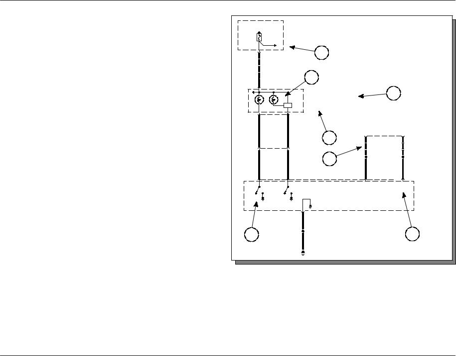
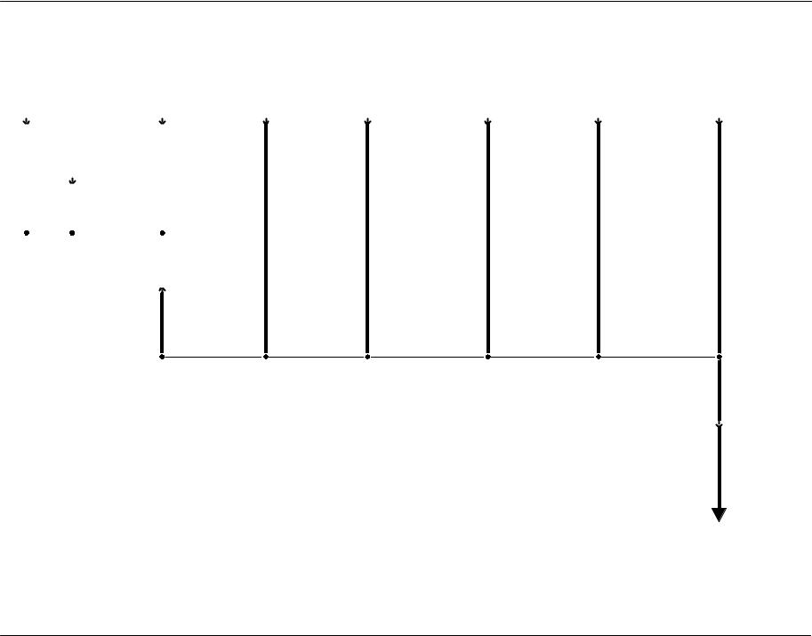
Current Flow (1)
Each cell normally starts with the component that powers the circuit, such as a fuse or the ignition switch. Current flow is shown from the power source at the top of the page to ground at the bottom of the page. In order to concentrate on the essential parts, power supply and ground connections are sometimes simplified by a dashed line in the schematics. A full representation of the power supply of a fuse or the power distribution from a fuse to various components is given in cell 13 “Power Distribution”. Full representation of the ground connections are shown in cell 10 “Grounds”.
Switch Positions (2)
Within the schematic, all switches, sensors and relays are shown “at rest” (as if the Ignition Switch were OFF).
Splices (3)
A dashed line indicates that the splice is not shown completely. A reference is given to the page where the splice appears in full. It is also listed in the Index.
|
Hot in run |
|
Central Junc- |
|
|
|
|
|
|
|
|
|
tion Box (CJB) |
|
|
|
|
|
|
||
|
|
|
|
|
|
|
|
|
||
|
F2.6 |
|
(14A067) |
|
|
|
|
|
|
|
|
|
13−4 |
|
|
|
|
|
|
|
|
|
5A |
|
|
|
|
|
|
|
|
|
31 |
C270a |
|
|
|
1 |
|
|
|
|
|
1405 |
LB/BK |
|
|
|
|
|
|
|
|
|
|
See page |
|
6 |
|
|
|
|
|
|
|
|
13−8 |
|
|
|
|
|
|
|
|
|
11 |
C220a |
|
|
|
|
|
|
|
|
|
|
|
|
|
Instrument cluster (10849) |
|
5 |
|
|
||
|
|
|
|
1) |
Traction control |
|
|
|
|
|
|
|
12 |
|
12) |
ABS |
|
|
|
|
|
|
1 |
|
|
62−3 |
|
|
|
|
|
|
4 |
|
16 |
C220a |
|
|
|
Data Link Con- |
|
|
|
|
|
|
|
|
|
|
|
|
||
939 |
VT |
603 |
DG |
|
|
|
nector (DLC) |
|
|
|
|
|
|
(14489) |
|
|
|
||||
|
|
|
|
|
|
|
|
|
|
|
|
|
|
|
|
4 |
2 |
|
10 |
C251 |
|
15 |
|
27 |
C1019 |
|
|
|
See page |
|
See page |
|
|
|
|
|
|
|
|
14−3 |
|
14−3 |
|
939 |
VT |
603 |
DG |
|
3 |
|
S157 |
|
S156 |
|
|
|
|
|
|
|
|||||
|
|
|
|
|
|
914 |
TN/OG |
915 |
PK/LB |
|
7 |
|
15 |
|
|
|
3 |
|
11 |
C135 |
|
|
|
|
|
|
|
SCP + |
SCP − |
ABS control |
||
|
|
|
|
|
|
module (2C219) |
||||
|
|
|
|
|
|
|
|
|
|
151−5 |
|
|
|
8 |
|
|
|
|
|
|
|
|
|
|
530 |
LG/YE |
|
|
|
|
|
|
2 |
|
|
|
S200 |
|
|
|
7 |
|
|
|
|
530 |
LG/YE |
|
|
|
|
|||
|
|
|
|
|
|
|
|
|||
|
|
|
|
G104 |
|
|
|
|
|
|

Introduction 3-2
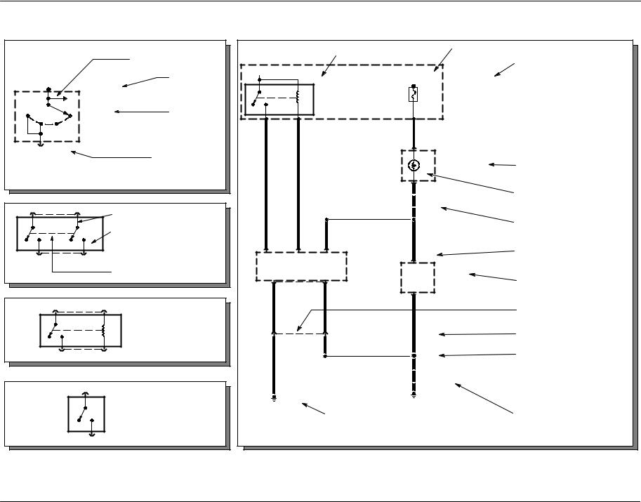
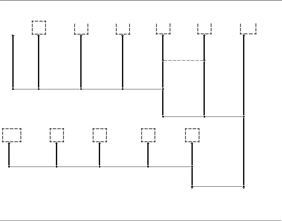
Component Referencing (4)
Each component on a schematic has a reference to the component location view or the page where it is shown completely. It is located to the right of each component.
Component Names, Notes and Base Part Numbers (5)
Component names are placed on the right hand side of each component. Any notes that describe switch positions or operating conditions follow the name. Descriptions of the internals of the component are also included here. The page where the component appears in full is listed in the Index. The base part number for a component is listed in parentheses next to or under a component. These part numbers will appear any place the component name appears in the publication.
Internal Name and Function Identification Numbers (6)
Some components on each page have internal symbols with an identification number located to the right. You can identify the internal symbol or function by finding the corresponding number under the component name.
Circuit Function Identifiers (7)
Some components without internal schematics use symbols or text to describe the function of a circuit in a system.
3-3 Introduction
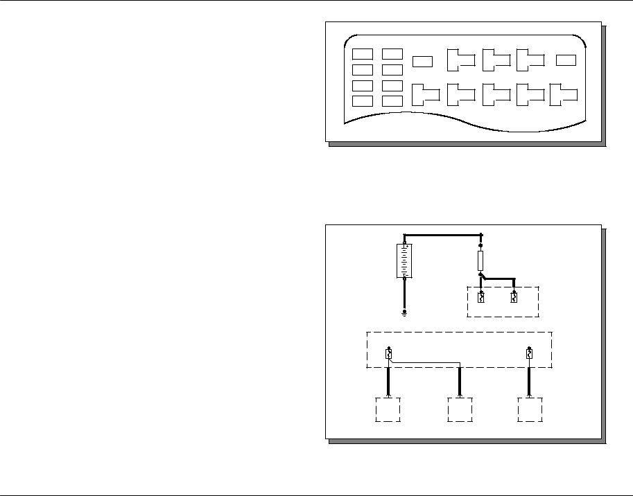
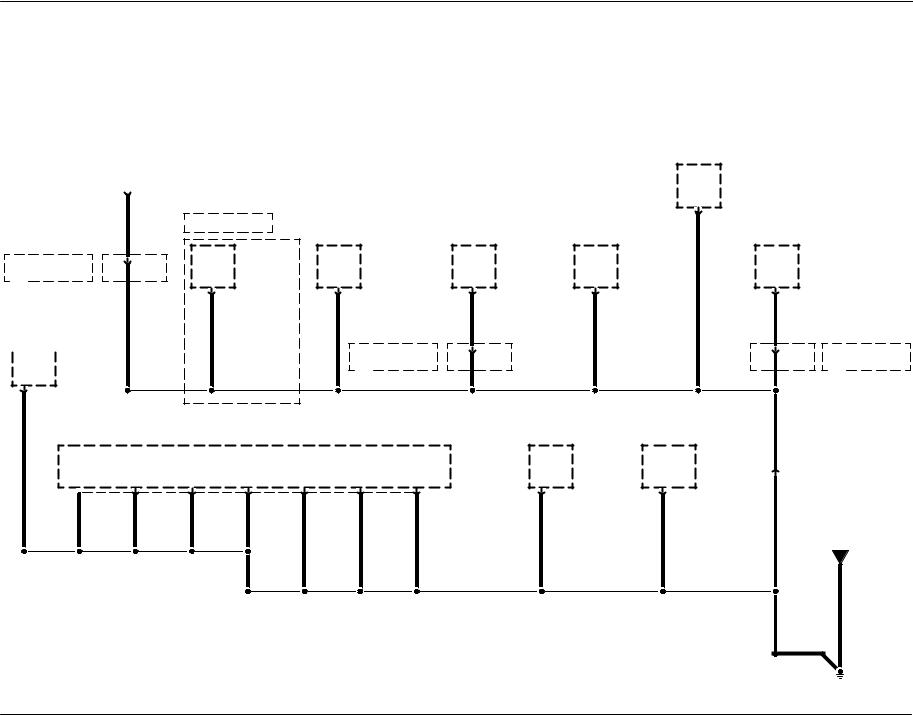
Fuse and Relay Information
Cell 11 “Fuse and Relay Information” contains a view of the fuse-/relay box in which all fuses and relays are identified.
Fuse and Relay Numbering and Naming
Fuse and relay numbering and naming follow the indication of the fuse panel cover. In addition, a prefix precedes the fuse number to facilitate finding the fuse in the Component Location Charts, e.g. “F1.” precedes Power Distribution Center fuses, and “F2.” precedes Central Junction Box fuses.
F1.12 |
F1.1 |
F1.23 |
|
F1.24 |
|
F1.13 |
F1.2 |
|
F1.14 |
F1.3 |
|
F1.15 |
F1.4 |
|
Power Distribution
Cell 13 “Power Distribution” shows the current feed circuit. The current path is shown from the battery to the ignition switch and to all fuses. It also shows the circuits protected by each fuse. The circuit is traced from the fuse to the component. All details (wires, splices, connectors) between the fuse and the first component are shown.
|
Battery |
|
S130 |
|
|
|
|
|
|
Fusible Link A |
|
|
|||
|
|
|
|
|
|||
|
|
|
1) |
12 gauge |
|
|
|
|
|
|
2) |
gray |
|
|
|
|
|
|
S131 |
|
|
|
|
|
57 BK |
|
|
|
|
Power |
|
|
|
F1.20 |
F1.21 Distributi |
||||
|
|
|
10A |
20A |
on Center |
||
|
G1002 |
|
|
|
|
(PDC) |
|
|
|
|
|
|
|
|
|
Hot at all times |
|
|
|
Hot at all times |
Power |
||
|
|
|
Distributio |
||||
|
|
|
|
|
|
|
|
|
F1.1 |
|
|
|
|
F1.2 |
n Center |
|
30A |
|
|
|
|
20A |
(PDC) |
|
|
|
|
|
|
||
932 |
RD |
932 |
RD |
|
196 |
DB/OG |
|
1 |
C1041 |
1 |
C1021 |
|
7 |
C220 |
|
|
Headlamp, |
|
Headlamp, |
|
Instrument |
||
|
right |
|
left |
|
|
cluster |
|
|
85−1 |
|
85−1 |
|
|
60−1 |
|
Introduction 3-4
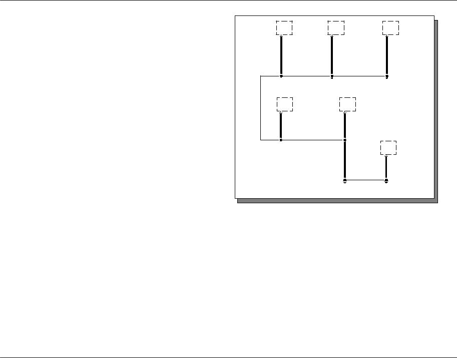
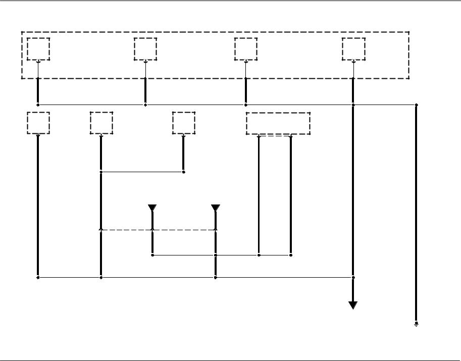
Ground Distribution
Cell 10 “Grounds” contains the schematics that show the complete details for each ground connection or main ground splice. This is useful in diagnosing a problem affecting several components at once (poor ground connection or ground splice). All details (wires, splices, connectors) between the ground point and the components are shown. These ground connection details are shown here in order to keep the individual cell schematics as uncluttered as possible.
|
Headlamp, |
|
Fog lamp, |
|
right (13008) |
|
right front |
|
85−2 |
|
(15200) |
2 |
C1041 |
1 |
C162 86−1 |
57 |
BK |
57 |
BK |
|
Fog lamp, |
|
front left |
|
(15200) |
1 |
C152 86−1 |
57 |
BK |
Side lamp, left front (13411)
92−1
2 |
C1127 |
57 |
BK |
|
Headlamp, |
|
|
|
left (13008) |
|
|
|
85−2 |
|
|
2 |
C1021 |
|
|
57 |
BK |
|
|
|
S102 |
|
Side lamp, right |
|
|
|
|
|
|
|
front (13411) |
|
|
|
92−1 |
|
|
2 |
C1126 |
57 |
BK |
57 |
BK |
|
|
|
G100 |
|
|
|
151−3 |
3-5 Introduction
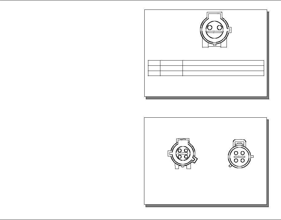
Component and Connector Information
Cell 152 “Component Location Charts” helps the user find where the various items depicted on the schematic can physically be found on the vehicle. A brief written description of the location is given, along with a reference to the component location views.
Cell 151 “Component Location Views” show the components and their connecting wires as they can be found on the vehicle.
Cell 150 “Connector Views” show the views of the pins and/or cavities of all connectors. The pin and cavity sides are shown separately as if the connector were disconnected. The color of the connector housing is indicated next to the connector number when available. The harness causal number is located above the component name and below the connector number or above the connector face itself. Wiring harness designations are listed in cell 152 “Component Location Charts”. Circuit function charts are located below each connector.
C150 (BK)
12A581
Wheel speed sen- |
|
|
|
sor, left front |
2 |
1 |
|
(2C205) |
|
|
|
|
|
FEMALE |
|
Pin |
Circuit |
|
Circuit Function |
1 |
522 (TN/BK) |
Wheel speed sensor, left front (2C205) − |
|
2 |
521 (TN/OG) |
Wheel speed sensor, left front (2C205) + |
|
C1033 (BK)
|
12B637 |
|
|
14B102 |
|
|
4 |
2 |
|
|
|
|
|
|
2 |
|
4 |
|
3 |
1 |
1 |
|
3 |
|
|
|
|
||
|
|
FEMALE |
|
|
MALE |
(1) |
− |
|
|
(3) |
359 (GY/RD) |
(2) |
1102 (YE/LG) |
|
(4) |
− |
|
Introduction 3-6
WARNINGS
!
D Always wear safety glasses for eye protection.
DUse safety stands whenever a procedure requires being under a vehicle.
DBe sure that the Ignition Switch is always in the OFF position, unless otherwise required by the procedure.
DSet the parking brake when working on any vehicle. An automatic transmission should be in PARK. A manual transmission should be in NEUTRAL.
DOperate the engine only in a well-ventilated area to avoid danger of carbon monoxide.
DKeep away from moving parts, especially the fan and belts, when the engine is running.
DTo prevent serious burns, avoid contact with hot metal parts such as the radiator, exhaust manifold, tail pipe, catalytic converter and muffler.
DDo not allow flame or sparks near the battery. Gases are always present in and around the battery cell. An explosion could occur.
D Do not smoke when working on a vehicle.
DTo avoid injury, always remove rings, watches, loose hanging jewelry and avoid wearing loose clothing.
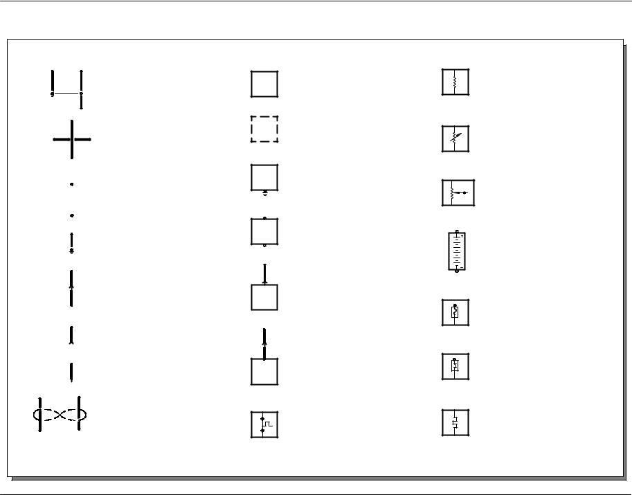
4 -1 Symbols
Distributed splice
Crossed wiring without connection
Splice
Removable connection
Ground
Connector
Female connector
Male connector
Twisted pair
Entire component
Part of a component
Component case directly attached to metal part of vehicle (ground)
Component with screw terminals
Connector attached to component
Connector attached to component lead (pigtail)
Positive Temperature Coefficient (PTC)
Resistor
Potentiometer (pressure or temperature)
Potentiometer (outside influence)
Battery
Fuse
Circuit breaker
Heating element, Conductor loop
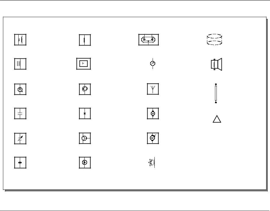
Symbols 4 -2
Ignition coil assembly
Solenoid controlled valve or clutch solenoid
Light emitting diode (LED)
Capacitor
Variable capacitor
Piezoelectric sensor
Coil |
Bifilament lamp |
Shield |
Hall sensor |
|
|
|
Gauges |
Horn or speaker |
|
|
|
|||
|
|
|
|||
|
|
|
|
|
|
Air bag sliding contact |
Antenna |
Fusible link |
(14A664) |
|
|
Diode, current flows in |
Permanent magnet, |
direction of arrow |
one−speed−motor |
Warning
!
Transistor |
Permanent magnet, |
|
two−speed−motor |
Lamp |
|
Rotational sensor |
|
||
|
|
|
4-3 Symbols
Wire colors
BK |
Black |
BN |
Brown |
BU |
Blue |
DB |
Dark blue |
DG |
Dark green |
GN |
Green |
GY |
Gray |
LB |
Light blue |
LG |
Light green |
NA |
Natural |
OG |
Orange |
PK |
Pink |
RD |
Red |
SR |
Silver |
TN |
Tan |
VT |
Violet |
WH |
White |
YE |
Yellow |
|
|
VREF |
|
PWR |
|
|
|
|
|
|
|
|
|
|
|
|
|
|
|
|
|
|
VBATT |
VPWR |
|
SCP + |
SCP − |
ISO |
Reference volt- |
|
Switched power |
Battery voltage |
Switched or |
Standard Cor- |
Standard Corpo- |
Data bus ISO |
|
age |
|
|
|
module voltage |
porate Proto- |
rate Protocol |
9141 (K−line) |
|
|
|
|
|
|
|
col (SCP) |
(SCP) data − |
|
|
|
|
|
|
|
data + |
|
|
|
|
|
− |
SIG |
|
|
|
|
|
|
|
|
RTN |
|
|
|
|
|
|
+ |
|
|
− |
|
|
|
signal |
signal |
signal |
Signal return |
Signal return |
Switched |
Ground |
||
|
|
|
|
|
|
|
ground |
|
Joint connector |
1 |
C120 |
|
|
|
|
|
|
359 |
GY/RD |
jumper |
|
|
|
|
|
3 |
C200 |
|
|
4 |
C200 |
|
|
359 |
GY/RD |
|
2 C120
Symbols 4 -4
Hot in Start or Run
F1.18
15A
910 
 GY/BK
GY/BK
See page 13-1
53 
 C240
C240
Power Distribution Center (PDC) (14A003)
Other circuits which share fuse 18, but are not shown, can be referenced in Power Distribution
Circuit number |
|
|
|
329 |
PK |
Wire insulation is one |
|
color |
|||
|
|
||
4 |
C100 |
|
|
|
|
Connector reference |
|
57 |
BK |
number for component |
|
location chart |
|||
|
|
||
|
G100 |
Ground numbered for |
|
Pin number |
|
reference to component |
|
|
|
location chart |
A choice bracket shows wiring differences between models, countries or options
Windshield wiper motor (17508)
1  C125
C125
57  BK
BK
See page 10-1
G100
Other circuits which are also grounded at G100, but are not shown, can be referenced in Grounds
Wire insulation is one color with another color stripe (green with white)
329 GN/WH
29−1 Transmission Controls
Reference to another cell where circuit is shown completely
See page 46−1
A
A
See page 46−2
Cut wires referenced between pages. Arrows show current flow from power to ground.
359 |
|
|
GY/RD |
|
|
|
|
|
|
|
|
|
|
|
|
|
|
|||||||||
|
|
329 |
|
|
PK |
|
|
|
|
|
||||||||||||||||
3 |
|
4 |
|
|
|
|
C103 |
|
|
|
|
|
||||||||||||||
|
|
|
|
|
|
|
|
|
|
|
|
|
|
|
|
|
|
|
|
|
|
|
|
|
|
|
359 |
|
|
GY/RD |
|
|
|
|
|
|
|
|
|
|
|
|
|
|
|||||||||
|
|
|
|
|
|
|
|
|
|
|
|
|
|
|
|
|||||||||||
|
|
|
|
|
|
|
|
|
|
|
|
|
|
|
|
|
|
|
|
|
|
|
|
|
|
|
|
|
|
|
|
|
|
|
|
|
|
|
|
|
|
|
|
|
|
|
|
|
|
|
|
|
|
|
|
|
|
|
|
|
|
|
|
|
|
|
|
|
|
|
|
|
|
|
|
|
|
|
|
|
|
|
|
|
|
|
|
|
|
|
|
|
|
|
|
|
|
|
|
|
|
|
|
|
|
|
|
|
|
|
|
|
|
|
|
|
|
|
|
|
|
|
|
|
|
|
|
|
|
|
|
|
|
|
|
|
|
|
|
|
|
|
|
|
|
|
|
|
|
|
|
|
|
|
|
|
|
|
|
|
|
|
|
|
|
|
|
|
|
|
|
|
|
|
|
|
|
|
|
|
|
|
|
|
|
|
|
|
|
|
|
|
|
|
|
|
|
|
|
|
|
|
|
|
|
|
|
|
|
|
|
|
|
|
|
|
|
|
|
|
|
|
|
|
|
|
|
|
|
|
|
|
|
|
|
|
|
|
|
|
|
|
|
|
|
|
|
|
|
|
|
|
|
|
|
|
|
|
|
|
|
|
|
|
|
|
|
|
|
|
|
|
|
|
|
|
|
|
|
|
|
|
|
|
|
|
|
|
|
|
|
|
|
|
|
|
|
|
|
|
|
|
|
|
|
|
|
|
|
|
|
|
|
|
|
|
|
|
|
|
|
|
|
|
|
|
|
|
|
|
|
|
|
|
|
|
|
|
|
|
|
|
|
|
|
|
|
|
|
|
|
|
|
|
|
|
|
|
|
|
|
|
|
|
|
|
|
|
|
|
|
|
|
|
|
|
|
|
|
|
|
|
|
|
|
|
|
|
|
|
|
|
|
|
|
|
|
|
|
|
|
|
|
|
|
|
|
|
|
|
|
|
|
|
|
|
|
|
|
|
|
|
|
|
|
|
|
|
|
|
|
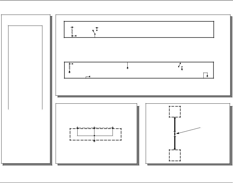
Two connections (pins) in the same connector
Dashed line indicates terminals for the same connector
Shorting bar
Busbar
F1.3 |
F1.14 |
10A |
10A |
4 -5 Symbols
|
|
|
|
Indicates incomplete |
|
|
|
|
internal bussing |
|
|
|
|
Name of com- |
|
|
|
|
ponent |
|
|
Ignition switch |
|
|
|
|
(11572) |
|
|
|
|
0) |
Off |
Details about |
3 |
|
0 1) |
Acc |
component or |
2 |
1 |
2) |
Run |
operation |
|
|
|
||
3 |
C300 |
3) |
Start |
|
|
|
|
||
Component connector number
Switches that move together
|
|
|
|
Reference number indicates |
2 |
1 |
2 |
1 |
switch position |
|
Dashed line shows a mechanical connection between switches
Normally open contact When coil is energized, switch is activated
One pole, two position switch
2 1
Relays shown without a connector number are |
|
|
Fuse condition |
||||
non−serviceable components |
|
|
|
|
|
||
Hot in Start or Run |
|
|
Hot at all times |
Central Junction |
|||
|
|
Box (CJB) |
|||||
|
|
|
|
|
|
|
|
|
|
Fuel pump relay |
|
F2.23 |
|
||
|
|
|
|
|
|
|
|
|
|
|
|
|
|
3A |
|
|
|
|
|
|
720 |
RD/YE |
|
238 DG/YE |
|
|
|
5 |
C220 |
|
|
|
|
|
|
|
Instrument cluster |
||
|
|
|
|
|
|
|
|
|
|
|
|
|
|
6 |
6) Illumination |
|
238 |
LB/OG |
|
|
|
|
|
|
|
|
4 |
C220 |
|
||
|
|
|
|
|
|
||
|
|
|
|
|
|
See page |
|
|
|
|
|
|
|
13−1 |
|
|
|
|
|
|
|
S100 |
|
|
|
19 |
LB/RD |
|
19 |
LB/RD |
|
16 |
18 |
17 |
C175 |
|
|
|
|
|
|
|
|
Engine |
1 |
C135 |
|
|
|
|
|
Control |
|
|
ABS control |
|
|
|
|
Module (ECM) |
|
module |
|
33 |
|
19 |
C175 |
(12A650) |
|
|
(2C219) |
57 |
BK |
57 |
BK |
|
2 |
C135 |
|
4 |
|
2 |
C201 |
|
57 |
BK |
|
|
|
|
|
|
|
||
|
|
|
|
|
|
S101 |
|
|
|
|
|
|
|
See page |
|
|
|
|
|
|
|
10−1 |
|
|
G102 |
|
|
|
|
G101 |
|
Ground numbered for reference to component location chart
Name of component
Details about component or operation
Reference number for internal component name
Reference to page where circuit is shown complete
Component connector number
Base service part number
Dashed line indicates terminals for the same connector
Wire insulation is one color
Splice numbered for reference in component location chart
Other circuits which are also grounded at G100, but are not shown, can be found using the reference

Symbols 4 -6
The first digit of every connector, ground, and splice number used in this publication references its location within the vehicle.
The chart below describes the different sections of the vehicle, and lists the number associated with each.
Number |
Location |
|
100−199 |
front fascia, hood, front fenders, front axle, En- |
|
1000−1999 |
gine compartment, Powertrain (including: axle/ |
|
|
differential/transmission/exhaust system) |
|
|
|
|
200−299 |
Instrument Panel and Center Stack Console, |
|
2000−2999 |
Steering wheel assembly, front kick panels, |
|
|
cowl panel (body side) |
|
|
|
|
300−399 |
From instrument panel to rear seat, A, B, C |
|
3000−3999 |
pillars below door trim panel, center console |
|
400−499 |
behind rear seats, to rear bumper; Truck bed, |
|
4000−4999 |
Tailgate, Liftgate, Rear fenders |
|
|
|
|
500−599 |
left front door |
|
|
|
|
600−699 |
right front door |
|
|
|
|
700−799 |
left rear door |
|
|
|
|
800−899 |
right rear door |
|
|
|
|
900−999 |
A, B, C pillars Above door trim panel and |
|
|
headliner |
|
|
|
|

5-1 Connector Repair Procedures
Troubleshooting wiring harness and connector hidden concerns
The following illustrations are known examples of wiring harness, splices and connectors that will create intermittent electrical concerns. The concerns are hidden and can only be discovered by a physical evaluation as shown in each illustration.
NOTE: Several components, such as the ECM, utilize gold plated terminals in their connections to the wiring harness. If those terminals need to be replaced, they must be replaced with a gold plated terminal.
Terminal not properly seated
1 |
= |
Locked terminal |
2 |
= |
Male half |
3 |
= |
Female half |
4 |
= |
Seal |
5 |
= |
Intermittent contact |
6 |
= |
Unlocked terminal (Hidden by wire seal) |
7 |
= |
Seal |
Check for unlocked terminals by pulling each wire at the end of the connector.

Connector Repair Procedures |
5-2 |
|
|
Defective insulation stripping
1= Proper crimp
2= Insulation not removed
3= Wire strands missing
4= Intermittent signals through pierced insulation
Partially mated connectors
1 = Seal
2= Displaced tab
3= Female half
4 = Seal
5= Intermittent contact
6= Male half
7= Intermittent contact
Lock may be displaced into an unlocked position; pull on the connector to verify the lock.

5-3 Connector Repair Procedures
Deformed (enlarged) female terminals
1 |
= |
Enlarged |
2 |
= |
Normal |
Any probe entering the terminal may enlarge the contact spring opening creating an intermittent signal. Insert the correct mating terminal (Location A) from the service kit and feel for a loose fit.
Electrical short inside the harness
1= Solder coated wire to ground
2= Harness protective tape
3= Intermittent short
Solder coated wire pierced through the insulation of another circuit
4 = Grounding foil

Connector Repair Procedures |
5-4 |
|
|
Electrical short within the harness
Splice tape removed
1 = Intermittent short
Splice covered
2= Wire strand
3= Splice tape
4= Harness tape
Broken wire strands in harness
1= Wiring harness tape
2= Wiring strand
3= Broken strands intermittent signal
4= Circuit insulation
Remove the tape and flex/feel each circuit for a reduction in diameter at break.

5-5 Connector Repair Procedures
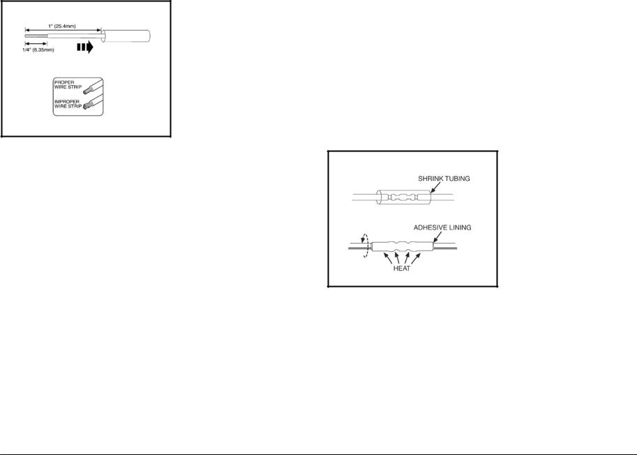
Recommended splicing method −Solder (For 16 AWG and Smaller Diameter Wire Only)
1.Disconnect battery ground cable.
2.Strip wires to appropriate length.
3.Install heat shrink tubing.
4.Twist wires together.
5.Solder wires together.
NOTE: Use rosin core mildly-activated (RMA) solder. Do not use acid core solder.
6.Bend wire 1 back in a straight line.
NOTE: Wait for solder to cool before moving wires.
7.Evenly position heat shrink tubing over wire repair.
NOTE: Overlap tubing on both wires.
8.Use shielded heat gun to heat the repaired area until adhesive flows out of both ends of heat shrink tubing.
9.Reconnect battery ground cable.
Connector Repair Procedures |
5-6 |
|
|
Recommended splicing method −Crimp (For 10−22 AWG Diameter Wire to Like Wire Diameter)
1.Disconnect battery ground cable.
2.Remove proper amount of insulation from each wire end, taking care not to nick or cut wire strands.
3.Install heat shrink tubing.
4.Select appropriate wire splice for the wires to be spliced.
5.Install the wire ends into the splice, making sure the ends of the wires
are fully inserted.
6.Using the proper crimping tool for the splice, hand crimp the wires and splice.
7.Gently tug on the wires to be sure they are secure.
8.Electrically check the circuit for continuity through the splice.
9.Evenly position supplied heat shrink tubing over wire repair.
10.Use shielded heat gun to heat the repaired area until adhesive flows out of both ends of the heat shrink tubing.
11.Reconnect battery ground cable.

9-1 Wiring Harness Overview
9 |
5 |
8 |
1
4
2
3
7
6
Connector
Grommet
Wiring Harness Overview |
9 -2 |
|
|
Item |
Part Number |
Description |
|
|
|
1 |
14335 |
Wiring harness − Interior illumination |
2 |
9D930 |
Wiring harness − Fuel charge |
3 |
12B637 |
Wiring harness − Engine control sensor |
4 |
12A581 |
Wiring harness − Main |
5 |
14401 |
Wiring harness − Instrument panel |
6 |
14405 |
Wiring harness − Rear Chassis |
7 |
14A005 |
Wiring harness − Floor |
8 |
14631 |
Wiring harness − driver door |
9 |
14630 |
Wiring harness − passenger door |
|
|
|
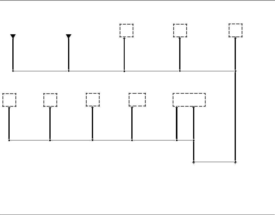
10 -1 Grounds
G100
See page |
See page |
|
Windshield |
|
Door lock timer |
|
Indicator flasher |
|
washer pump |
|
110−1 |
|
relay (13350) |
||
10−2 |
10−3 |
|
|
|
|||
|
motor (17618) |
|
|
|
90−1 |
||
A |
B |
|
|
|
|
||
|
81−1 |
|
|
|
|
||
|
|
|
12 |
C2333 |
5 |
C2047 |
|
|
|
A |
C137 |
||||
57 BK |
57 BK |
57 |
BK |
57 |
BK |
57 |
BK |
|
|
|
|
|
|
|
S203 |
|
Headlamp, right |
|
Pusher fan relay |
|
Cigar lighter, |
|
|
Function selec- |
|
|
|
|
Multifunction |
|
(13008) |
|
54−4 |
|
front (15055) |
|
|
tor switch as- |
|
|
|
|
switch |
|
85−2 |
|
|
|
44−1 |
|
|
sembly |
|
|
|
|
81−1, 85−1, 92−1 |
|
|
|
|
C |
C2031 |
1 |
C294a |
(19B888) |
16 |
C202a |
5 |
C202b |
|
B |
C1041 |
2 |
C2346 |
54−2 |
|
||||||||
57 |
BK |
57 |
BK |
57 |
BK |
57 |
BK |
|
57 |
BK |
57 |
BK |
57 BK |
|
|
|
|
|
|
||||||||
|
|
|
|
|
|
|
|
|
|
|
|
S202 |
|
|
|
|
|
|
|
|
|
|
|
|
57 |
BK |
|
G100
151−12
Grounds 10 -2
|
|
|
|
|
|
|
|
|
|
|
|
|
|
|
|
|
|
|
|
|
|
|
|
|
|
|
|
|
|
|
|
|
|
|
|
|
|
|
|
|
|
|
|
Auxiliary relay |
|
|
|
|
|
|
|
|
|
|
|
|
|
|
|
|
|
|
|
|
|
|
|
|
|
|
|
|
|
|
|
|
|
Power window |
|
||||||||||
|
|
|
|
|
|
|
|
|
Ashtray illumi- |
|
|
|
|
|
|
|
|
|
|
|
|
|
|
|
|
|
|
|
|
|
|
|
box 1 |
|||||||||||
|
|
|
|
|
|
|
|
|
|
|
|
|
|
|
|
|
Function selec- |
|
|
|
|
|
|
|
|
|
|
|
|
|
|
|
||||||||||||
|
|
|
|
|
|
|
|
|
|
|
|
|
|
|
|
|
|
|
|
|||||||||||||||||||||||||
|
|
|
|
|
|
|
|
|
nation lamp |
|
|
|
|
|
|
|
|
tor switch as- |
|
|
|
|
|
|
|
|
|
|
|
|
|
|
relay |
|
11−3, 151−9 |
|||||||||
|
|
|
|
|
|
|
|
|
|
|
|
|
|
|
|
|
|
|
|
|
|
|
|
|
|
|
|
|
|
|
|
|||||||||||||
|
|
|
|
|
|
|
|
|
|
|
|
|
|
|
|
|
|
|
|
|
|
|
|
|
|
|
|
|
|
|
100−1 |
|
|
|||||||||||
|
|
|
|
|
|
|
|
|
71−1 |
|
|
|
|
|
|
|
|
sembly |
|
|
|
|
|
|
|
|
|
|
|
|
|
|
|
|
||||||||||
|
|
|
|
|
|
|
|
|
|
|
|
|
|
|
|
|
|
(19B888) |
|
|
|
|
|
|
|
|
|
|
|
|
|
|
|
|
|
|
|
|
|
|
|
|
|
|
|
B |
|
C2246 |
2 |
|
C294c |
54−1 |
|
|
86 |
|
|
|
C2218 |
|
|
||||||||||||||||||||||||||||
|
|
|
|
|
|
|
|
|
|
|
|
|
|
|
|
|
|
|
|
|
|
|
|
|
|
|
|
|
|
|
|
|
|
|
|
|
|
|
|
|
|
|
|
|
|
|
|
|
|
|
|
|
|
|
|
|
|
|
|
|
|
|
|
|
|
|
|
|
|
|
|
|
|
||||||||||||||||
|
|
|
|
|
|
|
|
|
|
|
|
|
|
|
|
|
|
|
|
|
|
|
|
|
|
|
|
|
|
|
|
|
|
|
|
|
|
|
|
|
|
|
|
|
57 |
|
|
BK |
57 |
|
BK |
|
|
|
57 |
|
|
|
BK |
|
|
||||||||||||||||||||||||||||
|
|
|
|
|
|
|
|
|
|
|
|
|
|
|
|
|
|
|
|
|
|
|
|
|
|
|
|
|
|
|
|
|
|
|
|
|
|
|
|
|
|
|
|
|
|
Ashtray illumi- |
|
Hazard flasher |
|
|
Speed control |
|
Speed control |
|
nation lamp |
|
switch |
|
|
Set/Resume |
|
On/Off switch |
|
71−1 |
|
90−1 |
|
|
switch |
|
31−2 |
B |
C2014 |
9 |
C2039 |
G |
C2177 |
31−2 |
2 |
C2178 |
|
||||||||
57 |
BK |
57 |
BK |
57 |
BK |
|
57 |
BK |
|
|
|
|
|
|
|
|
S204 |
57 BK
A
See page 10−1
10 -3 Grounds
|
|
|
|
|
|
|
|
|
|
|
Parking brake |
|
|
|
|
|
|
|
|
|
|
|
Floor shifter |
|
|
|
|
|
|
|
|
|
|
|
Roof marker |
|
|
|
|
|
|
|
|
|
|
|
|
|
Roof marker |
|
|
|
|
|
|
|
|
|
|
|
Roof marker |
|
|
|
|
|
|
|
|
|
|
|
|
|
|
|
Roof marker |
|
|
|
|
|
|
|
|
|
|
|
Roof marker |
||||||||||
|
|
|
|
|
|
|
|
|
|
|
|
|
|
|
|
|
|
|
|
|
|
|
|
|
|
|
|
|
|
|
|
|
|
|
|
|
|
|
|
|
|
|
|
|
|
|
|
|
|
|
|
|
|
|
|
|
|
|
|
|
|
|
|
||||||||||||||||||||||||||||||||||||
|
|
|
|
|
|
|
|
|
|
|
switch (15A851) |
|
|
|
|
|
|
|
|
|
|
|
29−4 |
|
|
|
|
|
|
|
|
|
|
|
lamp, left |
|
|
|
|
|
|
|
|
|
|
|
|
|
lamp, left cen- |
|
|
|
|
|
|
|
|
|
|
|
lamp, center |
|
|
|
|
|
|
|
|
|
|
|
|
|
|
|
lamp, right cen- |
|
|
|
|
|
|
|
|
|
|
|
lamp, right |
||||||||||
|
|
|
|
|
|
|
|
|
|
|
|
|
|
|
|
|
|
|
|
|
|
|
|
|
|
|
|
|
|
|
|
|
|
|
|
|
|
|
|
|
|
|
|
||||||||||||||||||||||||||||||||||||||||||||||||||||||||
|
|
|
|
|
|
|
|
|
|
|
60−2 |
|
|
|
|
|
|
|
|
|
|
|
|
|
|
|
|
|
|
|
|
|
|
|
|
|
|
|
|
|
|
92−2 |
|
|
|
|
|
|
|
|
|
|
|
|
|
ter |
|
|
|
|
|
|
|
|
|
|
|
92−2 |
|
|
|
|
|
|
|
|
|
|
|
|
|
|
|
ter |
|
|
|
|
|
|
|
|
|
|
|
92−2 |
|||
|
|
|
|
|
|
|
|
|
|
|
|
|
|
|
|
|
|
|
|
|
|
|
|
|
|
|
|
|
|
|
|
|
|
|
|
|
|
|
|
|
|
|
|
|
|
|
|
|
|
|
|
|
|
|
|
|
|
||||||||||||||||||||||||||||||||||||||||||
|
|
|
|
|
|
|
|
|
|
|
|
|
|
|
|
|
|
|
|
|
|
|
|
|
|
|
|
|
|
|
|
|
|
|
|
|
|
|
|
|
|
|
|
|
|
|
|
|
|
|
|
|
|
|
|
|
|
|
92−2 |
|
|
|
|
|
|
|
|
|
|
|
|
|
|
|
|
|
|
|
|
|
|
|
|
|
|
|
92−2 |
|
|
|
|
|
|
|
|
|
|
|
|
|
A |
|
|
C306 |
|
|
|
|
|
|
Safety belt |
|
F |
|
|
C3245 |
3 |
|
|
|
|
|
C970 |
3 |
|
|
C971 |
3 |
|
|
|
C972 |
3 |
|
|
|
|
C973 |
3 |
|
|
|
C974 |
||||||||||||||||||||||||||||||||||||||||||||||||||||||||
|
|
|
|
|
|
|
|
|
|
|
|
|
|
|
|
|
|
|
|
|
|
|
|
|
|
|
|
|
|
|
|
|
|
|
|
|
|
|
|
|
|
|
|
|
|
|
|
|
|
|
|
|
|
|
|
|
|
|
|
|
|
|
|
|
|
|
|
|
|
|
|
|
|
|
|
|
|
|
|
|
|
|
|
|
|
|
|
|
|
|
|
|
|
|
|
|
|
|
|
|
|
|
|
|
|
|
|
|
|
|
|
|
|
|
|
|
|
|
|
|
|
|
|
|
|
|
|
|
|
|
|
|
|
|
|
|
|
|
|
|
|
|
|
|
|
|
|
|
|
|
|
|
|
|
|
|
|
|
|
|
|
|
|
|
|
|
|
|
|
|
|
|
|
|
|
|
|
|
|
|
|
|
|
|
|
|
|
|
|
|
|
|
|
|
|
|
|
|
|
|
|
|
|
|
|
|
|
|
|
|
|
|
|
|
|
|
|
|
|
|
buckle switch |
|
|
|
|
|
|
|
|
|
|
|
|
|
|
|
|
|
|
|
|
|
|
|
|
|
|
|
|
|
|
|
|
|
|
|
|
|
|
|
|
|
|
|
|
|
|
|
|
|
|
|
|
|
|
|
|
|
|
|
|
|
|
|
|
|
|
|
|
|
|
|
|
|
|
||||
|
|
|
|
|
|
|
|
|
|
|
|
|
|
|
|
|
|
|
|
|
|
|
|
|
|
|
|
|
|
|
|
|
|
|
|
|
|
|
|
|
|
|
|
|
|
|
|
|
|
|
|
|
|
|
|
|
|
|
|
|
|
|
|
|
|
|
|
|
|
|
|
|
|
|
|
|
|
|
|
|
|
|
|
|
|
|
|
|
|
|
|
|
|
|
|||||
57 |
|
|
|
BK |
|
|
|
|
|
|
|
|
|
(10B924) |
|
|
|
|
|
|
|
|
|
|
|
|
57 |
|
|
|
|
|
BK |
57 |
|
|
BK |
57 |
|
|
|
BK |
57 |
|
|
|
|
BK |
57 |
|
|
|
BK |
||||||||||||||||||||||||||||||||||||||||||||||
|
|
|
|
|
|
|
|
|
|
|
|
|
|
|
|
|
|
|
|
|
|
|
|
|
|
|
|
|
|
|
|
|
|
|
|
|
|
|
|
|
|||||||||||||||||||||||||||||||||||||||||||||||||||||||||||
|
|
|
|
|
|
|
|
|
|
|
|
60−2 |
|
|
|
|
|
|
|
|
|
|
|
|
|
|
|
|
|
|
|
|
|
|
|
|
|
|
|
|
|
||||||||||||||||||||||||||||||||||||||||||||||||||||||||||
|
|
|
|
|
|
|
|
|
|
|
|
|
|
|
|
|
|
|
|
|
|
|
|
|
|
|
|
|
|
|
|
|
|
|
|
|
|
|
|
|
|
|
|
|
|
|
|
|
|
|
|
|
|
|
|
|
|
|
|
|
|
|
|
|
|
|
|
|
|
|
|
|
|
|
|
|
|
|
|
|
|
|
|
|
|
|
|
|
|
|
|
|
|
|
|
|
|
|
|
|
|
|
|
|
3 |
|
|
C323 |
57 |
|
|
|
BK |
|
|
|
|
|
|
|
|
|
|
|
|
|
|
|
|
|
|
|
|
|
|
|
|
|
|
|
|
|
|
|
|
|
|
|
|
|
|
|
|
|
|
|
|
|
|
|
|
|
|
|
|
|
|
|
|
|
|
|
|
|
|
|
|
|
|
||||||||||||||||||||
|
|
|
|
|
|
|
|
|
|
|
|
|
|
|
|
|
|
|
|
|
|
|
|
|
|
|
|
|
|
|
|
|
|
|
|
|
|
|
|
|
|
|
|
|
|
|
|
|
|
|
|
|
|
|
|
|
|
|
|
|
|
|
|
|
|
|
|
|
|
|
|
|
|
|
|
|
|
|
|
|
|
|
|
|
|
|
|
|
|
|
|||||||||
|
|
|
|
|
57 |
|
|
BK |
|
|
|
|
|
|
|
|
|
|
|
|
|
|
|
|
|
|
|
|
|
|
|
|
|
|
|
|
|
|
|
|
|
|
|
|
|
|
|
|
|
|
|
|
|
|
|
|
|
|
|
|
|
|
|
|
|
|
|
|
|
|
|
|
|
|
|
|
|
|
|
|
|
|
|
|
|
|
|||||||||||||
|
|
|
|
|
|
|
|
|
|
|
|
|
|
|
|
|
|
|
|
|
|
|
|
|
|
|
|
S300 |
|
|
|
|
|
|
|
|
|
|
|
|
|
|
|
|
|
|
|
|
|
|
|
|
|
|
|
|
|
|
|
|
|
|
|
|
|
|
|
|
|
|
|
|
|
|
|
|
|
|
|
|
|
|
|
|
|
|
|
|
|
|
|
|
|
|
|||||
|
|
|
|
|
|
|
|
|
|
|
|
|
|
|
|
|
|
|
|
|
|
|
|
|
|
|
|
|
|
|
|
|
|
|
|
|
|
|
|
|
|
|
|
|
|
|
|
|
|
|
|
|
|
|
|
|
|
|
|
|
|
|
|
|
|
|
|
|
|
|
|
|
|
|
|
|
|
|
|
|
|
|
|
|
|
|
|
|
|
|
|
|
|
||||||
|
|
|
|
|
|
|
|
|
|
|
|
|
|
|
|
|
|
|
|
|
|
57 |
|
|
|
BK |
|
|
|
|
|
|
|
|
|
|
|
|
|
|
|
|
|
|
|
|
|
|
|
|
|
|
|
|
|
|
|
|
|
|
|
|
|
|
|
|
|
|
|
|
|
|
|
|
|
|
|
|
|
|
|
|
|
|
|
|
|
|
|
|
|
|
|||||||
|
|
|
|
|
|
|
|
|
|
|
|
|
|
|
|
|
|
|
|
|
|
|
|
|
|
|
|
|
|
|
|
|
|
|
|
|
|
|
|
|
|
|
|
|
|
|
|
|
|
|
|
|
|
|
|
|
|
|
|
|
|
|
|
|
|
|
|
|
|
|
|
|
|
|
|
|
|
|
|
|
|
|
|
|
|
|
|
|
|
|
|
|
|
|
|
|
|
|
|
|
|
|
|
|
|
|
|
|
|
|
|
|
|
|
|
|
|
|
|
|
|
|
|
|
|
|
|
|
|
|
|
|
|
|
|
|
|
|
|
|
|
|
|
|
|
|
|
|
|
|
|
|
|
|
|
|
|
|
|
|
|
|
|
|
|
|
|
|
|
|
|
|
|
|
|
|
|
|
|
|
|
|
|
|
|
|
|
|
|
|
|
|
|
|
|
|
|
|
|
A C300
57 BK
S900
57 BK
1 C210
57 BK
B
See page 10−1
Grounds 10 -4
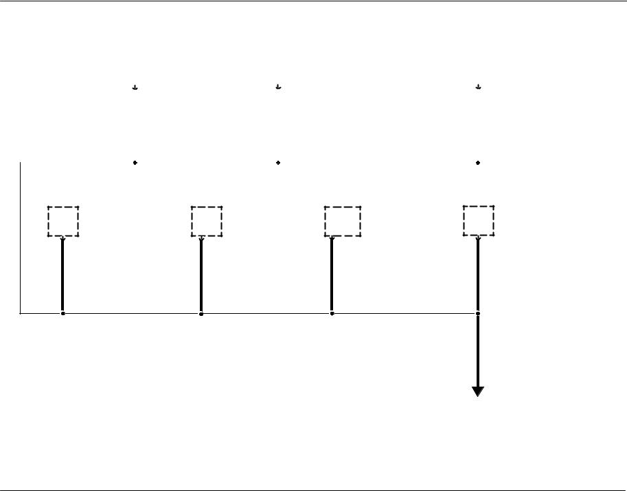
G101
Brake fluid level |
|
|
|
|
|
|
|
|
|
Speed control |
|
|
|
|
|
|
|
|
|
Headlamp, left |
|
|
|
|
|
|
|
|
|
Door lock actua- |
|
|
|
|
|
|
|
|
|
Master window |
|
|
|
|
|
|
|
|
|
Function selec- |
|
|
|
|
|
|
|
|
|
|
|
|
|
|
|
|
|
|
|
|
|
|
|
|
|
|
|
|
|
|
|
|
|
|
|
|
|
|
|
|
|
|
|
|
|
|
switch (2L414) |
|
On/Off switch |
(13008) |
|
|
tor, left front |
|
adjust switch |
|
|
tor switch as- |
||
ends in harness |
|
60−2 |
|
|
31−2 |
|
85−2 |
|
|
110−1 |
|
100−1 |
|
|
sembly |
||
|
|
B |
C124 |
7 |
C2178 |
B |
C1021 |
|
6 |
C552 |
3 |
C504 |
A |
C294b |
(19B888) |
||
|
|
|
54−1 |
||||||||||||||
|
|
|
|
|
|
|
|
|
|
|
|
|
|
|
|
|
|
57 |
BK |
57 |
BK |
|
57 |
BK |
|
57 |
BK |
|
57 |
BK |
57 |
BK |
57 |
BK |
|
|
|
|
|
|
|
|
|
|
|
|
13 |
|
1 |
C211 |
|
|
|
|
|
|
|
|
|
|
|
|
|
|
57 |
BK |
57 |
BK |
|
|
|
|
|
|
|
|
|
|
|
|
|
|
|
S207 |
|
|
|
|
|
|
|
|
|
|
|
|
|
|
|
|
57 |
BK |
|
|
|
|
|
|
|
|
|
|
|
|
|
|
|
|
|
|
|
|
|
S206 |
|
|
|
Park/turn lamp, |
|
Fog lamp, right |
|
Fog lamp, left |
|
Park/turn lamp, |
Run/Accessory |
|
|
|
|||||
|
|
right front |
|
|
front (15200) |
|
|
front (15200) |
|
left front (13411) |
relay |
|
|
|
|||
|
|
(13411) |
|
|
86−1 |
|
|
86−1 |
|
|
90−4 |
|
60−3 |
|
|
|
|
3 |
C1043 |
90−4 |
|
2 |
C162 |
|
2 |
C152 |
|
3 |
C1023 |
2 |
C2312 |
|
|
|
|
|
|
|
|
|
|
|
|
||||||||||
57 |
BK |
|
|
57 |
BK |
|
57 |
BK |
|
57 |
BK |
57 |
BK |
|
57 |
BK |
|
|
|
|
|
|
|
|
|
|
|
|
|
|
S205 |
|
|
|
|
|
|
|
|
|
|
|
|
|
|
|
|
57 |
BK |
|
|
|
|
|
|
|
|
|
|
|
|
|
|
|
|
|
|
|
|
G101 |
|
|
|
|
|
|
|
|
|
|
|
|
|
|
|
|
|
151−12 |
|
10 -5 Grounds
G102, G400
with 137” wheel- base


 Pusher fan
54−4
B C1529
85
57 BK 57 BK
not used |
|
|
|
|
|
|
|
|
|
|
|
|
|
|
|
License plate |
|
|||
|
|
|
|
|
|
|
|
|
|
|
|
|
|
|
lamp (13550) |
|
|
|||
|
|
|
|
|
|
|
|
|
|
|
|
|
|
|
|
|
|
|
||
4 |
C431 |
|
|
|
|
|
|
|
|
|
|
|
|
|
|
|
92−1 |
|
|
|
|
|
|
|
|
|
|
|
|
|
|
|
|
|
|
|
|
|
|
||
|
|
with dual tanks |
|
|
|
|
|
|
|
|
|
|
|
|
1 |
C4046b |
|
|
|
|
|
|
|
Fuel sender, |
|
|
Fuel sender, |
|
|
Reversing |
|
|
Tail lamp, left |
|
|
Tail lamp, |
|||||
4 |
C423 |
|
secondary |
|
|
|
primary |
|
|
alarm speaker |
|
90−3 |
|
|
|
right |
||||
|
49−2 |
|
|
|
49−2, 49−3 |
|
|
93−1 |
|
|
|
|
|
|
90−3 |
|||||
|
|
|
|
|
|
|
|
|
|
|
|
|
|
|||||||
|
|
B |
C3263 |
|
|
B |
C3262 |
|
|
B |
C4015 |
|
1 |
C412 |
|
|
1 |
C415 |
|
|
57 |
BK |
57 |
BK |
|
|
57 |
BK |
|
|
|
57 |
BK |
|
57 |
BK |
57 |
BK |
57 |
BK |
|
|
|
|
|
|
|
|
|
with 137” wheel- |
B |
C422 |
|
|
|
|
|
1 |
C421 |
with 137” wheel- |
||
|
|
|
|
|
|
|
|
base |
|
|
|
|
|
|
|
base |
||||
|
|
|
|
|
|
|
|
|
|
|
|
|
|
|
|
|
|
|
||
|
|
|
|
|
|
|
|
|
|
|
|
|
|
|
|
|
|
|
S401 |
|
|
|
|
|
|
|
|
|
|
|
|
|
|
|
|
|
|
|
57 |
BK |
|
|
|
|
|
|
|
|
|
|
|
|
Automatic |
|
Output Shaft |
|
Speed sen- |
|
|
|
||
|
|
|
|
|
|
|
|
|
|
|
transmission |
|
Speed (OSS) |
|
sor assembly |
|
|
|||
|
|
|
|
|
|
|
|
|
|
|
module (7G422) |
|
sensor |
|
(7M101) |
9 |
C311 |
|
||
|
|
|
|
|
|
|
|
|
|
|
29−2 |
|
|
|
|
|||||
|
|
|
|
|
|
|
|
|
|
|
|
|
(7H103) |
|
29−2 |
|
||||
|
|
|
|
|
|
|
|
|
|
C168 |
|
|
C193 |
C143 |
|
|
|
|||
84 |
|
83 |
65 |
|
62 |
|
33 |
|
3 |
|
3 |
29−2 |
2 |
|
|
|
|
|||
57 |
BK |
57 BK |
57 |
BK |
57 |
BK |
57 |
BK |
57 |
BK |
|
57 |
BK |
|
57 |
BK |
|
57 |
BK |
See page |
|
|
|
|
S109 |
|
|
|
|
|
|
|
|
|
|
|
|
|
|
|
10−6 |
|
|
|
|
|
|
|
|
|
|
|
|
|
|
|
|
|
|
|
C |
|
|
|
|
|
|
|
|
|
|
|
|
|
|
|
|
|
|
|
|
|
|
|
|
|
57 |
BK |
|
|
|
|
|
|
|
|
|
|
|
|
|
|
|
|
|
|
|
|
|
|
|
|
|
|
|
|
|
|
|
|
|
|
|
S108 |
|
|
|
|
|
|
|
|
|
|
|
|
|
|
|
|
|
|
|
57 |
BK |
57 BK |
|
|
|
|
|
|
|
|
|
|
|
|
|
|
|
|
|
|
|
|
G102 |
|
|
|
|
|
|
|
|
|
|
|
|
|
|
|
|
|
|
|
|
151−16 |
|
|
|
|
|
|
|
|
|
|
|
|
Grounds |
10 -6 |
|
G105 |
|
|
|
|
|
|
|
|
|
|
|
|
|
|
|
|
|
|
|
|
|
|
|
|
|
|
|
Power Distribu- |
|
|
Fuel heater |
|
|
|
Transmission |
|
|
Fog lamp relay |
|
Windshield wip- |
tion Center |
|||
|
relay |
|
|
|
relay |
|
|
|
86−1 |
|
|
er relay |
(PDC) |
|
|
49−1 |
|
|
|
29−1 |
|
|
|
|
|
|
81−1 |
11−1, 151−22 |
|
2 |
C1329 |
|
|
2 |
C1520 |
|
2 |
C1007 |
|
86 |
C1491 |
|
|
|
57 |
BK |
|
|
57 |
BK |
|
57 |
BK |
|
|
57 |
BK |
|
|
|
|
|
|
|
|
|
|
|
|
|
|
|
|
S104 |
|
Horn (13832) |
|
A/C clutch field |
A/C Compres- |
|
|
|
Engine Con- |
|
|
|
|||
|
44−1 |
|
coil (19D798) |
|
sor clutch diode |
|
|
|
trol Module |
|
|
|
||
|
|
|
54−3 |
|
|
54−3 |
|
|
|
|
(ECM) |
|
|
|
|
|
|
|
|
|
|
|
|
|
|
23−1 |
|
|
|
2 |
C131 |
1 |
C100 |
|
3 |
C1086 |
|
6 |
|
7 |
C175b |
|
|
|
|
|
3027 |
RD/WH |
|
3027 |
RD/WH |
|
574 |
BK/PK |
574 |
BK/PK |
|
|
|
|
|
|
|
|
|
S102 |
|
|
|
|
|
|
|
|
|
|
|
|
See page |
See page |
|
|
|
|
|
|
|
||
|
|
|
|
10−7 |
|
10−7 |
|
|
|
|
|
|
|
|
|
|
|
|
|
D |
|
E |
|
|
|
|
|
|
|
57 |
BK |
3027 |
RD/WH |
51 |
BK/WH |
57 |
BK |
|
|
|
57 |
BK |
57 |
BK |
|
|
7 |
|
1 |
|
4 |
C140 |
|
|
|
|
|
|
|
|
|
|
|
574 |
BK/PK |
574 |
BK/PK |
|
|
|
|
|
|
|
|
|
|
|
|
|
|
|
|
|
|
S105 |
|
|
|
|
|
57 |
BK |
|
|
574 |
BK/PK |
|
|
|
|
|
|
|
|
|
|
|
|
|
|
|
|
|
|
|
S101 |
|
|
|
|
|
|
|
|
|
|
|
|
|
57 |
BK |
|
|
|
|
|
|
|
|
|
|
|
|
|
|
C |
|
|
|
|
|
|
|
|
|
|
|
|
|
See page |
|
|
|
|
|
|
|
|
|
|
|
|
|
|
10−5 |
|
|
G105 |
|
|
|
|
|
|
|
|
|
|
|
|
|
|
|
|
|
|
|
|
|
|
|
|
|
|
|
|
|
151−22 |
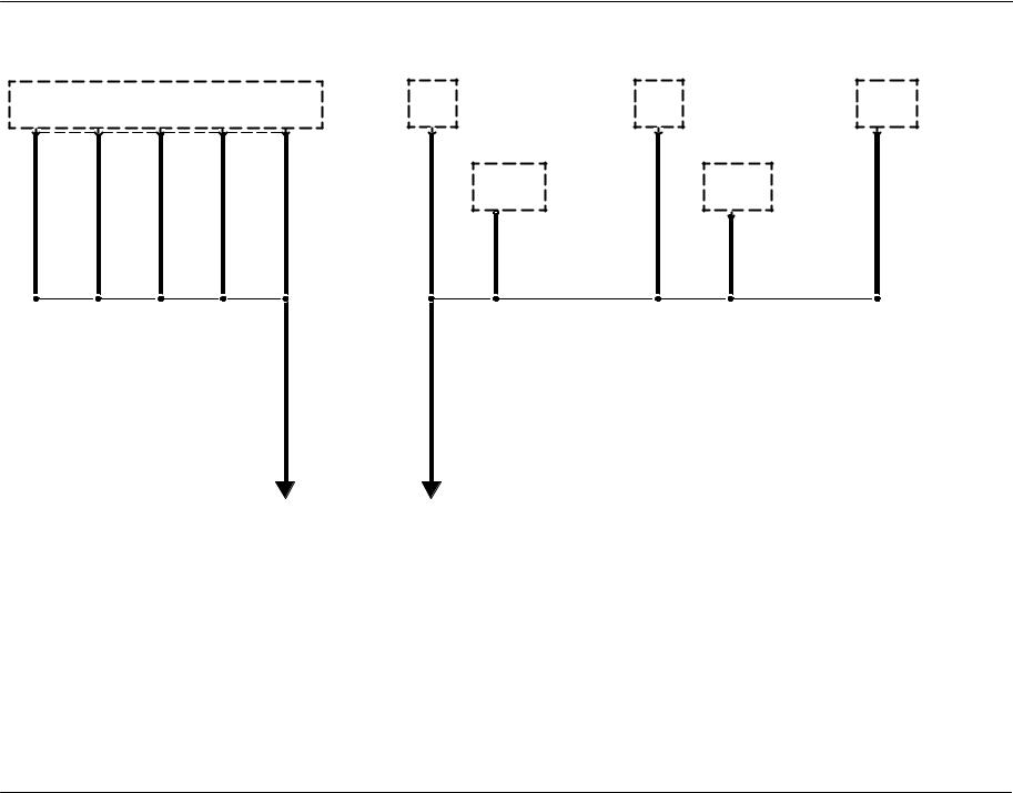
10 -7 Grounds
|
|
|
|
|
Injector Driv- |
|
EGR system |
|
|
Glow plug |
|
Mass Air Flow |
||
|
|
|
|
|
er Module |
|
module |
|
|
|
relay |
|
|
(MAF) sensor |
|
|
|
|
|
(IDM) |
|
23−2 |
|
|
|
23−9 |
|
|
(12B579) |
|
|
|
|
|
23−4 |
|
|
|
|
|
|
|
|
23−6 |
1 |
2 |
3 |
22 |
26 |
C1174c |
2 |
C1450 |
|
1 |
C1084d |
|
C |
C128 |
|
51 |
BK/WH |
51 |
BK/WH |
51 |
BK/WH |
|
|
Manifold in- |
|
|
|
|
Boost control |
|
|
51 BK/WH |
|
51 |
BK/WH |
|
57 |
BK |
|
|
|
|
|
||
|
|
|
take air heater |
|
|
|
|
solenoid |
|
|||||
|
|
|
|
|
|
|
|
|
|
|
|
|
||
|
|
|
|
|
|
|
|
relay |
|
|
|
|
23−5 |
|
|
|
|
|
|
|
|
1 |
23−3 |
|
|
1 |
C1515 |
|
|
|
|
|
|
|
|
|
C1245d |
|
|
|
|
|||
|
|
|
|
|
|
|
57 |
BK |
57 |
BK |
57 |
BK |
57 |
BK |
|
|
|
|
|
S106 |
|
|
|
|
|
|
|
|
S107 |
51 BK/WH |
57 BK |
|
|
E |
D |
||
See page |
See page |
|
10−6 |
10−6 |
|
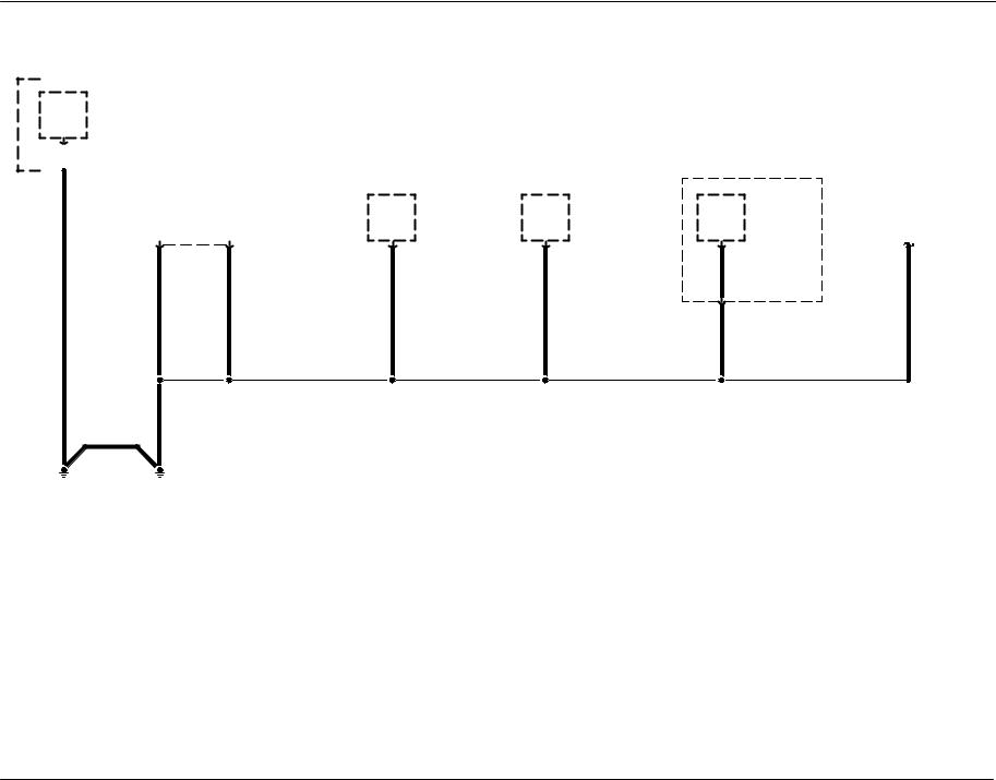
Grounds 10 -8
G103, G104
|
|
|
|
|
|
|
|
|
|
|
|
|
|
|
|
|
|
|
|
Power Distribu- |
|
|
|
|
|
|
|
|
|
|
|
|
|
|
|
|
|||||||||
|
|
|
|
|
|
Body builder |
|
|
|
|
|
|
|
|
|
|
|
|
|
|
|
|
|
||||||||||||||||||||||
|
|
|
|
|
|
|
|
|
|
|
|
|
|
|
|
|
|
|
|
|
|
|
|||||||||||||||||||||||
|
|
|
|
|
|
|
tion Center |
|
|
|
|
|
|
|
|
|
|
|
|
|
|
|
|
||||||||||||||||||||||
|
|
|
|
|
|
|
|
|
|
|
|
|
|
|
|
|
|
|
|
|
|
|
|||||||||||||||||||||||
|
|
|
|
|
|
relay #1 |
|
(PDC) |
|
|
|
|
|
|
|
|
|
|
|
|
|
|
|
|
|||||||||||||||||||||
|
|
|
|
|
|
|
|
|
|
|
|
|
|
|
|
|
|
|
|
|
|
|
|||||||||||||||||||||||
|
|
|
|
|
|
140−1 |
|
11−1, 151−22 |
|
|
|
|
|
|
|
|
|
|
|
|
|
|
|
|
|||||||||||||||||||||
|
|
|
|
|
|
|
|
|
|
|
|
|
|
|
|
|
|
|
|
|
|
|
|||||||||||||||||||||||
2 |
|
C1519 |
|
|
|
|
|
|
|
|
|
|
|
|
|
|
|
|
|
|
|
|
|
|
|
|
|
|
|
||||||||||||||||
|
|
|
|
|
|
|
|
|
|
|
|
|
|
|
|
|
|
|
|
|
|
|
|
|
|
|
|
||||||||||||||||||
|
|
|
|
|
|
|
|
|
|
|
|
|
|
|
|
|
|
|
|
|
|
|
|
|
|
|
|
||||||||||||||||||
|
|
|
|
|
|
|
|
|
|
|
|
|
|
|
with dual tanks |
|
|||||||||||||||||||||||||||||
|
|
|
|
|
|
|
|
|
|
|
|
|
|
|
|
|
|
|
|
|
|
|
|
|
|
|
|
|
|
|
|
|
|
||||||||||||
|
|
|
|
|
|
|
|
|
|
|
|
|
|
|
|
|
|
|
|
|
|
|
|
|
|
|
|
|
|
|
|
|
|
|
|
|
|
|
|
|
|
|
|
|
|
|
|
|
|
|
|
|
|
|
|
|
|
|
|
|
|
|
|
|
|
|
|
|
|
|
|
|
|
|
ABS control |
Fuel pump |
Fuel heater |
|
|
|
|
|
|
|
|
Fuel transfer |
|||||
|
|
|
|
|
|
|
|
|
|
|
|
|
|
|
|
|
|
|
|
|
|
|
|
|
|
|
|
|
|||||||||||||||||
|
|
|
|
|
|
|
|
|
|
|
|
|
|
|
|
|
|
|
|
|
|
|
|
|
|
|
|
|
module |
49−3 |
49−1 |
|
|
|
|
|
|
|
|
pump |
|||||
|
|
|
|
|
|
|
|
|
|
|
|
|
|
|
|
|
|
|
|
|
|
|
|
|
|
|
|
|
|||||||||||||||||
|
|
|
|
|
|
|
|
|
|
|
|
|
|
|
|
|
|
|
|
|
|
|
|
|
|
|
|
|
(2C219) |
|
|
|
|
|
|
|
|
|
|
49−2 |
|||||
|
|
|
|
|
|
|
|
|
|
|
|
|
|
|
|
|
|
|
|
|
|
|
|
|
|
|
|
|
|
|
|||||||||||||||
|
|
|
|
|
|
|
|
|
|
|
|
|
|
|
|
|
|
|
|
|
|
|
|
|
|
|
|
|
42−1 |
|
|
|
|
|
|
|
|
|
|
|
|
|
|
|
|
|
|
16 |
|
45 |
C135 |
2 |
C1253 |
1 |
C1076 |
D |
C3264 |
57 |
BK |
530 |
LG/YE |
57 |
BK |
57 |
BK |
57 |
BK |
57 |
BK |
|
|
|
|
|
|
|
|
|
|
23 |
C311 |
|
|
|
|
|
|
|
|
|
|
57 |
BK |
|
|
57 |
BK |
|
|
|
|
|
|
|
|
|
57 |
|
|
|
|
|
|
|
|
|
|
|
BK |
|
|
|
|
|
|
|
|
|
|
|
G104 |
|
G103 |
|
|
|
|
|
|
|
|
|
151−23 |
|
151−16 |
|
|
|
|
|
|
|
|
ends in harness
57 BK
 S100
S100
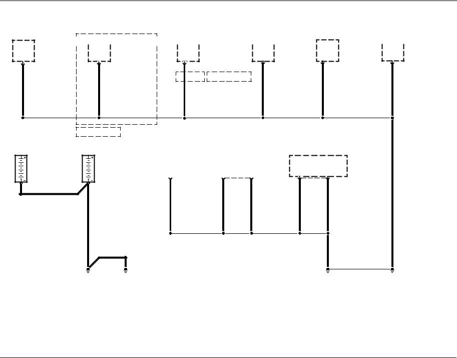
10 -9 Grounds
G107, G108, G200
Daytime Run- |
|
|
|
|
|
|
|
|
|
|
Audio unit |
|
|
|
|
|
|
|
|
|
|
Audio unit |
|
|
|
|
|
|
|
|
|
Remote keyless |
Door lock timer |
|
|
|
|
|
|
|
|
|
Instrument clus- |
|
ning Lamps |
|
(18808) |
|
|
|
(18808) |
|
|
|
|
entry module |
|
117−2 |
ter (10849) |
||||
|
(DRL) module |
|
130−1 |
|
|
|
130−1 |
|
|
|
|
(15K602) |
|
|
|
|
60−2 |
||
|
97−2 |
|
|
|
|
|
|
|
|
|
|
|
|
117−1 |
|
|
|
|
|
D |
C1030 |
|
C |
C290 |
|
8 |
C240 |
|
|
|
|
14 |
C272 |
|
5 |
C2333 |
1 |
C220b |
|
|
|
|
|
|
|
5 |
C2188 |
Cassette |
|
|
|
|
|
|
|
|
|
||
57 |
BK |
|
57 |
BK |
|
57 |
BK |
|
|
|
|
57 |
BK |
|
|
57 |
BK |
57 |
BK |
|
|
|
|
|
|
|
|
|
|
|
|
|
|
|
|
|
|
|
S200 |
|
|
|
premium radio |
|
|
|
|
|
|
|
|
|
|
|
|
|
|
|
|
|
Battery 2 |
|
|
Battery (10655) |
Engine diagnostic |
|
Data Link Connector |
|
|
|
|
|
Instrument clus- |
|
|||||
|
151−18 |
|
|
151−18 |
|
|
|
|
|
|
ter (10849) |
|
|||||||
|
|
|
connector |
|
|
|
(DLC) (14489) |
|
|
|
|
|
|
|
|||||
|
|
|
|
|
|
|
|
|
|
|
|
|
|
60−2 |
|
||||
|
|
|
|
|
14−1 |
|
|
|
14−2 |
|
|
|
|
|
|
|
|
||
|
|
|
|
|
|
|
|
|
|
|
|
|
|
|
|
|
|||
|
C1249b |
|
C1100b |
A |
C2173 |
|
|
4 |
|
5 |
C251 |
2 |
|
3 |
C220b |
|
|
||
|
BK |
|
|
|
|
|
|
|
|
|
|
|
|
|
|
|
|||
|
|
|
BK |
57 |
BK |
|
|
57 |
BK |
57 |
BK |
|
57 |
BK |
57 |
BK |
57 |
BK |
|
|
|
|
|
|
|
|
|
|
|
|
|
|
|
|
|
|
S201 |
|
|
|
|
|
|
|
|
|
|
|
|
|
|
|
|
|
|
57 |
BK |
|
|
|
|
|
|
BK |
|
|
|
|
|
|
|
|
|
|
|
|
|
|
|
|
|
|
G107 |
G108 |
|
|
|
|
|
|
|
|
|
|
|
|
|
G200 |
|
|
|
|
|
|
|
|
|
|
|
|
|
|
|
|
|
|
|
|
151−12 |
 Loading...