


Intel S1200BTL Motherboard

Intel® Server Board S1200BT
Revision 2.4
May, 2013
Enterprise Platforms and Services Division
Technical Product Specification
Intel order number G13326-007

Revision History Intel® Server Board S1200BT TPS
ii
Date
Revision
Number
Modifications
July 2010
0.3
Initial release.
November 2010
0.5
Updated the hardware info and SE SKU.
January 2011
0.7
Updated S1200BTS info and BIOS setup page.
January 2011
0.9
Updated S1200BT video mode.
March 2011
1.0
Corrected typos.
September 2011
1.1
Corrected typos.
February 2012
2.0
Updated the E3-1200 v2 processors support.
Added a note in chapter 1.
June 2012
2.1
Add S1200BTLRM SKU in S1200BT family.
Add Intel® ROC module support on S1200BTLRM.
Add BIOS new feature.
February 2013
2.2
Updated Disclaimers.
SAS Mezzanine connectors.
March 2013
2.3
Updated section 3.8 title and section 3.8.1
May 2013
2.4
Updated MTBF value
Revision History
Intel order number G13326-007 Revision 2.4

Intel® Server Board S1200BT TPS Disclaimers
iii
Disclaimers
INFORMATION IN THIS DOCUMENT IS PROVIDED IN CONNECTION WITH INTEL PRODUCTS. NO LICENSE,
EXPRESS OR IMPLIED, BY ESTOPPEL OR OTHERWISE, TO ANY INTELLECTUAL PROPERTY RIGHTS IS
GRANTED BY THIS DOCUMENT. EXCEPT AS PROVIDED IN INTEL'S TERMS AND CONDITIONS OF SALE FOR
SUCH PRODUCTS, INTEL ASSUMES NO LIABILITY WHATSOEVER AND INTEL DISCLAIMS ANY EXPRESS OR
IMPLIED WARRANTY, RELATING TO SALE AND/OR USE OF INTEL PRODUCTS INCLUDING LIABILITY OR
WARRANTIES RELATING TO FITNESS FOR A PARTICULAR PURPOSE, MERCHANTABILITY, OR
INFRINGEMENT OF ANY PATENT, COPYRIGHT OR OTHER INTELLECTUAL PROPERTY RIGHT.
A "Mission Critical Application" is any application in which failure of the Intel Product could result, directly or indirectly,
in personal injury or death. SHOULD YOU PURCHASE OR USE INTEL'S PRODUCTS FOR ANY SUCH MISSION
CRITICAL APPLICATION, YOU SHALL INDEMNIFY AND HOLD INTEL AND ITS SUBSIDIARIES,
SUBCONTRACTORS AND AFFILIATES, AND THE DIRECTORS, OFFICERS, AND EMPLOYEES OF EACH,
HARMLESS AGAINST ALL CLAIMS COSTS, DAMAGES, AND EXPENSES AND REASONABLE ATTORNEYS'
FEES ARISING OUT OF, DIRECTLY OR INDIRECTLY, ANY CLAIM OF PRODUCT LIABILITY, PERSONAL
INJURY, OR DEATH ARISING IN ANY WAY OUT OF SUCH MISSION CRITICAL APPLICATION, WHETHER OR
NOT INTEL OR ITS SUBCONTRACTOR WAS NEGLIGENT IN THE DESIGN, MANUFACTURE, OR WARNING OF
THE INTEL PRODUCT OR ANY OF ITS PARTS.
Intel may make changes to specifications and product descriptions at any time, without notice. Designers must not
rely on the absence or characteristics of any features or instructions marked "reserved" or "undefined". Intel reserves
these for future definition and shall have no responsibility whatsoever for conflicts or incompatibilities arising from
future changes to them. The information here is subject to change without notice. Do not finalize a design with this
information.
The products described in this document may contain design defects or errors known as errata which may cause the
product to deviate from published specifications. Current characterized errata are available on request.
Contact your local Intel sales office or your distributor to obtain the latest specifications and before placing your
product order.
Copies of documents which have an order number and are referenced in this document, or other Intel literature, may
be obtained by calling 1-800-548-4725, or go to: http://www.intel.com/design/literature.
Revision 2.4 Intel order number G13326-007

Table of Contents Intel® Server Board S1200BT TPS
iv
Table of Contents
1. Introduction ........................................................................................................................ 1
1.1 Chapter Outline ...................................................................................................... 1
1.2 Server Board Use Disclaimer ................................................................................. 2
2. Overview ................................ ................................................................ ............................. 3
2.1 Intel® Server Board S1200BT Feature Set.............................................................. 3
2.2 Server Board Layout .............................................................................................. 6
2.2.1 Server Board Connector and Component Layout ................................................... 7
2.2.2 Intel® Server Board S1200BTL/S1200BTLRM Mechanical Drawings ................... 10
2.2.3 Server Board Rear I/O Layout .............................................................................. 14
3. Functional Architecture ................................................................................................... 15
3.1 Processor Sub-System ......................................................................................... 16
3.1.1 Intel® Xeon® Processor E3-1200 Processors and Intel® Xeon® E3-1200 V2
Processors ......................................................................................................................... 17
3.1.2 The 2nd Generation Intel® Core™ i3 Processors and the 3rd Generation Intel®
Core™ i3 Processors ......................................................................................................... 17
3.1.3 Intel® Turbo Boost Technology ............................................................................. 17
3.2 Memory Subsystem.............................................................................................. 18
3.2.1 Memory Supported ............................................................................................... 18
3.2.2 Post Error Codes .................................................................................................. 19
3.2.3 Memory Map and Population Rules ...................................................................... 20
3.2.4 Publishing System Memory .................................................................................. 22
3.2.5 Memory RAS Support .......................................................................................... 22
3.3 Intel® Chipset PCH ............................................................................................... 23
3.4 I/O Sub-system .................................................................................................... 23
3.4.1 Digital Media Interface (DMI) ................................................................................ 23
3.4.2 PCI Express* Interface ......................................................................................... 23
3.4.3 Serial ATA Support .............................................................................................. 24
3.4.4 Low Pin Count (LPC) Interface ............................................................................. 25
3.4.5 USB 2.0 Support .................................................................................................. 25
3.5 Optional Intel® SAS RAID Module ........................................................................ 26
3.6 Optional Intel® ROC Module ................................................................................. 26
3.7 Integrated Baseboard Management Controller ..................................................... 26
3.7.1 Integrated BMC LAN Channels ............................................................................ 28
3.7.2 Optional RMM4 Advanced Management Board .................................................... 29
3.7.3 Serial Ports .......................................................................................................... 29
3.7.4 Floppy Disk Controller .......................................................................................... 29
3.7.5 Keyboard and Mouse Support .............................................................................. 30
3.7.6 Wake-up Control .................................................................................................. 30
3.8 Graphic Support ................................................................................................... 30
Intel order number G13326-007 Revision 2.4

Intel® Server Board S1200BT TPS Table of Contents
v
3.8.1 Intel® Server Board S1200BTL/S1200BTLRM ...................................................... 30
3.8.2 Video for Intel® Server Board S1200BTS ............................................................. 31
3.9 Network Interface Controller (NIC) ....................................................................... 31
3.9.1 Gigabit Ethernet Controller 82574L ...................................................................... 31
3.9.2 Gigabit Ethernet PHY 82579 ................................................................................ 31
3.9.3 MAC Address Definition ....................................................................................... 32
3.10 Intel® I/O Acceleration Technolgy 2 (Intel® I/OAT2) .............................................. 32
3.10.1 Direct Cache Access (DCA) ................................................................................. 32
3.11 Intel® Virtualization Technology for Directed I/O (Intel® VT-d) ............................... 32
3.12 TPM (Trusted Platform Module) ........................................................................... 32
4. Platform Management ...................................................................................................... 34
4.1 Feature Support ................................................................................................... 35
4.1.1 IPMI 2.0 Features ................................................................................................. 35
4.1.2 Non-IPMI Features ............................................................................................... 35
4.1.3 New Manageability Features ................................................................................ 36
4.2 Basic and Optional Advanced Management Features .......................................... 37
4.2.1 Enabling Advanced Management Features .......................................................... 38
4.2.2 Keyboard, Video, and Mouse (KVM) Redirection ................................................. 38
4.2.3 Media Redirection ................................................................................................ 40
4.2.4 Embedded Web server ......................................................................................... 41
4.2.5 Embedded Platform Debug .................................................................................. 42
4.2.6 Data Center Management Interface (DCMI) ......................................................... 43
4.2.7 Local Directory Authentication Protocol (LDAP) ................................................... 43
4.3 Thermal Control ................................................................................................... 43
4.3.1 Memory Thermal Throttling .................................................................................. 43
4.3.2 Fan Speed Control ............................................................................................... 44
4.4 Intel® Intelligent Power Node Manager ................................................................. 44
4.4.1 Overview .............................................................................................................. 44
4.4.2 Features ............................................................................................................... 45
4.4.3 Role of Integrated BMC in NM .............................................................................. 46
5. Server Management Capability for Intel® Server Board S1200BTS ............................... 47
5.1 Supper I/O ............................................................................................................ 47
5.1.1 Key Features of supper I/O .................................................................................. 47
6. BIOS User Interface .......................................................................................................... 48
6.1 BIOS POST Initialization ...................................................................................... 48
6.1.1 BIOS Revision Identification ................................................................................. 48
6.2 HotKeys Supported During POST ........................................................................ 49
6.3 POST Logo Screen/Diagnostic Screen................................................................. 50
6.4 BIOS Boot Pop-up Menu ...................................................................................... 50
6.5 BIOS Setup Utility ................................................................................................ 51
6.5.1 BIOS Setup Operation .......................................................................................... 51
Revision 2.4 Intel order number G13326-007

Table of Contents Intel® Server Board S1200BT TPS
vi
6.5.2 BIOS Setup Utility Screens................................................................................... 54
7. Connector/Header Locations and Pin-outs .................................................................... 95
7.1 Board Connector Information ............................................................................... 95
7.2 Power Connectors ................................................................................................ 96
7.3 System Management Headers ............................................................................. 97
7.3.1 Intel® Remote Management Module 4 (Intel® RMM4) Lite connetor and Dedicated
NIC connector .................................................................................................................... 97
7.3.2 LPC/IPMB Header ................................................................................................ 98
7.3.3 HSBP Header....................................................................................................... 98
7.3.4 SGPIO Header ..................................................................................................... 98
7.4 Front Control Panel Connector ............................................................................. 98
7.4.1 Power Button........................................................................................................ 99
7.4.2 Reset Button ........................................................................................................ 99
7.4.3 System Status Indicator LED .............................................................................. 100
7.5 I/O Connectors ................................................................................................... 101
7.5.1 VGA Connector .................................................................................................. 101
7.5.2 Rear NIC and USB connector ............................................................................ 101
7.5.3 SATA ................................................................................................................. 102
7.5.4 SAS Mezzanine Connectors ............................................................................... 102
7.5.5 Serial Port Connectors ....................................................................................... 103
7.5.6 USB Connector .................................................................................................. 103
7.6 PCI Express* Slot/PCI Slot/Riser Card Slot ........................................................ 104
7.7 Fan Headers ...................................................................................................... 108
8. Jumper Blocks ................................................................................................................ 109
8.1 CMOS Clear and Password Reset Usage Procedure ......................................... 111
8.1.1 Clearing the CMOS ............................................................................................ 111
8.1.2 Clearing the Password ....................................................................................... 111
8.2 Integrated BMC Force Update Procedure (for The Intel® Server Board
S1200BTL/S1200BTLRM) ................................................................................................... 112
8.3 ME Force Update Jumper .................................................................................. 112
8.4 BIOS Recovery Jumper ...................................................................................... 113
9. Intel® Light Guided Diagnostics .................................................................................... 114
9.1 System Status LED (For S1200BTL/S1200BTLRM) ........................................... 114
9.2 Post Code Diagnostic LEDs ............................................................................... 114
10. Design and Environmental Specifications .................................................................... 116
10.1 Intel® Server Board S1200BT/S1200BTLRM Design Specifications ................... 116
10.2 Board-level Calculated MTBF ............................................................................. 116
10.2.1 Processor Power Support................................................................................... 117
10.3 Power Supply Output Requirements ................................ .................................. 117
10.3.1 Grounding .......................................................................................................... 118
10.3.2 Standby Outputs ................................................................................................ 118
Intel order number G13326-007 Revision 2.4

Intel® Server Board S1200BT TPS Table of Contents
vii
10.3.3 Remote Sense ................................................................................................... 118
10.3.4 Voltage Regulation ............................................................................................. 118
10.3.5 Dynamic Loading ............................................................................................... 118
10.3.6 Capacitive Loading ............................................................................................. 119
10.3.7 Closed-loop Stability........................................................................................... 119
10.3.8 Common Mode Noise ......................................................................................... 119
10.3.9 Ripple/Noise ....................................................................................................... 119
10.3.10 Timing Requirements ......................................................................................... 119
10.3.11 Residual Voltage Immunity in Standby Mode ..................................................... 121
10.3.12 Protection Circuits ................................ .............................................................. 122
Appendix A: Integration and Usage Tips ............................................................................ 123
Appendix B: Integrated BMC Sensor Tables ....................................................................... 124
Appendix C: POST Code Diagnostic LED Decoder ............................................................ 134
Appendix D: POST Code Errors ........................................................................................... 138
Appendix E: Supported Intel® Server Chassis .................................................................... 141
Glossary ................................................................................................................................ 142
Reference Documents .......................................................................................................... 146
Revision 2.4 Intel order number G13326-007

List of Figures Intel® Server Board S1200BT TPS
viii
List of Figures
Figure 1. Intel® Server Board S1200BTL/S1200BTLRM .............................................................. 6
Figure 2. Intel® Server Board S1200BTS .................................................................................... 7
Figure 3. Intel® Server Board S1200BTL/S1200BTLRM Layout .................................................. 8
Figure 4. Intel® Server Board S1200BTS Layout ......................................................................... 9
Figure 5. Intel® Server Board S1200BTL/S1200BTLRM – Hole and Component Positions ....... 10
Figure 6. Intel® Server Board S1200BTL/S1200BTLRM – Major Connector Pin Location (1 of 2)11
Figure 7. Intel® Server Board S1200BTL/S1200BTLRM – Major Connector Pin Location (2 of 2)12
Figure 8. Intel® Server Board S1200BTL/S1200BTLRM – Primary Side Keepout Zone ............ 13
Figure 9. Intel® Server Board S1200BTL/S1200BTLRM – Secondary Side Keepout Zone ........ 13
Figure 10. Intel® Server Board S1200BT Rear I/O Layout ......................................................... 14
Figure 11. Intel® Server Board S1200BTL/S1200BTLRM Functional Block Diagram ................. 15
Figure 12. Intel® Server Board S1200BTS Functional Block Diagram ....................................... 16
Figure 13. Integrated BMC Hardware ........................................................................................ 27
Figure 14. Server Management Bus (SMBUS*) Block Diagram ................................................ 34
Figure 15. Main Screen ............................................................................................................. 57
Figure 16. Advanced Screen ..................................................................................................... 60
Figure 17. Processor Configuration Screen (S1200BT) ............................................................. 62
Figure 18. Memory Configuration Screen .................................................................................. 69
Figure 19. Mass Storage Controller Configuration Screen ........................................................ 71
Figure 20. Serial Port Configuration Screen .............................................................................. 74
Figure 21. USB Configuration Screen ....................................................................................... 74
Figure 22. PCI Configuration Screen ......................................................................................... 75
Figure 23. System Acoustic and Performance Configuration ..................................................... 76
Figure 24. Security Screen ........................................................................................................ 78
Figure 25. Server Management Screen (S1200BTL/S1200BTLRM) ......................................... 81
Figure 26. Server Management Screen (S1200BTS) ................................................................ 82
Figure 27. Console Redirection Screen ..................................................................................... 82
Figure 28. System Information Screen (S1200BTL/S1200BTLRM) ........................................... 83
Figure 29.System Information Screen (S1200BTS) ................................................................... 84
Figure 30. BMC LAN Configuration Screen (S1200BTL/S1200BTLRM) .................................... 85
Figure 31. Hardware Monitor Screen, Auto Fan Control (S1200BTS) ....................................... 86
Figure 32. Hardware Monitor Screen, Manual Fan Control (S1200BTS) ................................... 86
Figure 33. Real-time Teperature and Voltage Status Screen (S1200BTS) ................................ 87
Figure 34. Boot Options Screen ................................................................................................ 88
Figure 35. Hard Disk Order Screen ........................................................................................... 89
Figure 36. CDROM Order Screen ............................................................................................. 89
Figure 37. Floppy Order Screen ................................................................................................ 90
Figure 38. Network Device Order Screen .................................................................................. 90
Figure 39. BEV Device Order Screen ........................................................................................ 91
Intel order number G13326-007 Revision 2.4

Intel® Server Board S1200BT TPS List of Figures
ix
Figure 40. Add EFI Boot Option Screen .................................................................................... 91
Figure 41. Delete EFI Boot Option Screen ................................................................................ 92
Figure 42. Boot Manager Screen .............................................................................................. 92
Figure 43. Error Manager Screen .............................................................................................. 93
Figure 44. System Event Log Screen (S1200BTS) ................................................................... 93
Figure 45. Exit Screen ............................................................................................................... 94
Figure 46. Jumper Blocks (J4A2, J1F1, J1F3, J1F2, and J1E2) on S1200BTL/S1200BTLRM 109
Figure 47. Jumper Blocks (J2G1, J1G1, J1H3, and J2J1) on S1200BTS ................................ 110
Figure 48. POST Code Diagnostic LED Location .................................................................... 115
Figure 49. Output Voltage Timing ........................................................................................... 120
Figure 50. Turn On/Off Timing (Power Supply Signals) ........................................................... 121
Revision 2.4 Intel order number G13326-007

List of Tables Intel® Server Board S1200BT TPS
x
List of Tables
Table 1. Intel® Server Board S1200BT Feature Set ..................................................................... 3
Table 2. Major Board Components.............................................................................................. 8
Table 3. Major Board Components.............................................................................................. 9
Table 4. Memory Configuration Table ....................................................................................... 21
Table 5. UDIMM memory configuration rule for Intel® Xeon® E3-1200 Processors or the 2nd
Generation Intel® Core™ i3 Processors .............................................................................. 21
Table 6. UDIMM memory configuration rule for Intel® Xeon® E3-1200 V2 Processors or the 3rd
Generation Intel® Core™ i3 Processors .............................................................................. 22
Table 7. UDIMM Maximum configuration .................................................................................. 22
Table 8. Optional RMM4 Advanced Management Board Features ............................................ 29
Table 9. Serial B Header (J1B2 on S1200BTL/S1200BTLRM or J8A1 on S1200BTS) Pin-out .. 29
Table 10. Video Modes ............................................................................................................. 30
Table 11. Dual Video Modes ..................................................................................................... 31
Table 12. Basic and Advanced Management Features ............................................................. 37
Table 13. NM Features ............................................................................................................. 45
Table 14. POST HotKeys Recognized ...................................................................................... 49
Table 15. BIOS Setup Page Layout .......................................................................................... 52
Table 16. BIOS Setup: Keyboard Command Bar ...................................................................... 52
Table 17. Screen Map ............................................................................................................... 55
Table 18. Board Connector Matrix on S1200BTL/S1200BTLRM ............................................... 95
Table 19. Board Connector Matrix on S1200BTS ...................................................................... 96
Table 20. Baseboard Power Connector Pin-out (J9G1) ............................................................. 96
Table 21. SSI Processor 8-PIN Power Connector Pin-out (J9A1) ............................................. 97
Table 22. Intel® RMM4 lite Connector Pin-out (J4B1) ................................................................ 97
Table 23. Dedicated NIC connector for RMM4 .......................................................................... 97
Table 24. LPC/IPMB Header Pin-out (J1H5) ............................................................................. 98
Table 25. HSBP Header Pin-out (J1J2) ..................................................................................... 98
Table 26. SGPIO Header Pin-out (J1J3 on S1200BTL/S1200BTLRM and J2J2 on S1200BTS)98
Table 27. Front Panel SSI Standard 24-pin Connector Pin-out (J1C1 on
S1200BTL/S1200BTLRM or J1C2 on S1200BTS) .............................................................. 98
Table 28. System Status LED Indicator States ................................................................ ........ 100
Table 29. VGA Connector Pin-out ........................................................................................... 101
Table 30. RJ-45 10/100/1000 NIC Connector Pin-out ............................................................. 101
Table 31. RJ-45 10/100/1000 NIC Connector Pin-out (J6A1) .................................................. 101
Table 32. 6Gb/s SATA Connector Pin-Out .............................................................................. 102
Table 33. 3Gb/s SATA Connector Pin-out ............................................................................... 102
Table 34. SAS Connector Pin-out (J2H1) ................................................................................ 102
Table 35. External Serial A Port Pin-out (J8A1)....................................................................... 103
Table 36. Internal 9-pin Serial B Header Pin-out (J1B2) .......................................................... 103
Intel order number G13326-007 Revision 2.4

Intel® Server Board S1200BT TPS List of Tables
xi
Table 37. Internal USB Connector Pin-out ( J1E1 and J1D1) .................................................. 104
Table 38. Pin-out of Internal USB Connector for low-profile Smart module (J3F2) .................. 104
Table 39. Pin-out of adaptive riser slot/PCI Express slot 6 ...................................................... 104
Table 40. Three PCI Express* x8 connectors (J2B2, J3B1, and J4B2) ................................... 106
Table 41. One PCI X32 connector (J1B1) ............................................................................... 107
Table 42. SSI 4-pin Fan Header Pin-out ................................................................................. 108
Table 43. Server Board Jumpers (J1F1, J1F2, J1F3, J1E2, and J4A2) on
S1200BTL/S1200BTLRM ................................................................................................. 109
Table 44. Server Board Jumpers (J2G1, J1G1, J1H3, and J2J1) on S1200BTS ..................... 110
Table 45. Front Panel LED Behavior Summary ....................................................................... 114
Table 46. Server Board Design Specifications ........................................................................ 116
Table 47. Intel® Xeon® Processor TDP Guidelines .................................................................. 117
Table 48. 350-W Load Ratings ................................................................................................ 117
Table 49. Voltage Regulation Limits ........................................................................................ 118
Table 50. Transient Load Requirements ................................................................................. 118
Table 51. Capacitve Loading Conditions ................................ ................................................. 119
Table 52. Ripple and Noise ..................................................................................................... 119
Table 53. Output Voltage Timing ............................................................................................. 120
Table 54. Turn On/Off Timing .................................................................................................. 120
Table 55. Over-Current Protection (OCP) ............................................................................... 122
Table 56. Over-voltage Protection (OVP) Limits ...................................................................... 122
Table 57. BMC Core Sensors ................................................................ ................................. 126
Table 58. POST Progress Code LED Example ....................................................................... 134
Table 59. POST Progress Codes ............................................................................................ 134
Table 60. POST Error Codes and Messages .......................................................................... 138
Table 61. POST Error Beep Codes ......................................................................................... 140
Revision 2.4 Intel order number G13326-007

List of Tables Intel® Server Board S1200BT TPS
xii
<This page is intentionally left blank.>
Intel order number G13326-007 Revision 2.4

Intel® Server Board S1200BT TPS Introduction
1
1. Introduction
This Technical Product Specification (TPS) provides board specific information detailing the
features, functionality, and high-level architecture of the Intel® Server Board S1200BT.
In addition, you can obtain design-level information for specific subsystems by ordering the
External Product Specifications (EPS) or External Design Specifications (EDS) for a given
subsystem. EPS and EDS documents are not publicly available and must be ordered through
your local Intel® representative.
Note: The product codes of S1200BTL and S1200BTS can only support Intel® Xeon® E3-1200
Processors or the 2nd Generation Intel® Core™ i3 Processors. The product codes of
S1200BTLR, S1200BTSR, and S1200BTLRM can support Intel® Xeon® E3-1200Processors,
the 2nd Generation Intel® Core™ i3 Processors, Intel® Xeon® E3-1200 V2 processors or the 3rd
Generation Intel® Core™ i3.
1.1 Chapter Outline
This document is divided into the following chapters:
Chapter 1 – Introduction
Chapter 2 – Server Board Overview
Chapter 3 – Functional Architecture
Chapter 4 – Platform Management
Chapter 5 – Server Management Capability for Intel
Chapter 6 – BIOS User Interface
Chapter 7 – Connector/Header Locations and Pin-outs
Chapter 8 – Jumpers Blocks
Chapter 9 – Intel
Chapter 10 – Design and Environmental Specifications
Appendix A – Integration and Usage Tips
Appendix B – Integrated BMC Sensor Tables
Appendix C – POST Code Diagnostic LED Decoder
Appendix D – POST Code Errors
Appendix E – Supported Intel
Glossary
Reference Documents
®
Light-Guided Diagnostics
®
Server Chassis
®
Server Board S1200BTS
Revision 2.4 Intel order number G13326-007

Introduction Intel® Server Board S1200BT TPS
2
1.2 Server Board Use Disclaimer
Intel Corporation server boards contain a number of high-density Very Large Scale Integration
(VLSI) and power delivery components that need adequate airflow to cool. Intel® ensures
through its own chassis development and testing that when Intel® server building blocks are
used together, the fully integrated system meets the intended thermal requirements of these
components. It is the responsibility of the system integrator who chooses not to use Intel®
developed server building blocks to consult vendor datasheets and operating parameters to
determine the amount of airflow required for their specific application and environmental
conditions. Intel Corporation cannot be held responsible if components fail or the server board
does not operate correctly when used outside any of their published operating or non-operating
limits.
Intel order number G13326-007 Revision 2.4

Intel® Server Board S1200BT TPS Overview
3
Feature
Description of S1200BTL/S1200BTLRM
Description of S1200BTS
Processor
Supports for one Intel® Xeon® E3-1200
Processors or the 2nd Generation Intel® Core™
i3 Processors in FC-LGA 1155 socket package
5 GT/s point-to-point DMI interface to PCH
LGA 1155 pin socket
Supports for Intel® Xeon® E3-1200 V2
processors or the 3rd Generation Intel® Core™
i3 processors in FC-LGA 1155 socket package
5 GT/s point-to-point DMI interface to PCH
LGA 1155 pin socket
Supports for one Intel® Xeon® E3-1200
Processors or the 2nd Generation Intel®
Core™ i3 Processors in FC-LGA 1155 socket
package
5 GT/s point-to-point DMI interface to PCH
LGA 1155 pin socket
Supports for Intel® Xeon® E3-1200 V2
processors or the 3rd Generation Intel® Core™
i3 processors in FC-LGA 1155 socket
package
5 GT/s point-to-point DMI interface to PCH
LGA 1155 pin socket
Memory
Two memory channels with support for
1066/1333 MHz (with Intel® Xeon® E3-1200
Processors or the 2nd Generation Intel® Core™
i3 Processors) or 1333/1600 MHz (with Intel®
Xeon® E3-1200 V2 Processors or the 3rd
Generation Intel® Core™ i3 Processors) ECC
Unbuffered (UDIMM) DDR3
Up to two UDIMMs per channel
32 GB max with x8 ECC UDIMM (2-Gb
DRAM)
64-bit wide channels
DDR3 I/O Voltage of 1.5 V
Two memory channels with support for
1066/1333 MHz (with Intel® Xeon® E3-1200
Processors or the 2nd Generation Intel®
Core™ i3 Processors) or 1333/1600 MHz
(with Intel® Xeon® E3-1200 V2 Processors or
the 3rd Generation Intel® Core™ i3
Processors) ECC Unbuffered (UDIMM) DDR3
Up to two UDIMMs per channel
32 GB max with x8 ECC UDIMM (2-Gb
DRAM)
64-bit wide channels
DDR3 I/O Voltage of 1.5 V
Chipset
Support for Intel® C204 Platform Controller Hub
(PCH) chipset
ServerEngines* LLC Pilot III BMC controller
(Integrated BMC)
Support for Intel® C202 Platform Controller
Hub (PCH) chipset
2. Overview
The Intel® Server Board S1200BT is a monolithic Printed Circuit Board (PCB) with features
designed to support entry-level severs. It has three board SKUs, namely S1200BTL,
S1200BTLRM, and S1200BTS.
2.1 Intel
®
Server Board S1200BT Feature Set
Table 1. Intel® Server Board S1200BT Feature Set
Revision 2.4 Intel order number G13326-007

Overview Intel® Server Board S1200BT TPS
4
Feature
Description of S1200BTL/S1200BTLRM
Description of S1200BTS
I/O
External connections:
DB-15 video connectors
DB-9 serial Port A connector
Four ports on two USB/LAN combo
connectors at rear of board
Internal connections:
Two USB 2x5 pin headers, each supporting
two USB 2.0 ports
One 2x5 Serial Port B headers
Two 6Gb/s SATA ports and four 3Gb/s
SATA ports
One SAS mezzanine slot for optional SAS
module
External connections:
DB-15 video connectors
DB-9 serial Port A connector
Four ports on two USB/LAN combo
connectors at rear of board
Internal connections:
Two USB 2x5 pin headers, each supporting
two USB 2.0 ports
Six 3Gb/s SATA ports
Add-in PCI Card,
PCI Express* Card
With Intel® Xeon® E3-1200 processors or the
2nd Generation Intel® Core™ i3 Processors:
Slot1: One 5V PCI 32 bit/33 MHz connector
Slot3: One PCI Express* Gen2 x8 (x4
throughput) connector
Slot4: One PCI Express* Gen2 x8 (x4
throughput) connector
Slot5: One PCI Express* Gen2 x8 (x4
throughput) connector
Slot6: One PCI Express* Gen2 x16 (x8
throughput) connector
With Intel® Xeon® E3-1200 V2 processors or
the 3rd Generation Intel® Core™ i3 Processors:
Slot1: One 5V PCI 32 bit/33 MHz connector
Slot3: One PCI Express* Gen2 x8 (x4
throughput) Gen2 connector
Slot4: One PCI Express* Gen3 x8 (x4
throughput) connector
Slot5: One PCI Express* Gen3 x8 (x4
throughput) connector
Slot6: One PCI Express* Gen3 x16 (x8
throughput) connector
With Intel® Xeon® E3-1200 processors or the
2nd Generation Intel® Core™ i3 Processors:
Slot4: One 5V PCI 32 bit/33 MHz connector
Slot5: One PCI Express* Gen2 x8 (x4
throughput) connector
Slot6: One PCI Express* Gen2 x8 (x8
throughput) connector
Slot7: One PCI Express* Gen2 x16 (x8
throughput) connector
With Intel® Xeon® E3-1200 V2 processors or
the 3rd Generation Intel® Core™ i3
Processors:
Slot4: One 5V PCI 32 bit/33 MHz connector
Slot5: One PCI Express* Gen2 x8 (x4
throughput) connector
Slot6: One PCI Express* Gen3 x8 (x8
throughput) connector
Slot7: One PCI Express* Gen3 x16 (x8
throughput) connector
System Fan
Support
Five 4-pin fan headers supporting four system
fans and one processor
Four 4-pin fan headers supporting four system
fans and one processor
Video
Onboard ServerEngines* LLC Pilot III BMC
Controller
External 32MB (or above) DDR3 800MHz
memory
Silicon Motion SM712GX04LF02-BA
Onboard Hard
Drive
Support for six Serial ATA II hard drives
through six onboard SATA II connectors with
SW RAID 0, 1, 5, and 10
Up to four SAS hard drives through optional
Intel® SAS Entry RAID Module card
Two 6Gb/s SATA ports and four 3Gb/s SATA
ports
Support for six Serial ATA II hard drives
through six onboard SATA II connectors with
SW RAID 0, 1, 5, and 10.
Six 3Gb/s SATA ports
Intel order number G13326-007 Revision 2.4

Intel® Server Board S1200BT TPS Overview
5
Feature
Description of S1200BTL/S1200BTLRM
Description of S1200BTS
RAID Support
Intel
®
Embedded Server RAID Technology II
through onboard SATA connectors provides
SATA RAID 0, 1, and 10 and optional RAID
5 support provided by the Intel® RAID
Activation Key AXXRAKSW5
Intel
®
Rapid Storage RAID through onboard
SATA connectors provides SATA RAID 0, 1,
5, and 10
One optional internal SAS module connector
which supports AXXRMS2AF040,
AXXRMS2LL040, and AXX4SASMOD
Optional ROC module support on all PCI –e
slots [Only for S1200BTLRM]
Intel
®
Embedded Server RAID Technology
II through onboard SATA connectors
provides SATA RAID 0, 1, and 10 and
optional RAID 5 support provided by the
Intel® RAID Activation Key AXXRAKSW5
Intel
®
Rapid Storage RAID through
onboard SATA connectors provides SATA
RAID 0, 1, 5, and 10
LAN
One Gigabit Ethernet device 82574L connect to
PCI-E x1 interfaces on the PCH
One Gigabit Ethernet PHY 82579 connected to
PCH through PCI-E x1 interface
One Gigabit Ethernet device 82574L connect
to PCI-E x1 interfaces on the PCH
One Gigabit Ethernet PHY 82579 connected
to PCH through PCI-E x1 interface
Server
Management
Onboard LLC Pilot III Controller (Integrated
BMC)
Integrated Baseboard Management
Controller (Integrated BMC), IPMI 2.0
compliant
Integrated 2D video controller on PCI-E x1
Optional Intel® Remote Management Module 4
(RMM4) Lite only or Intel® Remote
Management Module 4 (RMM4)
—
Security
TPM module connector
TPM module connector
Revision 2.4 Intel order number G13326-007

Overview Intel® Server Board S1200BT TPS
6
2.2 Server Board Layout
Figure 1. Intel® Server Board S1200BTL/S1200BTLRM
Intel order number G13326-007 Revision 2.4

Intel® Server Board S1200BT TPS Overview
7
Figure 2. Intel® Server Board S1200BTS
2.2.1 Server Board Connector and Component Layout
The following figure shows the board layout of the server board. Each connector and major
component is identified by a number or letter, and Table 2 provides the description:
Revision 2.4 Intel order number G13326-007

Overview Intel® Server Board S1200BT TPS
8
Description
Description
A
Slot 1, 32 Mbit/33 MHz PCI
R
System FAN2 and System FAN3 Connector
B
TPM
S
CPU connector
C
Slot 3/4, PCI Express* Gen2 x4 (x8 connector)
T
CPU Fan connector
D
Slot 5, PCI Express* Gen2 x4 (x8 connector)
U
USB connector for smart module
E
Slot 6, PCI Express* Gen2 x8 (x16 connector)
V
SAS Module connector
F
Chassis Intrusion
W
IPMB
G
SATA_KEY
X
SYS_FAN_1
H
Two Ethernet and Dual USB COMBO
Y
HSBP
I
Video port
Z
SATA_SGPIO
J
External Serial port
AA
Internal Serial Connector
K
RMM4 Lite Connector
BB
Front Panel Connector
Figure 3. Intel® Server Board S1200BTL/S1200BTLRM Layout
Table 2. Major Board Components
Intel order number G13326-007 Revision 2.4

Intel® Server Board S1200BT TPS Overview
9
Description
Description
L
CPU Power Connector
CC
HDD LED
M
SYS_FAN_4
DD
Internal USB Connector
N
RMM4 Dedicated NIC connector
EE
CMOS battery
O
Four DIMM Slots
FF
Four 3Gb/s SATA ports
P
P/S AUX
GG
Two 6Gb/s SATA ports
Q
MAIN POWER
HH
Smart module
Description
Description
A
Slot 4, 32 Mbit/33 MHz PCI
N
SYS FAN 1
B
Slot 5. PCI Express* Gen2 x8 (x8 connector);
Slot 6, PCI Express* Gen2x4 (x8 connector).
O
CPU connector
C
SATA_KEY
P
CPU Fan connector
Revision 2.4 Intel order number G13326-007
Figure 4. Intel® Server Board S1200BTS Layout
Table 3. Major Board Components

Overview Intel® Server Board S1200BT TPS
10
Description
Description
D
Slot 7, PCI Express* Gen2 x8 (x16 connector)
Q
Chassis Intrusion
E
Ethernet and Dual USB COMBO
R
SATA_SGPIO
F
Ethernet and Dual USB COMBO
S
SYS_FAN_3
G
Video port
T
Six 3Gb/s SATA ports
H
External Serial port
U
Low profile USB connector
I
CPU Power connector
V
Internal USB
J
SYS_FAN_2
W
CMOS battery
K
DIMM slots
X
Front Panel
L
MAIN power connector
Y
HDD LED
M
TPM connector
2.2.2 Intel
®
Server Board S1200BTL/S1200BTLRM Mechanical Drawings
Figure 5. Intel® Server Board S1200BTL/S1200BTLRM – Hole and Component Positions
Intel order number G13326-007 Revision 2.4

Intel® Server Board S1200BT TPS Overview
11
Figure 6. Intel® Server Board S1200BTL/S1200BTLRM – Major Connector Pin Location (1 of 2)
Revision 2.4 Intel order number G13326-007

Overview Intel® Server Board S1200BT TPS
12
Figure 7. Intel® Server Board S1200BTL/S1200BTLRM – Major Connector Pin Location (2 of 2)
Intel order number G13326-007 Revision 2.4

Intel® Server Board S1200BT TPS Overview
13
Figure 8. Intel® Server Board S1200BTL/S1200BTLRM – Primary Side Keepout Zone
Figure 9. Intel® Server Board S1200BTL/S1200BTLRM – Secondary Side Keepout Zone
Revision 2.4 Intel order number G13326-007

Overview Intel® Server Board S1200BT TPS
14
A
Serial Port A
C
NIC Port 1 (1 Gb) and Dual USB Port
Connector
B
Video
D
NIC port 2 (1 Gb) and Dual USB Port
Connector
2.2.3 Server Board Rear I/O Layout
The following figure shows the layout of the rear I/O components for the server board:
Figure 10. Intel® Server Board S1200BT Rear I/O Layout
Intel order number G13326-007 Revision 2.4
Intel® Server Board S1200BT TPS Functional Architecture
15
PCIe Gen2 x4
x4 DMI Gen2
4
12
FLASHFLASH
LPC
Notes:
Dual GbE
RMII
SATA 3G
FLASHFLASH
BMC Boot
Flash
Intel® C204
Ch A Ch B
DDR3 (Channel B)
PCIe x8
XDP
PCIe Gen1 x1
PCIe Gen2 x4
SPI
GLCI
USB 2.0
Slot 6
(PCIe Gen1 x1 in physical)
optional
on-board
4 Unbuffered
DIMMs
GbE
GbE
USB
1.1
USB
2.0
22
DDR3 (Channel A)
Lewisville
GbE
PHY
USB
RGMII
(x16 connector)
SERIAL 2
RMM4 Dedicated
NIC Module
2
2
SATA 6G
Mezzanine Module
GbE
Hartwell
2
USB
TP
M
BIOS Flash
PCIe Gen1 x1
DDR3
PCIe x4
PCIe x4
Slot 5
Knoxvill
Socket H2
Intel® Xeon®
Processor
Slot 4
(x8 connector)
(x8 connector)
Slot 3
PCI 32/33
(x8 connector)
Slot 1
Intel® Server Board S1200BTL/S1200BTLRM Block
Diagram
ATX - 12" x 9.6"
PCI
Internal USB
Header x2
I/O Module
Rear I/O USB
Ports x2
Type-A
Header
Zoar
SERIAL 1VIDEO
Rear I/O
VGA Port
Rear I/O
COM Port
Internal
Header
SATA-III
0
1
4
5
2
3
SATA-II
BMC
1. Video integrated into BMC.
A1 A0 B1 B0
SPI
SPI
RMM4 LITE
Module
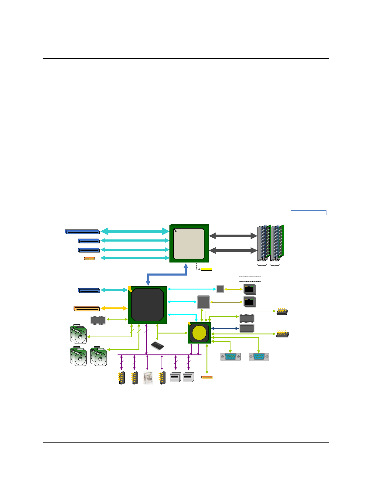
3. Functional Architecture
The architecture and design of the Intel® Server Board S1200BT is based on the Intel
®
C200
Chipset. The chipset is designed for systems based on the Intel® Xeon® processor in the FCLGA 1155 socket package.
The Intel® Server Board S1200BTL/S1200BTLRM use Intel® C204 Chipset and the Intel® Server
Board S1200BTS uses Intel® C202 Chipset.
The Intel® Xeon® Processor E3-1200 Processors are made up of multi-core processors based
on the 32nm processor technology. The Intel® Xeon® Processor E3-1200 V2 Processors are
made up of multi-core processors based on the 22nm processor technology. The 2nd Generation
Intel® Core™ i3 Processors are made up of dual-core processors based on the 32nm processor
technology. The 3rd Generation Intel® Core™ i3 Processors are made up of dual-core
processors based on the 22nm processor technology.
This chapter provides a high-level description of the functionality associated with each chipset
component and the architectural blocks that make up the server board.
Revision 2.4 Intel order number G13326-007
Figure 11. Intel® Server Board S1200BTL/S1200BTLRM Functional Block Diagram

Functional Architecture Intel® Server Board S1200BT TPS
16
PCIe Gen2 x4
x4 DMI Gen2
12
FLASHFLASH
LPC
Dual GbE
Intel® C202
Ch A Ch B
DDR3 (Channel B)
PCIe X8
XDP
PCIe Gen1 x1
SPI
GLCI
USB 2.0
Slot 7
(PCIe Gen1 x1 in physical)
TPM
Header
4 Unbuffered
DIMMs
GbE
GbE
22
DDR3 (Channel A)
Lewisville
GbE
PHY
USB
(x16 connector)
6
SATA 3G
GbE
Hartwell
2
USB
TPM
MEM
VTT
MEM VRD 12.0
BIOS Flash
Misc
VR s
PCIe X8
Slot 6
Knoxvill
Socket H2
Intel® Xeon®
Processor
(x8 connector)
Slot 5
(x8 connector)
Slot 4
Intel® Server Board S1200BTS Block
Diagram
ATX – 9.6" x 9.6"
PCI
Internal USB
Header x2
Rear I/O USB
Ports x2
Type-A
Header
SERIAL 1
VIDEO
Rear I/O
VGA Port
Rear I/O
COM Port
SATA-II
0
1
4
5
2
3
A1 A0 B1 B0
VTT
VPLL
VSA
VRD 12.0
VCORE
SERIAL 2
Internal
Header
SM712
PCI 32/33
SIO
W83627DHGP
Figure 12. Intel® Server Board S1200BTS Functional Block Diagram
3.1 Processor Sub-System
The Intel® Server Board S1200BT supports the following processors:
The Intel® Xeon® E3-1200 Processors are made up of multi-core processors based on the 32nm
processor technology. The 2nd Generation Intel® Core™ i3 Processors are made up of dual-core
processors based on the 32nm processor technology.
The Intel® Server Board S1200BTR also supports the following processors:
The Intel® Xeon® E3-1200 V2 Processors are made up of multi-core processors based on the
22 nm processor technology. The 3rd Generation Intel® Core™ i3 Processors are made up of
dual-core processors based on the 22nm processor technology.
Intel order number G13326-007 Revision 2.4
Intel
The 2
Intel
The 3
®
Xeon® E3-1200 Processors.
nd
Generation Intel® Core™ i3 Processors.
®
Xeon® E3-1200 V2 Processors.
rd
Generation Intel® Core™ i3 Processors.

Intel® Server Board S1200BT TPS Functional Architecture
17
3.1.1 Intel
®
Xeon® Processor E3-1200 Processors and Intel® Xeon® E3-1200 V2
Processors
The Intel® Xeon® E3-1200 Processors highly integrated solution variant is composed of quad
processor cores.
FC-LGA 1155 socket package with five GT/s.
Up to 95 W Thermal Design Power (TDP); processors with higher TDP are not
supported.
The Intel® Xeon® E3-1200 V2 Processors highly integrated solution variant is composed of quad
processor cores.
FC-LGA 1155 socket package with five GT/s.
Up to 95 W Thermal Design Power (TDP); processors with higher TDP are not
supported.
The list of supported processors may be found at http://serverconfigurator.intel.com.
Note: The workstation processor is not supported in this platform.
3.1.2 The 2nd Generation Intel
®
Core™ i3 Processors and the 3rd Generation Intel®
Core™ i3 Processors
The 2nd Generation Intel® Core™ i3 Processors highly integrated solution variant is composed of
Dual cores.
FC-LGA 1155 socket package with five GT/s.
Up to 65 W Thermal Design Power (TDP); processors with higher TDP are not
supported.
The 3rd Generation Intel® Core™ i3 Processors highly integrated solution variant is composed of
Duo cores.
FC-LGA 1155 socket package with five GT/s.
Up to 65 W Thermal Design Power (TDP); processors with higher TDP are not
supported.
The list of supported processors may be found at http://serverconfigurator.intel.com.
3.1.3 Intel
®
Turbo Boost Technology
Intel® Turbo Boost Technology is featured on certain processors in the Intel® Xeon® Processor
1200 Series. Intel® Turbo Boost Technology opportunistically and automatically allows the
processor to run faster than the marked frequency if the processor is operating below power,
temperature, and current limits. This results in increased performance for both multi-threaded
and single-threaded workloads.
Intel® Turbo Boost Technology operation:
Operates under Operating System control – It is only entered when the operating system
requests the highest (P0) performance state.
Operation can be enabled or disabled in BIOS Setup.
Revision 2.4 Intel order number G13326-007

Functional Architecture Intel® Server Board S1200BT TPS
18
Converts any available power and thermal headroom into a higher frequency on active
cores.
At nominal marked processor frequency, many applications consume less than the rated
processor power draw.
Availability is independent of the number of active cores.
Maximum Turbo Boost frequency depends on the number of active cores and varies by
processor configuration.
The amount of time the system spends in Intel
®
Turbo Boost operation depends on
workload, operating environment, and platform design.
If the processor supports the Intel® Turbo Boost Technology feature, the BIOS Setup provides
an option to enable or disable this feature. The default state is “enabled”.
3.2 Memory Subsystem
The Intel® Xeon® Processor E3-1200 series or Intel® Core™ Processor i3 series have an
Integrated Memory Controller (IMC) in its package. Each processor produces up to two DDR3
channels of memory. Each DDR3 channel in the IMC supports up to two UDIMM slots. The
DDR3 UDIMM frequency can be 1066/1333 (for Intel® Xeon® E3-1200 Processors or the 2nd
Generation Intel® Core™ i3 Processors) and 1333/1600 (for Intel® Xeon® E3-1200 V2
Processors or the 3nd Generation Intel® Core™ i3 Processors) MHz. Only ECC memory is
supported on this platform.
The memory channels are named as “Channel A” and “Channel B”.
The memory slots are named as “Slot1” and “Slot2” on each channel. Slot1will be the
farthest from the processor socket.
DIMMs are named to reflect the channel and slot in which they are installed:
o Channel A, Slot1 is “DIMM_A1”.
o Channel A, Slot2 is “DIMM_A2”.
o Channel B, Slot1 is “DIMM_B1”.
o Channel B, Slot2 is “DIMM_B2”.
3.2.1 Memory Supported
The Intel® Server Board S1200BT family supports various DDR3 DIMM modules of different
types and sizes and speeds.
In this section, the statements of support are subject to qualification in two ways:
For S1200 Server Boards with an SNB-DT processor, the Server Board and the BIOS may
support:
DIMMs composed of Dynamic Random Access Memory (DRAM) chips using 1 Gb, 2 Gb,
or 4 Gb technology.
DIMMs using x8 DRAM technology only.
DIMMs organized as Single Rank (SR) or Dual Rank (DR).
DIMM sizes of 1 GB, 2 GB, 4 GB, or 8 GB.
For Intel® Xeon® E3-1200 Processors or the 2nd Generation Intel® Core™ i3 Processors,
the DIMM speeds of 1066 or 1333 MT/s (megatransfers/second).
Intel order number G13326-007 Revision 2.4
 Loading...