

Page 1

Intel® Desktop Boards
D845GRG and D845GBV
Quick Reference
This guide is written for technically qualified personnel with experience
installing and configuring desktop boards.
Before You Begin
Warning and Cautions......................................................................... 3
Safety and Regulatory Notice ............................................................. 3
Desktop Board Components ....................................................... 4
Supported Components................................................................. 5
Installation Steps
1 Installing the I/O Shield ................................................................ 6
2 Installing the Desktop Board......................................................... 7
3 Installing the Processor ................................................................. 7
4 Installing the Memory Modules .................................................... 8
5 Installing an AGP Card................................................................. 9
6 Connecting the Fans..................................................................... 10
7 Attaching the IDE Drives............................................................. 10
Using the BIOS Setup Program................................................. 11
Setting the BIOS Configuration Jumper Block................. 11
Items on the Intel® Express Installer CD-ROM
• Product warranty
• Intel Express Installer
• Intel
• Software utilities and drivers
• Software license agreement
• Readme file
Part Number: A84616-002
®
Desktop Boards D845GRG and D845GBV Product Guide
Page 2

Getting Help
View or download product support information from Intel’s World Wide
Web site:
http://support.intel.com/support/motherboards/desktop/
Follow the link to your Intel Desktop Board for the following information:
• Known Issues and Solutions
• Software and Drivers (latest BIOS and driver updates)
• Compatibility (supported Intel® processors and memory information)
• Product Documentation
Technical Product Specification
Specification Update
If you can’t find the information you need on the Web, contact your point of
purchase. The Intel World Wide Web site also includes telephone numbers and
billing charges, if applicable, for Intel customer support.
INFORMATION IN THIS DOCUMENT IS PROVIDED IN CONNECTION WITH
®
INTEL
PRODUCTS. NO LICENSE, EXPRESS OR IMPLIED, BY ESTOPPEL
OR OTHERWISE, TO ANY INTELLECTUAL PROPERTY RIGHTS IS GRANTED
BY THIS DOCUMENT. EXCEPT AS PROVIDED IN INTEL’S TERMS AND
CONDITIONS OF SALE FOR SUCH PRODUCTS, INTEL ASSUMES NO
LIABILITY WHATSOEVER, AND INTEL DISCLAIMS ANY EXPRESS OR
IMPLIED WARRANTY, RELATING TO SALE AND/OR USE OF INTEL
PRODUCTS INCLUDING LIABILITY OR WARRANTIES RELATING TO
FITNESS FOR A PARTICULAR PURPOSE, MERCHANTABILITY, OR
INFRINGEMENT OF ANY PATENT, COPYRIGHT OR OTHER INTELLECTUAL
PROPERTY RIGHT. INTEL PRODUCTS ARE NOT INTENDED FOR USE IN
MEDICAL, LIFE SAVING, OR LIFE SUSTAINING APPLICATIONS. INTEL MAY
MAKE CHANGES TO SPECIFICATIONS AND PRODUCT DESCRIPTIONS AT
ANY TIME, WITHOUT NOTICE.
The Desktop Boards D845GRG and D845GBV may contain design defects or
errors known as errata which may cause the product to deviate from published
specifications. Current characterized errata are available on request.
Contact your local Intel sales office or your distributor to obtain the latest
specifications and before placing your product order.
Copies of documents which have an ordering number and are referenced in this
document, or other Intel literature, may be obtained from Intel Corporation by
going to the World Wide Web site at: http://www.intel.com or by calling
1-800-548-4725.
Intel and Pentium are registered trademarks of Intel Corporation or its
subsidiaries in the United States and other countries.
†
Other names and brands may be claimed as the property of others.
Copyright © 2002, Intel Corporation
2 Intel Desktop Boards D845GRG and D845GBV
Quick Reference
Page 3

Before You Begin
Warning and Cautions
WARNING
Disconnect the board’s power supply from its AC power source
before you connect or disconnect cables, or install or remove any
board components. Failure to do this can result in personal injury or
equipment damage. Some circuitry on the desktop board can
continue to operate even though the front panel power switch is off.
CAUTION
Electrostatic discharge (ESD) can damage desktop board components.
Install the board at an ESD-controlled workstation. If such a workstation
is not available, wear an antistatic wrist strap or touch the surface of the
antistatic package before handling the board.
CAUTION
Many of the midboard and front panel connectors provide operating
voltage (+5 V DC and +12 V DC, for example) to devices inside the
computer chassis, such as fans and internal peripherals. These
connectors are not overcurrent protected. Do not use these connectors
for powering devices external to the computer chassis. A fault in the load
presented by the external devices could cause damage to the computer,
the interconnecting cables, and the external devices themselves.
Safety and Regulatory Notice
See the Intel Desktop Boards D845GRG and D845GBV Product Guide for all
applicable regulatory compliance statements, product certification markings, and
safety and electromagnetic compatibility (EMC) standards and regulations these
desktop boards are compliant with.
Replacement battery warning label provided: Place the label inside the chassis
in an easy-to-see location near the battery but not on the board itself.
Intended uses: This product was evaluated as information technology
equipment (ITE) for home or office use when installed into an appropriate
computer chassis. Other end uses or locations may require further evaluation.
Intel Desktop Boards D845GRG and D845GBV 3
Quick Reference
Page 4
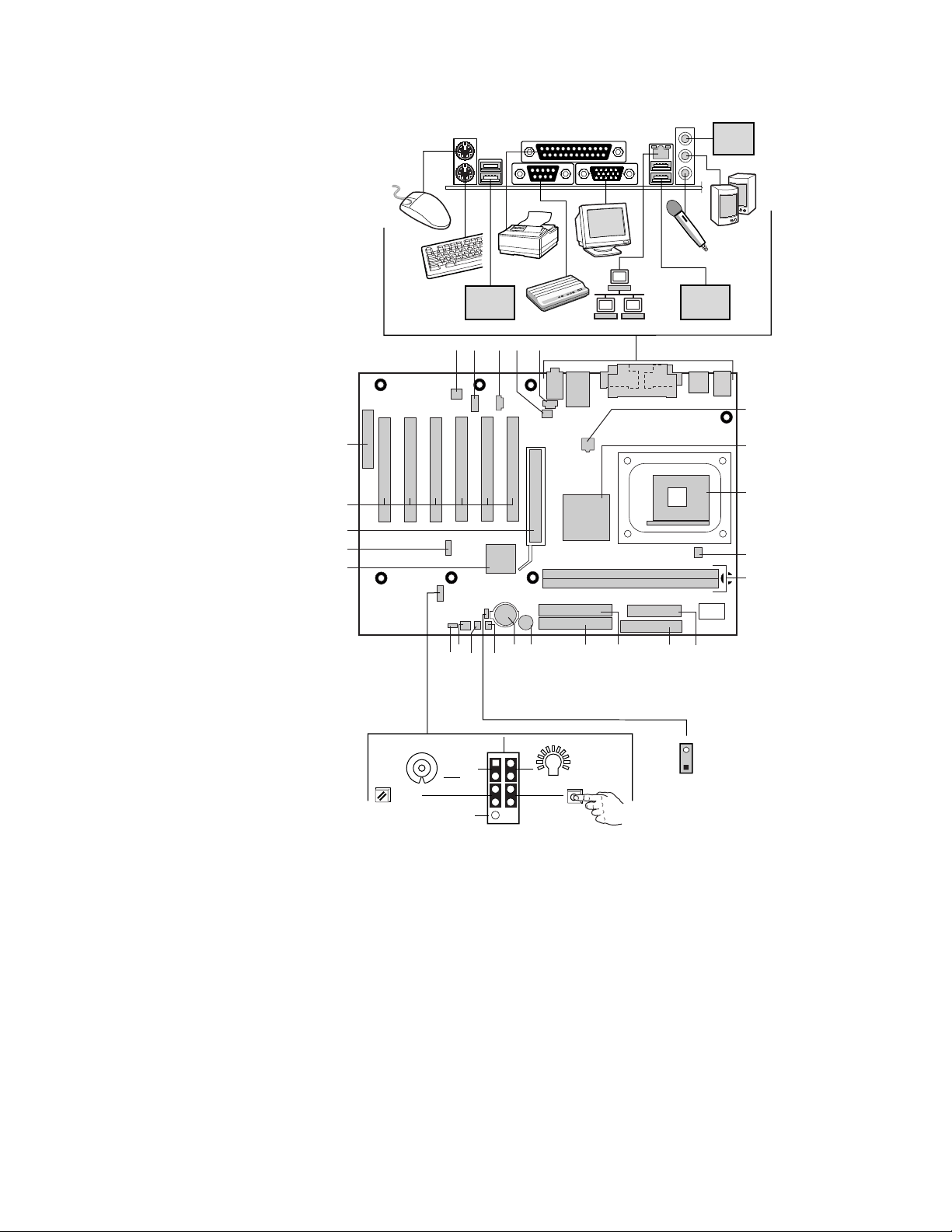
Desktop Board Components
Line
In
USB 2.0
Devices
A
USB 2.0
Devices
B C
D E
F
Y
G
H
X
W
V
U
Reset
No Connection
S
T
R
HD LED
Q
1
O
P
2
Power LED
On
M
N
K
L
3
1
2-pin alternate
power/sleep LED
connector
I
J
OM13885
4 Intel Desktop Boards D845GRG and D845GBV
Quick Reference
Page 5

Desktop Board Components (continued)
A Analog Devices Inc. AD1981A codec N Primary IDE connector
B Front panel audio connector O Speaker
C Auxiliary line-in connector (ATAPI) P Battery
D Rear chassis fan connector
(tach input)
E CD-ROM connector (ATAPI) R Chassis intrusion connector
F 12 V processor core voltage
connector
®
G Intel
Graphics and Memory
Controller Hub (GMCH)
H Processor socket U Intel
I Processor fan connector V Front panel USB 2.0 connector
J DIMM sockets W AGP connector
K Power connector X PCI bus add-in card connectors
L Diskette drive connector Y Communication and Networking
M Secondary IDE connector
CAUTION
Failure to use an ATX12V power supply, or not connecting the additional
power supply lead to the Desktop Board D845GRG or D845GBV may
result in damage to the desktop board and/or power supply.
For more information on the ATX12V power supply, refer to the Intel
Desktop Boards D845GRG and D845GBV Product Guide on the Intel
Express Installer CD-ROM.
Q SCSI hard drive activity LED
connector
S Front chassis fan connector
T BIOS configuration jumper block
®
82801DB I/O Controller
Hub (ICH4)
Riser (CNR) (optional)
NOTE
✏
The number of PCI slots on your board may differ from those in the
illustration.
Supported Components
Processors
The board supports the following processors:
Type
Intel® Pentium® 4 processor on
.13 micron process in an mPGA478
package
Intel Pentium 4 processor on
.13 micron process in an mPGA478
package
Intel Pentium 4 processor on
.18 micron process in an mPGA478
package
Intel Desktop Boards D845GRG and D845GBV 5
Quick Reference
Designation
2.40 and 2.26 GHz 533 MHz 512 KB
2.20, 2A, 1.80A,
and 1.60A GHz
2, 1.90, 1.80, 1.70,
1.60, and 1.50 GHz
Front Side Bus
Frequency
400 MHz 512 KB
400 MHz 256 KB
L2 Cache
Page 6

For the latest information on processors supported by Desktop Boards
D845GRG and D845GBV, refer to the Intel World Wide Web site at:
http://support.intel.com/support/motherboards/desktop
Memory Module Requirements
The desktop boards supports system memory as defined below:
• Up to two 184-pin Double Data Rate (DDR) 200/266 SDRAM Dual Inline
Memory Modules (DIMMs) with gold-plated contacts
• Unbuffered and non-registered single or double-sided DIMMs
• Serial Presence Detect (SPD) memory only
• Non-ECC and ECC DIMMs
• 2.5 V memory
NOTES
✏
The Desktop Boards D845GRG and D845GBV have been designed to
support DIMMs based on 512 Mbit technology up to 2 GB, but this
technology has not been validated on these boards.
All memory components and DIMMs used with the desktop boards must
comply with the PC SDRAM specifications. These include the PC
SDRAM Specification (memory component specific), the PC Unbuffered
DIMM Specification. To view or download these specifications, refer to
this Intel World Wide Web site:
http://www.intel.com/technology/memory/pcsdram/
For information about vendors that support these memory requirements,
refer to the Desktop Boards D845GRG and D845GBV link on this Intel
World Wide Web site:
http://support.intel.com/support/motherboards/desktop/
Installation Steps
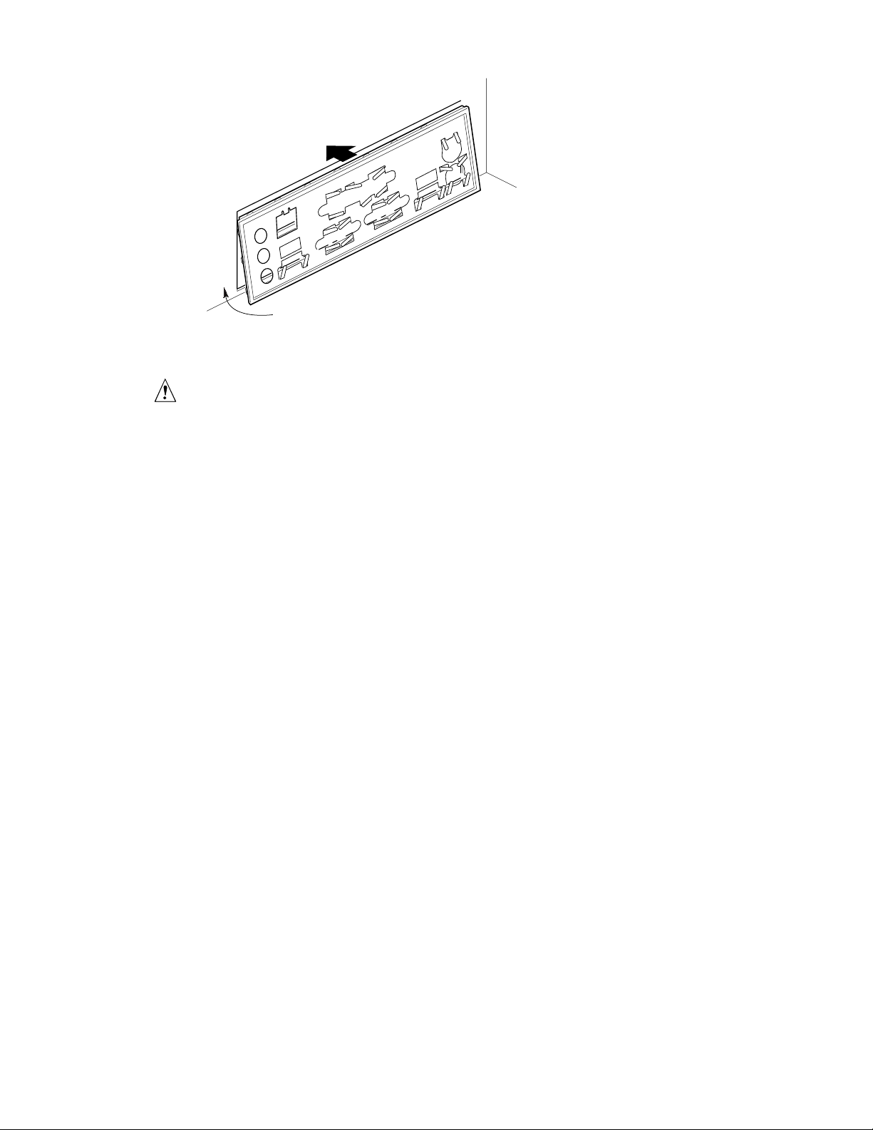
1 Installing the I/O Shield
The board comes with an I/O shield. When installed in the chassis, the shield
blocks radio frequency transmissions, necessary to pass emissions (EMI)
certification testing, protects internal components from dust and foreign objects,
and promotes correct airflow within the chassis.
Install the I/O shield before installing the board in the chassis. Place the shield
inside the chassis as shown in the following figure. Press the shield into place so
that it fits tightly and securely. If the shield doesn’t fit, obtain a properly sized
shield from the chassis supplier.
6 Intel Desktop Boards D845GRG and D845GBV
Quick Reference
Page 7
OM12116
2 Installing the Desktop Board
CAUTION
Failure to use an ATX12V power supply, or not connecting the additional
power supply lead to the Desktop Boards D845GRG and D845GBV may
result in damage to the desktop board and/or power supply.
For more information on the ATX12V power supply, refer to the Intel
Desktop Boards D845GRG and D845GBV Product Guide on the Intel
Express Installer CD-ROM.
Refer to your chassis manual for specific instructions on installing and removing
the desktop board.
Secure the desktop board to the chassis standoffs using the screws. The Desktop
Board D845GRG is secured to the chassis with six and Desktop Board
D845GBV with eight screws. Refer to the board illustration on page 4 for the
location of the mounting holes.
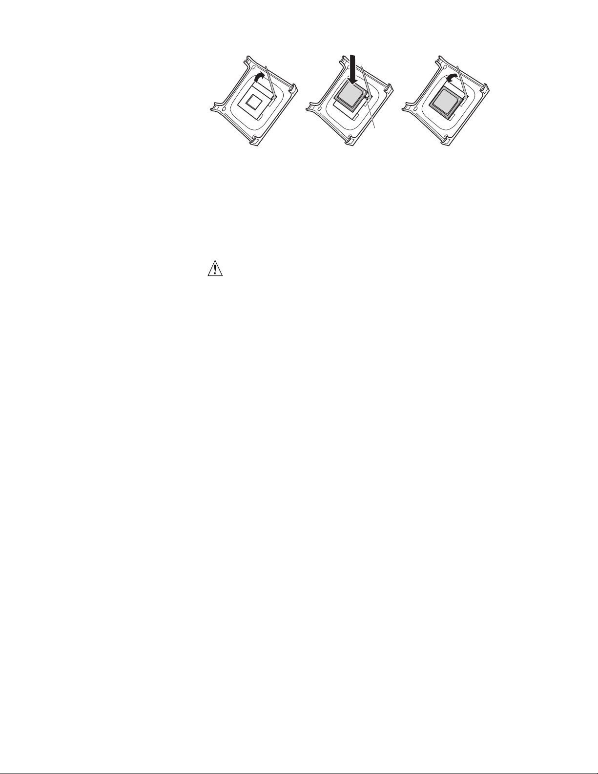
3 Installing the Processor
To install the processor, follow these steps
1. Observe the precautions in “Before You Begin” on page 3.
2. Lift the processor socket lever.
3. Install the processor so that the corner with the triangle marking (A) is
aligned with the corner where the lever is attached to the socket.
4. Lower the lever back to its original position.
Intel Desktop Boards D845GRG and D845GBV 7
Quick Reference
Page 8
mPGA478B
mPGA478B
mPGA478B
A
OM12078
5. The desktop boards have an integrated processor fan heat sink retention
mechanism (RM). For instructions on how to install the processor fan heat
sink, refer to the boxed processor manual or the Intel World Wide Web
site at:
http://support.intel.com/support/processors/pentium4/intnotes478.htm
4 Installing the Memory Modules
CAUTION
Install memory in the DIMM sockets prior to installing the AGP video card
to avoid interference with the memory retention mechanism.
The Desktop Boards D845GRG and D845GBV’s two DIMM sockets are
arranged as Banks 0 and 1, as shown in the following figure. If installing a
single DIMM, install it in Bank 0.
To install DIMMs, follow these steps:
1. Remove the AGP video card if it interferes with the DIMM clips from
being easily opened and closed.
2. Align the small notch in the bottom edge of the DIMM with the key in the
socket.
3. Insert the bottom edge of the DIMM into the socket.
4. When the DIMM is inserted, push down on the top edge of the DIMM until
the retaining slips snap into place. Make sure the clips are firmly in place.
8 Intel Desktop Boards D845GRG and D845GBV
Quick Reference
Page 9

0
1
OM13600
5 Installing an AGP Card
✏ NOTE
The D845GRG and D845GBV boards are only compatible with 1.5 V AGP
cards.
The Desktop Boards D845GRG and D845GBV have an integrated AGP card
retention mechanism (RM). Follow these instructions to install an AGP card:
1. Place the AGP card in the AGP connector.
2. Press down on the card until it is completely seated in the connector and the
card retention notch snaps into place below the RM.
3. Secure the card’s metal bracket to the chassis back panel with a screw.
To remove the AGP card, push back on the RM lever (A) until the retention pin
completely clears the notch in the card.
A
OM13851
Intel Desktop Boards D845GRG and D845GBV 9
Quick Reference
Page 10

6 Connecting the Fans
The following figure shows the location of the fan connectors. Connect the
processor’s fan heatsink cable to the processor fan connector on the board.
Connect the chassis fan cables to the board connectors as shown in the following
figure.
Chassis Rear
3
J6B2
Fan
Chassis Front
Fan
1
1
Processor
Fan
1
3
J2F1
3
J9H3
OM13699
7 Attaching the IDE Drives
The Intel® boxed desktop board package includes two IDE cables. Either cable
can connect two drives to the desktop board. The cables support the Ultra
DMA-33 (40-contact, 40-conductor) or ATA-66/100 (40-contact, 80-conductor)
transfer protocols and are backward compatible with drives using slower IDE
transfer protocols.
The cable will work correctly only when oriented as shown in the following
figure. For correct cable function:
1. Observe the precautions in “Before You Begin” on page 3.
2. Attach the cable end with the single connector (A) to the board.
3. Attach the cable end with the two closely spaced connectors (B) to the
drives.
10 Intel Desktop Boards D845GRG and D845GBV
Quick Reference
Page 11

3
1
J9H2
A
B
OM13887
Using the BIOS Setup Program
The BIOS Setup program can be used to view and change the BIOS settings for
the computer. The BIOS Setup program is accessed by pressing the <F2> key
after the Power-On Self-Test (POST) memory test begins and before the
operating system boot begins.
Setting the BIOS Configuration Jumper Block
CAUTION
Always turn off the power and unplug the power cord from the computer
before changing the jumper block settings. Moving the jumper with the
power on may result in unreliable computer operation.
The BIOS configuration jumper block determines the operating mode of the
BIOS Setup Program and enables BIOS recovery in the event of a failed
BIOS update (see the previous illustration for the location of the jumper block).
Intel Desktop Boards D845GRG and D845GBV 11
Quick Reference
Page 12

The following table describes the jumper block settings for the BIOS Setup
configuration jumper.
BIOS Setup Configuration Jumper Block (J9H2) Settings
Jumper Setting Mode Description
3
1
3
1
3
1
*To update or recover the BIOS, see the instructions in the Intel Desktop Boards D845EPT2
and D845EBG2 Product Guide on the Intel Express Installer CD-ROM
For a complete list of BIOS Setup settings, see:
• The Intel Dekstop Boards D845GRG and D845GBV Product Guide on the
Intel Express Installer CD-ROM
• The Intel World Wide Web Site at
http://support.intel.com/support/motherboards/desktop/
Normal (default)
(1-2)
Configure
(2-3)
Recovery
(None)
The BIOS uses the current configuration and
passwords for booting.
After the Power-On Self-Test (POST) runs, the
BIOS displays the Maintenance Menu. Use this
menu to clear passwords.
The BIOS recovers data from a recovery
diskette in the event of a failed BIOS update.*
.
12 Intel Desktop Boards D845GRG and D845GBV
Quick Reference
Page 13

Intel®
D845GRG
D845GBV
........................................................................................... 3
........................................................................................... 3
...................................................................................................... 4
........................................................................................................... 5
1 I/O ..................................................................................... 6
2
3
4
5
6
7
AGP ............................................................................................ 9
IDE ...................................................................................10
BIOS Setup ...............................................................11
BIOS .................................................................................11
®
Intel
Express Installer Intel
•
• Intel
• Intel
•
•
•
®
D845GRG D845GBV
......................................................................................... 7
............................................................................................. 7
......................................................................................... 8
...............................................................................................10
Page 14

Intel
http://support.intel.com/support/motherboards/desktop/
Intel
•
•
•
•
BIOS
Intel®
Intel
Intel
INTEL®
INTEL
INTEL INTEL
INTEL
INTEL INTEL
D845GRG
Intel Corporation
1-800-548-4725
Intel
†
Copyright © 2002, Intel Corporation
2 Intel D845GRG D845GBV
D845GBV
Intel
Intel
Pentium Intel Corporation
http://www.intel.com
Page 15

(ESD) ESD
+5 V +12 V
(EMC)
Intel D845GRG D845GBV
(ITE)
Intel D845GRG D845GBV 3
Page 16

Line
In
USB 2.0
Devices
A
USB 2.0
Devices
B C
D E
F
Y
G
H
X
W
V
U
Reset
No Connection
S
T
R
HD LED
Q
1
O
P
2
Power LED
On
M
N
K
L
3
1
2-pin alternate
power/sleep LED
connector
I
J
OM13885
4 Intel D845GRG D845GBV
Page 17

AAnalog Devices Inc. AD1981A
B
C
D
E
CD-ROM (ATAPI) R
12 V S
F
Intel®
G
(GMCH)
H
I
J
DIMM W AGP
K
L
M
IDE
(ATAPI) P
ATX12V D845GRG D845GBV
ATX12V Intel Express Installer Intel
Intel D845GRG D845GBV
IDE
N
O
Q SCSI
T BIOS
U Intel
V
X PCI
Y
LED
®
82801DB I/O
USB 2.0
(ICH4)
(CNR)
✏
PCI
Intel® Pentium® 4
.13
Intel Pentium 4
.13
Intel Pentium 4
.18
mPGA478
mPGA478
mPGA478
2.40
2.26 GHz 533 MHz 512 KB
2.20, 2A, 1.80A
1.60A GHz
2, 1.90, 1.80, 1.70,
1.60
1.50 GHz
D845GRG D845GBV
Intel
http://support.intel.com/support/motherboards/desktop
Intel D845GRG D845GBV 5
400 MHz 512 KB
400 MHz 256 KB
Page 18

• 184 (DDR)
200/266 SDRAM (DIMM)
•
•
ECC ECC DIMM
•
• 2.5 V
DIMM
(SPD)
✏
D845GRG D845GBV 512 Mbit
DIMM
PC SDRAM PC DIMM
http://www.intel.com/technology/memory/pcsdram/
D845GRG D845GBV
http://support.intel.com/support/motherboards/desktop/
1 I/O
I/O
I/O
2 GB
DIMM PC SDRAM
Intel
Intel
(EMI)
6 Intel D845GRG D845GBV
Page 19

2
ATX12V D845GRG D845GBV
ATX12V Intel Express Installer Intel
OM12116
Intel D845GRG D845GBV
D845GRG
6 D845GBV 8
4
3
1.
2.
3.
(A)
4.
Intel D845GRG D845GBV 7
3
Page 20

m
P
G
A
4
7
8
B
m
P
G
A
4
7
8
B
m
P
G
A
4
7
8
B
A
OM12078
5.
(RM)
Intel
http://support.intel.com/support/processors/pentium4/intnotes478.htm
4
AGP DIMM
D845GRG D845GBV DIMM
Banks 0 Bank 1 DIMM
Bank 0
DIMM
1.
DIMM
2.
DIMM
3.
4.
DIMM DIMM
DIMM AGP
8 Intel D845GRG D845GBV
Page 21

5 AGP
✏
D845GRG D845GBV 1.5 V AGP
D845GRG D845GBV AGP
(RM)
1.
2. AGP
3.
AGP
AGP AGP
AGP (A)
OM13600
0
1
A
OM13851
Intel D845GRG D845GBV 9
Page 22

6
Chassis Rear
Fan
Chassis Front
1
3
J6B2
Processor
Fan
1
3
J2F1
Fan
3
1
J9H3
OM13699
7 IDE
®
Intel
40 40 Ultra DMA-33 40
80 ATA-66/100
IDE
1. 3
2.
3.
IDE
(A)
(B)
10 Intel D845GRG D845GBV
Page 23

3
1
J9H2
A
B
OM13887
BIOS Setup
BIOS Setup BIOS
(POST) <F2>
BIOS Setup
BIOS
BIOS BIOS Setup
BIOS
BIOS
Intel D845GRG D845GBV 11
Page 24

BIOS Setup
BIOS Setup (J9H2)
* BIOS Intel Express Installer Intel
3
1
3
1
3
1
Intel D845GRG D845GBV
(1-2)
(2-3)
BIOS
Maintenance
(POST) BIOS
BIOS BIOS
BIOS *
BIOS Setup
• Intel Express Installer
Intel
Intel D845GRG D845GBV
•
Intel
http://support.intel.com/support/motherboards/desktop/
12 Intel D845GRG D845GBV
 Loading...