

Page 1

Intel® 810A3 Chipset Platform
Design Guide
July 2000
Order Number: 298186-002
Page 2

Information in this document is provided in connection with Intel products. No license, express or implied, by estoppel or otherwise, to any intellectual
property rights is granted by this document. Except as provided in Intel's Terms and Conditions of Sale for such products, Intel assumes no liability
whatsoever, and Intel disclaims any express or implied warranty, relating to sale and/or use of Intel products including liability or warranties relating to
fitness for a particular purpose, merchantability, or infringement of any patent, copyright or other intellectual property right. Intel products are not
intended for use in med ical, life saving, or life sustaini ng applications.
Intel may make changes to specifications and product descriptions at any time, without notice.
Contact your local Intel sales office or your distributor to obtain the latest specifications and before placing your product order.
®
The Intel
Current characterized errata are available on request.
I
Implementations of the I
810A3 Chipset may contain design defects or errors known as errata which may cause the product to deviate from published specifications.
2
C is a two-wire communications bus/protocol developed by Philips. SMBus is a subset of the I2C bus/protocol and was developed by Intel.
2
C bus/protocol or the SMBus bus/protocol may require licenses from various entities, including Philips Electronics N.V. and
North American Philips Corporation.
Copies of documents which have an ordering number and are referenced in this document, or other Intel literature may be obtained by:
calling 1-800-548-4725 or
by visiting Intel's website at http://www.intel.com.
Copyright © Intel Corporation, 2000
*Third-party brands and names are the property of their respective owners.
Intel® 810A3 Chipset Design Guide
Page 3

Contents
1 Introduction................................................................................................................1-1
1.1 About This Design Guide..............................................................................1-1
1.1.1 Terminology and Definitions ...................................... ...... ....... ...... ...1-2
1.1.2 References.......................................................................................1-7
1.2 System Overview..........................................................................................1-7
1.2.1 Graphics and Memory Controll er Hub (GMCH) ............................ ...1-8
1.2.2 I/O Controller Hub (82801AA ICH)...................................................1-9
1.2.3 System Configurations.....................................................................1-9
1.3 Platform Initiatives.......................................................................................1-10
1.3.1 Hub Interface .................................................................................1-10
1.3.2 Manageability.................................................................................1-10
1.3.3 AC’97.............................................................................................1-11
1.3.4 Low Pin Count (LPC) Interface......................................................1-12
2 PGA370 Processor Design Guidelines......................................................................2-1
2.1 Electrical Differences for Flexible PGA370 Designs.....................................2-1
2.2 PGA370 Socket Definition Details ................................................................2-2
2.2.1 Processor Pin Definition Comparison ..............................................2-3
2.2.2 Layout Guidelines for Intel
2.2.3 Undershoot/Overshoot Requirements .............................................2-9
2.2.4 BSEL[1:0] Implementation for PGA370 Designs .............................2-9
2.2.5 CLKREF Circuit Implementation....................................................2-10
2.2.6 Undershoot/Overshoot Requirements ...........................................2-10
2.2.7 Connecting RESET# and RESET2# on a Flexible
PGA370 Design .............................................................................2-11
2.2.8 Reset Strapping Options................................................................2-11
2.2.9 Voltage Regulation Differences .....................................................2-12
2.2.10 Decoupling Guidelines for Flexible PGA370 Designs....................2-12
2.2.11 Thermal/EMI Differences ...............................................................2-13
2.2.12 Debug Port Changes .....................................................................2-14
®
Pentium® III Processors......................2-4
3 SC242 Processor Design Guidelines.........................................................................3-1
3.1 Intel
3.2 Determine General Topology and Layout.....................................................3-3
3.3 Solution Space..............................................................................................3-3
3.4 Minimizing Crosstalk.....................................................................................3-4
3.5 Motherboard Layout Rules for Non-AGTL+ (CMOS) Signals.......................3-4
3.6 THRMDP and THRMDN........................ ....... ...... ....... ...... ....... ...... ....... ...... ...3-5
3.7 Additional Considerations.............................................................................3-5
3.8 Motherboard Frequency Select for SC242 Designs .....................................3-6
3.9 S.E.C.C. 2 Grounding Retention Mechanism (GRM)....................................3-7
4 Layout and Routing Guidelines..................................................................................4-1
4.1 General Recommendations ............. ...... ....... ...... ..........................................4-1
4.2 Nominal Board Stackup................................................................................4-1
4.3 Component Quadrant Layouts......................................................................4-2
4.4 Intel
Intel® 810A3 Chipset Design Guide iii
®
Pentium® III Processors Layout Guidelines........................................3-1
3.9.1 Motherboard Interfaces....................................................................3-7
®
810A3 Chipset Component Placement...............................................4-4
Page 4

4.5 System Memory Layout Guidelines..............................................................4-5
4.5.1 System Memory Solution Space......................................................4-5
4.5.2 System Memory Routing Example...................................................4-6
4.5.3 System Memory Connectivity ..........................................................4-7
4.6 Display Cache Interface................................................................................4-7
4.6.1 Display Cache Solution Space .............................. ....... ...... ....... ......4-8
4.7 Hub Interface ................................................................................................4-9
4.7.1 Data Signals ............................................. ....... ...... ....... ...... ....... ....4-10
4.7.2 Strobe Signals ...............................................................................4-10
4.7.3 HREF Generation/Distribution .......................................................4-10
4.7.4 Compensation................................................................................4-11
4.8 Ultra ATA/66 ...............................................................................................4-12
4.8.1 IDE Routing Guidelines .................................................................4-12
4.8.2 Ultra ATA/66 Detection..................................................................4-15
4.9 AC’97..........................................................................................................4-18
4.9.1 Audio/Modem Riser Card (AMR)...................................................4-18
4.9.2 AC’97 Routing................................................................................4-19
4.9.3 Motherboard Implementation.........................................................4-21
4.10 USB ............................................................................................................4-22
4.11 IOAPIC (I/O Advanced Programmable Interrupt Controller).......................4-23
4.12 PCI..............................................................................................................4-24
4.13 RTC ............................................................................................................4-24
4.13.1 RTC Crystal ...................................................................................4-24
4.13.2 External Capacitors .......................................................................4-25
4.13.3 RTC Layout Considerations...........................................................4-26
4.13.4 RTC External Battery Connection..................................................4-26
4.13.5 RTC External RTCRESET Circuit..................................................4-27
4.13.6 VBIAS DC Voltage and Noise Measurements..............................4-27
4.14 Processor PLL Filter Recommendation......................................................4-28
4.14.1 Processor PLL Filter Recommendation .........................................4-28
4.14.2 Topology........................................................................................4-28
4.14.3 Filter Specification .........................................................................4-28
4.14.4 Recommendation for Intel Platforms..............................................4-30
4.14.5 Custom Solutions................................ ...... ....... ..............................4-31
4.15 RAMDAC/Display Interface ........................................................................4-32
4.15.1 Reference Resistor (Rset) Calculation...........................................4-33
4.15.2 RAMDAC Board Design Guidelines...............................................4-33
4.16 DPLL Filter Design Guidelines....................................................................4-35
4.16.1 Filter Specification .........................................................................4-36
4.16.2 Recommended Routing/Component Placement............................4-37
4.16.3 Example LC Filter Components.....................................................4-37
5 Advanced System Bus Design ..................................................................................5-1
5.1 AGTL+ Design Guidelines............................................................................5-1
5.1.1 Initial Timing Analysis......................................................................5-2
5.1.2 Determine General Topology, Layout, and Routing Desired...........5-3
5.1.3 Pre-Layout Simulation .....................................................................5-3
5.1.4 Place and Route Board....................................................................5-5
5.1.5 Post-Layout Simulation....................................................................5-7
5.1.6 Validation.........................................................................................5-8
5.2 Theory.........................................................................................................5-10
5.2.1 AGTL+ ...........................................................................................5-10
iv Intel® 810A3 Chipset Design Guide
Page 5

5.2.2 Timing Requirements.....................................................................5-10
5.2.3 Cross-Talk Theory .........................................................................5-11
5.3 More Details and Insight.............................................................................5-13
5.3.1 Textbook Timing Equations ...........................................................5-13
5.3.2 Effective Impedance and Tolerance/Variation ...............................5-14
5.3.3 Power/Reference Planes, PCB Stackup, and High
Frequency Decoupling...................................................................5-14
5.3.4 Clock Routing......... ....... ...... ...........................................................5 -1 7
5.4 Definitions of Flight Time Measurements/Corrections and Signal Quality..5-18
5.4.1 V
Guardband............................................................................5-18
REF
5.4.2 Ringback Levels.............................................................................5-18
5.4.3 Overdrive Region...........................................................................5-18
5.4.4 Flight Time Definition and Measurement .......................................5-19
5.5 Conclusion ..................................................................................................5-19
6 Clocking.....................................................................................................................6-1
6.1 Clock Generation ............................. ...... ....... ...... ....... ...... ....... ...... ................6- 1
6.2 Clock Architecture......... ...... ....... ...... ...... ....... ...... ....... ...................................6-2
6.3 Clock Routing Guidelines .... ....... ...... ...... .......................................................6- 3
6.4 Capacitor Sites..............................................................................................6-6
6.5 Clock Power Decoupling Guideli nes................................ ....... ...... ....... ...... ...6-6
7 System Design Considerations..................................................................................7-1
7.1 Power Delivery..............................................................................................7-1
7.1.1 Intel
®
810A3 Chipset Power Delivery ..............................................7-1
7.1.2 LED Indicator for S0-S5 States........................................................7-5
7.2 Decoupling Guidelines..................................................................................7-6
7.2.1 Vcc
Decoupling........................................................................7-6
CORE
7.2.2 Phase Lock Loop (PLL) Decoupling ................................................7-6
7.2.3 82810A3 GMCH Decoupling Guidelines..........................................7-7
7.2.4 Ground Flood Planes........................................................................7-8
7.3 Thermal Design Power .................................................................................7-8
7.4 Power Sequencing........................................................................................7-9
8 Design Checklist ........................................................................................................8-1
8.1 Design Review Checklist ........................................................ ...... ....... ...... ...8-1
8.1.1 Design Checklist Summary........................... ...... ....... ...... ....... ...... ...8-1
8.2 Pullup and Pulldown Resistor Values .........................................................8-15
8.3 RTC.............................................................................................................8-16
8.4 Power Management Signals.......................................................................8-16
8.4.1 Power Button Implementation........................................................8-18
9 Third-Party Vendor Information..................................................................................9-1
A PCI Devices/Functions/Registers/Interrupts ............................................................. A-1
Intel® 810A3 Chipset Design Guide v
Page 6

Figures
1-1 Intel® 810A3 Chipset ....................................................................................1-9
1-2 AC'97 with Audio and Modem Codec Connections....................................1-12
2-1 Topology for 370-Pin Socket Designs with Single Ended
Termination (SET) ........................................................................................2-6
2-2 Routing for THRMDP and THRMDN ............................................................2-8
2-3 BSEL[1:0] Circuit Implementation for PGA370 Designs...............................2-9
2-4 Examples for CLKREF Divider Circuit ........................................................2-10
2-5 RESET# Schematic for PGA370 Designs ................................. ...... ....... ....2-11
2-6 Capacitor Placement on the Motherboard..................................................2-12
2-7 TAP Connector Comparison............................ ...... ....... ...... ....... ...... ....... ....2-14
3-1 Intel
3-2 Routing for THRMDP and THRMDN ............................................................3-5
3-3 System Bus Frequency Selection Topology for SC242................................3-6
3-4 Hole Locations and Keep-out Zones for Support Components ....................3-7
3-5 Detailed Drawing of Minimum Ground Pad Size and Location.....................3-8
4-1 Nominal Board Stackup................................................................................4-2
4-2 GMCH Quadrant Layout (topview) ...............................................................4-2
4-3 ICH 241-uBGA Quadrant Layout (topview) ..................................................4-3
4-4 uATX Placement Example for PGA370 Processors.....................................4-4
4-5 System Memory Topologies .........................................................................4-5
4-6 System Memory Routing Example ...............................................................4-6
4-7 System Memory Connectivity .......................................................................4-7
4-8 Display Cache (Topology 1) .........................................................................4-7
4-9 Display Cache (Topology 2) .........................................................................4-8
4-10 Display Cache (Topology 3) .........................................................................4-8
4-11 Display Cache (Topology 4) .........................................................................4-9
4-12 Hub Interface Signal Routing Example.........................................................4-9
4-13 Single Hub Interface Reference Divider Circuit..........................................4-11
4-14 Locally Generated Hub Interface Reference Dividers ................................4-11
4-15 IDE Min/Max Routing and Cable Lengths...................................................4-12
4-16 Ultra ATA/66 Cable.....................................................................................4-13
4-17 Resistor Schematic for Primary IDE Connectors........................................4-14
4-18 Resistor Schematic for Secondary IDE Connectors...................................4-14
4-19 Host-Side IDE Cable Detection ..................................................................4-16
4-20 Host-Side IDE Cable Detection ..................................................................4-17
4-21 Host-Side IDE Cable Detection ..................................................................4-17
4-22 Tee Topology AC'97 Trace Length Requirements for ATX ........................4-20
4-23 Daisy-Chain Topology AC'97 Trace Length Requirements for ATX...........4-20
4-24 USB Data Signals.......................................................................................4-23
4-25 PCI Bus Layout Example for 4 PCI Connectors.........................................4-24
4-26 External Circuitry for the ICH RTC..............................................................4-25
4-27 A Diode Circuit to Connect RTC External Battery ......................................4-26
4-28 RTCRESET External Circuit for the ICH RTC ............................................4-27
4-29 Filter Topology............................................................................................4-28
4-30 Filter Specification ......................................................................................4-29
4-31 Using Discrete R.........................................................................................4-30
4-32 No Discrete R .............................................................................................4-31
4-33 Core Reference Model................................................................................4-31
4-34 Schematic of RAMDAC Video Interface .....................................................4-32
®
Pentium® III Uni-Processor Configuration ..........................................3-3
vi Intel® 810A3 Chipset Design Guide
Page 7

4-35 RAMDAC Component and Routing Guidelines ..........................................4-34
4-36 Recommended RAMDAC Reference Resistor Placement and
Connections................................................................................................4-35
4-37 Recommended LC Filter Connection..........................................................4-36
4-38 Frequency Response (see Table 4-13).......................................................4-38
5-1 PICD[1,0] Uni-Processor Topology...............................................................5-7
5-2 Test Load vs. Actual System Load ...............................................................5-9
5-3 Aggressor and Victim Networks..................................................................5-11
5-4 Transmission Line Geometry: (A) Microstrip (B) Stripline...........................5-11
5-5 One Signal Layer and One Reference Plane..............................................5-15
5-6 Layer Switch with One Reference Plane ....................................................5-15
5-7 Layer Switch with Multiple Reference Planes (same type).........................5-15
5-8 Layer Switch with Multiple Reference Planes.............................................5-16
5-9 One Layer with Multiple Reference Planes.................................................5-16
5-10 Overdrive Region and V
5-11 Rising Edge Flight Time Measurement.......................................................5-19
6-1 Intel
®
810A3 Chipset Clock Architecture ......................................................6-2
Guardband.....................................................5-19
REF
6-2 Different Topologies for the Clock Routing Guidelines .................................6-5
6-3 Example of Capacitor Placement Near Clock Input Receiver.......................6-6
7-1 Intel
®
810A3 Chipset Power Delivery Architecture.......................................7-2
7-2 82810A3 GMCH Power Plane Decoupling ...................................................7-8
7-3 G3-S0 Transistion.........................................................................................7-9
7-4 S0-S3-S0 Transition....................................................................................7-10
7-5 S0-S5-S0 Transition....................................................................................7-11
8-1 Pullup Resistor Example.............................................................................8-15
8-2 PWRGOOD and PWROK Logic .................................................................8-17
Intel® 810A3 Chipset Design Guide vii
Page 8

Tables
2-1 Platform Pin Definition Comparison for Single Processor Designs ..............2-2
2-2 Processor Pin Definition Comparison...........................................................2-3
2-3 Intel
®
Pentium® III Processor and GMCH AGTL+ Parameters for
Example Calculations ................... ...... ..........................................................2-4
2-4 Example T
2-5 Example T
FLT_MIN
FLT_MIN
Calculations FOR 100 MHz Bus.....................................2-5
Calculations (Frequency Independent)...........................2-5
2-6 Segment Descriptions and Lengths for Figure 2-1.......................................2-6
2-7 Trace Width (Space Gu id eli nes)............................ .......................................2-6
2-8 Routing Guidelines for Non-AGTL+ Signals.................................................2-8
2-9 Example Resistor Values for CLKREF Divider Circuit (3.3V Source).........2-10
3-1 Intel
®
Pentium® III Processor and GMCH AGTL+ Parameters for
Example Calculations ................... ...... ..........................................................3-1
3-2 Example T
3-3 Example T
FLT_MAX
FLT_MIN
Calculations for 100 MHz Bus .......................................3-2
Calculations (Frequency Independent)...........................3-2
3-4 Segment Descriptions and Lengths for Figure 3-2 ......................................3-3
3-5 Trace Width: Spa ce Guid el ine s ........... ...... ....... ...... ....... ...... ..........................3-3
3-6 Routing Guidelines for Non-AGTL+ Signals.................................................3-4
4-1 System Memory Routing ..............................................................................4-5
4-2 Display Cache Routing (Topology 1)............................................................4-8
4-3 Display Cache Routing (Topology 2)............................................................4-8
4-4 Display Cache Routing (Topology 3)............................................................4-8
4-5 Display Cache Routing (Topology 4)............................................................4-9
4-6 AC’97 Configuration Combinations.............................................................4-18
4-7 Recommended USB Trace Characteristics................................................4-23
4-8 Inductor.......................................................................................................4-30
4-9 Capacitor ....................................................................................................4-30
4-10 Resistor.......................................................................................................4-30
4-11 DPLL LC Filter Component Example..........................................................4-37
4-12 Additional DPLL LC Filter Component Example.........................................4-38
4-13 Resistance Values for Frequency Response Curves (see Figure 4-38).....4-39
5-1 Trace Width Spa ce Guid elines..... ...................................... ....... ...... ....... ......5-6
5-2 Host Clock Routing.......................................................................................5-6
6-1 Intel
®
810A3 Chipset Clocks.........................................................................6-1
6-2 Group Skew and Jitter Limits at the Pins of the Clock Chip .........................6-3
6-3 Signal Group and Resistor............................................................................6-3
6-4 Layout Dimensions .......................................................................................6-4
7-1 Intel
7-2 Intel
®
810A3 Chipset Power Map.................................................................7-3
®
810A3 Chipset Voltage Regulator Specifications ...............................7-4
7-3 Power Sequencing Timing Definitions........................................................7-12
8-1 AGTL+ Connectivity Checklist for 370-Pin Socket Processors.....................8-2
8-2 CMOS Connectivity Checklist for 370-Pin Socket Processors .....................8-3
8-3 TAP Checklist for a 370-Pin Sock et Proc es sor ...........................................8-3
8-4 Miscellaneous Checklist for 370-Pin Socket Processors..............................8-4
8-5 AGTL+ Connectivity Checklist for SC242 Processors..................................8-5
8-6 CMOS Connectivity Checklist for SC242 Processors...................................8-6
8-7 TAP Checklist for SC242 Process or s................................. ....... ...... ....... ......8- 6
8-8 Miscellaneous Checklist for SC242 Processors ...........................................8-6
8-9 Special Consideration Checklist ...................................................................8-7
8-10 Clock Generator Checklist............................................................................8-7
viii Intel® 810A3 Chipset Design Guide
Page 9

8-11 ICH Checklist................................................................................................8-8
8-12 ICH Checklist................................................................................................8-9
8-13 GMCH Checklist .........................................................................................8-10
8-14 System Memory Checklist ..........................................................................8-10
8-15 Display Cache Checklist.............................................................................8-11
8-16 LPC Super I/O Checklist.............................................................................8-11
8-17 IDE Checklist ..............................................................................................8-11
8-18 Clock Generator Checklist............... ...... ....... ...... ....... ...... ...........................8-12
8-19 FWH Flash BIOS Checklist.........................................................................8-12
8-20 PCI Bus Checklist.......................................................................................8-12
8-21 USB / Keyboard / Mouse Checklist.............................................................8-13
8-22 AC’97 Checklist...........................................................................................8-13
8-23 Power Delivery Checklist............................................................................8-14
9-1 Super I/O... ....... ...... .................................................................................... ...9-1
9-2 Clock Generation ................ ..........................................................................9-1
9-3 Memory Vendors...........................................................................................9-1
9-4 Voltage Regulator Vendors...........................................................................9-1
9-5 Flat Panel......................................................................................................9-1
9-6 TV-Out ..........................................................................................................9-2
9-7 Software DVD ...............................................................................................9-2
9-8 AC’97 ............................................................................................................9-2
9-9 TMDS Transmitters.......................................................................................9-3
9-10 TV Encoders.................................................................................................9-3
9-11 Combo TMDS Transmitters/TV Encoders ....................................................9-3
9-12 LVDS Transmitter .........................................................................................9-3
A-1 PCI Devices and Functions.......................................................................... A-1
A-2 PCI Devices and Registers.......................................................................... A-1
A-3 PCI Devices and Interrupts.......................................................................... A-2
Intel® 810A3 Chipset Design Guide ix
Page 10
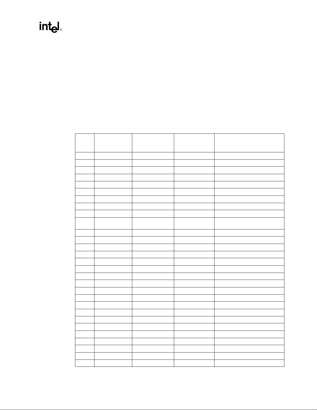
Revision History
Revision Description Date
001 Initial Release April 2000
002
• Minor edits throughout for clarity
• Added Section 7.2.4, Ground Flood Plane
July 2000
x Intel® 810A3 Chipset Design Guide
Page 11

Introduction
1
Page 12

This page is intentionally left blank
Page 13

Introduction
Introduction
This design guide provides motherboard design guidelines for Intel 810A3 chipset systems.
These design guidelines have been developed to ensure maximum flexibility for board designers
while reducing the risk of board related issues. In addition to design guidelines, this document
discusses Intel
The debug recommendations should be consulted when debugging an Intel
system; however, the debug recommendations should be understood before completing board
design to ensure that the debug port, in addition to other debug features, will be implemen ted
correctly.
•
Please note these earlier design guides are still current:
Intel
chipset device for Intel
Intel
82810E chipset device for the Intel
Bus designs.
1.1 About This Design Guide
This design guide is intended for hardware designers who are experienced with PC architectures
and board design. The design guide assumes that the designer has a working knowledge of the
vocabulary and practices of PC hardware design.
•
Chapter 1, “Introduction”—This chapter introduces the designer to the organization and
purpose of this design guide, and provides a list of references of related documents. This
chapter also provides an overview of the Intel
•
Chapter 2, “PGA370 Processor Design Guidelines”—This chapter provides design guidelines
for the PGA370 processor including processor-specific layout guidelines.
•
Chapter 3, “SC242 Processor Design Guidelines”—This chapter provides design guidelines
for the SC242 processor including processor-specific layout guidelines.
•
Chapter 4, “Layout and Routing Guidelines”—This chapter provides a detailed set of
motherboard layout and routing guidelines, except for processor-specific layout guidelines.
The motherboard functional units are covered (e.g., chipset component placement, system bus
routing, system memory layout, display cache interface, hub interface, IDE, AC’97, USB,
interrupts, SMBUS, PCD, LPC/FWH Flash BIOS, and RTC). For the PGA370 processor
specific layout guidelines, refer to Chapter 2, “PGA370 Processor Design Guidelines”. For the
SC242 processor spcific layout guidelines, refer to Chapter 3, “SC242 Processor Design
Guidelines”.
•
Chapter 5, “Advanced System Bus Design”—The goal of this chapter is to provide the system
designer with the information needed for the implementation of 133 MHz and 100 MHz
AGTL+ bus PCB layout.
•
Chapter 6, “Clocking”— This chapter provides motherboard clocking guidelines (e.g., clock
architecture, routing, capacitor sites, clock power decoupling, and clock skew).
•
Chapter 7, “System Design Con sider ations”— This chapter includes guidelines regarding
power deliver, decoupling, thermal, and power sequencing.
•
Chapter 8, “Design Checklist”— This chapter provides a design review checklist. ATA/66
detection, calculation of pullup/pulldown resistors, minimizing RTC ESD, and power
management signals are also discussed.
810A3 chipset system design issues (e.g., thermal requirements).
®
810 Chipset Design Guide, order number 290657, references the Intel
®
810E Chipset Platform Design Guide, order number 290675, references the Intel
®
Celeron™ processor 66 MHz Front Side Bus designs.
®
Pentium®
810A3 chipset
®
82810A2
processor 100 MHz / 133 MHz Front Side
III
®
810A3 chipset.
1
®
Intel®810A3 Chipset Design Guide 1-1
Page 14

Introduction
•
Chapter 9, “Third-Party Vendor Information”— This chapter includes information regarding
various third-party vendors who provide products to support the Intel
•
Appendix A, “PCI Devices/Functions/Registers/In ter rup ts”— This appendix lists the PCI
devices and functions supported by the Intel
component PCI Vendor ID, Device ID, Revision ID, Class code, Sub-class code, and
Programming Interface code values. In addition, component APIC interrupt and ISA/PCI
IRQs are listed.
1.1.1 Terminology and Definitions
Term Definition
Aggressor A network that transmits a coupled signal to another network is called
the aggressor network.
AGTL+
T
he processor system bus uses a bus technology called AGTL+, or
Assisted Gunning Transceiver Logic. AGTL+ buffers are open-drain
and require pull-up resistors for providing the high logic level and
termination. The processor AGTL+ output buffers differ from GTL+
buffers with the addition of an active pMOS pull-up transistor to “assist”
the pull-up resistors during the first clock of a low-to-high voltage
transition. Additionally, the processor Single Edge Connector (S.E.C.)
cartridge contains 56 Ω pull-up resistors to provide termination at each
bus load.
®
810A3 chipset.
®
810A3 chipset. Also included are a list of
Bus Agent A component or group of components that, when combined, represent a
single load on the AGTL+ bus.
Core power rail A power rail that is only on during
rails are on when the PSON signal is asserted to the ATX power supply.
The core power rails that are distributed
supply are: ±5V, ±12V and +3.3V.
Corner Describes how a component performs when all parameters that could
impact performance are adjusted to have the same impact on
performance. Examples of these parameters include variations in
manufacturing process, operating temperature, and operating voltage.
The results in performance of an electronic component that may change
as a result of corners include (but are not limited to): clock to output
time, output driver edge rate, output drive current, and input drive
current. Discussion of the “slow” corner would mean having a
component operating at its slowest, weakest drive strength performance.
Similar discussion of the “fast” corner would mean having a component
operating at its fastest, strongest drive strength performance. Operation
or simulation of a component at its slow corner and fast corner is
expected to bound the extremes between slowest, weakest performance
and fastest, strongest performance.
full-power
directly
operation. These power
from the ATX power
1-2
Intel®810A3 Chipset Design Guide
Page 15

Introduction
Term Definition
Cross-talk The reception on a victim network of a signal imposed by aggressor
network(s) through inductive and capacitive coupling between the
networks.
•
Backward Cross-talk - coupling which creates a signal in a victim
network that travels in the opposite direction as the aggressor’s
signal.
•
rward Cross-talk - coupling which creates a signal in a victim
Fo
network that travels in the same direction as the aggressor’s signal.
•
Even Mode Cross-talk - coupling from multiple aggressors when all
the aggressors switch in the same direction that the victim is
switching.
•
Odd Mode Cross-talk - coupling from multiple aggressors when all
the aggressors switch in the opposite direction that the victim is
switching.
Derived power rail A derived power rail is any power rail that is ge nerated from ano ther
power rail using an on-board voltage regulator. For example, 3.3VSB is
usually derived (on the motherboard) from 5VSB using a voltage
regulator.
Dual power rail A dual power rail is derived from different rails at different times
(depending on the power state of the system). Usually, a dual power rail
is derived from a standby supply during suspend operation and derived
from a core supply during full-power operation.
Edge Finger The cartridge electrical contact that interfaces to the SC242 connector.
Intel®810A3 Chipset Design Guide 1-3
Page 16

Introduction
Term Definition
Flight Time Flight Time is a term in the timing equation that includes the signal
propagation delay, any effects the system has on the T
of the driver,
CO
plus any adjustments to the signal at the receiver needed to gu arantee the
setup time of the receiver.
More precisely, flight time is defined to be:
•
The time difference between a signal at the input pin of a receiving
agent crossing V
(adjusted to meet the receiver manufacturer’s
REF
conditions required for AC timing specifications; i.e., ringback,
etc.), and the output pin of the driving agent crossing V
REF
if the
driver was driving the Test Load used to specify the driver’s AC
timings.
See Section for details regarding flight time simulation and
validation.
The V
Guardband takes into account sources of noise that may
REF
affect the way an AGTL+ signal becomes valid at the receiver. See
the definition of the V
•
Maximum and Minimum Flight Time - Flight time variations can
Guardband.
REF
be caused by many different parameters. The more obvious causes
include variation of the board dielectric constant, changes in load
condition, cross-talk, V
noise, V
TT
noise, variation in
REF
termination resistance and differences in I/O buffer performance as
a function of temperature, voltage and manufacturing process.
Some less obvious causes include effects of Simultaneous
Switching Output (SSO) and packaging effects.
•
The Maximum Flight Time is the largest flight time a network will
experience under all variations of condi ti ons . Maximu m fl ight time
is measured at the appropriate V
•
The Minimum Flight Time is the smallest flight time a network
Guardband boundary.
REF
will experience under all variations of conditions. Minimum flight
time is measured at the appropriate V
Guardband boundary.
REF
1-4
For more information on flight time and the V
Pentium
®
II Processor Developer’s Manual.
Guardband, see the
REF
Full-power operation During full-power operation, all components on the motherboard r emain
powered. Note that full-power operation includes both the full-on
operating state (S0) and the processor Stop Grant state (S1).
GTL+ GTL+ is the bus technology used by the Pentium Pro processor. This is
an incident wave switching, open-drain bus with pull-up resistors that
provide both the high logic level and termination. It is an enhancement
to the GTL (Gunning Transceiver Logic) technology. See the Pentium
®
II Processor Developer’s Manual for more details of GTL+.
Network The trace of a Printed Circuit Board (PCB) that completes an electrical
connection between two or more components.
Network Length The distance between extreme bus agents on the network and does not
include the distance connecting the end bus agents to the termination
resistors.
Intel®810A3 Chipset Design Guide
Page 17

Term Definition
Introduction
Overdrive Region Is the voltage range, at a receiver, located above and below V
signal integrity analysis. See the Pentium
®
II Processor Developer’s
REF
for
Manual for more details.
Overshoot Maximum voltage allowed for a signal at the processor core pad. See
each process’s Electrical, Mechanical, and Thermal Specification for
overshoot specificatio n.
Pad A feature of a semiconductor die contained within an internal logic
package on the S.E.C cartridge substrate used to connect the die to the
package bond wires. A pad is only observable in simulation.
Pin A feature of a logic package contained within the S.E.C. cartridge used
to connect the package to an internal substrate trace.
Power rails An ATX power supply has 6 power rails: +5V, -5V, +12V, -12V,
+3.3V, +5VSB. In addition to these power rails, several other power
rails can be created with voltage regulators.
Ringback Ringback is the voltage that a signal rings back to after achieving its
maximum absolute value. Ringback may be due to reflections, driver
oscillations, etc. See the respective Processor’s Electrical, Mechanical,
and Thermal Specification for ringback specification.
Settling Limit Defines the maximum amount of ringing at the receiving pin that a
signal must reach before its next transition. See the respective
Processor’s Electrical, Mechanical, and Thermal Specification for
settling limit specification.
Setup Window Is the time between the beginning of Setup to Clock (T
SU_MIN
) and the
arrival of a valid clock edge. This window may be different for each
type of bus agent in the system.
Simultaneous
Switching Output
(SSO) Effects
Refers to the difference in electrical timing parameters and degradation
in signal quality caused by multiple signal ou tputs simultaneously
switching voltage levels (e.g., high-to-low) in the opposite direction
from a single signal (e.g., low-to-high) or in the same direction (e.g.,
high-to-low). These are respectively called odd-mode switching and
even-mode switching. This simultaneous switching of multiple outputs
creates higher current swings that may cause additional propagation
delay (or “pushout”), or a decrease in propagation delay (or “pull-in”).
These SSO effects may impact the setup and/or hold times and are not
always taken into account by simulations. System timing budgets s hould
include margin for SSO effects.
Standby power rail A power rail that in on during suspend operation (these rails are also on
during full-power operation). These rails are on at all times (when the
power supply is plugged into AC power). The only standby power rail
that is distributed directly from the ATX power supply is 5VSB (5V
Standby). There can be other standby rails that are created with voltage
regulators.
Stub The branch from the trunk terminating at the pad of an agent.
Suspend operation During suspend operation, power i s remov ed from s ome compo nents on
the motherboard. The customer reference board supports three suspend
states: processor Stop Grant (S1), Suspend-to-RAM (S3) and Soft-off
(S5).
Intel®810A3 Chipset Design Guide 1-5
Page 18

Introduction
Term Definition
Suspend-To-RAM
(STR)
In the STR state, the system state is stored in main memory and all
unnecessary system logic is turned off. Only main memory and logic
required to wake the system remain powered.
Test Load Intel uses a 50 Ω test load for specifying its components.
Trunk The main connection, excluding interconnect branches, terminating at
agent pads.
Undershoot Maximum voltage allowed for a signal to extend below V
at the
SS
processor core pad. See the respective Processor’s Electrical,
Mechanical, and Thermal Specification for undershoot specifications.
Victim A network that receives a coupled cross-talk signal from another
network is called the victim network.
V
Guardband A guardband (DV
REF
realistic model accounting for noise such as cross-talk, V
noise.
V
REF
) defined above and below V
REF
to provide a more
REF
noise, and
TT
1-6
Intel®810A3 Chipset Design Guide
Page 19

1.1.2 References
•
Intel® 82810 Chipset: Intel® 82810/82810-DC 100 Graph ics and Memor y Con tr oller (GMCH)
Datasheet (Document Number: 290656)
•
Intel® 82801AA (ICH) and 82810AB (ICH0) I/O Controller Hub
(Document Number: 290655)
•
Intel® 82802AB/AC FirmWare Hub (FWH) Datasheet
•
Intel® Celeron Processor Data sh eet
•
Intel® Celeron Processor Specification Update
•
Intel® 810 Chipset Clock Synthesizer/Driver Specification
•
PPGA 370 Power Delivery Guidelines
•
Intel® Pentium® II Processor AGTL+ Guidelines
•
Intel® Pentium® II Processor Power Distribution Guidelines (
•
Intel® Pentium® II Processor Developer's Manual
•
Intel® Pentium II Processor at 350MHz, 400MHz and 450MHz Datasheet (Document
Number: 243657)
•
Intel® Pentium II Processor Specification Update (Document Number: 243337)
•
Intel® Pentium III Processor Datasheet (Document Number: 244452)
•
Intel® Pentium III Processor Specification Update (Document Number: 244453)
•
AP-907: Intel®Pentium III Power Distribution Guidelines (Document Number: 245085)
•
PCI Local Bus Specification, Revision 2.2
•
Universal Serial Bus Specification, Revision 1.0
Introduction
Datasheet
(Document Number: 290658)
(Document Number: 243658)
(Document Number: 243748)
(Document Number: 243330)
Document Number: 243332)
(Document Number: 243341)
1.2 System Overview
The Intel 810A3 chipset is the first generation Integrated Graphics chipset designed for the Intel
Celeron
engines executing in parallel to deliver high performance 3D, 2D, and motion compensation video
capabilities. An integrated centralized memory arbiter allocates memory bandwidth to multiple
system agents to optimize system memory utilization. A new chipset component interconnect, the
hub interface, is designed into the Intel
channel between the memory controller hub and the I/O hub controller.
The Intel
through the Firmware Hub component.
An ACPI compliant Intel
Suspend to RAM (S3), Suspend to Disk (S4), and Soft-off (S5) power management states. Through
the use of an appropriate LAN device, the Intel
remote administration and troubl esh oot i ng .
The Intel
traditionally integrated into the I/O subsystem of PCIsets/AGPsets. This re mov e s m a ny of the
conflicts experienced when installing hardware and drivers into legacy ISA systems. The
elimination of ISA provides true plug-and-play for the Intel
Intel®810A3 Chipset Design Guide 1-7
TM
processor. The graphics accelerator architecture consists of dedicated multi-media
810A3 chipset to provide an efficient communication
810A3 chipset architecture also enables a new security and manageability infrastructure
810A3 chipset platform can support the Full-on (S0), Stop Grant (S1),
810A3 chipset also supports wake-on-LAN* for
810A3 chipset architecture removes th e requirement for the ISA expansi on bus that was
810A3 chipset platform.
Page 20

Introduction
Traditionally, the ISA interface was used for audio and modem devices. The addition of AC’97
allows the OEM to use software configurable AC’97 audio and modem coder/decoders (codecs)
instead of the traditional ISA devices.
The Intel
The GMCH integrates a 66/100MHz, P6 family system bus controller, integrated 2D/3D graphics
accelerator, 100 MHz SDRAM controller and a high-speed hub interface for communication with
the I/O Controller Hub (ICH). The integrates an Ultra ATA/33 (82801AB ICH0) or Ultra ATA/66
(82801AA ICH) controller, USB host controller, LPC interface controller, FWH Flash BIOS
interface controller, PCI interface controller, AC’97 digital controller and a hub interface for
communication with the GMCH.
The Intel
product line. The Intel
architecture and executes MMX
communication performance.
The Intel
Plastic Pin Grid Array (PPGA) package for use in low cost systems in the Basic PC market
segment. The Intel
Pentium II processor with support limited to single processor-based systems. The Intel
processor PPGA includes an integrated 128 KB second level cache with separate 16K instruction
and 16K data level one caches. The second level cache is capable of caching 4 GB of system
memory.
810A3 chipset contains two core components:
•
Host Controller
— 82810A3 Graphics and Memory Controller Hub (GMCH)
— 82810A3-DC100 Graphics and Memory Controller Hub (GMCH)
•
I/O Controller Hub
— 82801AA (ICH)
— 82801AB (ICH0)
®
Celeron™ processor PPGA is the next addition to the Intel Celeron™ processor
®
Celeron™ processor PPGA is based on a P6 family processor core, but is provided in a
®
Celeron™ processor PPGA implements a Dynamic Execution micro-
®
Celeron™ processor PPGA utilizes the AGTL+ system bus used by the
TM
media technology instructions for enhanced media and
®
Celeron™
1.2.1 Graphics and Memory Controller Hub (GMCH)
The GMCH provides the interconnect between the SDRAM and the rest of the system logic:
•
421 Mini BGA
•
Integrated Graphics controller
•
230 MHz RAMDAC
processors with a 66, or 100 MHz
III
Intel®810A3 Chipset Design Guide
1-8
•
Support for Intel Celeron and Intel Pentium
system bus.
•
100 MHz SDRAM interface supporting 64 MB/256 MB/512 MB with 16Mb/64Mb/128Mb
SDRAM technology
•
Optional 100 MHz 4 MB Display Cache
•
Downstream hub interface for access to the ICH
•
TV-Out/Flat Panel Display support
Page 21
1.2.2 I/O Controller Hub (82801AA ICH)
The I/O Controller Hub provides the I/O subsystem with access to the rest of the system:
•
241 Mini BGA
•
Upstream hub interface for access to the GMCH
•
PCI 2.2 interface with 6 PCI Req/Grant Pairs
•
Bus Master IDE controller; supports Ultra ATA/66.
•
USB controller
•
SMBus controller
•
FWH interface (FWH Flash BIOS)
•
LPC interface
•
AC’97 2.1 interface
•
Integrated System Management Contro l ler
•
Alert-on-LAN
•
Interrupt controller
1.2.3 System Configurations
Introduction
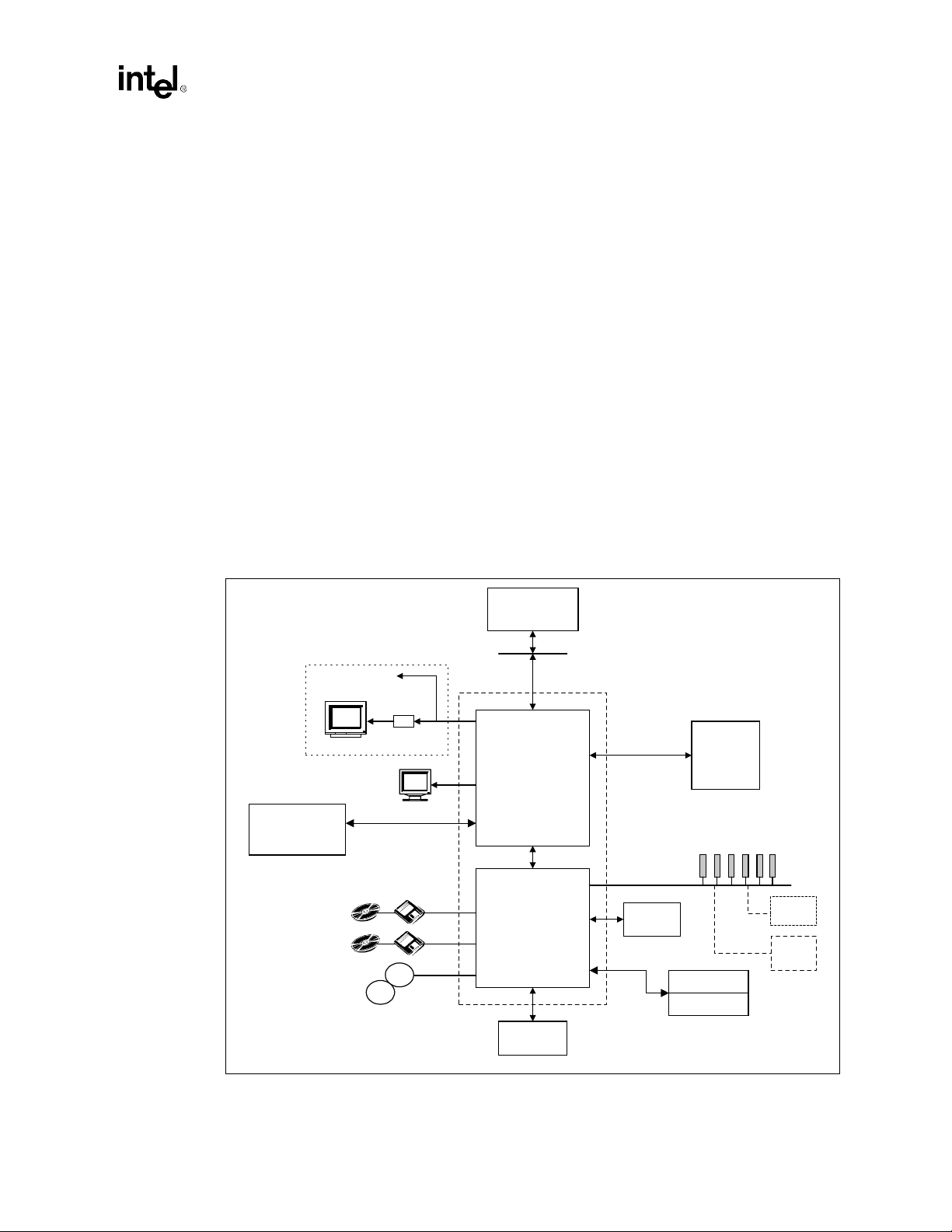
Figure 1-1. Intel 810A3 Chipset
Digital Video Out
TV
Display Cache
(4 MB SDRAM,100 MHz)
2 IDE Ports
Ultra ATA/66
2 USB
Ports
USB
Encoder
Display
USB
Processor
System Bus (66/100 MHz)
Intel® 810A3 Chipset
®
82810A3
Intel
(GMCH)
- Memory Controller
- Graphcs Controller
- 3D Engine
- 2D Engine
- Video Engine
ICH
(I/O Controller Hub)
64 Bit /
100 MHz Only
PCI Bus
Super
I/O
AC'97
System
Memory
PCI Slots
(ICH=6 Req/Gnt pairs)
Audio Codec
Modem Codec
ISA
Option
LAN
Option
FWH Flash
BIOS
Intel®810A3 Chipset Design Guide 1-9
Page 22

Introduction
1.3 Platform Initiatives
1.3.1 Hub Interface
As I/O speeds increase, the demand placed on the PCI bus by the I/O bridge has become
significant. With the addition of AC’97 and Ultra ATA/66, coupled with the existing USB, I/O
requirements could impact PCI bus performance. The Intel
architecture ensures that the I/O subsystem (both PCI and the integrated I/O features (IDE, AC’97,
USB, etc.)), receives adequate bandwidth. By placing the I/O bridge on the hub interface (instead
of PCI), the hub architecture ensures that both the I/O fu nctions integrated into the ICH and the PCI
peripherals obtain the bandwidth necessary for peak performance.
1.3.2 Manageability
The Intel 810A3 chipset platform i ntegrates s everal f unctions d esig ned to manag e the sys tem and
lower the total cost of ownership (TCO) of the system. These system management functions are
designed to report errors, diagnose the s ystem, and recov e r f rom system lo ckup s witho ut the aid of
an external microcontroller.
810A3 Chipset’s hub interface
TCO Timer
The ICH integrates a programmable TCO T imer. This timer is used to detect system locks. The first
expiration of the timer generates an SMI# which the system can use to recover from a software
lock. The second expiration of the timer causes a system reset to recover from a hardware lock.
Processor Present Indicator
The ICH looks for the processor to fetch the first instruction after reset. If the processor does not
fetch the first instruction, the ICH will reboot the system.
Function Disable
The ICH provides the ability to disable the following functions: AC'97 Modem , AC'97 Audio,
IDE, USB or SMBus. Once disabled, these functions no longer decode I/O, memory, or PCI
configuration space. Also, no interrupts or power management events are generated from the
disabled functions.
Intruder Detect
The ICH provides an input signal (INTRUDER#) that can be attached to a switch that is activated
by the system case being opened. The ICH can be programmed to gen erate an SMI# o r TCO ev ent
due to an active INTRUDER# signal.
Alert-On-LAN*
The ICH supports Alert-On-LAN*. In response to a TCO event (intruder detect, thermal event,
processor not booting) the ICH sends a hardcoded message over the SMBus. A LAN controller
supporting the Alert-On-LAN* protocol can decode this SMBu s message and s end a message ov er
the network to alert the network manager.
1-10
Intel®810A3 Chipset Design Guide
Page 23

1.3.3 AC’97
The Audio Codec ’97 (AC’97) Specification defines a digital link that can be used to attach an
audio codec (AC), a modem codec (MC), an audio/modem codec (AMC), or both an AC and an
MC. The AC’97 Specification defines the interface between the system logic and the audio or
modem codec known as the AC’97 Digital Link.
The ability to add cost-effective audio and modem solutions as the platform migrates away from
ISA is important. The AC’97 audio and modem components are software configurable, reducing
configuration errors. The Intel
replaces ISA audio and modem functionality, but also improves overall platform integration by
incorporating the AC’97 digital link. Using the Intel
link reduces cost and eases migration from ISA.
The ICH is an AC’97 compliant controller that supports up to two codecs with independent PCI
functions for audio and modem. The ICH communicates with the codec(s) via a digital serial link
called the AC-link. All digital audio/modem streams and command/status information is
communicated over the AC-lin k. Microph one in put and le ft and r ight au dio channel s are sup porte d
for a high quality t wo-speake r audi o solu tion. Wake on ring from suspend is al so s upported wit h an
appropriate modem codec.
Introduction
810A3 chipset’s AC’97 (with the appropriate codecs) not only
810A3 chipset’s integrated AC’97 digital
By using an audio codec, the AC’97 digital link allows for cost-effective, high-quality, in tegrated
audio on the Intel
implemented with the use of a modem codec. Several system options exist when implementing
AC’97. The Intel
810A3 chipset platform. In addition, an AC’97 soft modem can be
810A3 chipset’s integrated digital link allows two external codecs to be
connected to the ICH. The system designer can provide audio with an aud io codec (Figure 1-2 a) or
a modem with a modem codec (Figure 1-2 b). For systems requir ing both audio and a modem,
there are two solutions. The audio codec and the modem codec can be integrated into an AMC
(Figure 1-2 c), or separate audio and modem codecs can be connected to the ICH (Figure 1-2 d).
The modem implementation for different countries should be considered as telephone systems
vary. By using a split design, the audio codec can be on-board and the modem codec can be placed
on a riser. Intel is developing an AC’97 digital link connector. With a single integrated codec, or
AMC, both audio and modem can be routed to a connector near the rear panel where the external
ports can be located.
Intel®810A3 Chipset Design Guide 1-11
Page 24
Introduction
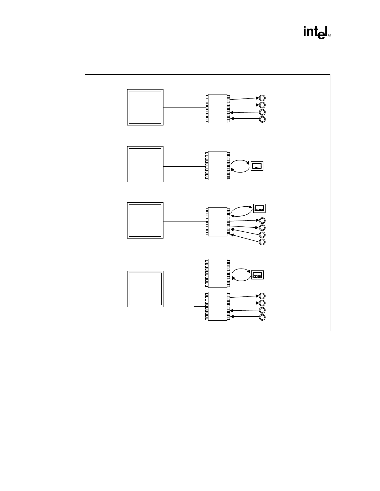
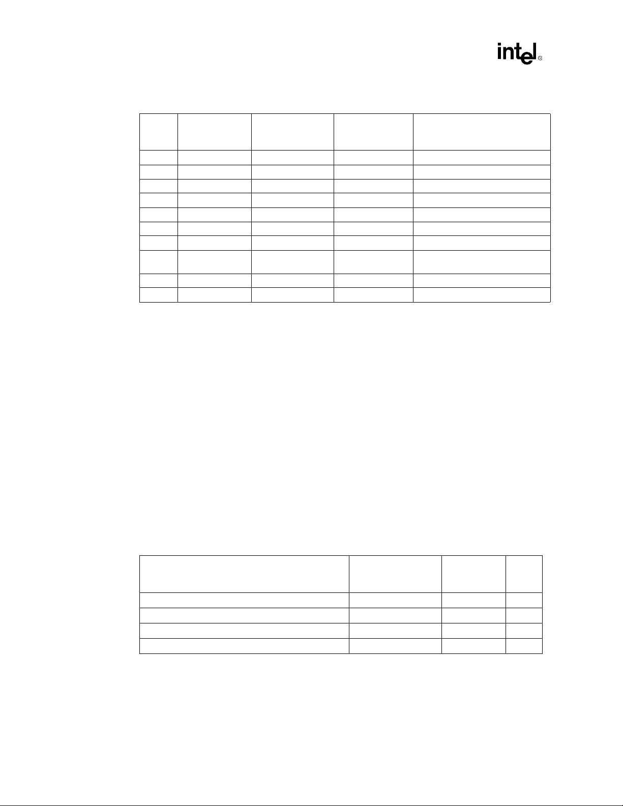
Figure 1-2. AC'97 with Audio and Modem Codec Connections
a) AC'97 With Audio Codec
ICH
(241 mBGA)
b) AC'97 With Modem Codec
ICH
(241 mBGA)
c) AC'97 With Audio/Modem Codec
ICH
(241 mBGA)
d) AC'97 With Audio and Modem Codec
ICH
(241 mBGA)
AC'97 Digital
Link
AC'97 Digital
Link
AC'97 Digital
Link
AC'97
Digital Link
Modem
Modem
Modem
AC'97
Audio
Codec
AC'97
Codec
AC'97
Audio/
Codec
AC'97
Codec
AC'97
Audio
Codec
Audio Ports
Modem Port
Modem Port
Audio Ports
Modem Port
Audio Ports
1.3.4 Low Pin Count (LPC) Interface
In the Intel 810A3 chipset platform, the Super I/O (SIO) component has m igrated to th e Low Pin
Count (LPC) interface. Migration to the LPC interface allows for lower cost Super I/O designs.
The LPC Super I/O component requires the same feature set as traditional Super I/O components.
It should include a keyboard and mouse controller, floppy disk controller and serial and parallel
ports. In addition to the Super I/O features, an integrated game port is recommended because the
AC’97 interface does not provide support for a game port. In a system with ISA audio, the game
port typically existed on the audio card. The fifteen pin game port connector provides for two
joysticks and a two-wire MPU-401 MIDI interface. Consult your preferred Super I/O vendor for a
comprehensive list of devices offered and features supported.
In addition, depending on system requirements, a device bay controller and USB hub could be
integrated into the LPC Super I/O component. For systems requiring ISA sup por t, an ISA-I RQ to
serial-IRQ converter is required. Potentially, this converter could be integrated into the Super I/O.
1-12
a_m_conn.vsd
Intel®810A3 Chipset Design Guide
Page 25

PGA370 Processor
Design Guidelines
2
Page 26

This page is intentionally left blank
Page 27

PGA370 Processor Design Guidelines
This chapter provides PGA370 processor design guidelines including the PGA370
socket, Layout Guidelines, BSEL implementation, CLKREF, Undershoot/Overshoot
requirements, Reset, Decoupling guidelines, Thermal/EMI differences, and Debug Port
changes. The layout guidelines are processor-specific and should be us ed in conjunction
with the Chapter 4, “Layout and Routing Guidelines”. For this chapter, the following
terminology applies:
•
Legacy PGA370 refers to today’s Intel® 810A3 chipset platforms utilizing the
PGA370 socket for the microprocessor. In general, these designs support 66/100
MHz host bus operation, VRM 8.2 DC-DC Converter Guidelines, and Intel
Celeron processors.
•
Flexible PGA370 refers to new generation Intel® 810A3/810E chipset platforms
utilizing the PGA370 socket and designed for microprocessor flexibility. In
general, these designs support 66/100 MHz bus operation for the Intel
chipset and 66/100/133 MHz host bus operation for the Intel
VRM 8.4 DC-DC Converter Guidelines and Intel
®
Intel
Pentium®
processor PGA single processor based designs.
III
®
Celeron, and
®
810E chipset ,
2.1 Electrical Differences for Flexible PGA370 Designs
®
810A3
2
®
There are several electrical changes between the legacy and flexible PGA370 design.
They include:
•
Changes to the PGA370 socket pin definitions. Intel® Pentium®
utilize a superset of the Intel
•
Addition of VTT (AGTL+ termination voltage) delivery to the PGA370 socket.
•
Additional PLL reference voltage, 1.25V, on new CLKREF pin.
•
More stringent undersh oot/oversh oot requirements for CMOS and AGTL+ signals.
•
Addition of on-die Rtt (AGTL+ termination resistors) for the Intel® Pentium®
processor. Requirement remains for on-motherboard Rtt implementation if
supporting the Intel
processors, the reset signals (RESET#) still requires termination to V
motherboard.
Celeron processor pin definition.
Celeron (PPGA). If only supporting Intel® Pentium®
processors
III
on the
TT
III
III
Intel®810A3 Chipset Design Guide 2-1
Page 28
PGA370 Processor Design Guidelines
2.2 PGA370 Socket Definition Details
The following tables compare legacy pin names and functions to new flexible pin names and
functions. Designers need to pay close attention to the notes section for this table for compatibility
concerns regarding these pin changes.
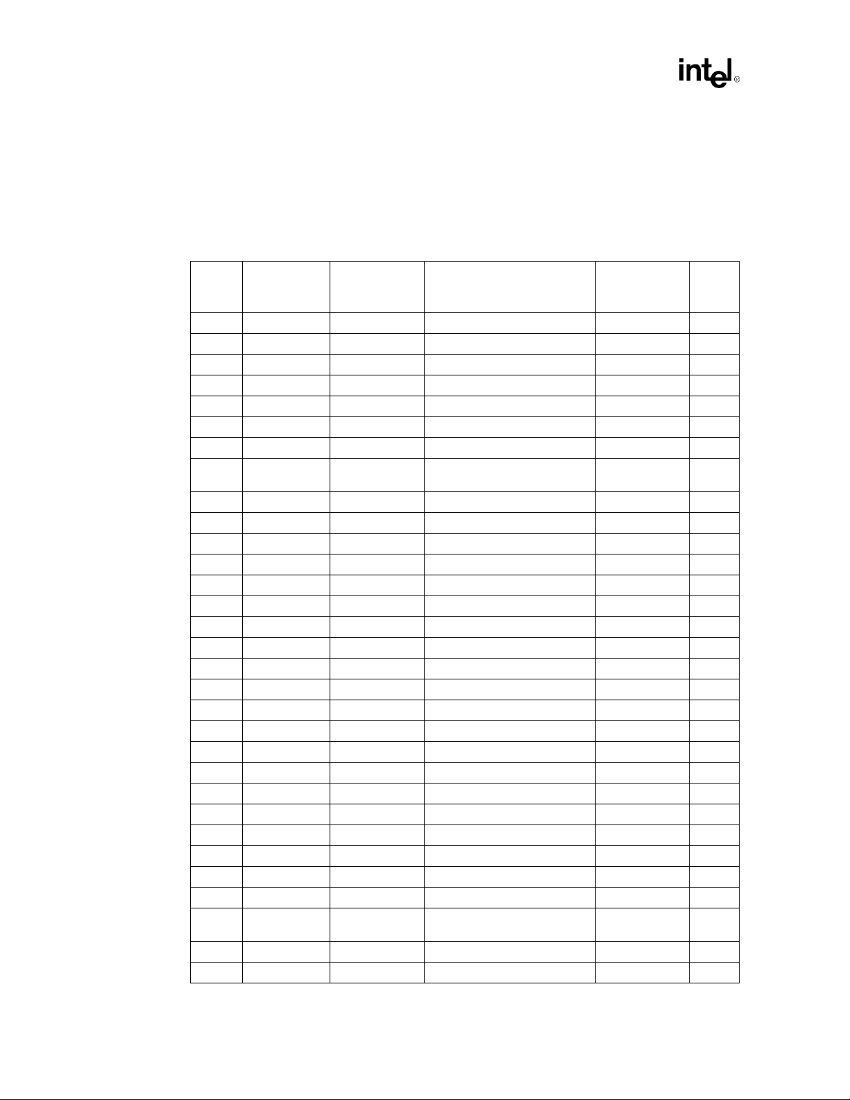
Table 2-1. Platform Pin Definition Comparison for Single Processor Designs
Pin #
A29 Reserved DEP7# Data bus ECC data AGTL+, I/O 2
A31 Reserved DEP3# Data bus ECC data AGTL+, I/O 2
A33 Reserved DEP2# Data bus ECC data AGTL+, I/O 2
AC1 Reserved A33# Additional AGTL+ address AGTL+, I/O 2
AC37 Reserved RSP# Response parity AGTL+, I 2
AF4 Reserved A35# Additional AGTL+ address AGTL+, I/O 2
AH20 Reserved VTT AGTL+ termination voltage Power
AH4 Reserved RESET#
AJ31 GND BSEL1 System bus frequency select CMOS, I/O 1
AK16 Reserved VTT AGTL+ termination voltage Power
AK24 Reserved AERR# Address parity error AGTL+, I/O 2
AL11 Reser ved AP0# Address parity AGTL+, I/O 2
AL13 Reserved VTT AGTL+ termination voltage Power
AL21 Reserved VTT AGTL+ termination voltage Power
AM2 GND Reserved Reserved Reserved 1
AN11 Reserved VTT AGTL+ termination voltage Power
AN13 Reserved AP1# Address parity AGTL+, I/O 2
AN15 Reserved VTT AGTL+ termination voltage Power
AN23 Reserved RP# Request parity AGTL+, I/O
B36 Reserved BINIT# Bus initialization AGTL+, I/O 2
C29 Reserved DEP5# Data bus ECC data AGTL+, I/O 2
C31 Reserved DEP1# Data bus ECC data AGTL+, I/O 2
C33 Reserved DEP0# Data bus ECC data AGTL+, I/O 2
E29 Reserved DEP6# Data bus ECC data AGTL+, I/O 2
E31 Reserved DEP4# Data bus ECC data AGTL+, I/O 2
G35 Reserved VTT AGTL+ termination voltage Power
V4 Reserved BERR# Bus er ror AGTL+, I/O 2
W3 Reserved A34# Additional AGTL+ address AGTL+, I/O 2
X4 RESET# RESET2#
X6 Reserved A32# Additional AGTL+ address AGTL+, I/O 2
Y33 GND CLKREF 1.25V PLL reference Power 1
Legacy
PGA370
pin name
Flexible
PGA370
pin name
Function Type Notes
Processor reset (Intel
®
Pentium
Processor reset (Value
processors)
III)
®
AGTL+, I 3
AGTL+, I 3
2-2
Intel®810A3 Chipset Design Guide
Page 29
PGA370 Processor Design Guidelines
NOTES:
1. These signals were previously defined as ground (Vss) connections in legacy designs utilizing the PGA370
socket to provide termination for unused inputs. For new Flexible PGA370 designs, use the new signal
definitions. These new signal definitions are backwards compatible with the Intel® Celeron processor
(PPGA).
2. While these signals are not used with Intel
support these functions. Only the Intel
platform.
3. The AGTL + reset signal, RESET#, is delivered to pin X4 on Legacy PGA370 designs. On Flexible PGA370
designs it is delivered to X4 and AH4 pins. See Figure 2-1 for more details.
®
810A3 chipset designs, they are available for chipsets that do
®
Pentium® III processor offers these capabilities in the PGA370
2.2.1 Processor Pin Definition Comparison
T a ble 2-2. Processor Pin Definition Comparison
®
Intel
Pin #
A29 Reserved Reserved DEP7# Data bus ECC data
A31 Reserved Reserved DEP3# Data bus ECC data
A33 Reserved Reserved DEP2# Data bus ECC data
AA33 Reserved Reserved VTT AGTL+ termination voltage
AA35 Reserved Reserved VTT AGTL+ termination voltage
AC1 Reserved Reserved A33# Additional AGTL+ address
AC37 Reserved Reserved RSP# Response parity
AF4 Reserved Reserved A35# Additional AGTL+ address
AH20 Reserved Reserved VTT AGTL+ termination voltage
AH4 Reserved Reserved RESET#
AJ31 GND BSEL1 BSEL1 S ystem bus fr equency select
AK16 Reserved Reserved VTT AGTL+ termination voltage
AK24 Reserved Reserved AERR# Address parity error
AL11 Reserved Reserved AP0# Address parity
AL13 Reserved Reserved VTT AGTL+ termination voltage
AL21 Reserved Reserved VTT AGTL+ termination voltage
AM2 GND Reserved Reserved Reserved
AN11 Reserved Reserved VTT AGTL+ termination voltage
AN13 Reserved Reserved AP1# Address parity
AN15 Reserved Reserved VTT AGTL+ termination voltage
AN21 Reserved Reserved VTT AGTL+ termination voltage
AN23 Reserved Reserved RP # Request parity
B36 Reserved Reserved BINIT# Bus initialization
C29 Reserved Reserved DEP5# Data bus ECC data
C31 Reserved Reserved DEP1# Data bus ECC data
C33 Reserved Reserved DEP0# Data bus ECC data
E23 Reserved Reserved VTT AGTL+ termination voltage
E29 Reserved Reserved DEP6# Data bus ECC data
E31 Reserved Reserved DEP4# Data bus ECC data
CeleronTM
(PPGA)
pin name
Intel
®
pin name
Pentium® III
128K
Intel
®
pin name
Pentium® III
256K
Function
Processor reset (Intel
processor-256K)
Pentium III
Intel®810A3 Chipset Design Guide 2-3
Page 30
PGA370 Processor Design Guidelines
Table 2-2. Processor Pin Definition Comparison (Continued)
®
Intel
Pin #
G35 Reserved Reserved VTT AGTL+ termination voltage
S33 Reserved Reserved VTT AGTL+ termination voltage
S37 Reserved Reserved VTT AGTL+ termination voltage
U35 Reserved Reserved VTT AGTL+ termination voltage
U37 Reserved Reserved VTT AGTL+ termination voltage
V4 Reserved Reserved B ERR# Bus error
W3 Reserved Reserved A34# Additional AGTL+ address
X4 RESET# RESET# RESET2#
X6 Reserved Reserved A32# Additional AGTL+ address
Y33 GND Reserved CLKREF 1.25V PLL reference
CeleronTM
(PPGA)
pin name
Intel
®
pin name
Pentium® III
128K
Intel
®
pin name
Pentium® III
256K
Function
Processor reset (Celeron PPGA,
Intel Pentium III 128K)
2.2.2 Layout Guidelines for Intel® Pentium® III Processors
The following layout guide supports designs using Intel Celeron processors and Intel®
Pentium
66 MHz for the Intel
The solution proposed in this segment requires the motherboard design to terminate the system bus
AGTL+ sig na l s with a 56 Ω ±5% Rtt. The Intel
®
processor with the Intel 810A3 chipset. The solution covers system bus speeds of
III
Celeron processor and 100 MHz for the Intel® Pentium®
®
Pentium®
processor must also be configured
III
processors.
III
to 110Ω internal Rtt.
Note: 133 MHz system bus frequency is not supported on the Intel
810A3 chipset.
Initial Timing Analysis
Table 2-3 lists the AGTL+ component timings of the processors and 82810A3 GMCH defined at
the pins. These timings are for r eference only; obtain each processor’s specifications fr om its
respective processor Electrical, Mechanical, and Thermal Specification and appropriate
Intel
810A3 chipset component specification.
Table 2-3. Intel® Pentium® III Processor and GMCH AGTL+ Parameters for Example
Calculations
®
Intel
IC Parameters
Clock to Output maximum (T
Clock to Output minimum (T
Setup time (T
Hold time (T
) 1.20 2.72 2,3
SU_MIN
) 1.0 0.10
HOLD
Pentium® III
Processor Core at
100 MHz System Bus
)3.255.352
CO_MAX
)0.401.272
CO_MIN
GMCH at
100 MHz
System Bus
Notes
2-4
NOTES:
1. A ll times in nanoseconds.
2.
Numbers in table are for reference only
appropriate component documentation for valid timing parameter values.
3. T
= 2.72 ns assumes the GMCH sees a minimum edge rate equal to 0.3 V/ns.
SU_MIN
. These timing parameters are subject to change. Check the
Intel®810A3 Chipset Design Guide
Page 31

PGA370 Processor Design Guidelines
Table 2-4 gives an example AGTL+ initial maximum flight time and Table 2-5 is an example
minimum flight time calculation for a 100 MHz processor system using the Intel
processor/Intel
jitter were used. Clock skew and clock jitter values are dependent on the clock components
and distribution method chos en for a particular design and must be budgeted into the initial
timing equations as appropriate for each design.
Table 2-4 and Table 2-5 are derived assuming:
•
CLK
SKEW
two host clock outputs together (“ganging”) at clock driver output pins, and the PCB clock
routing skew is 150 ps. System timing budget must assume 0.175 ns of clock driver skew if
outputs are not tied together and a clock driver that meets the CK810 Clock Synthesizer/Driver
Specification is being used.)
•
CLK
JITTER
See the appropriate Intel
Specification for details on clock skew and jitter specifications. Exact details of host clock r outi ng
topology are provided with the platform design guideline.
Table 2-4. Example T
Driver Receiver
Processor GMCH 10 3.25 2.72 0.20 0.25 0.40 3.18
GMCH Processor 10 5.35 1.20 0.20 0.25 0.40 2.60
810A3 chipset system bus. Note that assumed values for clock skew and clock
Pentium
= 0.20 ns (Note: Assumes clock driver p in-to-p in skew is redu ced to 50 ps by tying
= 0.250 ns
810A3 chipset documentation, and CK810 Clock Synthesizer/Driver
Clk
1
SKEW
Clk
JITTERMADJ
Recommended
T
FLT_MAX
FLT_MIN
Calculations FOR 100 MHz Bus
Clk
Period
T
2
CO_MAXTSU_MIN
III
3
NOTES:
1. A ll times in nanoseconds.
2. BCLK period = 10 ns @ 100 MHz.
3. The flight times in this column include margin to account for the following phenomena that Intel has observed
when multiple bits are switching simultaneously. These multi-bit effects can adversely affect flight time and
signal quality and are sometimes not accounted for in simulation. Accordingly, maximum flight times depend
on the baseboard design and additional adjustment factors or margins are recommended.
SSO push-out or pull-in.
•
Rising or falling edge rate degradation at the receiver caused by inductance in the current return path,
•
requiring extrapolation that causes additional delay.
Cross-talk on the PCB and internal to the package can cause variation in the signals.
•
There are additional effects that
should be budgeted as appropriate to the baseboard design. Examples include:
The effective board propagation constant (S
•
— Dielectric constant (
— The type of trace connecting the components (stripline or microstrip).
— The length of the trace and the load of the components on the trace. Note that the board propagation
constant multiplied by the trace length is a
the flight time.
Table 2-5. Example T
Driver Receiver T
Processor GMCH 0.10 0.15 0.35 0.40 0.20
GMCH Proces sor 1.0 0.15 0.35 1.27 0.23
NOTES:
1. A ll times in nanoseconds.
FLT_MIN
may not
) of the PCB material.
ε
r
necessarily be covered by the multi-bit adjustment factor and
), which is a function of:
EFF
component
of the flight time
Calculations (Frequency Independent)
HOLD
Clk
SKEW
Clk
but not necessarily equal to
1
SHIFTTCO_MIN
Recommended
T
FLT_MIN
Intel®810A3 Chipset Design Guide 2-5
Page 32

PGA370 Processor Design Guidelines
2.2.2.1 Determine General Topology and Layout
In the SET (Single Ended Termination) topology for the 37 0-pin socket (P GA370), t he termi nation
should be placed close to the processor on the motherboard. There is no termination present at the
chipset end of the network. Due to the lack of termination, SET will exhibit much more ringback
than the dual terminated topology. Extra care is required in SET simulations to make sure that the
ringback specs are met under the worst case signal quality conditions. Intel
designs require all AGTL+ signals to be terminated with a 56Ω termination on the motherboard.
To ensure processor signal integrity requirements it is highly recommended that all system bus
signal segments to be referenced to the ground plane for the entire route (Chapter 5,
“Advanced System Bus Design” for details).
Figure 2-1. Topology for 370-Pin Socket Designs with Single Ended Termination (SET)
Vtt
56
Ω
GMCH
L(1): Z0=60 Ω ±15%.
L1
L3
L2
PGA370
Socket
810A3 chipset
Table 2-6. Segment Descriptions and Lengths for Figure 2-1
Segment Description Min length (inches) Max length (inches)
L1 + L2 GMCH to Rtt Stub 1.90 4.50
L2 PGA370 Pin to Rtt stub 0.0 0.20
L3 Rtt Stub length 0.50 2.50
NOTES:
1. A ll AGTL+ bus signals should be referenced to the ground plane for the entire route. See Chapter 5,
“Advanced System Bus Design”.
•
AGTL+ signals should be routed with trace lengths within the range specified fo r L1+L2 fro m
the processor pin to the chipset.
•
Use an intragroup AGTL+ spacing to line width to dielectric thickness ratio of at least 2:1:1
for microstrip geomety . If
= 4.5, this should limit coupling to 3.4%. For example, intragroup
ε
r
AGTL+ routing could use 10 mil spacing, 5 mil tr aces, and a 5 m il prepr eg b etween the s ign al
layer and the plane it references (assuming a 4-layer motherboard design).
•
The trace width is recommended to be 5 mils and not greater than 6 mils.
Table 2-7 contains the trace width:space ratios assumed for this topology. The crosstalk cases
considered in this guideline involve three types: Intragroup AGTL+, Intergroup AGTL+, and
AGTL+ to non-AGTL+. Intragroup AGTL+ crosstalk involves interference between AGTL+
signals within the same group. Intergroup AGTL+ crosstalk involves interference from AGTL+
signals in a particul ar group to AGTL+ sign als in a dif fer ent group . An example of AGTL+ t o nonAGTL+ crosstalk is when CMOS and AGTL+ signals interfere with each other.
1
T able 2-7. Trace Width (Space Guidelines)
Crosstalk Type Trace Width:Space Ratios
Intragroup AGTL+ signals (same group AGTL+) 5:10 or 6:12
Intergroup AGTL+ signals (different group AGTL+) 5:15 or 6:18
AGTL+ to non-AGTL+ processor signals 5:20 or 6:24
2-6
Intel®810A3 Chipset Design Guide
Page 33

PGA370 Processor Design Guidelines
2.2.2.2 Motherboard Layout Rules for AGTL+ Signals
Minimizing Crosstalk
The following general rules will minimize the impact of crosstalk in the high speed AGTL+ bus
design:
•
Maximize the space between traces. Maintain a minimum of 0.010” between traces wherever
possible. It may be necessary to use tighter spacings when routing between component pins.
•
Avoid parallelism between signals on adjacent layers.
•
Since AGTL+ is a low signal swing technology, it is important to isolate AGTL+ signals from
other signals by at least 0.025”. This will avoid coupling from signals that have larger voltage
swings, such as 5V PCI.
•
Select a board stack-up that minimizes the coupling between adjacent signals.
•
Route AGTL+ address, data and control signals in separate groups to minimize crosstalk
between groups. The Pentium
the address lines and corresponding control lines could be driven by a different agent than the
data lines and their corresponding control lines.
Additional Considerations
processor uses a split transaction bus. In a given clock cycle,
III
•
Distribute VTT with a wide trace. A 0.050” minimum trace is recommended to minimize DC
losses. Route the V
capacitors. Guidelines for V
Power Distribution Guidelines.”
•
Place resistor divider pairs for V
is needed at the processor(s). V
decoupling capacitors. Guidelines for V
1 Processor Power Distribution Guidelines.”
•
Special Case AGTL+ signals for simulation: There are six AGTL+ signals that can be driven
by more than one agent simultaneously. These signals may require extra attention during the
layout and validation portions of the design. When a signal is asserted (driven low) by two
agents on the same clock edge, the two falling wave fronts will meet at some point on the bus.
This can create a large undershoot, followed by ringback which may violate the ringback
specifications. This “wired-OR” situation should be simulated for the following signals:
AERR#, BERR#, BINIT#, BNR#, HIT#, and HITM#.
trace to all components on the host bus. Be sure to include decoupling
TT
distribution and decoupling are contained in “Slot 1 Processor
TT
generation at the MCH component. No V
REF
is generated locally on the processor. Be sure to include
REF
distribution and decoupling are cont ained in “Slot
REF
generation
REF
Intel®810A3 Chipset Design Guide 2-7
Page 34

PGA370 Processor Design Guidelines
2.2.2.3 Motherboard Layout Rules for Non-AGTL+ (CMOS) Signals
Non-AGTL+ (CMOS) Signals
Route these signals on any layer or any combination of layers.
Table 2-8. Routing Guidelines for Non-AGTL+ Signals
Signal Trace Width Spacing to Other Traces Trace Length
A20M# 5 mils 10 mils 1” to 9”
FERR# 5 mils 10 mils 1” to 9”
FLUSH# 5 mils 10 mils 1” to 9”
IERR# 5 mils 10 mils 1” to 9”
IGNNE# 5 mils 10 mils 1” to 9”
INIT# 5 mils 10 mils 1” to 9”
LINT[0] (INTR) 5 mils 10 mils 1” to 9”
LINT[1] (NMI) 5 mils 10 mils 1” to 9”
PICD[1:0] 5 mils 10 mils 1” to 9”
PREQ# 5 mils 10 mils 1” to 9”
PWRGOOD 5 mils 10 mils 1” to 9”
SLP# 5 mils 10 mils 1” to 9”
SMI# 5 mils 10 mils 1” to 9”
STPCLK 5 mils 10 mils 1” to 9”
THERMTRIP# 5 mils 10 mils 1” to 9”
2.2.2.4 THRMDP and THRMDN
These traces (THRMDP and THRMDN) route the processor’s thermal diode connections. The
thermal diode operates at very low currents and may be suscep tible to cros stalk. T he traces sho uld
be routed close together to reduce loop area and inductance (Refer to Figure 2-2).
Figure 2-2. Routing for THRMDP and THRMDN
Signal Y
THRMDP
THERMDN
Signal Z
•
Rule
— Length Equalization route these traces parallel ±0.5”
— Layer route both on the same layer
1 -- Maximize (min - 20 mils)
2 -- Minimize
1 -- Maximize (min - 20 mils)
2-8
Intel®810A3 Chipset Design Guide
Page 35

PGA370 Processor Design Guidelines
2.2.2.5 Additional Considerations
•
Distribute Vtt with a wide trace. A 0.050” minimum trace is recommended to minimize DC
losses. Route the V
trace to all components on the host bus. Be sure to include decoupling
TT
capacitors.
•
The VTT voltage should be 1.5V ±3% for static conditions, and 1.5V ±9% for transient
condition.
•
Place resistor divider pairs for V
generation at the GMCH component. V
REF
delivered to the processor.
2.2.3 Undershoot/Overs hoot Requirements
Undershoot and overshoot specifications become more critical as the process technology for
microprocessors shrinks due to thinn er gate oxide. Violating these undershoot and overshoot lim its
will degrade the life expectancy of the processor.
2.2.4 BSEL[1:0] Implementation for PGA370 Designs
REF
is also
While the BSEL0 signal is still connected to the PGA370 socket, the Intel® Pentium®
does not utilize it. Only the Intel
®
Pentium®
Intel
However, the Intel
III
processors are 3.3V tolerant for these signals, as are the CK810 and GMCH.
Celeron processor requires 2.5V logic levels on the BSEL signals.
Celeron processor (PPGA) utilizes the BSEL0 signal. The
A new clock synthesizer, the CK810, has been designed to support selections of 66 MHz and
100 MHz. The REF input pin has been redefined to be a frequency selection strap (BSEL1) dur ing
power-on and then becomes a 14 MHz reference clock output. This maintains pin compatib ility
with the CK810 clock synthesizer. Figure 2-3 details the new BSEL[1:0] circuit design for
Flexible PGA370
designs.
Note that BSEL[1:0] are now pulled up using 1 KΩ resistors.
Figure 2-3 shows the GMCH and processor straps for selecting the system bus frequency:
Figure 2-3. BSEL[1:0] Circuit Implementation for PGA370 Designs
3.3V
3.3V
1
ΚΩ
1
ΚΩ
Processor
BSEL0 BSEL1
10 K
Ω
10 K
10 K
Ω
REF
CK810
SEL0
Ω
14 MHz
REFCLK
SEL1
3.3V
III
processor
8.2 K
Ω
LMD29 LMD13
GMCH
Intel®810A3 Chipset Design Guide 2-9
Page 36

PGA370 Processor Design Guidelines
2.2.5 CLKREF Circuit Implementation
The CLKREF input requires a 1.25V source. It can be generated from a voltage divider on the
Vcc2.5 or Vcc3.3 sources utilizing 1% tolerance resistors. A 4.7 uF decoupling capacitor should
be included on this input. See Figure 2-4 and Table 2-9 for example CLKREF circuits. Do not use
Vtt as the source for this reference!
Figure 2-4. Examples for CLKREF Divider Circuit
PGA370
Vcc2.5
150
150
CLKREF
Y33
Ω
Ω
4.7uF
Vcc3.3
R1
R2
T able 2-9. Example Resistor Values for CLKREF Divider Circuit (3.3V Source)
R1 (Ω)R2 (
182 110 1.243
301 182 1.243
374 221 1.226
499 301 1.242
) CLKREF Voltage (V)
Ω
2.2.6 Undershoot/Overshoot Requirements
PGA370
CLKREF
Y33
4.7uF
2-10
The Intel® Pentium®
processor has more restrictive overshoot and undershoot requirements for
III
system bus signals than previous processors. These requirements stipulate that a signal at the
output of the driver buffer and at the input of the receiver buffer must not exceed a maximum
absolute overshoot voltage limit (2.1V) and a minimum absolute undershoot voltage limit (-
0.35V). Exceeding these limits will cause damage to the Intel
also a time dependent, non-linear overshoot and undershoot requirement that is dependent on the
amplitude and duration of the overshoot/undershoot. See the Intel
®
Pentium®
®
Pentium®
processor. There is
III
processor
III
datasheet for more details on overshoot/undershoot s pecificatio ns.
Intel®810A3 Chipset Design Guide
Page 37

PGA370 Processor Design Guidelines
2.2.7 Connecting RESET# and RESET2# on a Flexible PGA370
Design
Intel 810A3 chipset platform designs that support both the Intel Celeron™ processor and
Pentium
processor mut route the AGTL+ reset signal from the chipset to two pins on the
III
processor, as well as to the ITP connector. This reset segnal is conneted to pins AH4 (RESET#)
and X4 (RESET#) at the PGA370 socket (see Figure 2-5).
Figure 2-5. RESET# Schematic for PGA370 Designs
lenITP
V
Chipset
Parameter
lenCS
lenITP
lenCPU
cs_rtt_stub
CPU_rtt_stub
TT
91
Ω
cs_rtt_stub
lenCS
Minimum
0.5
1
0.5
0.5
0.5
240
Ω
cpu_rtt_stub
lenCPU
Maximum
1.5
3
1.5
1.5
1.5
V
TT
91
Ω
22
Ω
10 pF
ITP
Daisy Chain
Pin X4
Processor
Pin AH4
On legacy Intel
processors), RESET# is delivered only to pin X4. On Flexible Intel
(ones that have support fo r both Inte l
810A3 chipset platforms (ones that only have support for Intel Celeron™
Celeron™ processor and the In tel Penitum II processors)
using a 370-pin socket, RESET# is delivered to both pins X4 and AH4.
2.2.8 Reset Strapping Options
LMD26 on the GMCH is used as a strap at reset to determine whether the system board is
supporting a 370-pin socket or an SC242 connector:
LMD26: 0 or floating = 370-pin socket [leave as no connect]
1 = SC242 connector [pullup to 3.3 V thro ugh an (approximately) 8. 2KΩ
pullup resistor]
It is recommended that this circuit be added to new motherboard designs using either the SC242
connector or the PGA370 socket. The resistor location can be left unpopulated for the PGA370
socket. This allows flexibility for processor timing parameters.
810A3 Chipset platforms
Intel®810A3 Chipset Design Guide 2-11
Page 38

PGA370 Processor Design Guidelines
2.2.9 Voltage Regulation Differences
The Intel® Pentium®
voltage regulator to be compliant with Intel VRM 8.4 DC-DC Converter Design Guidelines
revision 1.5 or greater. Important points to note regarding VRM 8.4 are:
•
Intel Celeron processor (PPGA) operates at VccCORE of 2.0V, Intel® Celeron™
processor (FC-PGA) operates at 1.5V, and Intel
•
Requirement for VRM 8.4 to support the Intel® Pentium®
650 MHz has changed from previous processors. Transient and static tolerances are tighter
than VRM 8.2.
•
Additional motherboard decoupling required to meet VRM 8.4.
(FC-PGA w/256K L2 cache) processor requires the VRM or on-board
III
®
Pentium®
-256K operates at 1.6V.
III
processor at speeds greater than
III
2.2.10 Decoupling Guidelines for Flexible PGA370 Designs
These are preliminary decoupling guidelines for Flexible PGA370 designs and are estimated to
meet VRM 8.4 V1.6 flexible motherboard guidelines.
2.2.10.1 VCC
•
Ten or more 4.7 uF capacitors in 1206 packages.
All capacitors should be placed within the PGA370 socket cavity and mo unted on the p rimary
side of the motherboard. The capacitors are arranged to minimize the overall inductance
between VCC
Figure 2-6. Capacitor Placement on the Motherboard
Decoupling Design
CORE
/Vss power pins, as shown in Figure 2-6.
CORE
2-12
Intel®810A3 Chipset Design Guide
Page 39

2.2.10.2 Vtt Decoupling Design
For Itt = 3.0 A (max).
•
Nineteen - 0.1 uF capacitors in 0603 packages placed within 200 mils of AGTL+ termination
R-pack’s, one capacitor for every two R-packs. These capacitors are shown on the outer
exterior of Figure 2-6. These are located on the motherboard.
Vref Decoupling Design
•
Four - 0.1uF capacitors in 0603 package placed near V
2.2.11 Thermal/EMI Differences
Heatsink requirements will be different for FC-PGA processors from previous processors using
PPGA packaging. Refer to the processor datasheet for specific guidelines.
•
Increased power density for Intel® Pentium®
•
Different thermal design verification for FC-PGA compared to PPGA packaged processors.
®
Intel
Pentium®
Celeron processors).
•
New heatsink for FC-PGA package which is not backwards compatible with PPGA
processors.
•
New heatsink clips for FC-PGA processor heatsinks.
processors are specified using Tjunction versus Tcase (used with Intel
III
PGA370 Processor Design Guidelines
pins (within 500 mils).
REF
processor (approximately 27 W/cm2).
III
®
Intel®810A3 Chipset Design Guide 2-13
Page 40

PGA370 Processor Design Guidelines
2.2.12 Debug Port Changes
Due to the lower voltage technology employed with the Intel® Pentium®
required to support the debug port. Previously, the test access port (T AP) signals used 2.5V log ic.
This is the case with the Intel
Celeron processor in the PPGA package. Intel® Pentium®
utilizes 1.5V logic levels on the TAP. As a result, a new ITP connector is to be used on flexible
PGA370 designs. The new 1.5V co nne ctor is the mi rror imag e of th e older 2.5 V connect or. Either
connector will fit into the same printed circuit board layout. Just the pin numbers would change, as
can be seen in the drawing below:
Figure 2-7. TAP Connector Comparison
2.5V connector, AMP 104068-3 Vertical Plug, Top View
2 4 6 8 10 22
RESET#
RESET#
Caution: The Intel
Previous ITPs are designed to work with higher volt ages and may damag e the processor if they are
connected to an Intel
®
Pentium®
1 3 5 7 9 13 15 17
1.5V connector, AMP 104078-4 Vertical Receptacle, Top View
1 3 5 7 9 13 15 17
2 4 6 8 10 22
processor requires an in-target probe (ITP) with a 1.5V tolerant buffer.
III
®
Pentium
®
Specification EMTS) for more information regarding the debug port.
processor, changes are
III
12 14 16 18 20
11 19
11 19
12 14 16 18 20
processor. See the Electrical, Mechanical and Thermal
III
24 26 28 30
21 23 25 27 29
21 23 25 27 29
24 26 28 30
III
2-14
Intel®810A3 Chipset Design Guide
Page 41

SC242 Processor
Design Guidelines
3
Page 42

This page is intentionally left blank
Page 43

SC242 Processor Design Guidelines
SC242 Processor Design Guidelines
This chapter provides SC242 processor design guidelines in cluding Layout Guidelines, general
topology, minimizing crosstalk, motherboard layout rules for non-AGTL+ signals, THRMDP and
THRMDN, and motherboard frequency select for SC242 designs. The layout guidelines are
processor-specific and should be used in conjunction with the Chapter 4, “Layout and Routing
Guidelines”. See Chapter 5, “Advanced System Bus Design” for more details on AGTL+ layout
guidelines.
3.1 Intel® Pentium® III Processors Layout Guidelines
The following layout guide supports designs using Intel Pentium®
SC242 connector and Intel
Initial Timing Analysis
Table 3-1 lists the AGTL+ component timings of the processors and GMCH defined at the pins.
These timings are for reference only; obtain each processor’s specifications from its
respective Electrical, Mechanical, and Thermal Specification and appropriate Intel
chipset component specification.
T able 3-1. Intel
Calculations
Clock to Output maximum (T
Clock to Output minimum (T
Setup time (T
Hold time (T
810A3 chipset at system bus speeds of 100MHz.
®
Pentium® III Processor and GMCH AGTL+ Parameters for Example
1
®
Pentium III processor
IC Parameters
) 2.70 3.63 2
CO_MAX
) -0.10 0.50 2
CO_MIN
) 1.20 2.27 2,3
SU_MIN
) 0.80 0.28
HOLD
Intel
core at 100 MHz System Bus
processors utilizing the
III
GMCH Notes
810A3
3
NOTES:
1. A ll times in nanoseconds.
2.
Numbers in table are for reference only
appropriate component documentation for valid timing parameter values.
3. T
= 2.72 ns assumes the GMCH sees a minimum edge rate equal to 0.3 V/ns.
SU_MIN
Table 3-2 gives an example AGTL+ initial maximum flight time and Table 3-3 is an example
minimum flight time calculation for a 100 MHz, uni-processor system using Intel
processor/Intel
®
810A3 Chipset system bus. Note that assumed values for clock skew and clock
. These timing parameters are subject to change. Please check the
Pentium
III
jitter were used. Clock skew and clock jitter values are dependent on the clock components
and distribution method chos en for a particular design and must be budgeted into the initial
timing equations as appropriate for each design.
Intel®810A3 Chipset Design Guide 3-1
Page 44

SC242 Processor Design Gui deline s
Table 3-2 and Table 3-3 are derived assuming:
•
CLK
= 0.2 ns (Note: Assumes clock driver pin-to-pin skew is reduced to 50 ps by tying
SKEW
two host clock outputs together (“ganging”) at clock driver output pins, and the PCB clock
routing skew is 150 ps. System timing budget must assume 0.175 ns of clock driver skew if
outputs are not tied together and a clock driver that meets the CK810 clock driver specification
is being used.)
•
CLK
JITTER
= 0.250 ns
Some clock driver components may not support ganging the outputs together. Be sure to
verify with your clock component vendor before ganging the outputs. See the respective
processor’s Electrical, Mechanical, and Thermal Specification, appropriate Intel
documentation, and CK810 Clock Synthesizer/Driver Specification for details on clock skew and
jitter specifications.
810A3 chipset
Table 3-2. Example T
Driver Receiver
Processor GMCH 7.50 2.70 2.27 0.20 0.25 0.40 1.68
GMCH Processor 7.50 3.63 1.20 0.20 0.25 0.40 1.82
NOTES:
1. A ll times in nanoseconds.
2. B CLK period = 10 ns @ 100 MHz.
3. The flight times in this column include margin to account for the following phenomena that Intel has observed
when multiple bits are switching simultaneously. These multi-bit effects can adversely affect flight time and
signal quality and are sometimes not accounted for in simulation. Accordingly, maximum flight times depend
on the baseboard design and additional adjustment factors or margins are recommended.
SO push-out or pull-in.
•
Rising or falling edge rate degradation at the receiver caused by inductance in the current return path,
•
requiring extrapolation that causes additional delay.
Cross-talk on the PCB and internal to the package can cause variation in the signals.
•
There are additional effects that
should be budgeted as appropriate to the baseboard design. Examples include:
The effective board propagation constant (S
•
— Dielectric constant (
— The type of trace connecting the components (stripline or microstrip).
— The length of the trace and the load of the components on the trace. Note that the board propagation
constant multiplied by the trace length is a
the flight time.
Table 3-3. Example T
Driver Receiver T
Processor GMCH 0.28 0.20 -0.10 0.58
GMCH Processor 0.80 0.20 0.50 0.50
FLT_MAX
FLT_MIN
Calculations for 100 MHz Bus
Clk
Period
ε
T
2
CO_MAXTSU_MIN
may not
) of the PCB material.
r
necessarily be covered by the multi-bit adjustment factor and
EFF
), which is a function of:
component
1
Clk
of the flight time
SKEW
Clk
Calculations (Frequency Independent)
HOLD
Clk
SKEW
Recommended
JITTERMADJ
but not necessarily equal to
1
T
CO_MIN
T
Recommended
T
FLT_MAX
FLT_MIN
3
3-2
NOTES:
1. A ll times in nanoseconds.
Intel®810A3 Chipset Design Guide
Page 45
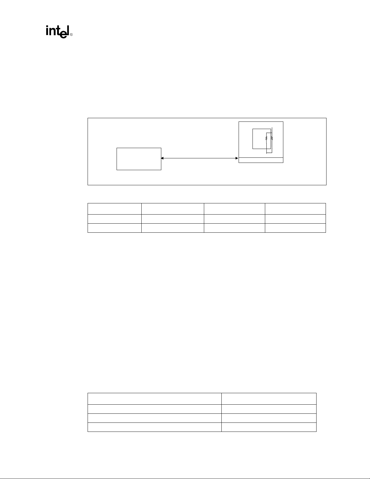
SC242 Processor Design Guidelines
3.2 Determine General Topology and Layout
Figure 3-1 provides segment descriptions and length recommendations for the investigated
topology shown. Segment lengths are defined at the pins of the devices or components. To ensure
processor signal integrity requirements, it is highly recommended that all system bus signal
segments to be referenced to the ground plane for the entire route.
Figure 3-1. Intel
®
Pentium® III Uni-Processor Configuration
Core
Vtt
Rtt
GMCH
L(1): Z0=60 W ±15%.
1.5" < L1 < 3.0" (100 MHz)
1.5" < L1 < 5.0" (100 MHz only)
Table 3-4. Segment Descriptions and Lengths for Figure 3-2
Segment Description Min length (inches) Max length (inches)
L1 (100 MHz) GMCH to SC242 1.50 3.00
L1 (100 MHz only) GMCH to SC242 1.50 5.00
1 - All AGTL+ bus signals should be referenced to the ground plane for the entire route.
NOTE:
3.3 Solution Space
•
AGTL+ signals should be routed with trace lengths within the range specified for L1 from the
processor pin to the chipset.
•
Use an intragroup AGTL+ spacing to line width to dielectric thickness ratio of at least 2:1:1
for microstrip geomety. If
AGTL+ routing could use 10 mil spacing, 5 mil traces, and a 5 mil prepreg between the signal
layer and the plane it references (assuming a 4-layer motherboard design).
•
The trace width is recommended to be 5 mils and not greater than 6 mils.
ε
= 4.5, this should limit coupling to 3.4%. For example, intragroup
r
SC242
1
Table 3-5 contains the trace width:space ratios assumed for this topology. The crosstalk cases
considered in this guideline involve three types: Intragroup AGTL+, Intergroup AGTL+, and
AGTL+ to non-AGTL+. Intragroup AGTL+ crosstalk involves interference between AGTL+
signals within the same group. Intergroup AGTL+ crosstalk involves interference from AGTL+
signals in a particular group to AGTL+ signals in a different group. An examp le of A GTL+ t o non AGTL+ crosstalk is when CMOS and AGTL+ signals interfere with each other.
Table 3-5. Trace Width:Space Guidelines
Crosstalk Type Trace Width:Space Ratios
Intragroup AGTL+ signals (same group AGTL+) 5:10 or 6:12
Intergroup AGTL+ signals (different group AGTL+) 5:15 or 6:18
AGTL+ to non-AGTL+ 5:20 or 6:24
Intel®810A3 Chipset Design Guide 3-3
Page 46

SC242 Processor Design Gui deline s
3.4 Minimizing Crosstalk
The following general rules will minimize the impact of crosstalk in the high speed AGTL+ bus
design:
The following general rules will minimize the impact of crosstalk in the high speed AGTL+ bus
design:
•
Maximize the space between traces. Maintain a minimum of 0.010” between traces wherever
possible. It may be necessary to use tighter spacings when routing between component pins.
•
Avoid parallelism between signals on adjacent layers.
•
Since AGTL+ is a low signal s w ing technology, it is important to isolate AGTL+ signals f rom
other signals by at least 0.025”. This will avoid coupling from signals that have larger voltage
swings, such as 5V PCI.
•
Select a board stack-up that minimizes the coupling between adjacent signals.
•
Route AGTL+ address, data and control signals in separate groups to minimize crosstalk
between groups. The Pentium
the address lines and corresponding control lines could be driven by a different agent than the
data lines and their corresponding control lines.
processor uses a split transaction bus. In a given clock cycle,
III
3.5 Motherboard Layout Rules for Non-AGTL+ (CMOS)
Signals
Non-AGTL+ (CMOS) Signals
Route these signals on any layer or any combination of layers.
Table 3-6. Routing Guidelines for Non-AGTL+ Signals
Signal Trace Width Spacing to Other Traces Trace Length
A20M# 5 mils 10 mils 1” to 9”
FERR# 5 mils 10 mils 1” to 9”
FLUSH# 5 mils 10 mils 1” to 9”
IERR# 5 mils 10 mils 1” to 9”
IGNNE# 5 mils 10 mils 1” to 9”
INIT# 5 mils 10 mils 1” to 9”
THERMTRIP# 5 mils 10 mils 1” to 9”
LINT[0] (INTR) 5 mils 10 mils 1” to 9”
LINT[1] (NMI) 5 mils 10 mils 1” to 9”
PWRGOOD 5 mils 10 mils 1” to 9”
SLP# 5 mils 10 mils 1” to 9”
PICD[1:0] 5 mils 10 mils 1” to 8”
PREQ# 5 mils 10 mils 1” to 9”
SMI 5 mils 10 mils 1” to 9”
STPCLK# 5 mils 10 mils 1” to 9”
3-4
Intel®810A3 Chipset Design Guide
Page 47

3.6 THRMDP and THRMDN
These traces (THRMDP and THRMDN) route the processor’s thermal diode connections. The
thermal diode operates at very low currents and may be susceptible to crosstalk. The traces should
be routed close together to reduce loop area and inductance. Refer to Figure 3-2.
Figure 3-2. Routing for THRMDP and THRMDN
Signal Y
1 -- Maximize (min - 20 mils)
THRMDP
THERMDN
1 -- Maximize (min - 20 mils)
Signal Z
SC242 Processor Design Guidelines
2 -- Minimize
Rule
Length Equalization route these traces parallel ±0.5”
Layer route both on the same layer
3.7 Additional Considerations
•
Distribute Vtt with a wide trace. A 0.050” minimum trace is recommended to minimize DC
losses. Route the Vtt trace to all components on the host bus. Be sure to include decoupling
capacitors. Guidelines for Vtt distribution and decoupling are contained in
AP-907: Pentium
•
The Vtt voltage should be 1.5V ±3% for static conditions, and 1.5V ±9% for transient
condition.
•
Place resistor divider pairs for V
is needed at the processor. V
decoupling capacitors. Guidelines for V
907: Pentium
Processor Power Distribution Guidelines, Order # 245085.
III
generation at the GMCH component. No V
REF
is generated locally on the processor. Be sure to include
REF
Processor Power Distribution Guidelines (Order # 245085).
III
REF
generation
REF
distribution and decoupling are contained in AP-
Intel®810A3 Chipset Design Guide 3-5
Page 48

SC242 Processor Design Gui deline s
3.8 Motherboard Frequency Select for SC242 Designs
Figure 3-3 shows the GMCH and processor straps for selecting the system bus frequency.
Figure 3-3. System Bus Frequency Selection Topology for SC242
220
3.3V
Ω
220
Ω
Processor
BSEL0 BSEL1
Ω
10 K
LMD29 LMD13
GMCH
10 K
10 K
14 MHz
REFCLK
Ω
REF
CK810
SEL0
Ω
SEL1
3.3V3.3V
8.2 K
Ω
3-6
Intel®810A3 Chipset Design Guide
Page 49

SC242 Processor Design Guidelines
3.9 S.E.C.C. 2 Grounding Retention Mechanism (GRM)
Intel is enabling a new S.E.P.P. (Single Edge Processor Package) style retention mechanism which
will provide a groundin g path for t he heatsink on processor s in the S.E.C .C. 2 (Sin gle Edge Co ntact
Cartridge) package. This solution is referred to as the S.E.C.C.2 Grounding Retention Mechanism
(GRM). OEMs who choose to utilize this new solution will need to add grounding pads on the
primary side of the motherboard which will inter face with the enabled GRM. If the mother board or
heat sink do not have the proper interfaces, then the GRM may not be utilized to its full ability , and/
or damage could occur to the motherboard.
The most notable interface requirement to accommodate the GRM is the addition of grounding
pads around two of the Retention Mechanism (RM) mounting holes within the existing RM keepout zone on the motherboard. The other interface is a contact area on the heat sink flanges. The
interface size and locations for the motherboard are discussed in detail further in this section .
The reference design GRM is asymmetric, and requires 0.159” mounting holes. To minimize the
impact to trace routing, only two ground pads are required. This makes it necessary to key the
GRM to prevent the ground clips from being installed on soldermask instead of the grounding
pads. This keying is accomplished by making the GRM asymmetric. The requirement for the
0.159” mounting holes is for the supported plastic fastener attachment mechanism.
3.9.1 Motherboard Interfaces
Figure 3-4. Hole Locations and Keep-out Zones for Support Components
Primary Side
1.270
0.806
0.231
∅
4x
0.300 Keepout
Secondary Side
NOTES:
1. Hole Location s and Keep-out Zones are from the motherboard surface to .100” above the motherboard
surface.)
2. The dashed lines represent the centerlines for the connector keying features.
0.232
0.375
0.175
4.706
4.881
5.256
1. All dimensions are in inches and all tolerances
±0.04, unless otherwise specified.
2. Dash lines represent control line for connector
key features when placed on planar.
3. Retention solution not to exceed height of 2.75"
off of primary side of planar and 0.150" off of
secondary side of planar.
4. Retention mechanism must stay within crosshatch area.
4x Thru Æ .159
1.038
+0.002
-0.001
Intel®810A3 Chipset Design Guide 3-7
Page 50

SC242 Processor Design Gui deline s
Figure 3-5. Detailed Drawing of Minimum Ground Pad Size and Location
0.364
0.182
Detail A
NOTE: DRAWING NOT TO SCALE
NOTE:
0.232
0.15
∅
+0.0
2
0.464
Notes:
1. All dimensions are in inches and all
tolerances are ±0.004, unless otherwise
specified.
2. Retention mechnasim must stay within
X-Hatch area.
3. Entire specified plating area must be plated
and grounded with a minum of eight VIAS.
Ground Pad Areas,
See Detail A
Heat Sink Area
It is not recommended to use the GRM without the minimum size ground pads in the correct
locations. If the GRM is used without the correct pads, then there is a high risk that the metal clip
that grounds to the motherboard will be t ouching the sold er mask on the top layer of the bo ard, and
possibly short out traces immediately beneath the solder mask, resulting in board failure. The
required thickness of the pad is less than 0.001” (using 1/2 oz copper).
3-8
Intel®810A3 Chipset Design Guide
Page 51

Layout and Routing
Guidelines
4
Page 52

This page is intentionally left blank
Page 53

Layout and Routing Guidelines
Layout and Routing Guidelines
This chapter describes motherboard layout and routing guidelines f or I ntel 810A3 Chipset
systems, except for the processor layout guidelines. For the PGA370 processor specific layout
guidelines, refer to Chapter 2, “PGA370 Pro cessor Design Guidelines”. For the SC242 processor
specific layout guidelines, refer to Chapter 3, “SC242 Processor Design Guidelines”. This chapter
does not discuss the functional aspects of any bus or the layout guidelines for an add-in device.
Note: If the guidelines listed in this document are not followed, it is very important that thorough
signal integrity and timing simulations are completed for each design. Even when the
guidelines are followed, critical signals are recommended to be simulated to ensure proper signal
integrity and flight time. Any deviation from these guidelines should be simulated.
4.1 General Recommendations
The trace impedance typically noted (i.e., 60Ω ±15%) is the “nominal” trace impedance for a 5 mil
wide trace (i.e., the impedance of the trace when not subjected to the fields created by changing
current in neighboring traces). When calculating flight times, it is important to consider the
minimum and maximum impedance of a trace based on the switching of neighboring tr aces. Using
wider spaces between the traces can minimize this trace-to-trace coupling. In addition, these wider
spaces reduce settling time.
4
Coupling between two traces is a function of the coup led length , the d istance sepa rating the traces ,
the signal edge rate, and the degree of mutual capacitance and inductance. To minimize the effects
of trace-to-trace coupling, the routing guidelines documented in this section should be followed.
Additionally, these routing guidelines are created using the stack-up (refer to Figure 4-1). I f this
stack-up is not used, simulations should be completed.
4.2 Nominal Board Stackup
The Intel® 810A3 chipset platform requires a board stackup yielding a target impedance of
60Ω±15% with a 5 mil nominal trace width. Figure 4-1 presents an example stackup to achieve
this. It is a 4-layer fabrication construction using 53% resin, FR4 material.
Intel®810A3 Chipset Design Guide 4-1
Page 54

Layout and Routing Guidelines
Figure 4-1. Nominal Board Stackup
Component Side Layer 1 (1/2 oz. cu)
4.5 mil Prepreg
Power Plane Layer 2 (1 oz. cu)
~48 mil Core
Ground Layer 3 (1 oz. cu)
4.5 mil Prepreg
Solder SIde Layer 4 (1/2 oz. cu)
4.3 Component Quadrant Layouts
62 mils
Total
Thickness
Figure 4-2. GMCH Quadrant Layout (topview)
Pin A1
System
Memory
System Bus
System
Memory
GMCH Top View
Hub
Interface
Display
Cache
Digital
Video
Out
4-2
System Bus
CRT Display
Intel®810A3 Chipset Design Guide
Page 55

Figure 4-3. ICH 241-uBGA Quadrant Layout (topview)
Layout and Routing Guidelines
Pin #1 Corner
AC'97,
SMBus
LPC
PCI
ICH
241 uBGA
Processor
Hub Interface
IDE
Intel®810A3 Chipset Design Guide 4-3
Page 56

Layout and Routing Guidelines
4.4 Intel 810A3 Chipset Component Placement
The assumptions for component placement are:
•
uATX Form Factor
•
4-Layer Motherboard
•
Single Sided Assembly
Figure 4-4. uATX Placement Example for PGA370 Processors
4-4
Intel®810A3 Chipset Design Guide
Page 57

Layout and Routing Guidelines
4.5 System Memory Layout Guidelines
4.5.1 System Memory Solution Space
Figure 4-5. System Memory Topologies
GMCH
Topology 1
Topology 2
Topology 3
A
B
10 ohm
10 ohm
A
A
D
C
DIMM0 DIMM1
F
G
Topology 4
Topology 5
A
A
D
E
T a ble 4-1. System Memory Routing
Trace Lengths (inches)
Trace (mils) A B C D E F G
Signal Top. Width Space Max Min Max Min Max Min Max Min Max Min Max Min Max
SCS[3:2]# Opt.1 5 10 8 3 5 1.5 2
Opt.2 5 10 8 2.2 5 1.5 1.8
Opt.3 5 10 8 1.6 5 1.15 1.5
SCS[1:0]# Opt.1 4 10 8 3 5 1.5 2
Opt.2 4 10 8 2.2 5 1.5 1.8
Opt.3 4 10 8 1.6 5 1.15 1.5
SMAA[7:4] 1 10 8 0.5 0.5 2
SMAB[7:4]# 2 10 8 0.5 0.5 2
SCKE[1:0] 3 10 8 1 2.5 0.4 1
SMD[63:0],
SDQM[7:0]
SCAS#,
SRAS#,
SWE#
SBS[1:0],
SMAA[11:8,
3:0]
NOTE:
35 7 13 0.41
35 7 13.5 0.41
35 7 12.5 0.41
It is recommended to add 10Ω series resistors to the MAA[7:4] and the MAB[7:4] lines as close as
possible to GMCH for signal integrity.
G
Intel®810A3 Chipset Design Guide 4-5
Page 58

Layout and Routing Guidelines
4.5.2 System Memory Routing Example
Figure 4-6. System Memory Routing Example
4-6
Intel®810A3 Chipset Design Guide
Page 59

4.5.3 System Memory Connectivity
Figure 4-7. System Memory Connectivity
System Memory Array: 2 DIMM Sockets
(Double-Sided Unbuffered Pinout w/o ECC)
SCS[3:2]#
SCS[1:0]#
SCKE0
SCKE1
SRAS#
GMCH
CK810E
ICH
SCAS#
SWE#
SBS[1:0]
SMAA[11:8, 3:0]
SMAA[7:4]
SMAB[7:4]#
SDQM[7:0]
SMD[63:0]
DIMM_CLK[3:0]
DIMM_CLK[7:4]
SMB_CLK
SMB_DATA
Layout and Routing Guidelines
Min (16 Mbit) 8 MB
Max (64 Mbit) 256 MB
Max (128 Mbit) 512 MB
DIMM 0 and 1
4.6 Display Cache Interface
Figure 4-8. Display Cache (Topology 1)
A
Intel®810A3 Chipset Design Guide 4-7
1Mx16
Page 60

Layout and Routing Guidelines
4.6.1 Display Cache Solution Space
T a ble 4-2. Display Cache Routing (Topology 1)
Signal Topology Width Spacing Min Max
LMD[31:0], LDQM[3:0] 1 5 7 1 5
Trace Length (inches)
NOTE:
Figure 4-9. Display Cache (Topology 2)
Trace (mils) A (inches)
B
T a ble 4-3. Display Cache Routing (Topology 2)
Signal Topology Width Spacing Min Max Min Max
LMA[11:0], LWE#, LCS#, LRAS#, LCAS# 2 5 7 1 3.75 0.75 1.25
Figure 4-10. Display Cache (Topology 3)
22 Ohms
DE
C
C
Trace (units=mils) B (inches) C (inches)
1Mx16
1Mx16
F
1Mx16
T a ble 4-4. Display Cache Routing (Topology 3)
Signal Topology Width Spacing Length Min Max Min Max
TCLK 3 5 7 0.5 1.5 2.5 0.75 1.25
4-8
F
Trace (units=mils) D (inches) E (inches) F (inches)
1Mx16
Intel®810A3 Chipset Design Guide
Page 61

Figure 4-11. Display Cache (Topology 4)
Layout and Routing Guidelines
OCLK
RCLK
Table 4-5. Display Cache Routing (Topology 4)
Signal Topology Width Spacing Length Min Max
OCLK 4 5 6 0.5 3.25 3.75
4.7 Hub Interface
The GMCH ball assignment and ICH ball assignment have been optimized to simplify hub
interface routing. It is recommended that the hub interface signals are routed directly from the
GMCH to the ICH on the top signal layer (refer to Figure 4-12). The hub interface has two signal
groups:
•
Data Signals: HL[10:0]
•
Strobe Signals: HL_STB, HL_STB# (differential strobe pair).
GH
33 Ohms
Trace (units=mils) G (inches) H (inches)
There are no pull-ups or pull-downs required on the hub interface. HL11 can be brought out to a
test point for NAND Tree testing.
Each signal should be routed such that the signal meets the guidelines documented for its signal
group.
Figure 4-12. Hub Interface Signal Routing Example
HL_STB
HL_STB#
ICH GMCH
HL[10:0]
3V66 3V66
CK810E
Intel®810A3 Chipset Design Guide 4-9
Page 62

Layout and Routing Guidelines
4.7.1 Data Signals
Hub interface data signals should be routed with a trace width of 5 mils and a trace spacing of
20 mils. These signals can be routed with a trace width of 5 mils and a trace spacing of 15 mils for
navigation around components or mounting holes. To break-out of the GMCH and the ICH, the
hub interface data signals can be routed with a trace width of 5 mils and a trace spacing of 5 mils.
The signals should be separated to a trace width of 5 mils and a trace spacing of 20 mils within 0.3”
of the GMCH/ICH components.
The maximum trace length for the hub interface data signals is 7”. These signals should each be
matched within ±0.1” of the HL_STB and HL_STB# signals.
4.7.2 Strobe Signals
Due to their differential nature, the hub interface strobe signals should be 5 mils wide and routed
20 mils apart. This strobe pair should be a minimum of 20 mils from any adjacent signals. The
maximum length for the strobe signals is 7” and the two strobes should be the same length.
Additionally, the trace length for each data signal should be matched to the trace length of the
strobes with ±0.1”.
4.7.3 HREF Generation/Distribution
There are two types of HREF generation. For a single hub interface circuit, the top 500 pF
capacitor and 56Ω resistor are not stuffed. The lower 56Ω resistor is replaced with 0Ω (short).
The lower 500 pF capacitor is replaced by a 0.1 uF capacitor.
HREF is the hub interface reference voltage. It is 0.5 * 1.8V = 0.9V ±2%. It can be generated
locally, or a single HREF divider can be used (as shown in Figure 4-13 and in Figure 4-14). The
resistors in the DC element should be equal in value and rated at 1% tolerance. The value of these
resistors must be chosen to ensure that the reference voltage tolerance is maintained over the entire
input leakage specification. The recommended range for the resis tor value is from minimum 100Ω
to maximum 1 KΩ. (300Ω is shown in the example.)
The single HREF divider should not be located more than 4" away from either the GMCH or the
ICH.
The reference voltage generated by a single HREF divider should be bypassed to ground at each
component with a 0.01 uF capacitor located close to the component HREF pin. If the reference
voltage is generated locally, the bypass capacitor needs to be close to the component HREF pin.
4-10
Intel®810A3 Chipset Design Guide
Page 63

Figure 4-13. Single Hub Interface Reference Divider Circuit
1.8V
Ω
GMCH
300
Layout and Routing Guidelines
ICH
HUBREF
0.01 uF
Ω
300
0.01 uF
0.1 uF
Figure 4-14. Locally Generated Hub Interface Reference Dividers
1.8V
300
300
Ω
Ω
0.01 uF
0.01 uF
GMCH
HUBREF
1.8V
HUBREF
300
Ω
300
Ω
ICH
HUBREF
4.7.4 Compensation
There are two options for the ICH hub interface compensation (HLCOMP). HLCOMP is used by
the ICH to adjust buffer characteristics to specific board characteristics. Refer to the Intel
82801AA (ICH) and Intel
®
82801AB (ICH0) I/O Controller Hub Datasheet for details on
compensation. It can be used as either Impedance Compensation (ZCOMP) or Resistive
Compensation (RCOMP). The guidelines are below:
•
RCOMP: Tie the HLCOMP pin to a 40Ω 1% or 2% pull-up resistor (to 1.8V) via a 10 mil
wide, 0.5” trace (targeted for a nominal trace impedance of 40Ω).
•
ZCOMP: The HLCOMP pin should be tied to a 10 mil trace that is AT LEAST 18” long. This
trace should be unterminated and care should be taken when routing the signal to avoid
crosstalk (15-20 mil separation between this signal and any adjacent sign als is recommended ).
This signal may not cross power plane splits.
The GMCH also has a hub interface compensation pin. This signal (HLCOMP) can be routed u sing
either the RCOMP method or ZCOMP method described for the ICH.
Intel®810A3 Chipset Design Guide 4-11
®
Page 64

Layout and Routing Guidelines
4.8 Ultra ATA/66
4.8.1 IDE Routing Guidelines
This section contains guidelines for connecting and routing the ICH IDE interface. The ICH has
two independent IDE channels. This section provides guidelines for IDE connector cabling and
motherboard design, including component and resistor placement, and signal termination for both
IDE channels. The ICH0 and the ICH has integrated the series terminating resistors that have been
typically required on the IDE data and control signals running to the two ATA connectors.
The IDE interface can be routed with 5 mil traces on 5 mil spaces and should be less than 8 inches
long (from ICH to IDE connector). Additionally, the shortest IDE signal (on a given IDE channel)
must be less than 1” shorter than the longest IDE signal (on the channel).
Cabling
•
Length of Cable: Each IDE cable should be equal to or less than 18 inches.
•
Capacitance: Less than 30 pF.
•
Placement: A maximum of 6 inches between drive connectors on the cable. If a single drive is
placed on the cable it should be placed at the end of the cable. If a second dr ive is placed on the
same cable it should be placed on the next closest connector to the end of the cable (6” away
from the end of the cable).
•
Grounding: Provide a direct low impedance chassis path between the motherboard ground
and hard disk drives.
•
UltraATA/66: Ultra ATA/66 requires the use of an 80 conductor cable
•
ICH Placement: The ICH should be placed within 8” of the ATA connector.
•
PC99 Requirement: Support Cable Select for master-slave configuration is a system design
requirement for Microsoft* PC99. The CSEL signal needs to be pulled down at the host side
by using a 470Ω pull-down resistor for each ATA connector.
Figure 4-15. IDE Min/Max Routing and Cable Lengths
8 in. Max
Traces
ICH
IDE
Connector
A new IDE cable is required for Ultra ATA/66. This cable is an 80 conductor cable; however, the
40 pin connectors do not change. The wires in the cable alternate: ground, signal, ground, signal,
ground, signal, ground , etc. All the ground wires are t ied together on the cable (and t hey are t ied to
4-12
10-18 in.
4-6 in.5-12 in.
Intel®810A3 Chipset Design Guide
Page 65

the ground on the motherboard through the ground pins in the 40 pin connector). This cable
conforms to the Small Form Factor Specification SFF-8049. This specification can be obtained
from the Small Form Factor Committee.
Figure 4-16. Ultra ATA/66 Cable
Layout and Routing Guidelines
IDE Connector
Black wires are ground
Grey wires are signals
Motherboard
•
ICH Placement: The ICH should be placed within 8” of the ATA connector(s). There are no
minimum length requirements for this spacing.
•
Capacitance: The capacitance of each pin of the IDE connector on the host should be below
25 pF when the cables are disconnected from the host.
•
Series Termination: There is no need for series termination resistors on the data and control
signals since there is series termination integrated into these signal lines on the ICH.
— A 1 KΩ pullup to 5V is required on PIORDY and SIORDY.
— A 470Ω pulldown is required on pin 28 of each connector.
— A 5.6 KΩ pulldown i s required on P DREQ and SDREQ.
— Support Cable Select (CSEL) is a PC99 requirement. The state of the cable select pin
determines the master/slave configuration of the hard drive at the end of the cable.
— Primary IDE connector uses IRQ14 and the secondary IDE connector uses IRQ15.
— IRQ14 and IRQ15 each need an 8.2KΩ pull-up resistor to VCC.
— Due to the elimination of the ISA bus from the ICH, PCI_RST# should be connected to
pin 1 of the IDE connectors as the IDE reset signal. Due to high loading, the PCI_RST#
signal should be buffered.
— There is no internal pul l up or down on P DD7 or SDD7 of t he ICH. Devices s hall not have
a pull-up resistor on DD7. It is recommen ded that a hos t h ave a 10KΩ pull-down resistor
on PDD7 and SDD7 to allow the host to recognize the absence of a device at power-up (as
required by the ATA-4 specification).
— If no IDE is implemented with the ICH, the input signals (xDREQ and xIORDY) can be
grounded and the output signals left as no connects.
Intel®810A3 Chipset Design Guide 4-13
Page 66

Layout and Routing Guidelines
Figure 4-17. Resistor Schematic for Primary IDE Connectors
PCIRST_BUF#*
PDD[15:8]
PDD[7]
PDD[6:0]
PDA[2:0]
PDCS1#
PDCS3#
PDIOR#
PDIOW#
PDDREQ
PIORDY
IRQ14
PDDACK#
ICH
*Due to high loading, PCIRST# must be buffered.
1k
ohm
5V
8.2k
ohm
5V
5.6k
ohm
10k
ohm
Figure 4-18. Resistor Schematic for Secondary IDE Connectors
22 - 47 ohm
470 ohm
N.C.
Reset#
Primary IDE Connector
CSEL
Pin32
PCIRST_BUF#*
SDD[15:8]
SDD[7]
SDD[6:0]
SDA[2:0]
SDCS1#
SDCS3#
SDIOR#
SDIOW#
SDDREQ
SIORDY
IRQ15
SDDACK#
ICH
*Due to high loading, PCIRST# must be buffered.
1k
ohm
5V
8.2k
ohm
5V
5.6k
ohm
10k
ohm
22 - 47 ohm
470 ohm
N.C.
Reset#
Secondary IDE Connector
CSEL
Pin32
4-14
Intel®810A3 Chipset Design Guide
Page 67

4.8.2 Ultra ATA/66 Detection
The 82801AA ICH supports Ultra ATA/66 devices. The ATA/66 cable is an 80-conductor cable;
however the 40 pin connectors used on motherboards for 40-conductor cables do not change as a
result of this new cable. The wires in the cable alternate: ground, signal, ground, signal, ground,
signal, ground, etc. All the ground wires are tied together at the connectors on the cable (and they
are tied to the ground on the motherboard through the ground pins in the 40 pin connector). This
cable conforms to the Small Form Factor Specification SFF-8049. This specification can be
obtained from the Small Form Factor Committee.
T o determine if ATA/66 mode can be enabled, the Intel
system BIOS to attempt to determine the cable type used in the system. The BIOS does this in one
of two ways:
•
Host Side Detection
•
Device Side Detection
If the BIOS detects an 80-conductor cable, it may use any Ultra DMA mode up to the highest
transfer mode supported by both the ICH and the IDE device. Otherwise, the BIOS can only enable
modes that do not require an 80-conductor cable (example: Ultra ATA/33 Mode).
Layout and Routing Guidelines
®
810A3 chipset using th e IC H requ i res t he
After determining the Ultra DMA mode to be used, the BIOS will configure the Intel
chipset hardware and software to match the selected mode.
4.8.2.1 Ultra ATA/66 Motherboard Guidelines
The Intel® 810A3 chipset can use two methods to detect the cable type. Each mode requires a
different motherboard layout.
Host-Side Detection—BIOS Detects Cable Type Using GPIOs
Host side detection requires the use of two GPI pins (1 per IDE controller). The proper way to
connect the PDIAG#/CBLID# signal of the IDE connector to the host is shown in Figure 4-19. All
Ultra ATA/66 devices have a 10 KΩ pull-up resistor to 5 volts. Most of the GPIO pins on the ICH
and all GPIs on FWH Flash BIOS are not 5 volt tolerant. This requires a resistor divider so that 5
volts will not be driven to the ICH or FWH Flash BIOS pins. The proper value of the series resistor
is 15 KΩ (as shown on Figure 4-19). This creates a 10 KΩ/15 KΩ resistor divider and will produce
approximately 3 volts for a logic high.
This mechanism allows the host, after diagnostics, to sample PDIAG#/CBLID#. If PDIAG#/
CBLIB# is high, then there is 40-conductor cabl e in the system and ATA modes 3 and 4 should not
be enabled. If PDIAG#/CBLID# is low, then there is an 80-conductor cable in the system.
®
810A3
Intel®810A3 Chipset Design Guide 4-15
Page 68

Layout and Routing Guidelines
Figure 4-19. Host-Side IDE Cable Detection
To Secondary
IDE Connector
GPIO
ICH
GPIO
15K
To Secondary
IDE Connector
GPIO
40-Conductor
Cable
80-Conductor
IDE Cable
IDE Drive
5V
10K
PDIAG
IDE Drive
5V
10K
ICH
GPIO
15K
Open
PDIAG
Device-Side Detection—BIOS Queries IDE Drive for Cable Type
Device side detection requires only a 0.047 uF capacitor on the motherboard as shown in
Figure 4-20. This mechanism creates a resistor-capacitor (RC) time con stant. The AT A mode 3 or 4
drive will drive PDIAG#/CBLID# low and then release it (pulled up through a 10 KΩ resistor).
The drive will sample the PDIAG# signal after releasing it. In an 80-conductor cable,
PDIAG#/CBLID# is not connected through and therefore the capacitor has no effect. In a
40-conductor cable, PDIAG#/CBLID# is co nnected tho ugh to th e d rive. Theref ore, the signal rises
more slowly. The drive can detect the difference in rise times and it reports the cable type to the
BIOS when it sends the IDENTIFY_DEVICE packet during system boot as described in the
ATA/66 specification.
4-16
Intel®810A3 Chipset Design Guide
Page 69

Figure 4-20. Host-Side IDE Cable Detection
Layout and Routing Guidelines
IDE D rive
10K
IDE D rive
10K
IC H
IC H
0.047uF
0.047uF
40-Conductor
Cable
80-Conductor
IDE Cable
5V
PDIAG
5V
PDIAG
Open
Layout for Both Host-Side and Drive-Side Cable Detection
It is possible to layout for both Host-Side and Drive-Side cable detection and decide the method to
be used during assembly. Figure 4-21 shows the layout that allows for both host-side and drive-side
detection.
•
For Host-Side Detection
— R1 is a 0Ω resistor
— R2 is a 15 KΩ resistor
— C1 is not stuffed
•
For Drive-Side Detection
— R1 is not stuffed
— R2 is not stuffed
— C1 is a 0.047 uF capacitor
Figure 4-21. Host-Side IDE Cable Detection
ICH
R2
R1
C1
Intel®810A3 Chipset Design Guide 4-17
Page 70

Layout and Routing Guidelines
4.9 AC’97
The ICH implements an AC’97 2.1 compliant digital controller. Any codec attached to the ICH
AC-link should be AC’97 2.1 compliant as well. Contact your preferred codec vendor for
information on AC’97 2.1 compliant products. The AC’97 2.1 specification is on the Intel website:
http://developer.intel.com/pc-supp/platform/ac97/index.htm
The ICH supports the following combinations of codecs:
Table 4-6. AC’97 Configuration Combinations
Primary Secondary
Audio (AC) None
Modem (MC) None
Audio (AC) Modem (MC)
Audio/Modem (AMC) None
As shown in Table 4-6, the ICH does not support two codecs of the same type on the link. For
example, if an AMC is on the link, it must be the only codec. If an AC is on the link, another AC
cannot be present.
4.9.1 Audio/Modem Riser Card (AMR)
Intel is developing a common connector specification known as the Audio/Modem Riser (AMR).
This specification defines a mechanism for allowing OEM plug-in card options. The AMR
specification is available on the Intel developer website:
http://developer.intel.com/pc-supp/platform/ac97/index.htm
The AMR specification provides a mechanism for AC’97 codecs to be on a riser card. This is
important for modem codecs as it helps ease international certification of the modem.
4-18
Intel®810A3 Chipset Design Guide
Page 71

4.9.2 AC’97 Routing
To ensure maximum performance from the codec, proper component placement and routing
techniques are required. These techniques include properly isolating the codec, associated audio
circuitry, analog power supplies, and analog ground planes from the rest of the motherboard. This
includes plane splits and proper routing of signals not associated with the audio section. Contact
your vendor for device specific recommendations.
Following are the basic recommendations:
•
Special consideration must be given for the ground return paths for the analog signals. If
isolated ground planes are used, pin B2 on the AMR connector should be used as an isolated
ground pin and should be connected to an isolated ground plane to reduce noise in the analog
circuits. The AMR designer and motherboard designer should joi ntl y address any EMI issues
when implementing isolated grounds.
•
Digital signals routed in the vicinity of the analog audio signals must no t cross the power plane
split lines. Analog and digital signals should be located as far as possible from each other.
•
Partition the board with all analog components grouped together in one area and all digital
components in the other.
•
Separate analog and digital ground planes should be provided, with the digital components
over the digital ground plane, and the analog components, including the analog power
regulators, over the analog ground plane. The split between the planes must be a minimum of
0.05” wide.
•
Keep digital signal traces, especially the clock, as far way from analog input and voltage
reference pins as poss ible.
•
Do not completely isolate the analog/audio ground plane from the rest of the board ground
plane. There should be a single point (¼” to ½ ” wide) where the analog/isolated grou nd plan e
connects to the main ground plane. The split between the planes must be a minimum of 0.05”
wide.
•
Any signals entering or leaving the analog area must cross the ground split in the area where
the analog ground is attached to the main motherboard ground (i.e., there should not be any
signals crossing the split/gap between the ground planes). Doing so will cause a ground loop.
This will greatly increase EMI emissions and degrade analog and digital signal quality.
•
Analog power and signal traces should be routed over the analog ground plane.
•
Digital power and signal traces should be routed over the digital ground plane.
•
Bypassing and decoupling capacitors should be close to the IC pins, or positioned for the
shortest connections to pins, with wide traces to reduce impedance.
•
All resistors in the signal path or on the voltage reference should be metal film. Carbon
resistors can be used for DC voltages and the power supply path where voltage coefficient,
temperature coefficient or noise are not a factor.
•
Regions between analog signal traces should be filled with copper, which should be
electrically attached to the analog ground plane. Regions between digital signal traces should
be filled with copper, which should be electrically attached to the digital ground plane.
•
Locate the crystal or oscillator close to the codec.
•
Figure 4-22 and Figure 4-23 show the motherboard trace lengths for an ATX form factor with
a codec on the motherboard and an AMR connector. Two routing metho ds are prov ided for the
AC’97 interface: the tee topology and the daisy-chain topology. The AC’97 link signals can be
routed using 5 mil traces with 5 mil space between the traces. NLX routing recommendations
will be provided in a future revision of this document.
Layout and Routing Guidelines
Intel®810A3 Chipset Design Guide 4-19
Page 72

Layout and Routing Guidelines
Figure 4-22. Tee Topology AC'97 Trace Length Requirements for ATX
4" Max
Codec
ICH
2" Max 3" Max
A
M
R
Figure 4-23. Daisy-Chain Topology AC'97 Trace Length Requirements for ATX
ICH Codec
5" Max 3" Max
A
M
R
4-20
Clocking is provided from the primary codec on the link via BITCLK, and is derived from a
24.576 MHz crystal or oscillator. Refer to the primary codec vendor for crystal or oscillator
requirements. BITCLK is a 12.288 MHz clock driven by the primary codec to the digital contro ller
(ICH), and any other codec present. That clock is used as the timebase for latching and driving
data.
The ICH supports wake on ring from S1-S4 via the AC’97 link. The codec asserts SDATAIN to
wake the system. To provide wake capability and/or caller ID, standby power must be provided to
the modem codec.
If no codec is attached to the link, internal pulldowns will prevent the inputs from floating;
therefore, external resistors are not required.
Intel®810A3 Chipset Design Guide
Page 73

4.9.3 Motherboard Implementation
The following design considerations are provided for the implementation o f an ICH platfor m using
AC’97. These design guidelines have been developed to ensure maximum flexibility for board
designers while reducing the risk o f boar d rela te d issues . These recommendations do not represent
the only implementation or a complete checklist, but provides recommendations based on the ICH
platform.
•
Codec Implementation
— The motherboard can implement any valid combination o f codecs on the motherbo ard and
on the riser. For ease of homologation, it is recommended that a modem codec be
implemented on the AMR module; however, nothing precludes a modem codec on the
motherboard.
— Only one primary codec can be p resent on the link. A maximum of two pr esent codecs can
be supported in an ICH platform.
— If the motherboard implements an active primary codec on the motherboard and provides
an AMR connector, it must tie PRI_DN# to ground.
— The PRI_DN# pin is provided to indicate a primary codec is present on the motherboard.
Therefore, the AMR module and/or codec must provide a means to prevent contention
when this signal is asserted by the motherboard, without software intervention.
— Components such as FET switches, buffers, or logic states should not be implemented on
the AC-link signals, except for AC_RST#. Doing this will potentially interfere with
timing margins and signal integrity.
— If the motherboard requires that an AMR mod ule override a primary codec down , a means
of preventing contention on the AC-link must be provided for the onboard codec.
Layout and Routing Guidelines
— The ICH supports Wake On Ring from S1-S4 states via the AC’97 link. The codec asserts
SDATAIN to wake the system. To provide wake capabilit y and/or caller ID, standby
power must be provided to the modem codec. If no codec is attached to the link, internal
pulldowns prevent the inputs from floating; therefore, external resistors are not required.
The ICH does not wake from the S5 state via the AC’97 lin k.
— The SDATAIN[0:1] pins should not be left in a floating st ate if the pins are not con nected
and the AC-link is active—they should be pulled to ground through a weak
(approximately 10 KΩ) pull-down resistor. If the AC-link is disabled (by setting the shutoff bit to 1), then the ICH’s internal pull-down resistors are enabled, and thus there is no
need for external pull-down resistors. However, if the AC-link is to be active, then there
should be pull-down resistors on any SDATAIN signal that has the potential of not being
connected to a codec. For example, if a dedicated audio codec is on the moth erbo ard, an d
cannot be disabled via a hardware jumper or stuffing option, then its SDATAIN signal
does not need a pull-down resistor. If, however, the SDATAIN signal has no codec
connected, or is connected to an AMR slot, or is connected to an onboard codec that can
be hardware disabled, then the signal should have an external pull-down resistor to
ground.
— In a lightly loaded system (e.g., single codec down), AC'97 signal integrity analysis
should be evaluated to confirm that the signal quality on the link is acceptable by the
codec used in the design. A series resis tor at the driver and /or a cap acitor at the codec can
be implemented to compensate for any signal integrity issues. The values used are design
dependent and should be verified for correct timings. The IC H A C-link ou t put buffers are
designed to meet the AC'97 2.1 specification with the specified load of 5.
Intel®810A3 Chipset Design Guide 4-21
Page 74

Layout and Routing Guidelines
•
AMR Slot Special Connections
— AUDIO_MUTE#: No connect on the motherboard.
— AUDIO_PWRDN: No connect on the motherboard. Codecs on the AMR card should
implement a powerdown pin, per the AC’97 2.1 specification, to control the amplifier.
— MONO_PHONE: Connect top onboard audio codec if supported.
— MONO_OUT/PC_BEEP: Connect to SPKR output from the ICH, or MONO_OUT from
onboard codec.
— PRIMARY_DN#: See discussion above.
— +5VDUAL/+5VSB: Connect to VCC5 core on the motherboard, unless adequate power
supply is available. An AMR card using this standby/dual supply should not prevent basic
operation if this pin is connected to core power.
— S/P-DIF_IN: Connect to ground on the motherboard.
— AC_SDATAIN[3:2]: No connect on the motherboard. The ICH supports a maximum of
two codecs, which should be attached to SDATAIN[1:0].
— AC97_MSTRCLK: Connect to ground on the motherboard.
•
The ICH provides internal weak pulldowns. Therefore, the motherboard does not need to
provide discrete pulldown resistors.
•
PC_BEEP should be routed through the audio codec. Care should be taken to avoid the
introduction of a pop when powering the mixer up or down.
4.10 USB
The following are general guidelines for the USB interface:
•
Unused USB ports should be terminated with 15 KΩ pulldown resistors on both P+/P - da ta
lines.
•
15Ω series resistors should be placed as close as possible to the ICH (<1 inch). These series
resistors are there for source termination of the reflected signal.
•
47 pF caps must be placed as close to the ICH as possible, and on the ICH side of the series
resistors on the USB data lines (P0±, P1±). These caps are for signal quality (rise/fall time) and
to help minimize EMI radiation.
•
15 KΩ ±5% pulldown resistors should be placed on the USB side of th e series res istors on the
USB data lines (P0±, P1±), and are for signal termination required by the USB specification.
The length of the stub should be as short as possible.
•
The trace impedance for the P0±, P1±- signals should be 45Ω (to ground) for each USB signal
P+ or P-. This may be achieved with 9 mil wide traces on the motherboard based on the
stackup recommended in Figure4-1. The impedance is 90Ω between the differential signal
pairs P+ and P- to match the 90Ω USB twisted pair cable impedance. Note that the twisted
pair characteristic impedance of 90Ω is the series impedance of both wires, resulting in an
individual wire presenting a 45Ω impedance. The trace impedance can be controlled by
carefully selecting the trace width, trace distance from power or ground planes, and physical
proximity of nearby traces.
•
USB data lines should be routed as ‘critical signals’ (i.e., hand routing preferred). The P+/Psignal pair should be routed together and not parallel with other signal traces to minimize
crosstalk. Doubling the space from the P+/P- signal pair to adjacent signal traces will help to
prevent crosstalk. The P+/P- signal traces should also be the same length. This minimizes the
effect of common mode current on EMI.
•
47 pF capacitors should be placed as close as possible to the USB connectors to help minim ize
EMI radiation.
4-22
Intel®810A3 Chipset Design Guide
Page 75
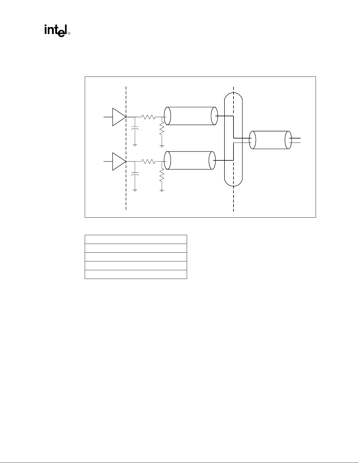
Figure 4-24 illustrates the recommended USB schematic.
Figure 4-24. USB Data Signals
Layout and Routing Guidelines
Motherboard Trace
45 ohm
15k
Motherboard Trace
45 ohm
15k
P+
P-
Driver
Driver
15 ohm
< 1"
47 pf
15 ohm
< 1"
47 pf
ICH0/ICH
Table 4-7. Recommended USB Trace Characteristics
Impedance ‘Z0’ = 45.4
Line Delay = 160.2 ps
Capacitance = 3.5 pF
Inductance = 7.3 nH
Res @ 20° C = 53.9m
Ω
Ω
90 ohm
USB Connector
USB Twisted Pair CableTransmission Line
4.11 IOAPIC (I/O Advanced Programmable Interrupt
Controller)
Systems that do not use the ICH I/O APIC should follow these recommendations:
On the ICH:
•
Tie PICCLK directly to ground
•
Tie PICD0, PICD1 directly to ground
On the processor:
•
PICCLK must be connected from the clock generator to the PICCLK pin on the processor
•
Tie PICD0 to VCC
•
Tie PICD1 to VCC
Note: If not using IOAPIC, turn off APIC clocks to ICH through I
Intel®810A3 Chipset Design Guide 4-23
through a 150Ω resistor
CMOS
through a 150Ω resistor
CMOS
2
C.
Page 76

Layout and Routing Guidelines
4.12 PCI
The ICH provides a PCI Bus interface that is compliant with the PCI Local Bus Specification
Revision 2.2. The implementation is optimized for high-performance data streamin g when the ICH
is acting as either the target or the initiator on the PCI bus. For more information on the PCI Bus
interface, please refer to the PCI Local Bus Specification Revision 2.2.
The ICH supports 6 PCI Bus masters (excluding ICH), by providing 6
REQ#/GNT# pairs. In addition, the ICH supports 2 PC/PCI REQ#/GNT# pairs, one of which is
multiplexed with a PCI REQ#/GNT# pair.
The ICH, based on simulations done by Intel, it is recommended that four is the maximum number
of PCI slots that should be connected to the ICH. This limit is due to timing and loading
considerations established during simulations. If a system designer wants to have 5 PCI slots
connected to the ICH, then it is recommended that they do simulations to verify proper design.
Figure 4-25. PCI Bus Layout Example for 4 PCI Connectors
ICH
4.13 RTC
The ICH contains a real time clock (RTC) with 256 bytes of battery backed SRAM. This internal
RTC module provides two key functions: a) keeping date and time, b) storing system data in its
RAM when the system is powered down.
This section will present the recommended hookup for the RTC circuit for the ICH. This circuit is
not the same as the circuit used for the PIIX4.
4.13.1 RTC Crystal
The ICH RTC module requires an external oscillating source of 32.768 KHz connected on the
RTC X1 and R TC X2 pins. Figure 4-26 represents the external circuitry that comprises the oscillator
of the ICH RTC.
4-24
Intel®810A3 Chipset Design Guide
Page 77

Figure 4-26. External Circuitry for the ICH RTC
Layout and Routing Guidelines
3.3V
VCCSUS
1 k
Ω
1 k
Vbatt
Note: Capacitor C2 and C3 values are crystal-dependent.
NOTES:
1. The exact capacitor value should be based on the crystal vendor’s recommendations.
2. VccRTC: Power for RTC Well.
3. RTCX2: Crystal Input 2 – Connected to the 32.768 KHz crystal.
4. RTCX1: C rystal Input 1 – Connected to the 32.768 KHz crystal.
5. VBIAS: RTC BIAS Voltage – This pin is used to provide a reference voltage, and this DC voltage sets a
current which is mirrored throughout the oscillator and buffer circuitry.
6. Vss : Ground.
Ω
C1
0.047 uF
1
µ
32768 Hz
Xtal
F
C3
18 pF
C2
18 pF
R1
10 M
R2
10 M
VCCRTC
RTCX2
Ω
RTCX1
Ω
VBIAS
VSSRTC
4.13.2 External Capacitors
T o maintain the R TC accuracy, the external capacitor C1 should be set to 0.047 uF, and the external
capacitor values (C2 and C3) should be chosen to provide the manufacturer’s specified load
capacitance (Cload) for the crystal when combined with the parasitic capacitance of the trace,
socket (if used), and package. The following equation can be used to choose the external
capacitance values (C2 and C3):
Cload = (C2*C3)/(C2+C3) + Cp arasit ic
C3 can be chosen such that C3 > C2; then, C2 can be trimmed to obtain the 32.768 KHz.
Intel®810A3 Chipset Design Guide 4-25
Page 78

Layout and Routing Guidelines
4.13.3 RTC Layout Considerations
•
Keep the XTAL lead lengths as short as possible; around 1 inch is sufficient.
•
Minimize the capacitance between RTCX1and RTCX2 in the routing.
•
Put a ground plane under the XTAL components.
•
Do not route any switching signals under the external components (unless on the other side of
the board).
•
The oscillator VCC should be clean; use a filter (e.g., an RC lowpass) or a ferrite inductor.
•
Keep high speed switching signals (e.g., PCI signals) away from VCCRTC, RTCX1, RTCX2
and VBIAS.
4.13.4 RTC External Battery Connection
The RTC requires an external battery connection to maintain its functionality and its RAM while
the ICH is not powered by the system.
Example batteries are: Duracell* 2032, 2025, or 2016 (or equivalent), which can give many years
of operation. Batteries are rated by storage capacity. The battery life can be calculated by dividing
the capacity by the average current required. For example, if the battery storage capacity is 170 mA
per hour (assumed usable) and the aver age cu rrent requ ir ed is 3 uA, the battery life will be at least:
170,000 uAhr / 3 uA = 56,666 h = 6 .4 yea rs
The voltage of the battery can affect the RTC accuracy. In general, when the battery voltage
decays, the RTC accuracy also decreases. High accuracy can be obtained when the RTC voltage is
in the range of 3.0V to 3.3V.
The battery must be connected to the ICH via an isolation diode circuit. The diode circuit allows
the ICH RTC well to be powered by the b attery when th e system po wer is no t availabl e, but by the
system power when it is available. To do this, the diodes are set to be reverse-biased when the
system power is not available. Figure 4-27 is an example of a diode circuitry that can be used.
Figure 4-27. A Diode Circuit to Connect RTC External Battery
VCC3_3SBY
1K
1.0uF
VccRTC
4-26
A standby power supply should be used to provide continuous power to the RTC when available,
which will significantly increase the RTC battery life and thereby the RTC accuracy.
Intel®810A3 Chipset Design Guide
Page 79

4.13.5 RTC External RTCRESET Circuit
The ICH RTC requires some additional external circuitry. The RTCRESET (R TC Well Test) signal
is used to reset the RTC Well. The external capacitor (2.2 uF) and the external resistor (8.2 KΩ)
between RTCRESET and the RTC battery (Vbat) were selected to create a RC time delay, such that
RTCRESET goes high some time after the battery voltage is valid. The RC time delay should be in
the range of 10–20 ms. When RTCRESET is asserted bit 2 (RTC_PWR_STS) in the
GEN_PMCON_3 (General PM Configuration 3) register is set to 1, and remains set until software
clears it. As a result, when the system boots, BIOS knows that the RTC battery has been removed.
Figure 4-28. RTCRESET External Circuit for the ICH RTC
Layout and Routing Guidelines
Diode/
Battery
Circuit
1 K
+
8.2 K
VCC3_3SBY
Ω
VCCRTC
1.0 µF
Ω
RTCRESET
2.2 µF
This RTCRESET circuit is combined with the diode circuit (Figure 4-27) which allows the RTC
well to be powered by the battery when the system power is not available. Figure 4-28 is an
example of this circuitry that is used, in conjunction with the external diode circuit.
4.13.6 VBIAS DC Voltage and Noise Measurements
•
Steady state VBIAS will be a DC voltage of about 0.38V ±.06V.
•
VBIAS will be “kicked” when the battery is inserted to about 0.7–1.0V; it will come back to its
DC value within a few ms.
•
Noise on VBIAS must be kept to a minimum (200 mV or less).
•
VBIAS is very sensitive and can not be directly probed; it can be probed through a 0.01 uF
capacitor.
•
Excess noise on VBIAS can cause the ICH internal oscillator to misbehave or even stop
completely.
•
To minimize noise of VBIAS it is necessary to implement the routing guidelines described
above and the required external RTC circuitry as described in the Intel
®
Intel
82801AB (ICH0) I/O Controller Hub Datasheet.
Intel®810A3 Chipset Design Guide 4-27
®
82801AA (ICH) and
Page 80

Layout and Routing Guidelines
4.14 Processor PLL Filter Recommendation
4.14.1 Processor PLL Filter Recommendation
All Intel® Celeron™ processors have internal PLL clock generators that are analog and require
quiet power supplies to minimize jitter.
4.14.2 Topology
The general desired topology is shown in Figure 4-29. Not shown are parasitic routing and local
decoupling capacitors. Excluded from the external circuitry are parasitics associated with each
component.
Figure 4-29. Filter Topology
VCC
CORE
RL
PLL1
4.14.3 Filter Specification
The function of the filter is to protect the PLL from external noise through low-pass attenuation. In
general, the low-pass description forms an adequate description for the filter.
The low-pass specification, with input at VCC
follows:
< 0.2 dB gain in pass band
< 0.5 dB attenuation in pass band (see DC drop in next set of requirements)
> 34 dB attenuation from 1 MHz to 66 MHz
> 28 dB attenuation from 66 MHz to core frequency
The filter specification is graphically shown in Figure 4-30.
C
PLL2
and output measured across the capacitor, is as
CORE
PLL
VSS = 0V
370-Pin
Socket
4-28
Intel®810A3 Chipset Design Guide
Page 81

Figure 4-30. Filter Specification
0.2dB
0dB
x dB
-28dB
-34dB
Layout and Routing Guidelines
1HzDC
passband
x = 20.log[(Vcc-60mV)/Vcc]
NOTES:
1. Diagram not to scale.
2. No spec ification for frequencies beyond fcore.
3. fpeak, if it exists, it should be less than 0.05 MHz.
1 MHz 66 MHz
high frequency
band
fcorefpeak
Other requirements:
•
Filter should support DC current > 30 mA.
•
Shielded type inductor to minimize magnetic pickup.
•
DC voltage drop from VCC to PLL1 should be < 60mV, which in practice implies ser ies
R < 2 Ω; also means pass band (from DC to 1Hz) attenuation < 0.5dB for
VCC = 1.1V, and < 0.35dB for VCC = 1.5V.
Intel®810A3 Chipset Design Guide 4-29
Page 82

Layout and Routing Guidelines
4.14.4 Recommendation for Intel Platforms
The following tables are examples of components that meet Intel’s recommendations, when
configured in the topology presented in Figure 4-29.
Table 4-8. Inductor
Part Number Value Tol SRF Rate d I DCR
TDK MLF2012A4R7KT 4.7 uH 10% 35 MHz 30 mA
Murata LQG21N4R7K00T1 4.7 uH 10% 47 MHz 30 mA
Murata LQG21C4R7N00 4.7 uH 30% 35 MHz 30 mA
Table 4-9. Capacitor
Part Number Value Tolerance ESL ESR
Kemet T495D336M016AS 3 3 uF 20% 2.5 nH
AVX TPSD336M020S0200 33 uF 20% TBD
0.56Ω (1W max)
0.7Ω (±50%)
0.3Ω max
Ω
0.225
Ω
0.2
Table 4-10. Resistor
Value Tolerance Po wer Note
Ω
1
10% 1/16 W
To satisfy damping requirements, total series resistance in the filter (from V
the capacitor) must be at least 0.35Ω. This resistor can be in the form of a discrete component, or
routing, or both. For examp le, if th e picked in ductor has a minimu m DCR o f 0.25Ω, then a routing
resistance of at least 0.10Ω is required. Be careful not to exceed the maximum resistance rule
(2Ω). For example, if using discrete R1, the maximum DCR of the L should be less than
2.0 - 1.1 = 0.9Ω, which precludes using some inductors.
Other routing requirements:
•
C should be close to PLL1 and PLL2 pins, < 0.1Ω per route. These routes do not count
towards the minimum damping R requirement.
•
PLL2 route should be parallel and next to PLL1 route (minimize loop area).
•
L should be close to C; any routing resistance should be inserted between V
•
Any discrete R should be inserted between V
Figure 4-31. Using Discrete R
VCC
CORE
R
Discrete Resistor
Resistor may be implemented with trace resistance, in which
discrete R is not needed
CC
to the top plate of
CORE
CC
and L.
CORE
CC
and L.
CORE
L
C
<0.1 ohm route
PLL1
370-Pin
Socket
4-30
<0.1 ohm route
PLL2
Intel®810A3 Chipset Design Guide
Page 83

Figure 4-32. No Discrete R
VCC
CORE
Trace Resistance
Layout and Routing Guidelines
L
C
<0.1 ohm route
PLL1
370-Pin
Socket
4.14.5 Custom Solutions
As long as filter performance as specified in Figure 4-30 and other requirements o utlined in
Section 4.14.3, “Filter Specification” on page 4-28 are satisfied, other solutions are acceptable.
Custom solutions should be simulated against a standard reference core model, which is sh own in
Figure 4-33.
Figure 4-33. Core Reference Model
PLL1
PLL2
NOTES:
1. 0.1Ω resistors represent package routing
2. 120 pF capacitor represents internal decoupling capacitor.
3. 1 KΩ resistor represents small signal PLL resistance.
4. Be sure to include all component and routing parasitics.
5. Sweep across component/parasitic tolerances.
6. To observe IR drop, use DC current of 30 mA and minimum VCC
0.1 ohm
0.1 ohm
1
.
<0.1 ohm route
120pF 1K ohm
CORE
PLL2
Processor
level.
1. For other modules (interposer, DMM, etc), adjust routing resistor if desired, but use minimum numbers.
Intel®810A3 Chipset Design Guide 4-31
Page 84

Layout and Routing Guidelines
4.15 RAMDAC/Display Interface
Figure 4-34 shows the interface of the RAMDAC analog current outputs with the display. Each
DAC output is doubly-terminated with a 75Ω resistance; one 75Ω resistance from the DAC
output to the board ground and the other termination resistance exists within the display. The
equivalent dc resistance at the output of each DAC output is 37.5Ω. The output current of each
DAC flows into this equivalent resistive load to produce a video voltage without the need for
external buffering. There is also an LC pi-filter which is used to reduce high-frequency glitches and
noise, and reduce EMI. To maximize the performance, the filter impedance, cable impedance and
load impedance should be the same. Th e LC pi-f ilter con sists of two 3. 3 pF capacitors and a ferrite
bead with a 75Ω impedance at 100 MHz. The LC pi-filter is designed to filter glitches produced by
the RAMDAC while maintaining adequate edge rates to support high-end display resolutions.
Figure 4-34. Schematic of RAMDAC Video Interface
Display PLL Power
Connects to this
Segmented Power
Plane
1.8V Board
Power Plane
Graphics
Chip
VCCDACA1/
VCCDACA2
Pixel
Clock
(From
DPLL)
Power Plane
VCCDA
RAMDAC
Analog
1.8V
Cf
GREEN
RED
Blue
Lf
LC
Filter
1.8V Board
Power Plane
Rt
1.8V Board
Power Plane
Rt
1.8V Board
Power Plane
Rt
1.8V Board
Power Plane
D1
C1
D2
pi Filter
D1
C1
D2
pi Filter
D1
C1
D2
FB
C2
FB
C2
FB
C2
Graphics Board
Video
Connector
Termination Resistor, R 75Ω 1%
(metal film)
Diodes D1, D2: Schottky Diodes
LC Filter Capacitors, C1, C2: 3.3 pF
Ferrite Bead, FB: 7
(Recommended part: muRata
BLM11B750S)
Coax
Cable
Zo=75
Ω
Red
Green
Blue
@ 100 MHz
Ω
Display
75
Ω
Ω
75
75
Ω
4-32
NOTE:
Diodes D
VSSDACA
IREFIWASTE
Rset 1% Reference
Current Resistor
(metal film)
Ground Plane
, D2 are clamping diodes and may not be necessary to populate.
1
pi Filter
Intel®810A3 Chipset Design Guide
Page 85

In addition to the termination resistance and LC pi-filter, there are protection diodes connected to
the RAMDAC outputs to help prevent latch-up. The protection diodes must be connected to the
same power supply rails as the RAMDAC. An LC filter is recommended to connect the segmented
analog 1.8V power plane of the RAMDAC to the 1.8V board power plane. The LC filter is
recommended to be designed for a cut-off frequency of 100KHz.
4.15.1 Reference Resistor (Rset) Calculation
The full-swing video output is design ed to be 0 .7V according to the VESA vi deo stand ard. With an
equivalen t dc resistance of 37.5Ω (two 75Ω in parallel - one 75Ω termination on the board and
one 75Ω termination within the display), the full-scale output current of a RAMDAC channel is
0.7/37.5Ω = 18.67 mA. Since the RAMDAC is an 8-bit current-steering DAC, this full-scale
current is equivalent 255I, where I is a unit current. Therefore, the unit current or LSB current of
the DAC signals equals 73.2µA. The reference circuitry generates a voltage across this R
resistor equal to a bandgap voltage divided-by-three (409 mV). The RAMDAC reference current
generation circuitry is designed to generate a 32I reference current using the reference voltage and
the R
value. To generate a 32I reference current for the RAMDAC, the reference current setting
set
resistor, R
, is calculated from the following equation:
set
Layout and Routing Guidelines
set
R
set
= V
/32I = 0.409V/32*73.2µA = 174
REF
4.15.2 RAMDAC Board Design Guidelines
Figure 4-35 shows recommended RAMDAC component placement and routing. The termination
resistance can be placed anywhere along the video route from the RAMDAC output to the VGA
connector as long as the impedance of the traces are designed as indicated in Figure 4-35. The pifilters are recommended to be placed in close proximity to the VGA connector to maximize EMI
filtering effectiveness. The LC filter components for the RAMDAC/PLL power plane, de-coupling
capacitors, latch-up protection diodes, and the reference resistor are recommended to be placed in
close proximity to the respective pins.
Ω
Intel®810A3 Chipset Design Guide 4-33
Page 86

Layout and Routing Guidelines
Figure 4-35. RAMDAC Component and Routing Guidelines
Place LC filter components &
high frequency de-coupling
capacitors as close to the power
pins as possible.
1.8V Board
Power Plane
Graphics
Chip
VCCDACA1/
VCCDACA2
Analog
Power Plane
1.8V
VCCDA
Cf
RED
Lf
LC
Filter
1.8V Board
Power Plane
D1
D2
1.8V Board
Power Plane
37.5
Route
Ω
Red Route
Place the pi-Filter in close proximity
to the VGA connector.
Routes
75
Ω
FB
C1
Rt
C2
Pixel
Clock
(From
DPLL)
Place the
Reference
Resistor in Close
Proximity to the
IREF Pin
Diodes D
NOTE:
RAMDAC
GREEN
Blue
IWASTE
via Straight Down to the Ground Plane
, D2 are clamping diodes and may not be necessary to populate.
1
IREF
VSSDACA
Rset
1.8V Board
Power Plane
D1
37.5
Route
Ω
Green Route
D2
1.8V Board
Power Plane
D1
37.5
Route
Ω
Blue Route
D2
Place Diodes Close
to RGB Pins
- Match the RGB Routes
- Make Spacing Between the RGB Toutes a Min. of 20 mils
Rt
Rt
Avoid Routing
Toggling Signals in
this Shaded Area.
pi Filter
75
Ω
C1
pi Filter
75
Ω
C1
pi Filter
Routes
FB
C2
Routes
FB
C2
VGA
4-34
Intel®810A3 Chipset Design Guide
Page 87

Layout and Routing Guidelines
Figure 4-36 shows the recommended reference resistor placement and connections.
Figure 4-36. Recommended RAMDAC Reference Resistor Placement and Connections
Graphics Chip
Place the
resistor in close
proximity to the
IREF pin
No toggling signals
should no toggling
signals should the R
resistor
set
IREF
ball/pin
R
set
4.16 DPLL Filter Design Guidelines
The Intel 810A3 chipset contains sensitive phase-locked loop circuitry, the DPLL, that can cause
excessive dot clock jitter. Excessive jitter on the dot clock may result in a “jittery” image. An LC
filter network connected to the DPLL analog power supply is recommended to reduce dot clock
jitter.
The DPLL bandwidth varies with the resolution of the display and can be as low as 100 KHz. In
addition, the DPLL jitter transfer function can exhibit jitter peaking effects in the range from
100 KHz to a few megahertz. A low-pass LC filter is r ecomm ended for the display PLL analog
power supply design ed t o att enuat e power supply noise with f requency content from 100 KHz and
above so that jitter amplification is minimized.
Short, wide route connecting
the resistor to IREF pin
RAMDAC Reference Current
Setting Resistor 174
1/16W, SMT, Metal Film
Large Via or multiple Vias
straight down to ground plane
, 1±%,
Ω
Figure 4-37 is a block diagram showing the recommended topology of the filter connection
(parasitics not shown). The display PLL analog power rail (VCCDA) is connected to the board
power plane through an LC filter. The RAMDAC analog power rail (VCCDACA1 and
VCCDACA2) are connected directly to the 1.8V board power plane.
Intel®810A3 Chipset Design Guide 4-35
Page 88

Layout and Routing Guidelines
Figure 4-37. Recommended LC Filter Connection
Board Power Plane
R
L
DPLL Analog Power
C
Board
Ground
Plane
VCCDA
Display PLL and RAMDAC
VSSDA VSSDACA
Board Ground Plane
RAMDAC Analog Power
VCCDACA1 VCCDACA2
The resistance from the inductor to the board 1.8V power plane repres ents the total resistance from
the board power plane to the filter capacitor. This resistance, which can be a physical resistor,
routing/via resistance, parasitic resistance of the inductor or combinations of these, acts as a
damping resistance for the filter and effects the response of the filter.
The LC filter topology shown in Figure 4-37 is the preferred choice since the RAMDAC minimum
voltage level requirement does not place constraints on the LC filter for the DPLL. The maximum
current flowing into the DPLL analog power is approximately 30 mA, much less than that of the
RAMDAC, and therefore, a filter inductor with a higher dc resistance can be tolerated. With the
topology in Figure 4-37, the filter inductor dc current rating must be at least 30 mA and the
maximum IR drop from the board power plane to the VCCDA ball should be 100 mV or less
(corresponds to a series resistance equal to or less than 3.3Ω. This larger dc resistance tolerance
improves the damping and the filter response.
4.16.1 Filter Specification
The low-pass filter specification with the input being the board power plane and the output
measured across the filter capacitor is defined as follows for the filter topology shown in
Figure 4-37.
•
pass band gain < 0.2 dB
•
dc IR drop from board power plane to the DPLL VCCDA ball < 100 mV (and a maximum dc
resistance < 3.3Ω)
•
filter should support a dc current > 30 mA
•
minimum attenuation from 100 kHz to 10 MHz = 10 dB (desired attenuation > 20 dB)
•
a magnetically shielded inductor is recommended
The resistance from the board power plane to the filter capacitor node should be designed to meet
the filter specifications outlined above. This resistance acts as a damping resistance for the filter
and affects the filter characteristics. This resistance includes the routing resistance from the board
power plane connection to the filter inductor, the filter inductor parasitic resistance, the routing
4-36
Intel®810A3 Chipset Design Guide
Page 89

Layout and Routing Guidelines
from the filter inductor to the filter capacitor, and resistance of the associated vias. Part of this
resistance can be a physical resistor. A physical resistor may not be needed depending on the
resistance of the inductor and the routing/via resistance.
The filter capacitance should be chosen with as low of an ESR (equivalent series resistance) and
ESL (equivalent series inductance) as possible to achieve the best filter performance. The parasitics
of the filter capacitor can alter the characteristics of the filter significantly and even cause the filter
to be ineffective at the frequencies of interest. The LC filter must be simulated with all the
parasitics of the inductor, capacitor, and associated routing parasitics along with tolerances.
4.16.2 Recommended Routing/Component Placement
•
The filter capacitance should be placed as close to the VCCDA ball as possible so that the
routing resistance from the filter capacitor lead to the package VCCDA ball is < 0.1Ω.
•
The VSSDA ball should via straight down to the board ground plane.
•
The filter inductor should be placed in close proximity to the filter capacitor and any routing
resistance should be inserted between the board power plane connection and the filter inductor.
•
If a discrete resistor is used for the LC filter, the resistor should be placed between the board
power plane connection and the filter inductor.
4.16.3 Example LC Filter Components
Table 4-11 and Table 4-12 shows example LC components and resistance for the LC filter topology
shown in Figure 4-37.
Table 4-11. DPLL LC Filter Component Example
Component Manufacturer Part No. Description
Capacitor KEMET T495D336MD16AS
Inductor muRATA LQG11A68NJ00
Resistance — — < 3.3Ω
The resistance of the filter is defined as the total resistance from the board power plane to the filter
inductor. If a discrete resistor is used as part of this resistance, the tolerance and temperature
coefficient should be accounted for so that the maximum dc resistance in this path from the board
power plane connection to the DPLL VCCDA ball is less than 3.3Ω to meet the IR drop
requirement.
33µF ±20%, 16VDC,
ESR=0.225Ω @ 100 kHz, ESL=2.5 nH
68 nH ±5%, 300 mA,
Max dc resistance = 0.8Ω, size=0603
Intel®810A3 Chipset Design Guide 4-37
Page 90

Layout and Routing Guidelines
Table 4-12. Additional DPLL LC Filter Component Example
Component Manufacturer Part No. Description
Capacitor KEMET T495D336MD16AS
Inductor muRATA LQG21NR10K10
As an example, Figure 4-38 is a Bode plot showin g t h e fr equen c y resp on se using the capacitor and
inductor values shown in Table 4-12. The capacitor and inductor values were held constant while
the resistance was swept for four different combinations of resistance (the resistance of the
discrete/trace resistor and the resistance of the inductor), each resulting in a different series
resistance. In addition, different values for the resistance o f the inductor were assumed based on its
max and typical DC resistance. This is summarized in Table 4-13. This yielded the four different
frequency response curves shown in Figure 4-38.
Figure 4-38. Frequency Response (see Table 4-13)
33µF ±20%, 16VDC,
ESR=0.225Ω @ 100 kHz,
ESL=2.5 nH
100 nH ±10%, 250 mA,
Max dc resistance = 0.26Ω,
size=0805,
magnetically shielded
Db
Magnitude Response (VCCA)
0
Curve 3
Curve 2
-10
Curve 0
Curve 1
-20
-30
4-38
-40
0.100E-05
0.100E-3
MHz
0.01
1
Intel®810A3 Chipset Design Guide
100
Page 91

Layout and Routing Guidelines
Table 4-13. Resistance Values for Frequency Response Curves (see Figure 4-38)
Curve R
02.2Ω0.8
12.2Ω0.4
20Ω0.4
30Ω0.8
As series resistance (R
TRACE
+ R
TRACE
DISCRETE
+ R
DISCRETE
R
+ R
IND
Ω
Ω
Ω
Ω
) increases, the filter response (i.e., attenuation
IND
in PLL bandwidth) improves. There is a limit of 3.3Ω total series resistance of the filter to limit
DC voltage drop.
Intel®810A3 Chipset Design Guide 4-39
Page 92

Layout and Routing Guidelines
This page is intentionally left blank.
4-40
Intel®810A3 Chipset Design Guide
Page 93

Advanced System Bus
5
Page 94

This page is intentionally left blank
Page 95

Advanced System Bus Design
Advanced System Bus Design
This chapter discusses more detail about the methodology used to develop the guidelines.
Section 5.1, “AGTL+ Design Guidelines” on page 5-1 discusses specific system guidelines. This is
a step-by-step methodology that Intel has successfully used to design high performance desktop
systems. Section 5.2, “Theory” on page 5-10 introduces the theories that are applicable to this
layout guideline. Section 5.3, “More Details and Insight” on page 5-13 contains more details and
insights. The items in Section 5.3 expand on some of the rationale for the recommendations in the
step-by-step methodology. This section also includes equations that may be used for reference.
5.1 AGTL+ Design Guidelines
The following step-by-step guideline wa s develop e d f or systems b ased on two p roces s or loads and
one GMCH load. Systems using custom chipsets will require timing analys is and analog
simulations specific to those components.
The guideline recommended in this section is based on experience developed at Intel while
developing many different Intel Pentium
based systems. Begin with an initial timing analysis and topology definit ion. Per form pre-layout
analog simulations for a detailed picture of a working “solution space” for the design. These pre-
layout simulations help define routing rules prior to placement and routing. After routing, extract
the interconnect database and perform post-layout simulations to refine the timing and signal
integrity analysis. Validate the analog simulations when actual systems become available. The
validation section describes a method for determining the flight time in the actual system .
®
Pro processor family and Intel Pentium
processor-
III
5
Guideline Methodology:
•
Initial Timing Analysis
•
Determine General Topology, Layout, and Routing
•
Pre-Layout Simulation
— Sensitivity sweep
— Monte Carlo Analysis
•
Place and Route Board
— Estimate Component to Component Spacing for AGTL+ Signals
— Layout and Route Board
•
Post-Layout Simulation
— Interconnect Extraction
— Inter-Symbol Interference (ISI), Cross-talk, and Monte Carlo Analysis
•
Validation
— Measurements
— Determining Flight Time
Intel®810A3 Chipset Design Guide 5-1
Page 96

Advanced System Bus Design
5.1.1 Initial Timing Analysis
Perform an initial timing analysis of the system using Equation 5-1 and Equation 5-2 shown below .
These equations are the basis for timing analysis. T o complete the initial timing analysis, values for
clock skew and clock jitter are needed, along with the component specifications. These equations
contain a multi-bit adjustment factor, M
pushout or pull-in t hat are oft en hard to simulat e. These equ ations do not take into consideration all
signal integrity factors that affect timing. Additional timing margin should be budgeted to allow for
these sources of noise.
Equation 5-1. Setup Time
, to account for multi-bit switching effects such as SSO
ADJ
Equation 5-2. Hold Time
Symbols used in Equation 5-1 and Equation 5-2:
— T
CO_MAX
— T
SU_MIN
— CLK
— CLK
— T
JITTER
SKEW
FLT_MAX
Definitions” on page 1-2.
— T
FLT_MIN
Definitions” on page 1-2.
— M
ADJ
— T
CO_MIN
— T
HOLD
Note: The Clock to Output (T
last crossing of V
limits. See the respective Processor’s datasheet and the Pentium
for more details.
T
CO_MAX
T
CO_MIN
+ T
+ T
SU_MIN
FLT_MIN
+ CLK
-
M
ADJ
SKEW
≥ T
+ CLK
HOLD
JITTER
+ CLK
+ T
SKEW
FLT_MAX
+ M
≤ Clock Period
ADJ
is the maximum clock to output specification1.
is the minimum required time specified to setup before the clock1.
is the maximum clock edge-to-edge variation.
is the maximum variation between components receiving the same clock edge.
is the maximum flight time as defined in Section 1.1.1, “Terminolo gy and
is the minimum flight time as defined in Section 1.1.1, “Terminology and
is the multi-bit adjustment factor to account for SSO pushout or pull-in.
is the minimum clock to output specification1.
is the minimum specified input hold time.
) and Setup to Clock (TSU) timings are both measured from the signals
CO
, with the requirement that the signal does not violate the ringback o r edge rate
REF
®
III Processor Developer’s Manual
Solving these equations for T
Equation 5-3. Maximum Flight Time
T
Equation 5-4. Minimum Flight Time
T
5-2
FLT_MAX
FLT_MIN
results in the following equations:
FLT
≤ Clock Period - T
≥ T
HOLD
+ CLK
SKEW
CO_MAX
- T
CO_MIN
- T
SU_MIN
+ M
- CLK
ADJ
SKEW
- CLK
JITTER
Intel®810A3 Chipset Design Guide
- M
ADJ
Page 97

Advanced System Bus Design
There are multiple cases to consider. Note that while the same trace connects two components,
component A and component B, the minimum and maximum flight time requirements for
component A driving component B as well as component B driving component A must be met. Th e
cases to be considered are:
•
Processor driving processor
•
Processor driving chipset
•
Chipset driving processor
A designer using components other than those listed above must evaluate additional combinations
of driver and receiver.
5.1.2 Determine General Topology, Layout, and Routing Desired
After calculating the timing budget, determine the approximate location of the processor and the
chipset on the base board.
5.1.3 Pre-Layout Simulation
5.1.3.1 Methodology
Analog simulations are recommended for high speed system bus desi gns. Start simulations pr ior to
layout. Pre-layout si mulations p rovide a det ailed pi cture of the working “solution space” that meets
flight time and signal quality requirements. The layout recommendations in the previous sections
are based on pre-layout simulations conducted at Intel. By basing board layout guidelines on the
solution space, the iterations between layout and post-layout simulation can be reduced.
Intel recommends running simulations at the device pads for signal quality and at the device pins
for timing analysis. However, simulation results at the device pins may be used later to correlate
simulation performance against actual system measurements.
5.1.3.2 Sensitivity Analysis
Pre-layout analysis includes a sensitivity analysis using parametric sweeps. Parametric sweep
analysis involves varying one or two system parameters while all others such as driver strength,
package, Z
varying parameters can be analyzed systematically. Sensitivity of the bus to minimum flight time,
maximum flight time, and signal quality should be covered. Suggested sweep parameters include
trace lengths, termination resistor values, and any other factors that may affect flight time, signal
quality, and feasibility of layout. Minimum flight time and worst signal quality are typically
analyzed using fast I/O buffers and interconnect. Maximum flight time is typically analyzed using
slow I/O buffers and slow interconnects.
Outputs from each sweep should be analyzed to determine which regions meet timing and signal
quality specifications. To establish the working solution space, find the common space across all
the sweeps that result in passing timing and signal quality. The solution space should allow enough
design flexibility for a feasible, cost-effective layout.
, and S0 are held constant. This way, the sensitivity of the proposed bus topology to
0
Intel®810A3 Chipset Design Guide 5-3
Page 98

Advanced System Bus Design
5.1.3.3 Monte Carlo Anal ys is
Perform a Monte Carlo analysis to refine the passing solution s pace region. A Monte C arlo analysis
involves randomly varying parameters (independent of one another) over their tolerance range.
This analysis intends to ensure that no regions of failing flight time and signal quality exis ts
between the extreme corner cases run in pre-layout simulations. For the examp le topology, vary the
following parameters during Monte Carlo simulations:
•
Lengths L1 through L3
•
Termination resistance R
•
Termination resistance RTT on the processor cartridge #2
•
Z0 of traces on processor cartridge #1
•
Z0 of traces on processor cartridge #2
•
S0 of traces on processor cartridge #1
•
S0 of traces on processor cartridge #2
•
Z0 of traces on baseboard
•
S0 of traces on baseboard
•
Fast and slow corner processor I/O buffer models for cartridge #1
•
Fast and slow corner processor I/O buffer models for cartridge #2
•
Fast and slow package models for processor cartridge #1
•
Fast and slow package models for processor cartridge #2
•
Fast and slow corner 82810 GMCH I/O buffer models
•
Fast and slow 82810 GMCH package models
on the processor cartridge #1
TT
5.1.3.4 Simulation Criteria
Accurate simulations require that the actual range of parameters be used in the simulation s. Intel
has consistently measured the cross-sectional resistivity of the PCB copper to be approximately
1Ω*mil
material. Using the 1Ω*mil
Positioning drivers with faster edges closer to the middl e of the network typically results in more
noise than positioning them towards the ends. However, Intel has shown that drivers located in all
positions (given appropriate variations in the other network parameters) can generate the worstcase noise margin. Therefore, Intel recommen ds simul at ing t he networks from all driver locations,
and analyzing each receiver for each possible driver.
Analysis has shown that both fast and slow corner conditions must be run for both rising and
falling edge transitions. The fast corner is needed because the fast edge rate creates the most noise.
The slow corner is needed because the buf fer’s drive capability will be a minimum, causing the V
to shift up, which may cause the noise from the slower edge to exceed the available budget. Slow
corner models may produce minimum flight time violations on rising edges if the transition starts
from a higher V
violations with both the fast and slow corner models. The fast and slow corner I/O buffer models
are contained in the processor and Intel 810A3 chipset electronic models provided by Intel.
The transmission line package models must be inserted between the output of the buffer and the net
it is driving. Likewise, the package model must also be placed between a net and the input of a
receiver model. Editing the simulator’s net description or topology file generally does this.
2
/inch, not the 0.662Ω*mil2/inch value for annealed copper that is published in reference
. So, Intel highly recommends checking for minimum and maximum fl i ght t i me
OL
2
/inch value may increase the accuracy of lossy simulations.
OL
5-4
Intel®810A3 Chipset Design Guide
Page 99

Advanced System Bus Design
Intel has found wide v ariation in noise mar gins when varying th e stub impeda nce and the PCB’s Z0
and S0. Intel therefore recommends that PCB parameters are contro lled as tig htly as po ssible, with
a sampling of the allowable Z0 and S0 simulated. The Intel
effective line impedance is 65Ω ±15%. Future Intel
impedance (Z
impedance to be at 60Ω ±15% for the recommended layout guidelines to be effective. Intel also
recommends running uncoupled simulations using the Z
fully coupled simulations if increased accuracy is needed or desired. Accounting for cross-talk
within the device package by varying the stub impedance was inv estigated and was no t found to be
sufficiently accurate. This lead to the development of full package models for the component
packages.
) may be 60Ω ±15%. Intel recommends the baseboard nominal effective line
EFF
®
®
Pentium®
Pentium®
0
III
of the package stubs; and performing
processor nominal
III
processor effective line
5.1.4 Place and Route Board
5.1.4.1 Estimate Component To Component Spacing for AGTL+ Signals
Estimate the number of layers that will be required. Then determine the expected interconnect
distances between each of the components on the AGTL+ bus. Using the estimated interconnect
distances, verify that the placement can support the system timing requirements.
The required bus frequency and the maximum flight time propagation delay on the PCB determine
the maximum network length between the bus agents . The minimum network length i s independent
of the required bus frequen cy. To reduce syst em clock skew to a minimum , clock b uf fers that allow
their outputs to be tied together are recommended. Intel strongly recomme nds r unning analog
simulations to ensure that each design has adequate noise and timing margin.
5.1.4.2 Layout and Route Board
Route the board satisfying the estimated space and timing requirements. Also stay within the
solution space set from the pre-layout sweeps. Estimate the printed circuit board parameters from
the placement and other information including the following general guidelines:
•
Distribute VTT with a power plane or a partial power plane. If this cannot be accomplished,
use as wide a trace as possible and route the V
traces.
•
Keep the overall length of the bus as short as po ssible (b ut d o no t fo r g et minimu m com pon entto-component distances to meet hold times).
•
Plan to minimize cross-talk with the follo wing guide lines devel oped for the example topol ogy
given (signal spacing recommendations were based on fully coupled simulations - spacing
may be decreased based upon the amount of coupled length):
— Use a spacing to line width to dielectric thickness ratio of at least 3:1:2. If
should limit coupling to 3.4%.
— Minimize the dielectric process variation used in the PCB fabrication.
— Eliminate parallel traces between layers not separated by a power or ground plane.
trace with the same topology as the AGTL+
TT
ε
= 4.5, this
r
Figure 5-2 contains the trace width:space ratios assumed for this topology. The cross-talk cases
considered in this guideline involve three types: Intragroup AGTL+, Intergroup AGTL+, and
AGTL+ to non-AGTL+. Intra-group AGTL+ cross-talk involves interference between AGTL+
signals within the same group (See Section 5.3, “More Details and Insight” on page 5-13 for a
description of the different AGTL+ group types). Intergroup AGTL+ cross-talk involves
Intel®810A3 Chipset Design Guide 5-5
Page 100

Advanced System Bus Design
interference from AGTL+ signals in a particular group to AGTL+ signals in a different group. An
example of AGTL+ to non-AGTL+ cross-talk is when CMOS and AGTL+ signals interfere with
each other.
T able 5-1. Trace Width Space Guidelines
Cross-talk Type Trace Width:Space Ratio
Intragroup AGTL+ (same group AGTL+) 5:10 or 6:12
Intergroup AGTL+ (different group AGTL+) 5:15 or 6:18
AGTL+ to non-AGTL+ 5:20 or 6:24
The spacing between the various bus agents causes variations in trunk impedance and stub
locations. These variations cause reflections that can cause constructive or dest ru ctive interferen ce
at the receivers. A reduction of noise may be obtained by a minimum spacing between the agents.
Unfortunately, tighter spacing results in reduced component placement options and lower hold
margins. Therefore, adjusting the inter-agent spacing may be one way to change the network’s
noise margin, but mechanical constraints often limit the usefulness of this technique. Always be
sure to validate signal quality after making any changes in agent locations or changes to inter-agent
spacing.
There are six AGTL+ signals that can be driven by more than one agent simultaneously. These
signals may require more att ent ion d uri n g the l ay out and vali dati on por t ions of t h e des ign. When a
signal is asserted (driven low) by two or more agents on the same clock edge, the two falling edge
wave fronts will meet at some point on the bus and can sum to form a negative voltage. The ringback from this negative voltage can easily cro ss in to the ov erdr ive reg i on. Th e s ignals are AERR #,
BERR#, BINIT#, BNR#, HIT#, and HITM#.
This document addresses AGTL+ layout for both 1 and 2-way 133 MHz/100 MHz processor/
®
Intel
810A3 chipset systems. Power distribution and chassis requirements for cooling, connector
location, memory location, etc., may constrain the system topology and component placement
location; therefore, constraining the board routing. These issues are not directly addressed in this
document. Section 1.1.2, “References” on page 1-7 contains a listing of several documents that
address some of these issues.
5.1.4.3 Host Clock Routing
Host clock nets should be routed as point-to-point connections through a series resistor placed as
close to the output pins of t h e cl ock driver as possible. The value of the series resistor is dep e nden t
on the clock driver characteristic impedance. However, a value of 33Ω is a good starting point.
Table 5-2 provides the trace length recommendations for this topology. “H” indicates the length of
the host clock trace starting from the clock driver output pin and ending at the SC242 connector
BCLK pin. Note that the clock route from the clock driver to the GMCH will require an additional
trace length of approximately 4.6” to compensate for the additional propagation delay along the
processor host clock path (SC242 connector plus processor cartridge trace). This value of 4.6”
assumes a propagation speed of 180 ps/in.
Table 5-2. Host Clock Routing
Clock Net Trace length
Clock driver to SC242 connector H
Clock driver to GMCH
H + (clock delay from the processor edge to core) +
connector delay
5-6
Intel®810A3 Chipset Design Guide
 Loading...