

Page 1

Intel® 6 Series Chipset
Thermal Mechanical Specifications and Design Guidelines (TMSDG)
January 2011
324647-001
Page 2

Legal Lines and Disclaimers
INFORMATION IN THIS DOCUMENT IS PROVIDED IN CONNECTION WITH INTEL PRODUCTS. NO LICENSE, EXPRESS OR IMPLIED,
BY ESTOPPEL OR OTHERWISE, TO ANY INTELLECTUAL PROPERTY RIGHTS IS GRANTED BY THIS DOCUMENT. EXCEPT AS
PROVIDED IN INTEL'S TERMS AND CONDITIONS OF SALE FOR SUCH PRODUCTS, INTEL ASSUMES NO LIABILITY WHATSOEVER
AND INTEL DISCLAIMS ANY EXPRESS OR IMPLIED WARRANTY, RELATING T O SALE AND/OR USE OF INTEL PRODUCT S INCLUDING
LIABILITY OR WARRANTIES RELA TING T O FITNES S FOR A PARTICULAR PURPOSE, MERCHANT ABILITY, OR INFRINGEMENT OF ANY
PATENT, COPYRIGHT OR OTHER INTELLECTUAL PROPERTY RIGHT.
UNLESS OTHERWISE AGREED IN WRITING BY INTEL, THE INTEL PRODUCTS ARE NOT DESIGNED NOR INTENDED FOR ANY
APPLICATION IN WHICH THE FAILURE OF THE INTEL PRODUCT COULD CR EA TE A SITUA TION WHERE PERSONAL INJURY OR DEATH
MAY OCCUR.
Intel may make changes to specifications and product descriptions at any time, without notice. Designers must not rely on the
absence or characteristics of any features or instructions marked "reserved" or "undefined." Intel reserves these for future
definition and shall have no responsibility whatsoever for conflicts or incompatibilities arising from future changes to them. The
information here is subject to change without notice. Do not finalize a design with this information.
The products described in this document may contain design defects or errors known as errata which may cause the product to
deviate from published specifications. Current characterized errata are available on request.
Contact your local Intel sales office or your distributor to obtain the latest specifications and before placing your product order.
All products, platforms, dates, and figures specified are preliminary based on current expectations, and are subject to change
without notice. All dates specified are target dates, are provided for planning purposes only and are subject to change.
This document contains information on products in the desig n phase of development. Do not finalize a design with this information.
Revised information will be published when the product is available. Verify with your local sales office that you have the latest
datasheet before finalizing a design.
®
No computer system can provide absolute securit y under all co nditions. Intel
a computer system with Intel
Modules and an Intel TXT-compatible measured launched environment (MLE). The MLE could consist of a virtual machine monitor,
an OS or an application. In addition, Intel TXT requires the system to contain a TPM v1.2, as defined by the Trusted Computing
Group and specific software for some uses. For more information, see http://www.intel.com/technology/security/
®
Virtualization Technology requires a computer system with an enabled Intel® processor, BIOS, virtual machine monitor
Intel
(VMM) and, for some uses, certain computer system software enabled for it. Functionality, performance or other benefits will vary
depending on hardware and software configur ations and may re quire a BIOS update. S oftware applicatio ns may not be compatible
®
Virtualization Technology, an Intel TXT-enabled processor, chipset, BIOS, Authenticated Code
Tr usted Execution Technology (Intel® TXT) requires
with all operating systems. Please check with your application vendor.
®
Active Management Technology requires the computer system to have an Intel® AMT-enabled chipset, network hardware
Intel
and software, as well as connection with a power source and a corpor ate netwo rk connection . Setup req uires c onfigur atio n by the
purchaser and may require scripting with the management console or further integration into existing security frameworks to
enable certain functionality. It may also require modifications of implementation of new business processes. With regard to
notebooks, Intel AMT may not be available or certain capabilities may be limited over a host OS-based VPN or when connecting
wirelessly, on battery power, sleeping, hibernating or powered off. For more information, see http://www.intel.com/technology/
platform-technology/intel-amt/
Intel processor numbers are not a measure of performance. Processor numb ers differentia te features withi n each processo r family,
not across different processor families. See www.intel.com/products/processor_number for details.
Copies of documents which have an order number and are referenced in this document, or other Intel literature, may be obtained
at: http://www.intel.com/design/literature.h tm
Intel and the Intel logo are trademarks of Intel Corporation in the U.S. and other countries.
*Other names and brands may be claimed as the property of others.
Copyright © 2011, Intel Corporation. All rights reserved.
2 Thermal Mechanical Specifications and Design Guidelines
Page 3

Contents
1Introduction..............................................................................................................7
1.1 Related Documents .............................................................................................8
1.2 Terminology .......................................................................................................8
2 Packaging Mechanical Specifications .........................................................................9
2.1 PCH Package for Single Processor Desktop..............................................................9
2.2 Solder Balls......................................................................................................11
2.3 Package Mechanical Requirements................................................ .. .....................12
3 Thermal Specifications ............................................................................................13
3.1 Thermal Design Power (TDP) ..............................................................................13
3.2 Thermal Specifications.......................................................................................13
3.3 Storage Specifications........................................................................................16
4 Thermal Simulation .................................................................................................17
5 Thermal Metrology ..................................................................................................19
5.1 Tcase Temperature Measurements.............. .......................... .. .. ......................... ..19
5.1.1 Heatsink Thermocouple Attach Methodology ..............................................19
5.2 Ambient Temperature and Airflow Measurement....................................................21
6 ATX Reference Thermal Solution..............................................................................23
6.1 Reference Solution ........ .. .. ................................................... .. .. .. .......................23
6.2 Environmental Reliability Requirements................................................................24
A Thermal Solution Compon ent Vendors.....................................................................25
B Mechanical Drawings for Package and Reference Thermal Solution .........................27
Thermal Mechanical Specifications and Design Guidelines 3
Page 4

Figures
2-1 Package Dimensions (Top View) .................................................................................. 9
2-2 Package Dimensions (Side View) ................................................... ........................... ..10
2-3 Package (Land Side View)..........................................................................................11
5-1 Thermal Solution Decision Flow Chart..........................................................................19
5-2 Heatsink Modifications...............................................................................................20
5-3 Top View of Package.................................................................................................20
5-4 Airflow & Temperature Measurement Locations.............................................................21
6-1 Reference Thermal Solution............................ ......................... ... .. ......................... .. ..24
Tables
3-1 PCH Thermal Specifications........................................................................................13
3-2 PCH TDP Workload Running Simultaneously.................................................................14
3-3 PCH TDP Configuration..............................................................................................14
3-4 PCH Idle Power Configuration.....................................................................................15
3-5 Storage Conditions ...................................................................................................16
6-1 Reference Thermal Solution Environmental Reliability Requirements................................24
4 Thermal Mechanical Specifications and Design Guidelines
Page 5

Revision History
Revision
Number
001 Initial release January 2011
Description
Revision
Date
§
Thermal Mechanical Specifications and Design Guidelines 5
Page 6

6 Thermal Mechanical Specifications and Design Guidelines
Page 7

Introduction
1 Introduction
The goals of this document are to:
• Outline the thermal and mechanical operating limits and specifications for the the
Intel® 6 Series Chipset for use in single processor systems for the desktop.
• Describe reference thermal solutions that meet the specifications of the Intel
Series Chipset.
®
The Intel
•Intel® P67 Express Chipset
•Intel
•Intel® B65 Express Chipset
•Intel® Q67 Express Chipset
Note: Unless otherwise specified, the term “Platform Controller Hub” or “PCH” will be used to
refer to any version of the chipset for the Desktop platform. Only where required will a
specific product code be used.
6 Series Chipset components supported in this document are:
®
H67 Express Chipset
®
6
Properly designed thermal solutions provide adequate cooling to maintain the Platform
Controller Hub case temperatures at or below thermal specifications. This is
accomplished by providing a low local-ambient temperature, ensuring adequate local
airflow, and minimizing the case to local-ambient thermal resistance. By maintaining
the PCH case temperature at or below the specified limits, a system designer can
ensure the proper functionality, performance, and reliability of the PCH. Operation
outside the functional limits can cause data corruption or permanent damage to the
component.
The simplest and most cost-effective method to improve the inherent system cooling
characteristics is through careful chassis design and placement of fans, vents, and
ducts. When additional cooling is required, component thermal solutions may be
implemented in conjunction with system thermal solutions. The size of the fan or
heatsink can be varied to balance size and space constraints with acoustic noise.
Thermal Mechanical Specifications and Design Guidelines 7
Page 8

1.1 Related Documents
The reader of this specification should also be familiar with material and concepts
presented in the following documents.
Title Location
®
Intel
6 Series Chipset Datasheet www.intel.com/Assets/PDF/
®
Intel
6 Series Chipset Specification Update www.intel.com/Assets/PDF/
nd
Generation Intel® Core™ Processor and LGA1155 Socket Thermal
2
Mechanical Specifications and Design Guidelines
Thermally Advantaged Chassis Design Guidelines http://www3.intel.com/cd/
Various system thermal design suggestions http://www.formfactors.org
1.2 Terminology
Item Description
BLT
CTE
FC-BGA
MD
PCH
SMD
TDP
TIM
Bond Line Thickness. Final settled thickness of the thermal interface material
after installation of the heatsink.
Coefficient of Thermal Expansion. The relative rate a material expands during a
thermal event.
Flip Chip Ball Grid Array. A package type defined by a plastic substrate where a
die is mounted using an underfill C4 (Controlled Collapse Chip Connection)
attach style. The primary electrical interface is an array of solder balls attached
to the substrate opposite the die. Note that the device arrives at the customer
with solder balls attached.
Metal Defined pad is one where a pad is individually etched into the PCB with a
minimum width trace exiting it
Platform Controller Hub. The PCH is connected to the processor via the Direct
Media Interface (DMI) and the Intel
The Solder Mask Defined pad is typically a pad in a flood plane where th e solder
mask opening defines the pad size for soldering to the component.
Thermal design power. Thermal solutions shou ld be designed to dissipate this
power level. TDP is not the peak power that the PCH can dissipate.
Thermal Interface Material. A conductive material used between the component
and heatsink to improve thermal conduction.
Introduction
specupdate/324645.pdf
specupdate/324646.pdf
http://download.intel.com/
design/processor/specupdt/
324644.pdf
channel/reseller/asmo-na/eng/
products/53211.htm
®
Flexible Display Interface (Intel® FDI)
§ §
8 Thermal Mechanical Specifications and Design Guidelines
Page 9
Packaging Mechanical Specifications
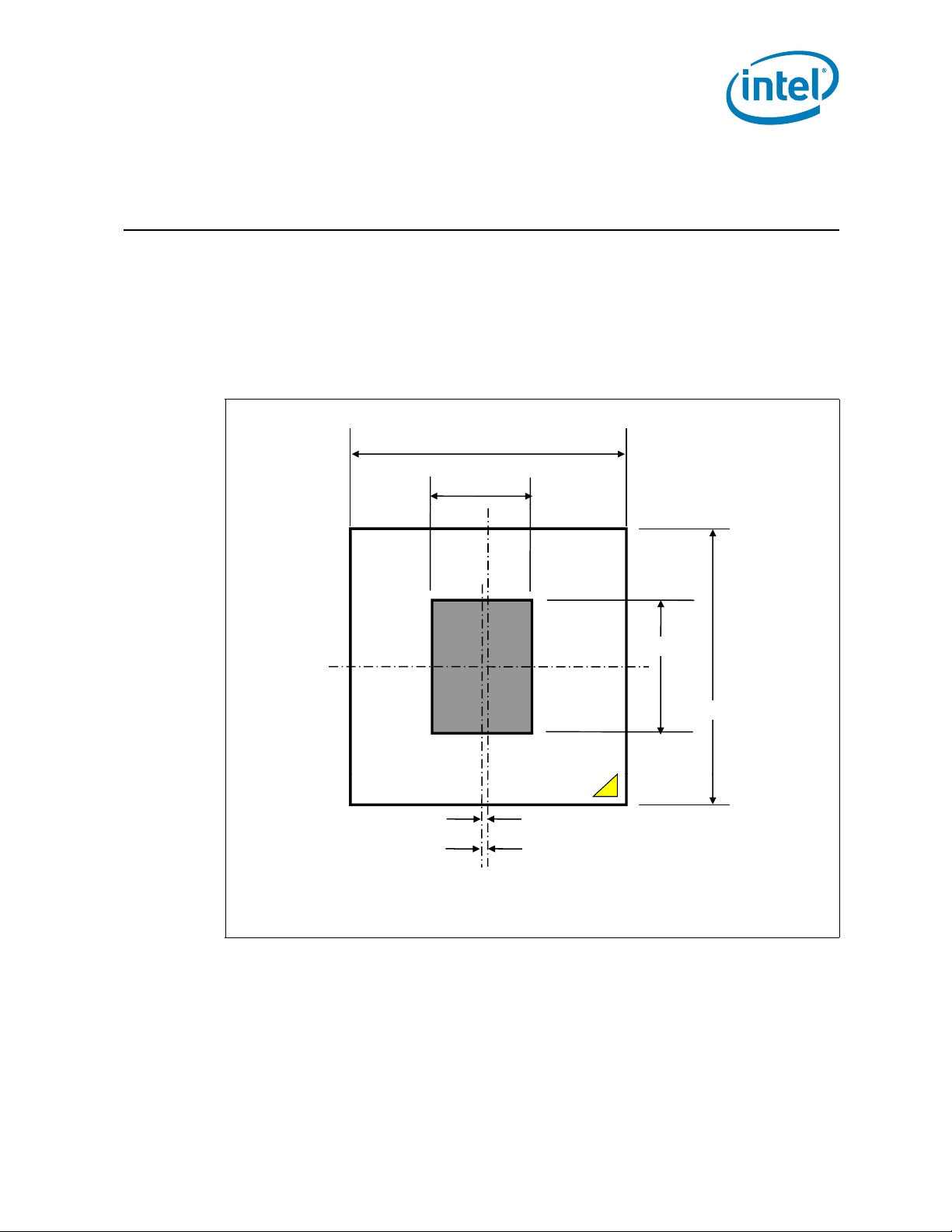
27.000
9.525
10.574
27.000
0.440
Package CenterlineDie Centerline
2 Packaging Mechanical
Specifications
2.1 PCH Package for Single Processor Desktop
The Platform Controller Hub uses a 27 mm square flip chip ball grid array (FC-BGA)
package (see Figure 2-1 through Figure 2-3). The complete package drawing can be
found in Appendix B.
Figure 2-1. Package Dimensions (Top View)
Note:
1. All dimensions in mm
Thermal Mechanical Specifications and Design Guidelines 9
Page 10
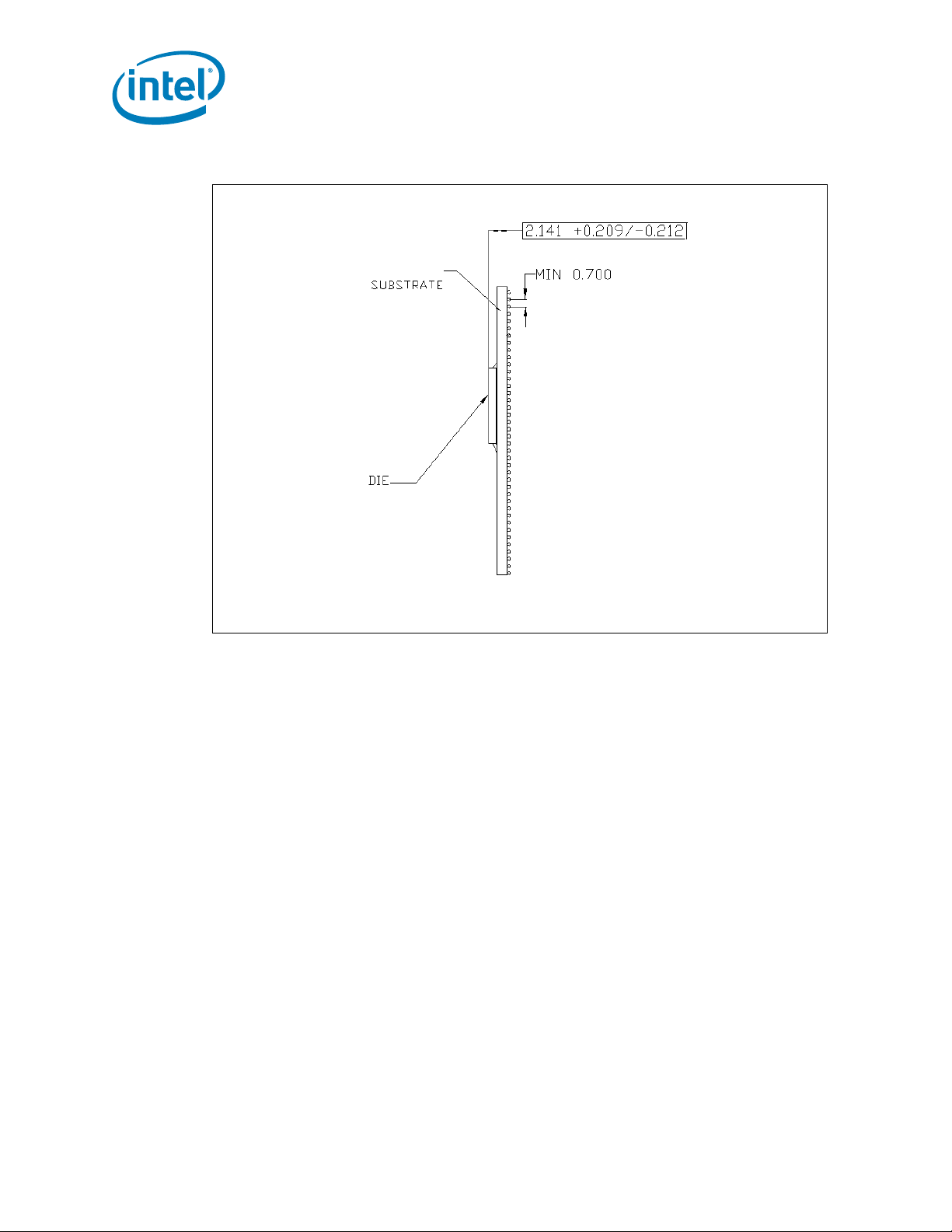
Figure 2-2. Package Dimensions (Side View)
Packaging Mechanical Specifications
Note: All dimensions in mm
10 Thermal Mechanical Specifications and Design Guidelines
Page 11

Packaging Mechanical Specifications
$
%8
Figure 2-3. Package (Land Side View)
Note: All dimensions in mm
2.2 Solder Balls
A total of 942 solder balls corresponding to the lands are on the bottom of the PCH
package for surface mounting with the motherboard. The package solder ball has the
following characteristics:
• Lead free SAC (SnAgCu) 405 solder alloy with a silver (Ag) content between 3%
and 4% and a melting temperature of approximately 217 °C. The alloy is
compatible with immersion silver (ImAg) and Organic Solderability Protectant
(OSP) motherboard surface finishes and a SAC alloy solder paste.
• Solder ball diameter 17 mil [0.4138 mm], before attaching to the package.
Thermal Mechanical Specifications and Design Guidelines 11
Page 12

Packaging Mechanical Specifications
2.3 Package Mechanical Requirements
The package has a bare die that is capable of sustaining a maximum static normal load
of 15 lbf (67 N).
Note: The heatsink attach solutions must not induce continuous stress to the package with
Note: These specifications apply to uniform compressive loading in a direction perpendicular
Note: These specifications are based on limited testing for design characterization. Loading
the exception of a uniform load to maintain the heatsink-to-package thermal interface.
to the die top surface.
limits are for the package only.
§ §
12 Thermal Mechanical Specifications and Design Guidelines
Page 13

Thermal Specifications
3 Thermal Specifications
To ensure proper operation and reliability of the PCH, the case (or junction)
temperature must be at or below the maximum value specified in Table 3-1. System
and/or component level thermal solutions are required to maintain these temperature
specifications. Chapter 5 provides the thermal metrology guidelines for case
tempearture measurements.
3.1 Thermal Design Power (TDP)
Real applications are unlikely to cause the PCH component to consume maximum
power dissipation for sustained time periods. Therefore, in order to arrive at a more
realistic power level for thermal design purposes, Intel characterizes power
consumption to reach a Thermal Design Power (TDP). TDP is the target power level to
which the thermal solutions should be designed. TDP is not the maximum power that
the PCH can dissipat e , see Table 3-1.
TDP condition is a set of applications when run simultaneously, would stress all its
features and dissipate power equivalent to TDP in the worst leakage scenario, see
Table 3-2. The configuration of PCH TDP is in Table 3-3.
3.2 Thermal Specifications
The data in Table 3-1 is based on post-silicon power measurements for the PCH. The
TDP, Idle, S3 and S5 (deep Sx) values are based on system configuration, see the
notes of Table 3-1. Intel recommends designing the PCH thermal solution to the TDP
for maximum flexibility and reuse. The PCH package has poor heat transfer capability
into the board and has minimal thermal capability without thermal solutions. Intel
requires that system designers plan for an attached heatsink when using the PCH. The
reference thermal solution is described in Chapter 6.
Table 3-1. PCH Thermal Specifications (Sheet 1 of 2)
Parameter Value Notes
Tcase-max 104 °C
Tcase-min 0 °C
Tj,max 108 °C
Tcontrol 104 °C
1. The value is based on system configuration and applications running
TDP 6.1 W
Idle 2.77 W
Idle
(configuration 2)2.65 W
simultaneously, see Table 3-2 and Table 3-3.
2. The value measurement is based on a core voltage of 1.05V and Tj of Tj,max
1. The value is based on system configuration, see Table 3-4
2. The value measurement is based on a core voltage of 1.05 V and Tj of 50 °C
1. The value is based on system configuration, see Table 3-4 but disconnected
one Gen 2 SATA HDD
2. The value measurement is based on a core voltage of 1.05 V and Tj of 50 °C
Thermal Mechanical Specifications and Design Guidelines 13
Page 14

Table 3-1. PCH Thermal Specifications (Sheet 2 of 2)
Parameter Value Notes
Idle
(configuration
3)
S3 0.128 W The value measurement is based on Tj of 35°C
S5/ deep Sx <0.009 W The value measurement is based on Tj of 35°C
2.41 W
1. The value is based on system configuration, see Table 3-4
one Gen 2 SATA HDD and disabled integrated graphic and then installed an
external graphic card.
2. The value measurement is based on a core voltage of 1.05 V and Tj of 50 °C
Table 3-2. PCH TDP Workload Running Simultaneously
TDP Workload Description (Applications running concurrently)
Windows* 7 system back up (Video, Pictire, Music, etc...) to USB HDD
Printer emulation (print ASCII test file to USB thumbdrive)
NetBlast over LAN to emulate heavy web traffic (Local network, system 1)
Media download from digital camera
Large file copy from HDD to USB thumbdrive
NetBlast over WLAN to emulate heavy web traffic (Local network, system 2)
1080P HD Video Recording over PCIE
NetBlast over PCI-LAN card to emulate heavy web traffic (Local network, system 3)
Large file copy from USB thumbdrive to USB HDD
Web Camera 1600 x 1200 @ 30 fps active (running Skype)
Thermal Specifications
but disconnected
Table 3-3. PCH TDP Configuration (Sheet 1 of 2)
PCH Interfaces Connected and Active Notes
USB Port 0 Flash Drive High-speed
USB Port 1 External USB HDD High-speed
USB Port 2 Digital Camera High-speed
USB Port 3 Media Card Reader High-speed
USB Port 4 USB Keyboard Low-speed
USB Port 5 USB Mouse Low-speed
USB Port 6 MP3 Player High-speed
USB Port 7 Gaming Controller Low-speed
USB Port 10 WebCam (640x480) High-speed
USB Port 13 Printer High-speed
SATA Port 0 HDD Non-Raid OS Gen 3
SATA Port 1 HDD Raid Array Gen 3
SATA Port 2 HDD Raid Array Gen 2
SATA Port 3 HDD Raid Array Gen 2
SATA Port 4 DVD/CD RW ODD Gen 1
SATA Port 5 BD ODD Gen 1
PCIE Port 1 Lewisville Gbe
PCIE Port 3 HDMI* HDTV Recorder
PCIE Port 5 USB3 Dongle
PCIE Port 6 WiFi (Mini PCIE)
Display Link 1 DP 1920 x 1200, 60 Hz, 24bpp
14 Thermal Mechanical Specifications and Design Guidelines
Page 15

Thermal Specifications
Table 3-3. PCH TDP Configuration (Sheet 2 of 2)
PCH Interfaces Connected and Active Notes
Display Link 2 VGA 1920 x 1200, 60 Hz, 24bpp
Platform Audio Jacks Headphone/Microphone Combination
FDI x 2 x2 for each 1920x1200, 60 Hz, 24bpp
DMI x 4 Active
LPC I/F Active
PCI 1394 Controller Active
Table 3-4. PCH Idle Power Configuration
PCH Interfaces Link Utilization Notes
High Definition Audio Idle External Codec
USB Port 1 EHCI1 (Idle, ports in suspend) Low-speed Keyboard
USB Port 2 Low-speed Mouse
SATA Port 2 Windows 7 system Idle, LPM disabled Gen 2 HDD
SATA Port 3 Windows 7 system Idle, LPM disabled Gen 2 HDD
SATA Port 5 Windows 7 system Idle, LPM disabled Gen 1 ODD
PCIE Port 1 100% L1 x 1 device Lewisville Gbe
PCIE Port 2 100% L1 x 1 device (IEEE-1394b Controller)
Display Link 1 Active VGA 1920 x 1200, 60 Hz, 24bpp
FDI x 2 1920x1200, 60 Hz, 24bpp
Thermal Mechanical Specifications and Design Guidelines 15
Page 16

3.3 Storage Specifications
Table 3-5 includes a list of the specifications for device storage in terms of maximum
and minimum temperatures and relative humidity. These conditions should not be
exceeded in storage or transportation.
Table 3-5. Storage Conditions
Parameter Description Min Max Notes
The non-operating device storage temperature.
T
ABSOLUTE STORAGE
T
SUSTAINED STORAGE
RH
SUSTAINED STORAGE
TIME
SUSTAINED STORAGE
Note:
1. Refers to a component device that is not assembled in a board or socket that is not to be electrically
connected to a voltage reference or I/O signals.
2. Specified temperatures are based on data collected. Exceptions for surface mount reflow are specified in by
applicable JEDEC standard. Non-adherence may affect component reliability.
3. T
ABSOLUTE STORAGE
moisture barrier bags or desiccant.
®
4. Intel
5. The JEDEC, J-JSTD-020 moisture level rating and associated handling practices apply to all moisture
6. Nominal temperature and humidity conditions and durations are given and tested within the constraints
branded board products are certified to me et th e fol lowing temperat ure and humidity limits that are
given as an example only (Non-Operating Temperature Limit: -40 °C to 70 °C & Humidity: 50% to 90%,
non-condensing with a maximum wet bulb of 28 °C). Post board attach storage temperature limits are not
specified for non-Intel
sensitive devices removed from the moisture barrier bag.
imposed by Tsustained and customer shelf life in applicable Intel
Damage (latent or otherwise) may occur when
subjected to for any length of time.
The ambient storage temperature limit (in shipping
media) for a sustained period of time.
The maximum device storage relative humidity for
a sustained period of time.
A prolonged or extended period of time; typically
associated with customer shelf life.
applies to the unassembled component only and does not apply to the shipping media,
®
branded boards.
Months6 Months
®
box and bags.
Thermal Specifications
-55 °C 125 °C 1, 2, 3
-5 °C 40 °C 4, 5
60% @ 24 °C 5, 6
0
6
§ §
16 Thermal Mechanical Specifications and Design Guidelines
Page 17

Thermal Simulation
4 Thermal Simulation
Intel provides thermal simulation models of the PCH and associated users’ guides to aid
system designers in simulating, analyzing, and optimizing their thermal solutions in an
integrated, system-level environment. The models are for use with the commercially
available Computational Fluid Dynamics (CFD)-based thermal analysis tool FLOTHERM*
(version 5.1 or higher) by Flomerics, Inc. and Icepak* by Fluent. Contact your Intel
field sales representative to order the thermal models and users’ guides.
§ §
Thermal Mechanical Specifications and Design Guidelines 17
Page 18

Thermal Simulation
18 Thermal Mechanical Specifications and Design Guidelines
Page 19

Thermal Metrology
Start
End
Attach
thermocouple.
Setup the system
in the desired
configuration
Revise
Heatsink or
Boundary
Conditions
Run representative
workload for the
configuration and
monitor the device
temperature
Temperature >
Specification?
Attach the
device to the
board using
normal reflow
process
Yes
No
Start
End
Attach
thermocouple.
Setup the system
in the desired
configuration
Revise
Heatsink or
Boundary
Conditions
Run representative
workload for the
configuration and
monitor the device
temperature
Temperature >
Specification?
Attach the
device to the
board using
normal reflow
process
Yes
No
5 Thermal Metrology
The system designer must make temperature measurements to accurately determine
the thermal performance of the system. Intel has established guidelines for proper
techniques to measure the PCH case and junction temperatures. The flowchart in
Figure 5-1 offers useful guidelines for thermal performance and evaluation.
Figure 5-1. Thermal Solution Decision Flow Chart
5.1 Tcase Temperature Measurements
To ensure functionality and reliability, the T
between the maximum/minimum operating range of the temperature specification as
noted in Table 3-1. The surface temperature at the geometric center of the die
corresponds to T
. Measuring T
case
requires special care to ensure an accurate
case
temperature measurement.
T emperature differences between the surface and the surrounding local ambient air can
introduce errors in the measurements. The measurement errors could be due to a poor
thermal contact between the thermocouple junction and the surface of the package,
heat loss by radiation and/or convection, conduction through thermocouple leads, and/
or contact between the thermocouple cement and the heatsink base (if a heatsink is
used). For maximum measurement accuracy, only the following thermocouple attach
approach is recommended.
5.1.1 Heatsink Thermocouple Attach Methodology
1. Mill a 3.3 mm (0.13 in.) diameter and 1.5 mm (0.06 in.) deep hole centered on the
bottom of the heatsink base.
2. Mill a 1.3 mm (0.05 in.) wide and 0.5 mm (0.02 in.) deep slot from the centered
hole to one edge of the heatsink. The slot should be parallel to the heatsink fins
(see Figure 5-2).
3. Attach thermal interface material (TIM) to the bottom of the heatsink base.
of the PCH must be maintained at or
case
Thermal Mechanical Specifications and Design Guidelines 19
Page 20

4. Cut out portions of the TIM to make room for the thermocouple wire and bead. The
Cement +
Thermocouple Bead
Die
Thermocouple
Wire
Substrate
cutouts should match the slot and hole milled into the heatsink base.
5. Attach a 36 gauge or smaller calibrated K-type thermocouple bead or junction to
the center of the top surface of the die using a high thermal conductivity cement.
During this step, ensure no contact is present between the thermocouple cement
and the heatsink base because any contact will affect the thermocouple reading. It
is critical that the thermocouple bead makes contact with the die (see Figure 5-3).
6. Attach heatsink assembly to the package and route thermocouple wires out
through the milled slot.
Figure 5-2. Heatsink Modifications
Thermal Metrology
Note: Not to Scale
Figure 5-3. Top View of Package
20 Thermal Mechanical Specifications and Design Guidelines
Page 21

Thermal Metrology
5.2 Ambient Temperature and Airflow Measurement
Figure 5-4 describes the recommended location for air temperature measurements
measured relative to the component. For a more accur ate measurement of the av erage
approach air temperature, Intel recommends averaging temperatures recorded from
two thermocouples spaced about 25 mm [1.0 in] apart. Locations for both a single
thermocouple and a pair of thermocouples are presented.
Airflow velocity should be measured using industry standard air velocity sensors.T ypical
airflow sensor technology may include hot wire anemometers.
Figure 5-4 provides guidance for airflow velocity measurement locations. These
locations are for a typical JEDEC test setup and may not be compatible with all chassis
layouts due to the proximity of the PCI and PCI Express* add-in cards to the
component. The user may have to adjust the locations for a specific chassis. Be aware
that sensors may need to be aligned perpendicular to the airflow velocity vector or an
inaccurate measurement may result. Measurements should be taken with the chassis
fully sealed in its operational configuration to achieve a representative airflow profile
within the chassis.
Figure 5-4. Airflow & Temperature Measurement Locations
§ §
Thermal Mechanical Specifications and Design Guidelines 21
Page 22

Thermal Metrology
22 Thermal Mechanical Specifications and Design Guidelines
Page 23

ATX Reference Thermal Solution
6 ATX Reference Thermal
Solution
Note: The reference thermal mechanical solution information shown in this document
represents the current state of the design. The data is subject to modification and
represents design targets, not commitments by Intel.
The design strategy for the PCH thermal solution is to reuse the z-clip heatsink
originally designed for the I/O Controller Hub 6 (ICH6) Family and used on subsequent
ICH designs through ICH10 and also for Intel® 5 Series Chipset design.
This section describes the overall requirements for the A TX heatsink reference thermal
solution including critical-to-function dimensions, operating environment, and
validation criteria. Other chipset components may or may not need attached thermal
solutions depending on your specific system local-ambient operating conditions.
6.1 Reference Solution
The reference solution is an extruded aluminum heatsink with pre-applied phase
change thermal interface material (TIM). The TIM is a Chomerics T710. The reference
solution is provided as an assembly with the clip, TIM and extrusion. See Appendix B
for the complete set of mechanical drawings including the motherboard keep-out zone.
The reference design z-clip centers the load on the die and by design will keep the
heatsink flush and parallel with the top surface of the die. The TIM size in the reference
design is larger than the die area. The resistivity of the TIM is 5 x 10^16 Ohm-cm. Any
TIM material that comes in contact with die side capacitors (DSC) will not cause a
short.
During the heatsink assembly process the heatsink may come in contact with DSC. The
maximum spring force allowed for the reference design z-clip has not been shown to
cause damage to DSC during assembly.
Thermal Mechanical Specifications and Design Guidelines 23
Page 24

Figure 6-1. Reference Thermal Solution
ATX Reference Thermal Solution
6.2 Environmental Reliability Requirements
The reference solution heatsink will be evaluated to the reliability requirements in
Table 6-1. The mechanical loading of the component may vary depending on the
heatsink, and attach method used. The customer should define a validation test suite
based on the anticipated use conditions and resulting reliability requirements. Thermal
cycling, bake and humidity tests were performed on original design and are not being
repeated. The designer should select appropriate thermal / humidity tests for the
expected use conditions.
Table 6-1. Reference Thermal Solution Environmental Reliability Requirements
Test Requirement Pass / Fail Criteria
3 drops for + and - directions in each of 3 perpendicular
Mechanical Shock
Random Vibration
axes (that is, total 18 drops).
Profile: 50 G trapezoidal waveform, 170 inches/sec.
minimum velocity change.
Setup: Mount sample board on test fixture
Duration: 10 min/axis, 3 axes
Frequency Range: 5 Hz to 500 Hz
Power Spectral Density (PSD) Profile: 3.13 g RMS
§ §
Visual\Electrical Check
Visual\Electrical Check
24 Thermal Mechanical Specifications and Design Guidelines
Page 25

Thermal Solution Component Vendors
A Thermal Solution Component
Vendors
Note: These vendors and devices are listed by Intel as a convenience to Intel's general
customer base, but Intel does not make any representations or warranties whatsoever
regarding quality, reliability, functionality, or compatibility of these devices. This list
and/or these devices may be subject to change without notice.
Table A-1. Reference Heatsink Enabled Components
Item Intel PN AVC CCI Foxconn Wieson
Heatsink
Assembly
Anchor A13494-008 HB9703E-DW G2100C888-064H
Table A-2. Supplier Contact Information
C46655-001 S702C00001 00C855802B 2Z802-009
Supplier Contact Phone
AVC
(Asia Vital Corporation)
CCI(Chaun Choung
Technology
Foxconn
Wieson
Kai Chang
Monica Chih
Harry Lin
Jack Chen
Wanchi Chen
Chary Lee
Henry Liu
+86 755 3366 8888
x63588
+886-2-2995-2666
(714) 739-5797
(408) 919-6121
(408) 919-6135
+886-2-2647-1896 ext. 6684
+886-2-2647-1896 ext.6330
kai_chang@avc.com.tw
monica_chih@ccic.com.tw
hlinack@aol.com
jack.chen@foxconn.com
wanchi.chen@foxconn.com
chary@wieson.com
henry@wieson.com
§ §
Thermal Mechanical Specifications and Design Guidelines 25
Page 26

Thermal Solution Component Vendors
26 Thermal Mechanical Specifications and Design Guidelines
Page 27

Mechanical Drawings for Package and Reference Thermal Solution
B Mechanical Drawings for
Package and Reference
Thermal Solution
The following mechanical drawings are included in this appendix:
Figure B-1, “Desktop Platform Controller Hub Package Drawing” on page 28
Figure B-2, “Motherboard Keep-Out for ATX Reference Heatsink” on page 29
Figure B-3, “ATX Reference Heatsink Assembly” on page 30
Figure B-4, “ATX Reference Heatsink Extrusion” on page 31
Figure B-5, “ATX Reference Heatsink Clip” on page 32
Thermal Mechanical Specifications and Design Guidelines 27
Page 28

Mechanical Drawings for Package and Reference Thermal Solution
Figure B-1. Desktop Platform Controller Hub Package Drawing
28 Thermal Mechanical Specifications and Design Guidelines
Page 29

Mechanical Drawings for Package and Reference Thermal Solution
13
4
5678
B
C
D
A
123
4
5678
B
C
D
A
THIS DRAWING CONTAINS INTEL CORPORATION CONFIDENTIAL INFORMATION. IT IS DISCLOSED IN CONFIDENCE AND ITS CONTENTS
MAY NOT BE DISCLOSED, REPRODUCED, DISPLAYED OR MODIFIED, WITHOUT THE PRIOR WRITTEN CONSENT OF INTEL CORPORATION.
SHEET 1 OF 1DO NOT SCALE DRAWINGSCALE: 1
1.0C45961 D
REVDRAWING NUMBERCAGE CODESIZE
ICH 6 KEEPOUT DRAWING
TITLE
2200 MISSION COLLEGE BLVD.
P.O. BOX 58119
SANTA CLARA, CA 95052-8119
CORP.
R
TMD
DEPARTMENT
NA
FINISH:NAMATERIAL:
06/02/03D.CARTER
DATEAPPROVED BY
06/02/03F.ANDERS
DATECHECKED BY
06/01/03P. JOHNSON
DATECHECKED BY
5/30/03S.LOFLAND
DATEDESIGNED BY
UNLESS OTHERWISE SPECIFIED:
DIMENSIONS ARE IN MILLIMETERS.
INTERPRET DIMENSIONS AND TOLERANCES
PER ANSI Y14.5M-1994
THIRD ANGLE PROJECTION
REVISION HISTORY
ZONE REV DESCRIPTION DATE APPROVED
*** 0.5 PRELIMINARY RELEASE 06/02/03 PJ
1.0 CHANGED REV FROM 0.5 TO 1.0 09/28/04 D.CARTER
C45961 1 1.0
DWG. NO SHT. REV
2X 22.39
.882[]
2X 5.08
.200[]
2X 4.19
.165[]
2X 8.76
.345[]
2X 2.11
.083[]
2X 1.85
.073[]
33
1.299[]
33
1.299[]
2X 27.43
1.080[]
2X 18.29
.720[]
4X PLATED THRU HOLE0.97 .038[]
2X 5
.197[]
5
.197[]
1.5 [ .059]
MAX COMPONENT HEIGHT
(NON-ICH COMPONENTS)
3.25 [ .125]
MAX COMPONENT HEIGHT
NO COMPONENTS THIS AREA
4X 1.42[.056] TRACE KEEPOUT
DETAIL A
DO NOT SCALE
SEE DETAIL A
COMPONENT CENTER
NOTES:
1 . HOLE PLACEMENT FABERICATION
TOLERANCE PER INTEL 454979, CLASS 1,2,3.
1
Figure B-2. Motherboard Keep-Out for ATX Reference Heatsink
Thermal Mechanical Specifications and Design Guidelines 29
Page 30

Mechanical Drawings for Package and Reference Thermal Solution
Figure B-3. ATX Reference Heatsink Assembly
30 Thermal Mechanical Specifications and Design Guidelines
Page 31

Mechanical Drawings for Package and Reference Thermal Solution
Figure B-4. ATX Reference Heatsink Extrusion
Thermal Mechanical Specifications and Design Guidelines 31
Page 32

Mechanical Drawings for Package and Reference Thermal Solution
Figure B-5. ATX Reference Heatsink Clip
§ §
32 Thermal Mechanical Specifications and Design Guidelines
 Loading...