

Integra DTM-5.9 Owner's Manual

Stereo Receiver
DTM-5.9
Instruction Manual

WARNING:
TO REDUCE THE RISK OF FIRE OR ELECTRIC
SHOCK, DO NOT EXPOSE THIS APPARATUS
TO RAIN OR MOISTURE.
CAUTION:
TO REDUCE THE RISK OF ELECTRIC SHOCK,
DO NOT REMOVE COVER (OR BACK). NO
USER-SERVICEABLE PARTS INSIDE. REFER
SERVICING TO QUALIFIED SERVICE
PERSONNEL.
Important Safety Instructions
1. Read these instructions.
2. Keep these instructions.
3. Heed all warnings.
4. Follow all instructions.
5. Do not use this apparatus near water.
6. Clean only with dry cloth.
7. Do not block any ventilation openings. Install in
accordance with the manufacturer’s instructions.
8. Do not install near any heat sources such as
radiators, heat registers, stoves, or other apparatus
(including amplifiers) that produce heat.
9. Do not defeat the safety purpose of the polarized or
grounding-type plug. A polarized plug has two
blades with one wider than the other. A grounding
type plug has two blades and a third grounding
prong. The wide blade or the third prong are
provided for your safety. If the provided plug does
not fit into your outlet, consult an electrician for
replacement of the obsolete outlet.
10. Protect the power cord from being walked on or
pinched particularly at plugs, convenience
receptacles, and the point where they exit from the
apparatus.
11. Only use attachments/accessories specified by the
manufacturer.
12. Use only with the cart,
stand, tripod, bracket, or
table specified by the
manufacturer, or sold with
the apparatus. When a cart
is used, use caution when
moving the cart/apparatus
combination to avoid injury
from tip-over.
13. Unplug this apparatus during lightning storms or
when unused for long periods of time.
14. Refer all servicing to qualified service personnel.
Servicing is required when the apparatus has been
damaged in any way, such as power-supply cord or
plug is damaged, liquid has been spilled or objects
have fallen into the apparatus, the apparatus has
been exposed to rain or moisture, does not operate
normally, or has been dropped.
PORTABLE CART WARNING
S3125A
WARNING
RISK OF ELECTRIC SHOCK
DO NOT OPEN
The lightning flash with arrowhead symbol, within an
equilateral triangle, is intended to alert the user to the
presence of uninsulated “dangerous voltage” within
the product’s enclosure that may be of sufficient
magnitude to constitute a risk of electric shock to
persons.
The exclamation point within an equilateral triangle is
intended to alert the user to the presence of important
operating and maintenance (servicing) instructions in
the literature accompanying the appliance.
AVIS
RISQUE DE CHOC ELECTRIQUE
NE PAS
OUVRIR
15. Damage Requiring Service
Unplug the apparatus from the wall outlet and refer
servicing to qualified service personnel under the
following conditions:
A. When the power-supply cord or plug is
damaged,
B. If liquid has been spilled, or objects have fallen
into the apparatus,
C. If the apparatus has been exposed to rain or
water,
D. If the apparatus does not operate normally by
following the operating instructions. Adjust only
those controls that are covered by the operating
instructions as an improper adjustment of other
controls may result in damage and will often
require extensive work by a qualified technician
to restore the apparatus to its normal operation,
E. If the apparatus has been dropped or damaged in
any way, and
F . When the apparatus exhibits a distinct change in
performance this indicates a need for service.
16. Object and Liquid Entry
Never push objects of any kind into the apparatus
through openings as they may touch dangerous
voltage points or short-out parts that could result in
a fire or electric shock.
The apparatus shall not be exposed to dripping or
splashing and no objects filled with liquids, such as
vases shall be placed on the apparatus.
Don’t put candles or other burning objects on top of
this unit.
17. Batteries
Always consider the environmental issues and
follow local regulations when disposing of batteries.
18. If you install the apparatus in a built-in installation,
such as a bookcase or rack, ensure that there is
adequate ventilation.
Leave 20 cm (8") of free space at the top and sides
and 10 cm (4") at the rear. The rear edge of the shelf
or board above the apparatus shall be set 10 cm (4")
away from the rear panel or wall, creating a flue-like
gap for warm air to escape.
2

Precautions
1. Recording Copyright
only, recording copyrighted material is illegal
without the permission of the copyright holder.
2. AC Fuse
serviceable. If you cannot turn on the unit, contact
the dealer from whom you purchased this unit.
3. Care —Occasionally you should dust the unit all
over with a soft cloth. For stubborn stains, use a soft
cloth dampened with a weak solution of mild
detergent and water. Dry the unit immediately
afterwards with a clean cloth. Don’t use abrasive
cloths, thinners, alcohol, or other chemical solvents,
because they may damage the finish or remove the
panel lettering.
4. Power
WARNING
BEFORE PLUGGING IN THE UNIT FOR THE
FIRST TIME, READ THE FOLLOWING
SECTION CAREFULLY.
AC outlet voltages vary from country to country.
Make sure that the voltage in your area meets the
voltage requirements printed on the unit’ s rear panel
(e.g., AC 230, 50 Hz or AC 120 V, 60 Hz).
The power cord plug is used to disconnect this unit
from the AC power source. Make sure that the plug
is readily operable (easily accessible) at all times.
Some models have a voltage selector for
compatibility with power systems around the world.
Before you plug in such a model, make sure that the
voltage selector is set to the correct voltage for your
area.
Pressing the [On/Standby] button to select Standby
mode does not fully shutdown the unit. If you do
not intend to use the unit for an extended period,
remove the power cord from the AC outlet.
5. Preventing Hearing Loss
Caution
Excessive sound pressure from earphones and
headphones can cause hearing loss.
6. Batteries and Heat Exposure
Warning
Batteries (battery pack or batteries installed) shall
not be exposed to excessive heat as sunshine, fire or
the like.
7. Never Touch this Unit with Wet Hands—
handle this unit or its power cord while your hands
are wet or damp. If water or any other liquid gets
inside this unit, have it checked by the dealer from
whom you purchased this unit.
8. Handling Notes
• If you need to transport this unit, use the original
• Do not leave rubber or plastic items on this unit
—The AC fuse inside the unit is not user-
packaging to pack it how it was when you
originally bought it.
for a long time, because they may leave marks on
the case.
—Unless it’s for personal use
Never
• This unit’s top and rear panels may get warm
after prolonged use. This is normal.
• If you do not use this unit for a long time, it may
not work properly the next time you turn it on, so
be sure to use it occasionally.
For U.S. models
FCC Information for User
CAUTION:
The user changes or modifications not expressly
approved by the party responsible for compliance could
void the user’s authority to operate the equipment.
NOTE:
This equipment has been tested and found to comply
with the limits for a Class B digital device, pursuant to
Part 15 of the FCC Rules. These limits are designed to
provide reasonable protection against harmful interference in a residential installation.
This equipment generates, uses and can radiate radio
frequency energy and, if not installed and used in accordance with the instructions, may cause harmful interference to radio communications. However, there is no
guarantee that interference will not occur in a particular
installation. If this equipment does cause harmful interference to radio or television reception, which can be
determined by turning the equipment off and on, the
user is encouraged to try to correct the interference by
one or more of the following measures:
• Reorient or relocate the receiving antenna.
• Increase the separation between the equipment and
receiver.
• Connect the equipment into an outlet on a circuit different from that to which the receiver is connected.
• Consult the dealer or an experienced radio/TV technician for help.
For Canadian Models
NOTE:
COMPLIES WITH CANADIAN ICES-003.
For models having a power cord with a polarized plug:
CAUTION:
MATCH WIDE BLADE OF PLUG TO WIDE SLOT,
FULL Y INSERT .
THIS CLASS B DIGITAL APPARATUS
TO PREVENT ELECTRIC SHOCK,
Modèle pour les Canadien
REMARQUE:
LA CLASSE B EST CONFORME À LA NORME
NMB-003 DU CANADA.
Sur les modèles dont la fiche est polarisée:
ATTENTION:
ÉLECTRIQUES, INTRODUIRE LA LAME LA PLUS
LARGE DE LA FICHE DANS LA BORNE
CORRESPONDANTE DE LA PRISE ET POUSSER
JUSQU’AU FOND.
CET APPAREIL NUMÉRIQUE DE
POUR ÉVITER LES CHOCS
3

Table of Contents
Introduction 2
Connections 12
Enjoying Audio
Sources 21
Others
Troubleshooting
Specifications
43
45
Introduction
Important Safety Instructions..............2
Precautions...........................................3
Table of Contents .................................4
Supplied Accessories ..........................5
Installing the Batteries............................5
Features.................................................6
Getting to Know the Receiver .............7
Front Panel............................................. 7
Rear Panel ............................................. 8
Display.................................................... 9
Remote Controller ..............................10
Using the Remote Controller................11
Connections
Connecting Your Speakers................12
Speaker Connection Precautions......... 12
Connecting the Speaker Cables........... 12
Connecting a Powered Subwoofer....... 13
Connecting a Power Amplifier..............13
Configuring the Speaker Impedance.... 14
Connecting Antenna ..........................15
Connecting the Indoor FM Antenna ..... 15
Connecting the AM Loop Antenna ....... 15
Connecting an Outdoor FM Antenna.... 16
Connecting an Outdoor AM Antenna ... 16
Connecting Your Components..........17
Connecting a Turntable........................17
Connecting a CD Player....................... 17
Connecting a Recording Component... 18
Connecting a Remote Interactive Dock
(RI Dock)........................................18
Connecting a DVD Player .................... 18
Connecting a VCR................................ 19
Connecting a TV or Other Component with
an Audio Output............................... 19
Connecting Components.............. 19
Connecting the Power Cords of Other
Components.................................... 20
Connecting the Power Cord................. 20
Enjoying Audio Sources
Turning On the Receiver....................21
Turning On and Standby...................... 21
Changing the Input Display.................. 21
Enjoying Audio Sources....................22
Muting the receiver (remote controller
only)................................................. 23
Using Headphones............................... 23
Setting the Display Brightness ............. 23
Using the Sleep Timer (remote controller
only)................................................. 23
Using the Tone and Balance Controls.. 24
Setting the Direct Function...................24
Recording............................................25
Recording the Input Source.................. 25
Recording Audio and Video from Separate
Sources ........................................... 26
Listening to the Radio........................27
Listening to AM/FM Stations ................ 27
Naming Preset Channels ...................29
Entering a Name .................................. 29
Correcting a Character.........................29
Advanced Setup .................................30
Setting the Advanced Setup................. 30
Advanced Setup Menu.........................31
Changing the Remote Controller’s ID... 31
Zone 2..................................................32
Connecting Zone 2...............................32
Zone 2 Out Settings ............................. 33
Using Zone 2........................................34
Using the 12V Triggers......................... 36
Using the Remote Controller in Zone 2
and Multiroom Control Kits.............. 37
Controlling Other Components.........38
Controlling an Integra/Onkyo DVD
Player........................................... 38
Controlling an Integra/Onkyo CD
Player........................................39
Controlling an RI Dock ......................... 40
Controlling a Cassette Recorder.......... 41
Programming a remote control code for
controlling components connected
via ............................................ 42
Resetting the Remote Controller..........42
Others
Troubleshooting .................................43
Specifications .....................................45
4

Supplied Accessories
Make sure you have the following accessories:
Remote controller and two batteries (AA/R6)
Indoor FM antenna
AM loop antenna
* In catalogs and on packaging, the letter at the end of the
product name indicates the color. Specifications and
operation are the same regardless of color.
Installing the Batteries
Detach the battery cover by pressing the
1
tab and pulling up the cover.
Insert two AA-size batteries into the
2
battery compartment.
Carefully follow the polarity diagram (positive +
and negative - symbols) inside the battery
compartment.
After batteries are installed and seated
3
correctly, attach the compartment cover.
Notes:
• If the remote controller doesn’t work reliably, try
replacing the batteries.
• Don’t mix new and old batteries or different types of
batteries.
• If you intend not to use the remote controller for a long
time, remove the batteries to prevent damage from
leakage or corrosion.
• Expired batteries should be removed as soon as
possible to prevent damage from leakage or
corrosion.
5

Features
❑
Brushed Hairline Aluminum Front Panel
❑
100 Watts/Channel @ 8 ohms (FTC)
❑
WRAT (Wide Range Amplifier Technology)
❑
High-Current, Low-Impedance Drive
❑
Discrete Output Stage Circuitry
❑
XM and SIRIUS Ready
❑
6 Audio Inputs (CD, TAPE, GAME/TV,
CBL/SAT, DVD, VCR/DVR)
❑
4 Video Inputs (GAME/TV, CBL/SAT, DVD,
VCR/DVR)
❑
Phono Input
❑
2 Audio and Video Outputs
❑
Speaker A/B T erminals
❑
Direct Mode
❑
IR Input/Output
❑
Banana Plug-Compatible Speaker Posts
❑
Compatible with RI Dock for the iPod
*
XM Ready
Inc. ©2008 XM Satellite Radio Inc. All rights reserved.
©2005 SIRIUS Satellite Radio Inc. “SIRIUS”, Sirius Connect,
the SIRIUS dog logo, channel names and logos are trademarks
of SIRIUS Satellite Radio Inc. Available only in the contiguous
United States (excluding Alaska and Hawaii) and Canada.
®
is a registered trademark of XM Satellite Radio
6

Getting to Know the Receiver
Front Panel
19K ML N23 567 8 J4
TV OU RPQS
For detailed information, see the pages in parentheses.
On/Standby button (21)
A
Sets the receiver to On or Standby.
B
Speakers A and B switches (22)
Turn speaker sets A and B on or off.
C
Standby indicator (21)
Lights up when the receiver is on Standby and
flashes while a signal is being received from the
remote controller.
D
Zone 2 Level, Tone, [
The Level button and [▲]/[▼] buttons are used
when adjusting the volume level of Zone 2.
The Tone button and [▲]/[▼] buttons are used when
adjusting the Bass/Treble lev el and balance of Zone 2.
E
Zone 2/Off buttons (34)
The Zone 2 button is used when setting Zone 2.
The OFF button is used to turn off Zone 2.
F
Remote-control sensor (11)
Receives control signals from the remote controller.
G
Display button
Displays various information about the currently
selected input source.
H
Direct button (24)
Outputs the original sound source without applying
any effect.
I
Tuning Up/Down buttons (27)
Used for radio tuning.
J
Character button (29)
Used to label the FM or AM station preset number.
K
Number buttons (28)
Used to select a station by entering the frequency
directly or to enter characters to label the station
preset number.
▲
] / [
▼
] buttons (35)
L Enter button
Used to select satellite radio stations.
M Direct Tuning button (28)
When you know the frequency for the station you
want to listen to, you can select the station by
entering the frequency directly using this button and
number buttons.
N Master Volume control (22)
Sets the volume of the receiver.
O Balance control (24)
This control is for adjusting the sound level balance
between the left and right channel for speakers and
headphones.
P Treble control (24)
This control is for adjusting the level of treble
sounds.
Q Bass control (24)
This control is for adjusting the level of bass
sounds.
R Tuning mode button (27, 28)
Selects the Auto or Manual tuning mode for AM
and FM radio.
S Memory button (28)
Used when storing or deleting radio presets.
T Input selector buttons (22, 25)
Used to select the input sources.
U Zone 2 indicator (34)
Flashes when Zone 2 is being set. Light up when
Zone 2 is on.
V Phones jack (23)
This 1/4-inch phone jack is for connecting a
standard pair of stereo headphones for private
listening.
7
Getting to Know the Receiver—Continued
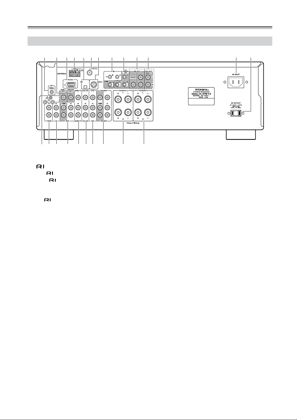
Rear Panel
B
1 4 6 9 J K L M
NOP Q R ST U V W
378
5
A REMOTE CONTROL jack
This (Remote Interactive) jack can be connected
to the jacks on your other Integra/Onkyo audio
components. The receiver’s remote controller can
then be used to control all of your components. To
use , you must make an analog audio connection
between the receiver and each component.
B MONITOR OUT
This jack is for connecting a TV with a composite
video output.
C RS232
This port is for connecting the receiver to home
automation equipment and external controllers.
D AM ANTENNA
These push terminals are for connecting an AM
antenna.
E XM antenna
This jack is for connecting a satellite radio such as
the XM Mini-Tuner System, sold separately.
F FM ANTENNA
This jack is for connecting an FM antenna.
G SIRIUS antenna
This jack is for connecting a SIRIUS digital
antenna, sold separately (see the separate SIRIUS
instructions).
H IR IN A/B and OUT
A commercially available IR receiver can be
connected to the IR IN A or B jack, allo wing you to
control the receiver while you’re in Zone 2, or
control it when it’s out of sight, for example,
installed in a cabinet.
A commercially available IR emitter can be
connected to the IR OUT jack to pass IR (infrared)
remote control signals along to other components.
I 12V TRIGGER OUT (A/B/C)
These outputs can be connected to the 12-volt
trigger inputs on other components.
J PRE OUT: L/R, SUBWOOFER
This analog audio output can be connected to the
analog audio input on a power amplifier when you
want to use the receiver solely as a preamplifier . The
SUBWOOFER jack is for connecting a powered
subwoofer.
K Zone 2 PRE OUT L/R
These analog audio outputs can be connected to the
line inputs on amplifiers in Zone 2.
L AC INLET
The supplied power cord is connected here. The
other end of the power cord should be connected to
a suitable wall outlet.
M AC OUTLET
This switched AC outlet can be used to supply
power to another component. The type of outlet
depends on the country in which you purchased
your receiver.
N Zone 2 VIDEO OUT
This video output is for connecting video input in
Zone 2.
O PHONO (MM) input and grounding terminal
This analog audio input is for connecting a turntable
with a moving-magnet cartridge. The screw located
on the upper-left of the PHONO (MM) inputs is for
connecting a turntable’s ground wire.
P CD input
This analog audio input is for connecting a CD
player’s analog audio output.
8
Getting to Know the Receiver—Continued
Q TAPE IN/OUT
This analog audio input and output are for
connecting a recorder with an analog audio input
and output, such as a cassette deck, MD recorder,
etc.
R GAME/TV IN
A game console or TV output can be connected
here. There are composite video input jack and
analog audio input jacks.
S CBL/SAT IN
A cable or satellite receiver can be connected here.
There are composite video input jack and analog
audio input jacks.
T DVD IN
These jacks are for connecting a DVD player . There
are composite video input jack for connecting the
video signal, and stereo (FRONT) jacks for
connecting the analog audio signals.
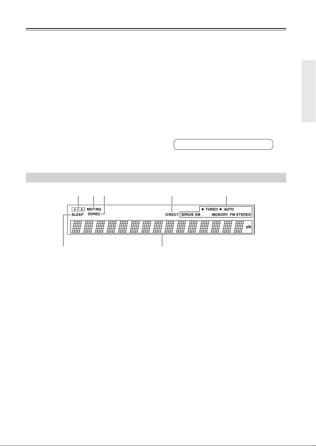
Display
21
354
U VCR/DVR IN/OUT
A video component, such as a VCR or D VR, can be
connected here for recording and playback. There
are composite video input and output jacks for
connecting the video signal, and there are analog
audio input jacks for connecting the audio signal.
V Speakers A
These terminal posts are for connecting speaker
set A.
W Speakers B
These terminal posts are for connecting speaker
set B.
See pages 12–20 for hookup information.
6
For detailed information, see the pages in parentheses.
1 A and B speaker indicators
Indicator A lights up when speaker set A is on.
Indicator B lights up when speaker set B is on.
2 Muting indicator
Flashes while the receiver is muted.
3 Zone 2 indicator
Lights up when Zone 2 is on.
4 Direct indicator
Lights up while the Direct function is enabled.
7
5 Radio indicators
TUNED: Lights up when tuned to a radio station.
AUTO: For AM and FM radio, lights up when Auto
Tuning is selected, and disappears when Manual
Tuning mode is selected.
SIRIUS : Lights up when tuned to SIRIUS Satellite
Radio.
XM : Lights up when tuned to XM Satellite Radio.
Memory: Lights up when presetting radio stations.
FM STEREO: Lights up when tuned to a stereo
FM station.
6 Sleep indicator
Lights up when the Sleep function has been set.
7 Message area
Displays various information about the selected
input source.
9

Remote Controller
T o control the AV receiver, press the [Receiver] Remote
Mode button to select Receiver mode.
You can also use the remote controller to control your
DVD player, CD player, and other components. See
pages 38-41 for more details.
For detailed information, see the pages in parentheses.
1
2
N
3
4
5
O
P
Q
6
7
8
R
9
J
S
K
L
M
A On/Standby button (21)
Sets the receiver to On or Standby.
B Zone 2 button (34)
Used when setting Zone 2.
C Input Selecter buttons (22) and number
buttons (28)
Selects the input sources. After the D.TUN b utton is
pressed, the buttons can be used to select AM and
FM radio stations and satellite radio channels
directly.
D D.TUN button (28)
Selects the Direct tuning mode.
E Dimmer button (23)
Adjusts the display brightness.
F Tuning Mode button (27, 28)
Selects the Auto or Manual tuning mode for AM
and FM radio.
G Tuning [ ]/[ ] buttons (27)
Used for radio tuning.
H SP A/B button (22)
Used for speaker A/B setting.
I Arrow [ ]/[ ]/[ ]/[ ] and Enter buttons
(27)
Used to select and adjust settings.
For XM/SIRIUS, the Up and Down [ ]/[ ]
buttons are used to select channels, and the [Enter]
button is used to change the search mode. The Left
and Right [ ]/[ ] buttons are used to select
categories.
J Setup button (14)
Used to access the setup menus.
K Stereo button
Used to cancel the Direct listening mode.
L Direct button (24)
Outputs the original sound source without applying
any effects.
M Display button
Displays various information about the selected
input source.
N Remote Mode buttons (38-41)
Selects the remote controller modes.
O CLR/Sleep button (23)
Used with the Sleep function.
P Preset [++
Used to select radio presets.
++
]/[−−−−] buttons (28)
Q Vol [ ]/[ ] buttons (22)
Adjusts the volume of the receiver re g ardless of the
currently selected remote controller mode.
R Muting button (23)
Mutes or unmutes the receiver.
10

Remote Controller—Continued
S Return button
Selects the previously displayed setup menu.
Note:
• An Onkyo cassette recorder connected via can
also be controlled in Receiver mode (see page
“Controlling a Cassette Recorder” on page 41).
Using the Remote Controller
Point the remote controller toward the remote control
sensor.
Remote control sensor
About 5 m
(16 feet)
Notes:
• The remote controller may not work reliably if the
receiver is subjected to bright light, such as direct
sunlight or inverter-type fluorescent lights. Keep this
in mind when installing.
• If another remote controller of the same type is used
in the same room, or the receiver is installed close to
equipment that uses infrared rays, the remote
controller may not work reliably.
• Don’t put anything, such as a book, on the remote
controller, because the buttons may be pressed
inadvertently, thereby draining the batteries.
• The remote controller may not work reliably if the
receiver is installed in a rack behind colored glass
doors. Keep this in mind when installing.
• The remote controller will not work if there’s an obstacle
between it and the receiver’s remote control sensor .
11

Connecting Y our Speakers
Disconnect the power cord from the wall outlet before making any connections.
Speaker Connection Precautions
The receiver allows you to connect tw o sets of speakers.
When two sets of speakers are connected, you can select
which speaker set outputs sound or use both sets to
output sound simultaneously.
• When you connect one set of speakers to either
Speakers A or Speak ers B terminal posts, or when you
connect two sets of speakers to both speaker terminal
posts and output sound only from either speaker set,
use speakers whose impedance is between 4 and 16
ohms. When the speaker impedance is 4 or 6 ohms, set
the speaker impedance setting on the receiver to 6
ohms (see page 14 for details).
• When you connect speakers to both SPEAKER A and
SPEAKER B terminal posts and output sound from
both speaker sets simultaneously , use speakers whose
impedance is between 8 and 16 ohms.
Note:
If you make an incorrect setting for the speakers or the
impedance values, the built-in protection circuit may be
activated resulting in no sound output from speakers.
The following illustration shows which speaker should
be connected to each pair of terminals.
Right
speaker
Speaker set A
+–
Left
speaker
+–
Connecting the Speaker Cables
Strip about 15 mm (5/8
1
inch) of insulation from
the ends of the speaker
cables, and twist the bare
wires tightly, as shown.
Unscrew the terminal.
2
Fully insert the bare
3
wires.
Screw the terminal tight.
4
• Read the instructions supplied with your speakers.
• Pay close attention to speaker wiring polarity . In other
words, connect positive (+) terminals only to positi ve
(+) terminals, and negative (–) terminals only to
negative (–) terminals. If you get them the wrong way
around, the sound will be out of phase and will sound
unnatural.
• Unnecessarily long or very thin speaker cables may
affect the sound quality and should be avoided.
• Be careful not to short the
positive and negative wires.
Doing so may damage the
receiver.
• Don’t connect more than one
cable to each speaker
terminal. Doing so may
damage the receiver.
• Don’t connect a speaker to more than one pair of
speaker terminals.
15 mm
(5/8")
12
Receiver
+– +–
Right
speaker
Speaker set B
Left
speaker

Connecting Y our Speakers—Continued
Connecting a Powered Subwoofer
Using a suitable cable, connect the receiver’s PRE OUT: SUBWOOFER to the input on your powered subwoofer. If
your subwoofer is unpowered and you’re using an external amplifier, connect the PRE OUT: SUBWOOFER to the
amp’s input.
Powered
subwoofer
LINE INPUT
LINE INPUT
Connecting a Power Amplifier
If you want to use a more powerful power amplifier and use the recei ver as a preamp, connect it to the PRE OUT jacks,
and connect all speakers and the subwoofer to the power amplifier. If you have a powered subwoofer, connect it to this
receiver’s PRE OUT SUBWOOFER jack.
Power amplifier
13

Connecting Y our Speakers—Continued
Configuring the Speaker Impedance
In this model, the factory default for speaker impedance is “8 ohms.” When you change the speaker impedance setting,
read “Speaker Connection Precautions” on page 12 carefully before performing the procedures below.
Note:
Be sure to minimize the volume level on the receiver
before configuring the speaker impedance.
Receiver
Enter
Set up
3
4
5
Use the Up and Down [▲]/[▼]
buttons to select “1. Hardware
set,” and then press [Enter].
The Hardware Setup menu appears on
the display.
Use the Up and Down [▲]/[▼]
buttons to select “Impedance: 8
ohms” indication.
Change the impedance value to
“6 ohms” using the Left and
Right [ ]/[ ] buttons.
14
1
2
Turn on the power.
Press the [Receiver] button and
then the Setup button on the
remote controller.
6
Press the Setup button on the
remote controller to complete the
setting.
When you restore the impedance
setting to 8 ohms, use the same
procedures above.

Connecting Antenna
This section explains how to connect the supplied indoor
FM antenna and AM loop antenna, and how to connect
commercially available outdoor FM and AM antennas.
The receiver won’t pick up an y radio signals without any
antenna connected, so you must connect the antenna to
use the tuner.
AM antenna push terminals
FM antenna connector
Connecting the Indoor FM Antenna
The supplied indoor FM antenna is for indoor use only.
Attach the FM antenna, as shown.
1
■ North American Model
Insert the plug fully
into the jack.
■ Other Models
Connecting the AM Loop Antenna
The supplied indoor AM loop antenna is for indoor use
only.
Assemble the AM loop antenna, inserting
1
the tabs into the base, as shown.
Connect both wires of the AM loop
2
antenna to the AM push terminals, as
shown.
(The antenna’s wires are not polarity sensiti ve, so
they can be connected either way around.)
Make sure that the wires are attached securely and
that the push terminals are gripping the bare
wires, not the insulation.
Push Insert wire Release
Insert the plug fully
into the jack.
Once your receiver is ready for use, you’ll need to
tune into an FM radio station and adjust the
position of the FM antenna to achieve the best
possible reception.
Use thumbtacks or something similar to
2
fix the FM antenna into position.
Thumbtacks, etc.
Caution: Be careful that you don’t injure yourself
when using thumbtacks.
If you cannot achieve good reception with the supplied
indoor FM antenna, try a commercially available
outdoor FM antenna instead (see page 16).
Once your receiver is ready for use, you’ll need to
tune into an AM radio station and adjust the
position of the AM antenna to achieve the best
possible reception.
Keep the antenna as far away as possible from
your receiver, TV, speaker cables, and power
cords.
If you cannot achieve good reception with the supplied
indoor AM loop antenna, try using it with a
commercially available outdoor AM antenna (see
page 16).
15
 Loading...