


RET basic

072010
50 008 00 b
BETRIEBSANLEITUNG DE 4
OPERATING INSTRUCTIONS EN 14
M
ODE D’EMPLOI FR 24
INDICACIONES DE SEGURIDAD ES 34
V
EILIGHEIDSINSTRUCTIES NL 36
N
ORME DI SICUREZZA IT 38
S
ÄKERHETSANVISNINGAR SV 40
S
IKKERHEDSHENVISNINGER DA 42
S
IKKERHEDSANVISNINGER NO 44
T
URVALLISUUSOHJEET FI 46
N
ORMAS DE SEGURANçA PT 48
W
SKAZÓWKI BEZPIECZEŃSTWA PL 50
B
EZPEČNOSTNÍ UPOZORNĚNÍ CS 52
B
IZTONSÁGI UTASITÁSOK HU 54
V
ARNOSTNA NAVODILA SL 56
B
EZPEČNOSTNÉ POKYNY SK 58
O
HUTUSJUHISED ET 60
D
ROŠĪBAS NORĀDES LV 62
S
AUGOS REIKALAVIMAI LT 64
IKA
®
-
WERKE
IKA
®
Reg.-No. 4343-01
REO basic
RET basic
safety control

3
092008
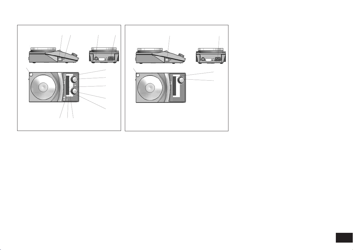
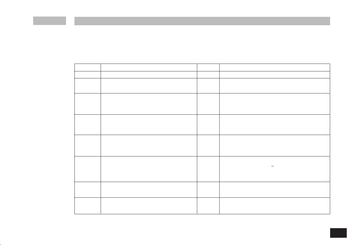
Pos Bezeichnung Item Designation Pos. Désignation
A Geräteschalter A Main Switch A Commutateur
B einstellbarer Sicherheitskreis B Adjustable safety circuit B Circuit de sécurité réglable
C Bedienknopf Heizung C Rotary knob, heater C Bouton rotatif de chauffage
D Bedienknopf Motor D Rotary knob, motor D Bouton rotatif du moteur
E LED-Display Heizung E LED display, heater E Affichage DEL chauffage
F LED-Display Motor F LED display, motor F Affichage DEL moteur
G LED Heizplatte G LED, heating plate G DEL plaque chauffante
H LED externer Temperatursensor H LED, external temperature sensor H DEL capteur de température externe
I LED (Set=Sollwert) I LED (set=set point value) I DEL (set=valeur théorique)
J LED externer Temperatursensor J LED, external temperature sensor J DEL capteur de température externe
K Netzbuchse K Power socket K Prise secteur
L Kontaktthermometerbuchse L Socket, contact thermometer L Prise du thermocontact
M Stativgewindebohrung M Threaded hole for stand M Alésage fileté du statif
A
Fig. 1
B
C
D
E
F
G
H
I
K
L
J
M
RET basic safety control
Fig. 2
A
K
D
F
REO basic
M

4
092008
Seite
CE - Konformitätserklärung 4
Sicherheitshinweise 4
Auspacken 6
Bestimmungsgemäßer Gebrauch 6
Bedienung 7
Betriebsmodi einstellen 8
Sicherheitstemperaturgrenze einstellen bei 8
RET basic safety control
Temperatur-Regelmodus einstellen bei 9
RET basic safety control
Montage Stativstab 9
Instandhaltung 10
Zubehör 10
Fehlercodes 11
Technische Daten 12
Gewährleistung 13
Wir erklären in alleiniger Verantwortung, dass dieses Produkt d
en
Bestimmungen der Richtlinien 2006/95/EG und 2004/108/EG ent-
spricht und mit den folgenden Normen und norminativen
Dokumenten übereinstimmt: DIN EN IEC 61010-1, -2-010 und
DIN EN IEC 61326-1.
Zu Ihrem Schutz
• Lesen Sie die Betriebsanleitung vor Inbetriebnahme voll-
ständig und beachten Sie die Sicherheitshinweise.
• Bewahren Sie die Betriebsanleitung für Alle zugänglich auf.
•
Beachten Sie, dass nur geschultes Personal mit dem Gerät arbeitet.
•
Beachten Sie die Sicherheitshinweise, Richtlinien, Arbeitsschutz -
und Unfallverhütungsvorschriften.
• Steckdose muss geerdet sein (Schutzleiterkontakt).
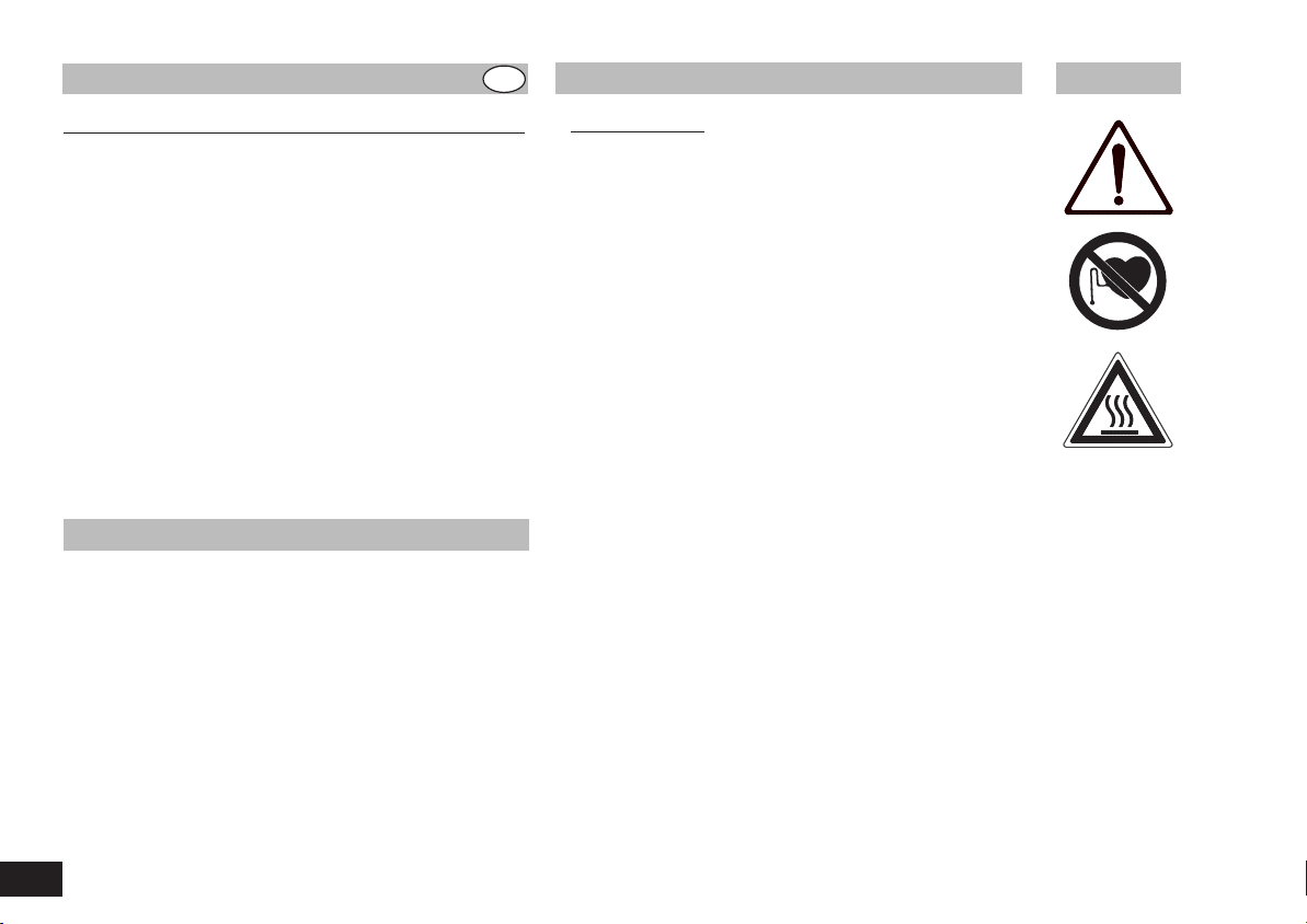
• Achtung - Magnetismus! Beachten Sie die Auswirkungen des
Magnetfeldes (Herzschrittmacher, Datenträger...).
• Verbrennungsgefahr! Vorsicht beim Berühren von Gehäuse-
teilen und Heizplatte. Die Heizplatte kann über 340 °C heiß wer-
den. Beachten Sie die Restwärme nach dem Ausschalten!
• Das Netzkabel darf die heizbare Aufstellplatte nicht berühren.
• Tragen Sie Ihre persönliche Schutzausrüstung entsprechend der
Gefahrenklasse d
es zu bearbeitenden Mediums. Ansonsten be-
steht eine Gefährdung durch:
- Spritzen und Verdampfen von Flüssigkeiten
- Herausschleudern von Teilen
- Freiwerden von toxischen oder brennbaren Gasen.
• Stellen Sie das Gerät frei auf einer ebenen, stabilen, sauberen,
rutschfesten, trockenen und feuerfesten Fläche auf.
• Die Gerätefüße müssen sauber und unbeschädigt sein.
• Prüfen Sie vor jeder Verwendung G
erät und Zubehör auf Be-
schädigungen. Verwenden Sie keine beschädigten Teile.
• Reduzieren Sie die Drehzahl, falls
- Medium infolge zu hoher Drehzahl aus dem Gefäß spritzt
- unruhiger Lauf auftritt
- das Gefäß sich auf der Aufstellplatte bewegt.
• Achtung! Mit diesem Gerät dürfen nur Medien bearbeitet bzw.
erhitzt werden, deren Flammpunkt über der eingestellten Sicher-
heitstemperaturbegrenzung liegt (50 .
.. 360 °C).
Die eingestellte Sicherheitstemperaturbegrenzung muss immmer
mindestens 25 °C unterhalb des Brennpunktes des verwendeten
Mediums liegen.
Inhaltsverzeichnis
CE-Konformitätserklärung
Sicherheitshinweise
DE

• Beachten Sie eine Gefährdung durch
- entzündliche Materialien
- brennbare Medien mit niedriger Siedetemperatur
- Glasbruch
- falsche Dimensionierung des Gefäßes
- zu hohen Füllstand des Mediums
- unsicherer Stand des Gefäßes.
• Im Betrieb kann sich das Gerät erwärmen.
• Die Aufstellpatte kann sich auch ohne Heizbetrieb durch den
Antriebsmagneten bei hohen Drehzahlen erwärmen.
• Verarbeiten Sie krankheitserregende M
aterialien nur in geschlos-
senen Gefäßen unter einem geeigneten Abzug. Bei Fragen
wenden Sie sich bitte an IKA.
• Betreiben Sie das Gerät nicht in explosionsgefährdeten Atmos-
phären, mit Gefahrstoffen und unter Wasser.
• Bearbeiten Sie nur Medien, bei denen der Energieeintrag durch
das Bearbeiten unbedenklich ist. Dies gilt auch für andere Ener-
gieeinträge, z.B. durch Lichteinstrahlung.
• Beachten S
ie die Betriebsanleitung des Zubehöres.
• Tauchen Sie externe Temperaturmessfühler (PT 1000, ETS-D...)
mindestens 20 mm tief in das Medium ein.
• Der angeschlossene externe Temperaturmessfühler PT 1000
muss sich immer im Medium befinden.
• Sicheres Arbeiten ist nur mit Zubehör, das im Kapitel „Zubehör“
beschrieben wird, gewährleistet.
• Zubehörteile müssen sicher mit dem Gerät verbunden sein und
dürfen s
ich nicht von alleine lösen. Der Schwerpunkt des
Aufbaus muss innerhalb der Aufstellfläche liegen.
• Montieren Sie Zubehör nur bei gezogenem Netzstecker.
• Die Trennung des Gerätes vom Stromversorgungsnetz erfolgt
nur durch Ziehen des Netz- bzw. Gerätesteckers.
• Die Steckdose für die Netzanschlussleitung muss leicht erreich-
bar und zugänglich sein.
• Nach einer Unterbrechung der Stromzufuhr läuft das Gerät im
Modus B von selbst wieder an.
• Eventuell kann Abrieb von rotierenden Zubehörteilen in das zu
bearbeitende Medium gelangen.
• Bei Verwendung von PTFE-ummantelten Magnetstäbchen ist
Folgendes zu beachten: Chemische Reaktionen von PTFE treten
ein im Kontakt mit geschmolzenen oder gelösten Alkali- und Erd-
alkalimetallen, sowie mit feinteiligen Pulvern von Metallen aus-
der 2. und 3. Gruppe des Periodensystems bei Temperaturen
über 300-400 °C. Nur elementares Fluor, Chlortrifluorid und
Alkalimetalle greifen es an,Halogenkohlenwasserstoffe w
irken
reversibel quellend.
(Quelle: Römpps Chemie-Lexikon und „Ullmann“ Bd.19)
Zum Schutz des Gerätes
• Das Gerät darf nur von einer Fachkraft geöffnet werden.
• Spannungsangabe des Typenschildes muss mit Netzspannung
übereinstimmen.
• Decken Sie das Gerät nicht ab, auch nicht teilweise, z.B. mit
metallischen Platten oder Folien. Die Folge ist Überhitzung.
• Vermeiden Sie Stöße und Schläge auf Gerät oder Zubehör.
• Achten Sie auf eine saubere Aufstellplatte.
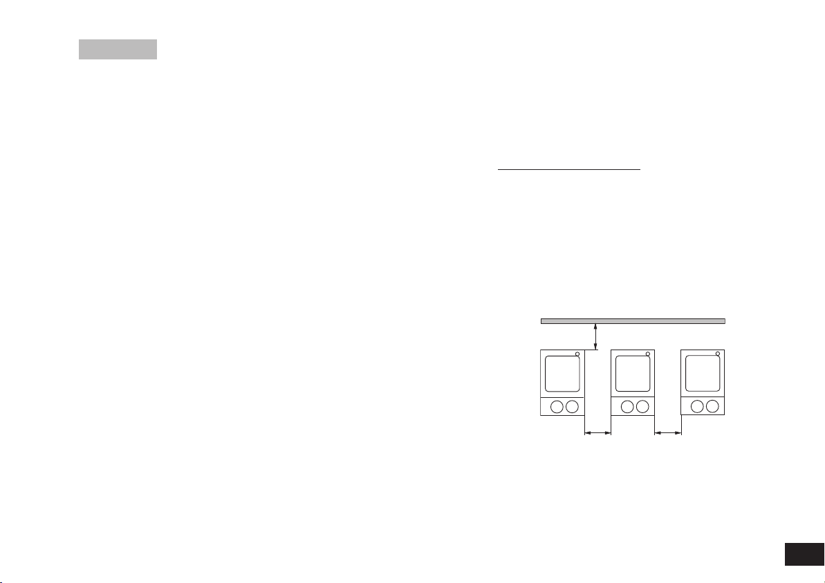
• Beachten Sie die Mindestabstände zwischen Geräten, zwischen Gerät
und Wand, sowie oberhalb des Aufbaus (min. 800 mm), siehe Fig. 3.
5
092008
> 100 mm > 100 mm
> 100 mm
Fig. 3

6
092008
•
Auspacken
- Packen Sie das Gerät vorsichtig aus
- Nehmen Sie bei Beschädigungen sofort den Tatbestand auf
(Post, Bahn oder Spedition)
•
Lieferumfang
REO basic RET basic safety control
- Magnetrührer - Beheizbarer Magnetrührer
- Netzkabel - Netzkabel
- Betriebsanleitung - Betriebsanleitung
- Schutzhaube - Schraubendreher
- Temperaturfühler PT 1000
- Schutzhaube
•
Verwendung
- zum Mischen und / oder Erhitzen von Flüssigkeiten
•
Verwendungsgebiet
- Laboratorien - Schulen
- Apotheken - Universitäten
Das Gerät ist für den Gebrauch in allen Bereichen geeignet, außer
Industriebereichen.
Der Schutz für den Benutzer ist nicht mehr gewährleistet, wenn das
Gerät mit Zubehör betrieben wird, welches nicht vom Hersteller gelie-
fert oder empfohlen wird oder wenn das Gerät in nicht bestimmungs-
gemäßem Gebrauch entgegen der Herstellervorgabe betrieben wird
oder wenn Veränderungen an Gerät oder Leiterplatte durch Dritte vor-
genommen
werden.
Auspacken Bestimmungsgemäßer Gebrauch
7
092008
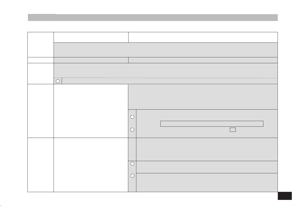
Inbetrieb-
nahme
Rühren
Heizen
Anschluss
externer
Thermometer
(direkte
Temperaturregel-
ung im Medium)
REO basic RET basic safety control
+
Geräteschalter (A) in OFF-Stellung bringen
+ Netzkabel in Netzbuchse (K) einstecken
+ Geräteschalter (A) in ON- Stellung bringen
„ Modus B ist fest voreingestellt „ Modus A ist eingestellt (siehe “Betriebsmodi”)
Bedienung
+ Motordrehzahl mit dem Bedienknopf (D) einstellen
„ Der
eingestellte Wert wird auf dem Display (F) angezeigt
+ Start der Rührfunktion durch Drücken des Bedienknopf (D)
„ Angezeigter Wert blinkt bis zum Erreichen der eingestellten Drehzahl
i
Vor Inbetriebnahme Schutzfolie von der Aufstellplatte entfernen!
+
Einstellen der Sicherheitstemperaturgrenze (siehe “Sicherheitstemperaturgrenze einstellen bei RET”)
+
Solltemperatur mit dem Bedienknopf (C) einstellen
„ Der
eingestellte Wert wird auf dem Display (E) angezeigt
+
Einstellen des Temperatur-Regelmodus
(siehe “Temperatur-Regelmodus einstellen bei RET”)
+ Start der Heizfunktion durch Drücken des Bedienknopfes (C) einstellen
Soll- und Ist- Temperatur wird im Wechsel a
uf dem Display (E) angezeigt:
„ Bei eingeschalteter Heizung leuchtet die LED (G), Solltemperaturanzeige LED (I) leuchtet
„ Solange die Temperatur der Aufstellfläche 50 °C überschreitet wird im Rühr- und Standby-
Betrieb auf dem Display (E) angezeigt
+ Geräteschalter (A) in OFF-Stellung bringen
+ Kontaktstecker (L) abziehen
+ Sicherheitskontaktthermometer nach DIN 12878 Klasse 2 oder
Temperaturfühler PT 1000 mit Buchse (L) verbinden
+ Geräteschalter (A) in ON-Stellung bringen
Temperaturfühler PT 1000
„ Die auf dem Display (E) angezeigte Ist-Temperatur des Tem-
peraturfühlers entspricht der Mediumstemperatur.
LED “externer Temperatursensor” (H) leuchte
t
K
ontatktthermometer z.B. ETS-D5
„ Bedienungsanweisung des Kontaktthermometers beachten
LED (J) “Dezimalpunkt der Temperaturanzeige” leuchtet
Auf dem Display (E) wird bei angeschlossenem Kontaktther-
mometer nur noch die eingestellte Soll- Temperatur angezeigt
HOt
i
i
i
i
Die einstellbare Heizplattentemperatur beträgt max. 340
°C
RET basic safety control
Gerätebetrieb mit Modus A oder B
Modus A
Alle eingestellten Werte bleiben nach dem Ausschalten oder dem
Trennen des Gerätes vom Netz erhalten. Nach dem Einschalten
des Gerätes ist der Status der Funktionen Rühren und Heizen aus-
geschaltet (OFF).
Modus B
Alle eingestellten Werte bleiben nach dem Ausschalten oder dem
Trennen des Gerätes vom Netz erhalten. Nach dem Einschalten
des Gerätes wird der Status der Funktionen Heizen und Rühren
vor dem letzten Ausschalten übernommen (ON oder OFF).
Werkseinstellung: Modus A
Der eingestellte Modus wird beim Start des
Gerätes auf dem Display angezeigt
Modus ändern
REO basic
Gerätebetrieb mit voreingestelltem Modus
Der Betriebsmodus ist fest eingestellt und nicht zu ändern.
Beschreibung Modus B und Darstellung Display siehe RET
REO basic Werkseinstellung: Modus B
Nach dem Einschalten des Gerätes wird die
eingestellte Sicherheitstemperaturgrenze
angezeigt.
Werkseinstellung: ca. 360 °C
Einstellbereich: > 50 - 360 °C
Sicherheitstemperaturgrenze einstellen
Die einstellbare Heizplattentemperatur von max. 340 °C liegt min-
destens 10 °C unter der eingestellten Sicherheitstemperturgrenze.
Achtung: Die eingestellte Sicherheitstemperaturgrenze muss
immer mindestens 25 °C unterhalb d
es Brennpunktes des zu
bearbeitenden Mediums liegen!
Funktionstest Sicherheitsskreisabschaltung
8
092008
Betriebsmodi einstellen
xx A
(xx: Softwareversion)
Modus
+ Geräteschalter (A) in OFF-Stellung bringen
+ Bedienknöpfe (C und D) gedrückt halten
+ Geräteschalter (A) in ON- Stellung bringen
+ Bedienknöpfe (C und D) loslassen
„
Anzeige
des eingestellten Wertes auf dem
Display
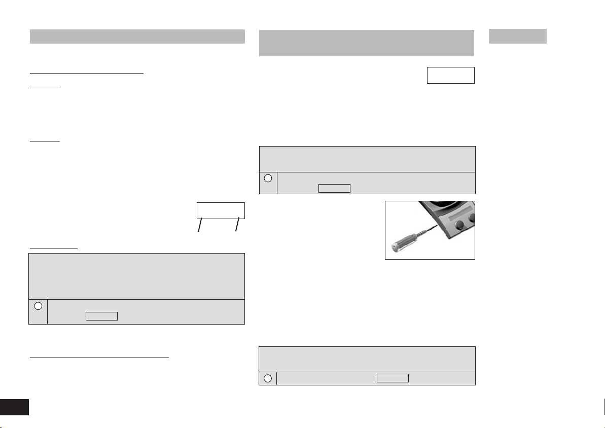
Sicherheitstemperaturgrenze einstellen bei
RET basic safety control
360 SAFE
+ Geräteschalter (A) in ON-Stellung bringen
+ Einstellen der Sicherheitstemperaturgrenze mit Schraubendreher
„
Anzeige
des eingestellten Wertes auf dem
Display
150 SAFE
i
i
xx A
Fig. 5
+ Sicherheitstemperaturgrenze auf Linksanschlag stellen (50 °C)
+ Geräteschalter (A) in ON-Stellung bringen
„
Anzeige
auf dem Display
i
Err 25
9
092008
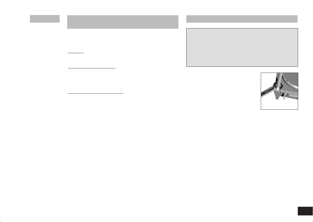
Montage Stativstab
+ Schraubstopfen (M) entfernen
+ Schutzkappe von Stativstab abziehen
+ Unterlegscheibe zwischen Gehäuse und Mutter legen
+ Stativstab von Hand bis zum Anschlag einschrauben
+ Mutter mit einem Gabelschlüssel SW17 anziehenå
+ Zubehör mit Kreuzmuffen montieren
Fig. 6
Hinweis: Zum Arbeiten mit Badaufsätzen
über ø 180 mm verwenden Sie bitte den
Stativstab H 16 V zusammen mit dem
Ausleger H 16.1.
Der Anwender kann beim Regeln mit einem externen PT1000-
Temperaturfühler zwischen zwei Arten der Regelung wählen:
PI-Modus
Gute Regelergebnisse, minimiertes Überschwingen, langsamer
2P-Modus (Zweipunktregler)
Maximale Aufheizgeschwindigkeit, größeres Überschwingen
Werkseinstellung: PI-Modus
Temperatur- Regelmodus ändern
1. Solltemperatur auf 2 °C einstellen
2. Gerät ausschalten
3. Temp-Drehknopf gedrückt halten
4. Gerät einschalten
Dadurch wird der Zweipunkt-Regler (2P) für den externen
PT 1000-Temperaturfühler aktiviert (2P erscheint auf der Anzeige)
bzw. deaktiviert.
Beim Einschalten des Gerätes wird bei aktiviertem Zweipunkt-
Regler neben der Betriebsart A/B auch 2P angezeigt.
Bei aktiver Heizfunktion im 2P-Mode (mit externem PT 1000-
Temperaturfühler) blinkt die Ist-Temperatur - das ist ein Hinweis
für den Anwender, dass die Mediumstemperatur stärker über-
schwingt!
Temperatur-Regelmodus einstellen bei
RET basic safety control

10
092008
Das Gerät arbeitet wartungsfrei.
Reinigung
Ziehen Sie zum Reinigen den Netzstecker.
Verwenden Sie nur von IKA empfohlene Reinigungsmittel.
Verwenden Sie zum Reinigen von:
Farbstoffen Isopropanol
Baustoffen Tensidhaltiges Wasser, Isopropanol
Kosmetika Tensidhaltiges Wasser, Isopropanol
Nahrungsmitteln Tensidhaltiges Wasser
Brennstoffen Tensidhaltiges Wasser
Beim Reinigen darf keine Feuchtigkeit in das Gerät dringen.
- Tragen Sie zum Reinigen des Gerätes Schutzhandschuhe.
- Falls andere als die empfohlenen Reinigungs- oder Dekontamina-
tionsmethoden angewendet werden, fragen Sie bitte bei IKA nach.
E
rsatzteilbestellung
Bei Ersatzteilbestellungen geben Sie bitte Folgendes an:
- Gerätetyp
- Fabrikationsnummer des Gerätes, siehe Typenschild
- Positionsnummer und Bezeichnung des Ersatzteiles,
siehe www.ika.net.
Reparaturfall
Im Reparaturfall muss das Gerät gereinigt und frei von gesund-
heitsgefährdenden Stoffen sein.
Senden Sie das Gerät in der Originalverpackung zurück. Lagerver-
packungen sind für den Rückversand nicht ausreichend. Verwen-
den Sie zusätzlich eine geeignete Transportverpackung.
• Rührstäbe: ø 6 mm, Länge bis 15 mm
ø 7 mm, Länge bis 60 mm
ø 10mm, Länge bis 80 mm
• RS 1 Rührstäbchenset
• RSE Rührstäbchenentferner
• H 15 Badaufsatz
• H 28 Badaufsatz
• H 29 Ölbadaufsatz
• H 30 Ölbadaufsatz
• H 16 V Stativstab
• H 16.1 Ausleger
• H 38 Haltestange
• H 44 Kreuzmuffe
• ETS-D5 Kontaktthermometer
• ETS-D6 Kontaktthermometer
Zubehör
Instandhaltung
11
092008
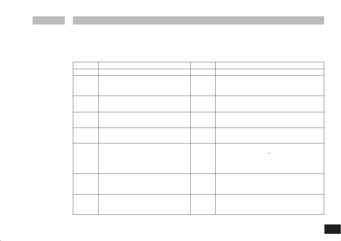
Eine Störung während des Betriebes wird durch eine Fehlermeldung im Display (E und F) angezeigt.
Gehen Sie dann wie folgt vor:
+ Gerät am Geräteschalter (A) ausschalten
+ Korrekturmaßnahmen treffen
+ Gerät erneut starten
Lässt sich der Fehler durch die beschriebenen Maßnahmen nicht beseitigen oder wird ein anderer Fehlercode angezeigt
- wenden Sie sich bitte an die Serviceabteilung,
- senden Sie das Gerät mit e
iner kurzen Fehlerbeschreibung ein.
Fehlercodes
Fehlercode Ursache Folge Korrektur
E3 Geräteinnentemperatur zu hoch Heizung aus - Gerät ausschalten und abkühlen lassen
E4 Motor blockiert Heizung aus - Gerät ausschalten
Motor aus - Achtung! Nur für autorisiertes Servicepersonal:
Steckverbindung des Motors im Geräteinneren überprüfen
E6 Unterbrechung im Sicherheitskreis Heizung aus - Kontaktstecker (L) stecken
- Kontaktthermometer PT 1000/ Temperaturfühler stecken
- Defekte Verbindungskabel, Stecker oder Kontaktthermometer
austauschen
E24 O
berflächentemperatur
(Temperatur des Regelfühlers)
: Heizung aus - Gerät ausschalten, bis die Oberflächentemperatur der Aufstell-
der Aufstellplatte ist höher als die eingestellte Sicher- platte niedriger ist als die eingestellte Sicherheitstemperatur-
heitstemperaturgrenze grenze
- Sicherheitstemperaturgrenze höher einstellen
E44 Oberflächentemperatur
(Temperatur des Sicherheitsfühlers)
: Heizung aus - Gerät ausschalten, bis die Oberflächentemperatur der Aufstell-
der Aufstellplatte ist höher als die eingestellte Sicher- platte niedriger ist als die eingestellte Sicherheitstemperatur-
heitstemperaturgrenze grenze
- Sicherheitstemperaturgrenze höher einstellen
E25 Heizung- Schaltelementüberwachung Heizung aus - Gerät ausschalten
- Sicherheitstemperaturgrenze >
55 °C wählen,
siehe auch Funktionstest “Sicherheitskreisabschaltung”
- Achtung! Nur für autorisiertes Servicepersonal:
Steckverbindung des Heizelements im Geräteinneren überprüfen
E26 Differenz Fühler Sicherheitstemperatur zu Fühler Regel- Heizung aus - Gerät ausschalten
temperatur - Achtung! Nur für autorisiertes Servicepersonal:
Regeltemperatur > (Sicherheitstemperatur + 40 K) Steckverbindung der Temperaturfühler im Geräteinneren überprüfen
E46 Differenz Fühler Sicherheitstemperatur zu Fühler Regel- Heizung aus - Gerät ausschalten
temperatur - Achtung! Nur für autorisiertes Servicepersonal:
S
icherheitstemperatur > (Regeltemperatur + 40 K) Steckverbindung der Temperaturfühler im Geräteinneren überprüfen

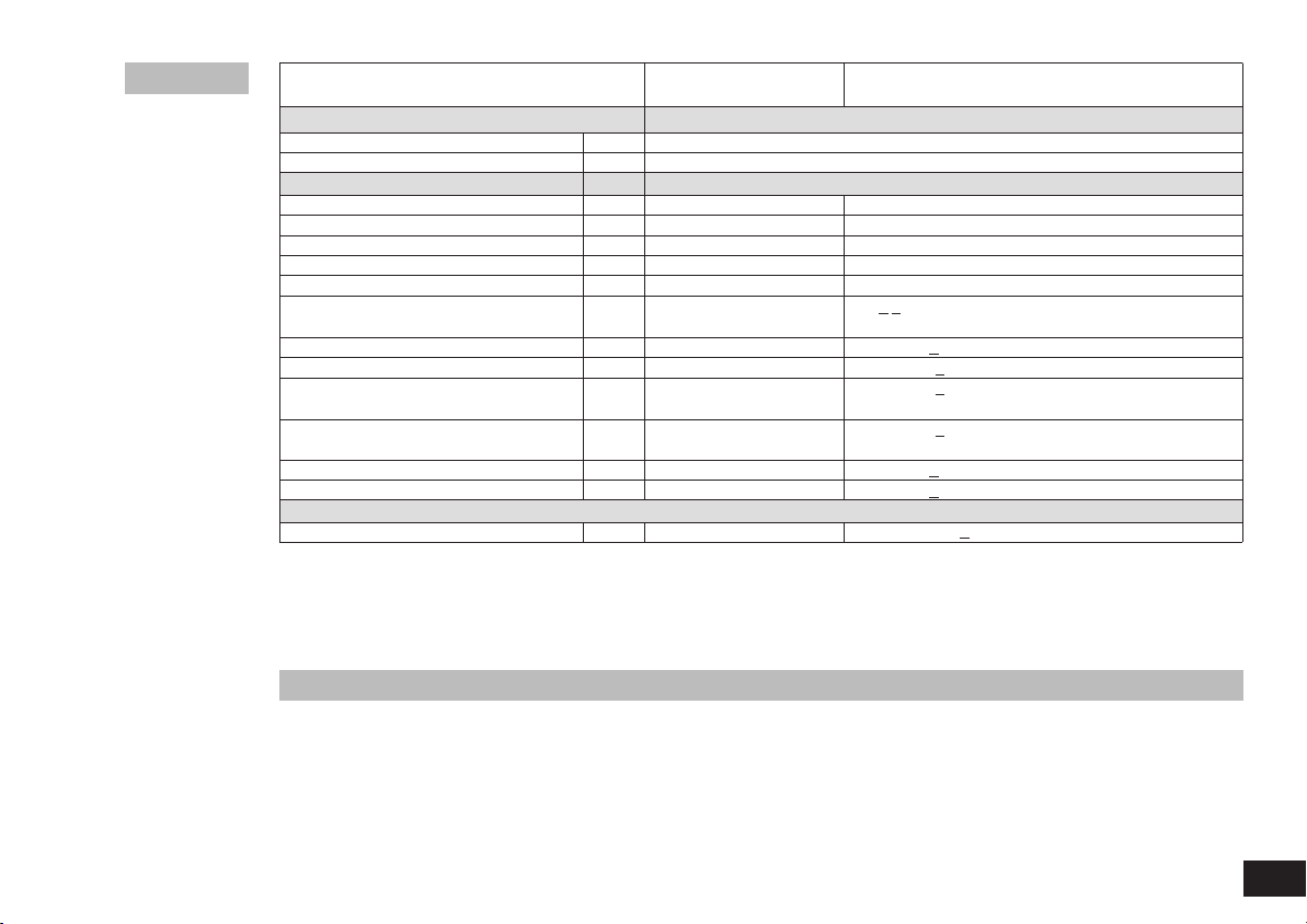
REO basic RET basic safety control
Gerät
Betriebsspannungsbereich Vac 220 - 230 +
10%
Vac 115 +
10%
Vac 100 +
10%
Nennspannung Vac 230/ 50 Hz
Vac 115/ 60 Hz
Vac 100/ 60 Hz
Frequenz Hz 50 / 60
Leistungsaufnahme (+10%) max. bei 230 Vac
W 10 630
115 Vac
10 630
100 Vac
10 455
Anzeige digital
Zul. Einschaltdauer % 100
Zul. Umgebungstemperatur °C +5 bis +40
Zul. relative Feuchte % 80
Schutzart nach DIN EN 60529 IP 42
Schutzklasse I
Überspannungskategorie II
Verschmutzungsgrad 2
Sicherungen F1/F2 T6,3A/250V (bei Nennspannung 230 V)
T10A/250V (bei Nennspannung 115 V und 100 V)
Geräteeinsatz über NN m max. 2000
Abmessung (B x T x H) mm 165 x 275 x 80 165
x
275 x 94
Gewicht kg 2,5
Motor
Drehzahlbereich rpm 50 - 1700
Nennleistungs
aufnahme W 16
Einstellauflösung rpm 10
Drehzahlabweichung (ohne Last, Nenn- %+
2
spannung, 1700 rpm, Raumtemp. 25 °C)
Max. Rührmenge (bez. auf Wasser) ltr 20
Technische Daten
12
092008
Die Gewährleistung erstreckt sich nicht auf Verschleißteile und
gilt nicht für Fehler, die auf unsachgemäße Handhabung und unzu-
reichende Pflege und Wartung, entgegen den Anweisungen in
dieser Betriebsanleitung, zurückzuführen sind.
13
092008
REO basic RET basic safety control
Aufstellplatte
Abmessung mm ø 135
Material Edelstahl
Heizen
Heizleistung
(-5%/+10%)
bei 230 V W 600
Heizleistung
(-5%/+10%)
bei 115 V W 600
Heizleistung
(-5%/+10%)
bei 100 V W 450
Einstell- und Anzeigeauflösung K1
Oberflächentemperatur °C Raumtemperatur - 340
Abweichung Temperaturmessfühler PT 1000 K<+ (0,15 +0,002
xITI)
DIN EN 60751 Kl. A
Max. Temperaturabweichung bei 100 °C K+1,5
Abweichung der Heizplattentemperatur K+
5
Regelhysterese Heizplatte, K+
5
ohne Gefäß, Heizplattenmitte bei 100 °C
Regelhysterese mit K+
1
Temperaturmessfühler PT 1000*
mit ETS-D5* °C +
0,5
mit ETS-D6* °C +
0,2
Einstellbarer Sicherheitskreis
Sicherheitstemperaturgrenze (einstellbar) °C 50 - 360 (+
10)
* Die angegebene Regelgenauigkeit wurde für folgende Werte ermittelt: 500 ml Wasser im 600 ml-Becherglas , Rührstab 40, 600 rpm, 50 °C
Technische Änderung vorbehalten!
Entsprechend den IKA-Verkaufs-und Lieferbedingungen beträgt
die Gewährleistungszeit 24 Monate. Im Gewährleistungsfall wen-
den Sie sich bitte an Ihren Fachhändler, oder senden Sie das
Gerät unter Beifügung der Lieferrechnung und Nennung der Re-
klamationsgründe direkt an unser Werk. Frachtkosten gehen zu
Ihren Lasten.
Gewährleistung
Page
CE - Declaration of conformity 14
Safety instructions 14
Unpacking 16
Correct use 16
Operation 17
Setting the operating mode 18
Setting the safety temperature limit for 18
RET basic safety control
Setting the temperature control mode for 19
RET basic safety control
Assembling the stand 19
Maintenance 20
Accessories 20
Error codes 21
Technical data 22
Warranty 23
We declare under our sole responsibility that this product is i
n
compliance with the regulations 2006/95/EC and 2004/108/EC
and conforms to the standards or standardized documents DIN EN
IEC 61010-1, -2-010 and DIN EN IEC 61326-1.
For your protection
• Read the operating instructions in full before starting up and
follow the safety instructions.
• Keep the operating instructions in a place where they can be
accessed by everyone.
• Ensure that only trained staff work with the appliance.
• Follow the safety instructions, guidelines, occupational health
and safety and accident prevention regulations.
• Socket must be earthed (protective ground contact).
• Caution - Magnetism! Effects of the magnetic field have to be
taken into account (e.g. data storage media, cardiac pacemakers ...).
•
Risk of burns! Exercise caution when touching the housing parts and
the heating plate. The heating plate can reach temperatures in excess
of 340 °C. Pay attention to the residual heat after switching off.
• Ensure that the mains power supply cable does not touch the
heating base p
late.
• Wear your personal protective equipment in accordance with the
hazard category of the media to be processed. Otherwise there
is a risk from:
- splashing and evaporation of liquids
- ejection of parts
- release of toxic or combustable gases.
• Set up the appliance in a spacious area on an even, stable, clean,
non-slip, dry and fireproof surface.
• The feet of the appliance must be clean and undamaged.
• C
heck the appliance and accessories beforehand for damage
each time you use them. Do not use damaged components.
• Gradually increase the speed.
• Reduce the speed if
- the medium splashes out of the vessel because the speed is too high
- the appliance is not running smoothly
- the container moves on the base plate.
• Caution! Only process and heat up any media that has a flash
point higher than the adjusted safe temperature limit that has
been set (50 to 360 °C).
Contents
CE-Declaration of conformity
14
032010
EN
Safety instructions
15
092008
The safe temperature limit must always be set to at least 25 °C
lower than the fire point of the media used.
• Beware of hazards due to:
- flammable materials
- combustible media with a low boiling temperature
- glass breakage
- incorrect container size
- overfilling of media
- unsafe condition of container.
• The appliance may heat up when in use.
• The base plate can heat up due to the action of the drive magnets
at high motor speeds, even if the heater is not operational.
• Process pathogenic materials only in closed vessels under a suit-
able extractor hood. Please contact IKA if you have any questions.
• D
o not operate the appliance in explosive atmospheres, with
hazardous substances or under water.
• Only process media that will not react dangerously to the extra
energy produced through processing. This also a
pplies to any
extra energy produced in other ways, e.g. through light irradiation.
• Please observe the operating instructions for any accessories used.
• Ensure that the external temperature sensor (PT 1000, ETS-D ...)
is inserted in the media to a depth of at least 20 mm.
• The PT 1000 external temperature sensor must always be inser-
ted in the media when connected.
• Safe operation is only guaranteed w
ith the accessories described
in the ”Accessories” chapter.
• Accessories must be securely attached to the device and cannot
come off by themselves. The centre of gravity of the assembly
must lie within the surface on which it is set up.
• Always disconnect the plug before fitting accessories.
• The appliance can only be disconnected from the mains supply
by pulling out the mains plug or the connector plug.
• The socket for the mains cord must be easily accessible.
• The device will automatically restart in mode B following any
interruption to the power supply.
• It may be possible for wear debris from rotating accessory parts
to reach the material being processed.
• When using PTFE-coated magnetic bars, the following hase to
be noted: Chemical reactions of PTFE occur in contact with mol-
ten or solute alkali metals and alkaline earth metals, as well as
with fine powders of metals in groups 2 and 3 of the periodic
system at temperatures above 300 °C - 400 °C. Only elementa-
ry fluorine, chlorotrifluoride and alkali metals attack it; halogena-
ted hydrocarbons have a r
eversible swelling effect.
(Source: Römpps Chemie-Lexikon and ”Ulmann”, Volume 19)
For protection of the equipment
• The appliance may only be opened by experts.
• The voltage stated on the type plate must correspond to the mains
voltage.
• Do not cover the device, even partially e.g. with metallic plates
or film. This results in overheating.
• Ensure that the base plate is kept clean.
• Protect the appliance and accessories from bumps and impacts.
• Observe the minimum distances between the devices, between
the device and t
he wall and above the assembly (min. 800 mm),
see fig. 3.
> 100 mm > 100 mm
> 100 mm
Fig. 3

•
Unpacking
- Please unpack the device carefully
- In the case of any damage a detailed report must be set imme-
diately (post, rail or forwarder)
•
Contents of package
REO basic RET basic safety control
- Magnetic stirrer - Heating magnetic stirrer
- Mains cable - Mains cable
- Operating instructions - Operating instructions
- Protection cover - Screwdriver
- Temperature sensor PT 1000
- Protection cover
•
Use
- For mixing and/or heating liquids
•
Range of use
- Laboratories - Schools
- Pharmacies - Universities
This device is suitable for use in all areas except industrial areas.
The safety of the user cannot be guaranteed if the appliance is
operated with accessories that are not supplied or recommended
by the manufacturer or if the appliance is operated improperly con-
trary to the manufacturer’s specifications or if t
he appliance or the
printed circuit board are modified by third parties.
16
092008
Unpacking Correct use
17
092008
Commissioning
Stirring
Heating
Connecting
external
thermometers
(direct temper-
ature control in
the medi
a)
REO basic RET basic safety control
+
Move device switch (A) to the OFF position
+ Insert the mains power cable into the power socket (K)
+ Move device switch (A) to the ON position
„ Operating mode B is preset
„ Operating mode A is preset (see “Operating modes”)
Operation
+ Adjust the motor speed using the rotary knob (D)
„ The value selected will be shown on the display (F)
+ Set the start point for the agitation function by pressing the rotary knob (D)
„ The displayed value will flash until the desired motor speed is reached
i
Ensure that the protective film is removed from the base plate before use!
+ Move device switch (A) to the OFF position
+ Detach contact plug (L)
+ Attach a DIN 12878 (Class 2) compliant safety contact thermometer or a
PT 1000 temperature sensor to the socket (L)
+ Move device switch (A) to the ON position
Temperature sensor PT 1000
„ The actual temperature for the temperature sensor shown on
display (E) will correspond to the temperature of the media.
The LED "external temp
erature s
ensor" (H) will be lit
Contact thermometer e.g. ETS-D5
„
Follow the operating instructions for the contact thermometer
The LED "decimal point for the temperature display" (J) will be lit
When a contact thermometer is connected, the display (E)
will only show the set-point temperature that has been set
i
i
+ Set the safe temperature limit (see "Setting the safe temperature limit for RET")
+
Adjust the set-point temperature using the rotary knob (C)
„ The value selected will be shown on the display (E)
+
Set the temperature control mode
(see “Setting the temperature control mode for RET”)
+ Set the start point for the heating function by pressing the rotary knob (C)
The set-point and actual temperatures will be s
hown alternately on the display (E)
„ When the heating is switched on, the LED “Heating plate” (G) and the LED “Set-point value” (I)
will be lit.
„ During agitation and standby operation, the display (E) will show if the base plate temperatu
re is above 50 °C.
HOt
The maximum temperature that can be set for the heating plate is 340 °C
i
i

18
092008
The safe temperature limit that has been set
will be displayed when the device is switched
on.
Factory setting: 360 °C
Adjustment range: > 50 - 360 °C
Setting the safe temperature limit
The temperature set for the heating plate (maximum 340 °C) will
be at least 10 °C lower than the safe temperature limit.
Warning: The safe temperature limit must always be set at
least 25 °C lower than the flash point of the m
edia to be pro-
cessed.
Functional check of inactivating the safety circuit
RET basic safety control
Operating the device in mode A or B
Mode A
All settings will be stored if the device is switched off or discon-
nected from the power supply. The agitation and heating functions
will be set to OFF when the device is powered on.
Mode B
All settings will be stored if the device is switched off or discon-
nected from the power supply. The agitation and heating functions
will be set to ON or OFF when the device is powered on, depen-
ding on the previous status of the device.
Factory setting: mode A
The mode selected will be shown on the dis-
play when the device is started up.
Change the mode
REO basic
Operating the device in the preset mode
The operating mode is preset and not changeable.
Description of the mode and the display see RET
Factory setting REO basic: mode B
Setting operating mode
xx A
(x: software version)
mode
+ Move device switch (A) to the OFF position
+ Press and hold rotary knobs (C and D)
+ Move device switch (A) to the ON position
+ Release rotating knobs (C and D)
„ The set value is indicated on the display (F)
Setting the safe temperature limit for
RET basic safety control
360 SAFE
i
xx A
Fig. 5
+ Move device switch (A) to the ON position
+ The safe temperature limit can be adjusted using a screwdriver
„ The set value is indicated on the display (F)
150 SAFE
i
+ Position the safe temperature limit at the left (50 °C)
+ Move device switch (A) to the ON position
„
Indication on the
display (F)
i
Err 25

19
092008
Assembling the stand
+ Remove screw plugs (M)
+ Remove the protective cap from the support rod
+ Put the washer between housing and nut
+ Screw the support rod onto the device by hand until the end
stop is reached
+ Use an A/f 17 spanner to tighten the M10 nut
+ Accessories should be attached using cross sleeves
Fig. 6
Note: For bath attachments with diameters
greater than ø 180 mm only use the support
rod H 16 V with the extension H 16.1.
When using an external PT1000 temperature sensor, the user can
choose between two types of control:
PI mode
Good control results, minimised overshooting, slow rise in tempe-
rature.
2P mod (two-point controller)
Maximum heating rate, increased overshooting
Factory setting: PI mode
Changing the temperature control mode
1. Set target temperature to 2 °C
2. Switch off device
3. Hold down temp knob
4. Switch on device
This activates or deactivates the two-point controller (2P) for the
external PT 1000 temperature sensor (2P appears on the display).
When switching on the device, 2P is also displayed next to the
operating mode A/B when the two-point controller is activated.
When the heating function is active in 2P mode, (with external PT
1000 temperature sensor) the actual temperature flashes - that
notifies the user that the process temperature has been greatly
overshot!
Setting temperature control mode for
RET basic safety control

20
092008
The device is maintenance-free.
Cleaning
For cleaning disconnect the main plug.
Only use cleansing agents which have been recommended by IKA.
Use to remove:
Dyes isopropyl alcohol
Construction materials isopropyl alcohol/water containing surfactant
Cosmetics isopropyl alcohol/water containing surfactant
Foodstuffs water containing surfactant
Fuels water containing surfactant
- Do not allow moisture to get into the appliance when cleaning.
- Wear protective gloves w
hen cleaning the devices.
- Please consult with IKA before using any cleaning or deconta-
mination methods, other than those recommended here.
Ordering spare
parts
When ordering spare parts, please give:
- Machine type
- Manufacturing number, see type plate
- Item number and designation of the spare part,
see www.ika.net.
Repair
The device must be clean and free from any materials which may
constitute a health hazard when sent for repair.
Please return the appliance in its original packaging. Storage pak-
kaging is not sufficient for returns. Please also use suitable packa-
ging for transportation.
• Stirring bars: ø 6 mm, length upto 15 mm
ø 7 mm, length upto 60 mm
ø 10 mm, length upto 80 mm
• RS 1 Set of magnetic stirring bars
• RSE Stirring bar remover
• H 15 Bath attachment
• H 28 Bath attachment
• H 29 Oil bath attachment
• H 30 Oil bath attachment
• H 16 V Support rod
• H 16.1 Extension
• H 38 Holding rod
• H 44 Cross sleeve
• ETS-D5 Contact thermometer
• ETS-D6 Contact thermometer
Accessories
Maintenance
21
092008
Any malfunctions during operation will be identified by an error message on the display (E and F).
Proceed as follows in such cases:
+ Switch off device using the main switch (A)
+ Carry out corrective measures
+ Restart device
If the actions described fail to resolve the fault or another error code is displayed then take one of the following steps:
- Contact the service department,
- Send the device for repair, i
ncluding a short description of the fault.
Error codes
Error code Cause Effect Solution
E3 Temperature inside device too high Heating off - Switch off device and allow to cool down
E4 Motor blockage Heating off - Switch off device
Motor off - Warning! Only to be carried out by authorised service personnel:
Carry out an internal test on the device to check the plug-in
connector for the motor
E6 Break in safety circuit Heating off - Plug in contact plug (L)
- Plug in PT 1000 contact thermometer/temperature sensor
- Replace faulty connecting cable, plug, or contact thermometer
E24 S
urface temperature (temperature of control sensor): Heating off - Switch off device until the surface temperature of the base plate
of the base plate is higher than the setted safe tem- is lower than the selected safe temperature limit
perature limit - Set a higher safe temperature limit
E44 Surface t
emperature (temperature of safety sensor): Heating off - Switch off device until the surface temperature of the base plate
of the base plate is higher than the setted safe tem- is lower than the selected safe temperature limit
perature limit - Set a higher safe temperature limit
E25 Heating and switching element monitoring Heating off - Switch off device
- Set the safe temperature limit >
55 °C,
see also “Functional check of inactivating the safety circuit”
- Warning! Only to be carried out by authorised service personnel:
Carry out an internal test on the device to check the plug-in connector.
for the heating element
E26 Difference between temperature of safety sensor and Heating off - Switch off device
temperature of control sensor - Warning! Only to be carried out by authorised service personnel:
control temperature > (safety temperature + 40 K) Carry out an internal test on the device to check the plug-in
connector for the temperature sensor
E46 Difference between temperature of safety sensor and Heating off - Switch off device
temperature of control sensor - Warning! Only to be carried out by authorised service personnel:
safety temperature > (control temperature + 40 K) Carry out an internal test on the device to check the plug-in
connector for the temperature sensor
 Loading...