


30 830 01 a |
,.$â WERKE |
,.$® Calorimeter System C 2000 EDVLF
C 2000 FRQWURO
23(5$7,1* ,16758&7,216 (1
86$
 Vers. 04 08.07
  Reg.-No. 4343-01
&( ± .21)250,7b76(5./b581* |
'( |
Wir erklären in alleiniger Verantwortung, dass dieses Produkt den Bestimmungen der Richtlinien 89 / 336 / EG und 2006 / 95 EG entspricht und mit folgenden Normen und normativen Dokumenten übereinstimmt: DIN EN IEC 61 010-1 und DIN EN IEC 61 326-1.
&( ± '(&/$5$7,21 2) &21),50,7< |
(1 |
We declare under our sole responsibility that this product corresponds to the regulations 89 / 336 / EEC and 2006 / 95 EEC and conforms with the standards or standardized documents: DIN EN IEC 61 010-1 and DIN EN IEC 61 326-1.
'e&/$5$7,21 '( &21)250,7e &( |
)5 |
Nous déclarons sous notre responsabilité que se prodiut est conforme aux réglementations 89 / 336 / CEE et 2006 / 95 CEE et en conformité avec les normes ou documents normalisés suivant: DIN EN IEC 61 010-1 et DIN EN IEC 61 326-1.
'(&/$5$&,21 '( &21)250,'$' '( &( |
(6 |
Declaramos por nuestra responsabilidad propia que este producto corresponde a
las directrices 89 / 336 / CEE y 2006 / 95 CEE y que cumple las normas o documentos normativos siguientes: DIN EN IEC 61 010-1 y DIN EN IEC 61 326-1.
&( ± ',&+,$5$=,21( ', &21)250,7¬ |
,7 |
Dichiariamo, assumendone la piena responsabilità, che il prodotto è conforme alle seguenti direttive 89 / 336 / CCE e 2006 / 95 CCE, in accordo ai seguenti regolamenti e documenti: DIN EN IEC 61 010-1 e DIN EN IEC 61 326-1.
IKAâ-WERKE C 2000 basic / control |
Ver. 04 08.07 |

([SODQDWLRQ RI V\PEROV
ThisKHDOWKsymbolDQG VDIHW\identifies information WKDW LV RI DEVROXWH LPSRUWDQFH WR HQVXUH \RXU
Failure to observe this information may be detrimental to your health or may result in injuries.
This symbol identifies information WKDW LV RI LPSRUWDQW WR HQVXUH SUREOHP IUHH WHFKQLFDO RSHUDWLRQ RI WKH GHYLFH Failure to observe this information may result in
damage to the calorimeter system.
This symbol identifies information that is important to ensure problem-free operation of calorimetric measurements and for working with the calorimeter system. Failure to observe this information may result in inaccurate measurement results.
IKAâ-WERKE C 2000 basic / control |
Ver. 04 08.07 |

3DJH ,
&RQWHQWV
3DJH
)RU \RXU VDIHW\
8VHU QRWHV
2.1 |
User notes on the Operating Instructions ....................................... |
2-1 |
2.2 |
Warranty ....................................................................................... |
2-1 |
2.3 |
Warranty claims and liability .......................................................... |
2-2 |
2.4 |
System properties ......................................................................... |
2-2 |
7UDQVSRUWDWLRQ VWRUDJH DQG VHW XS ORFDWLRQ
3.1 |
Transportation and storage requirements ....................................... |
3-1 |
3.2 |
Set-up location .............................................................................. |
3-1 |
3.3 |
Unpacking..................................................................................... |
3-2 |
3.4 |
Scope of delivery .......................................................................... |
3-2 |
'HVFULSWLRQ RI WKH V\VWHP FRPSRQHQWV
4.1 |
C 2000 |
EDVLF ................................................................................. |
4-1 |
4.2 |
C 2000 |
FRQWURO .............................................................................. |
4-3 |
4.3 |
Cooling |
......................................................................................... |
4-4 |
&DORULPHWULF PHDVXUHPHQWV
5.1 |
Determination of gross calorific value ............................................ |
5-1 |
5.2 |
Corrections ................................................................................... |
5-2 |
5.3 |
Complete combustion .................................................................... |
5-3 |
5.4 |
Calibration .................................................................................... |
5-4 |
6HW XS DQG FRPPLVVLRQLQJ
6.1 |
Set-up........................................................................................... |
6-1 |
6.2 |
Connection oxygen supply ............................................................. |
6-4 |
6.3 |
Connecting peripheral devices ....................................................... |
6-5 |
6.4 |
Display and operating elements ..................................................... |
6-6 |
6.5 |
Turning on the system ................................................................... |
6-9 |
6.6 |
Configuring the system ................................................................ |
6-12 |
6.7 |
Turning off the system ................................................................. |
6-19 |
IKAâ-WERKE C 2000 basic / control |
Ver. 03 03.04 |

|
&RQWHQWV |
3DJH , |
|
|
|
3UHSDULQJ DQG SHUIRUPLQJ PHDVXUHPHQWV
7.1 |
Notes on calibration ...................................................................... |
7-1 |
7.2 |
Notes on the sample ..................................................................... |
7-2 |
7.3 |
Preparing the measurement........................................................... |
7-4 |
7.4 |
Performing the measurement......................................................... |
7-8 |
7.5 |
Cleaning the decomposition vessel .............................................. |
7-11 |
(YDOXDWLQJ FDOLEUDWLRQV
(YDOXDWLRQ RI JURVV FDORULILF YDOXH GHWHUPLQDWLRQV
9.1 |
Post-processing experiments ......................................................... |
9-1 |
9.2 |
Calculating reference states / experiment evaluation ...................... |
9-4 |
([SHULPHQW VLPXODWLRQ
&DUH DQG PDLQWHQDQFH
11.1 |
Maintenance menu ...................................................................... |
11-1 |
|
11.2 |
Inner vessel sieve ....................................................................... |
11-2 |
|
11.3 |
Dirt trap in the water supply line .................................................. |
11-2 |
|
11.4 |
Maintenance for the water circuit ................................................. |
11-3 |
|
11.5 |
Changing the O2 |
seal .................................................................. |
11-5 |
11.6 |
Changing the O2 |
filling piston....................................................... |
11-5 |
11.7 |
Decomposition vessels ................................................................ |
11-6 |
|
11.8 |
Notes on cleaning ....................................................................... |
11-6 |
|
7URXEOHVKRRWLQJ
12.1 |
Malfunction with message in the display ...................................... |
12-1 |
12.2 |
Malfunction without message in the display.................................. |
12-5 |
$FFHVVRULHV DQG FRQVXPDEOHV
13.1 |
Accessories ................................................................................ |
13-1 |
13.2 |
Consumables .............................................................................. |
13-1 |
7HFKQLFDO GDWD
,QGH[
IKAâ-WERKE C 2000 basic / control |
Ver. 03 03.04 |

3DJH
)RU \RXU VDIHW\
LQWHQGHG SXU
SRVH
RSHUDWLQJ
UHTXLUHPHQWV
H[SORVLYH
VXEVWDQFHV
QRWHV RQ WKH
VDPSOH
FRPEXVWLRQ
UHVLGXH
DX[LOLDU\
PDWHULDOV
In order to be able to use the appliance properly and safely, every user must first read the operating instructions and observe the safety instructions contained therein. Take care of these operating instructions and keep them in a place where they can be accessed by everyone.
The C 2000 calorimeter system may only be used to determine the gross calorific value of solid and liquid materials materials in accordance with DIN 51900, BS 1016 T5, ISO 1928, ASTM 5468, ASTM 5865 and ASTM 4809. For this purpose, use only original IKAâ decomposition vessels C 5010, C 5012 and C 62. For further details please see the operating instructions of the decomposition vessels C 5010, 5012 and C 62.
The maximum amount of energy input into the decomposition vessel must not exceed -. (Select the weight of the sample accordingly). The permissible operating pressure of EDU 0SD must not be exceeded. The maximum permissible operating temperature must not exceed ƒ&.
Do not fill the decomposition vessel too full of the sample. Only fill the decomposition vessel with oxygen up to a maximum pressure of EDU 0SD . Monitor the adjusted pressure on the pressure reducer of your oxygen supply. Perform a leakage test before every combustion (please observe the operating instructions of the decomposition vessels C 5010, C 5012 and C 62, chapter ”Leakage test”).
Many substances tend to combust in an explosive manner (for example because of
the formation of peroxide). This may cause the decomposition vessel to burst.
7KH VWDQGDUG GHFRPSRVLWLRQ YHVVHOV PXVW QRW EH XVHG IRU H[DPLQDWLRQV RQ VDPSOHV WKDW DUH FDSDEOH RI H[SORGLQJ ,W LV DEVROXWHO\ HVVHQWLDO WR XVH D VSH FLDO KLJK SUHVVXUH GHFRPSRVLWLRQ YHVVHO WR FRQWDLQ WKH VDPSOH LQ WKHVH FDVHV
Substances of which the combustion behavior is not known must be examined for
their combustion behavior before combustion in the decomposition vessel C 5010, C 5012 or C 62 (danger of explosion). If you are burning XQNQRZQ VDPSOHV, leave the room or NHHS D VDIH GLVWDQFH between you and the calorimeter.
Benzoic acid must only be burned in the form of pellets! Combustible dust and powder must be compressed into pellets before combustion. Oven-dry dust and powder such as wood chips, hay, straw, etc. burn in an explosive manner! They must be moistened first! Readily combustible liquids with a low vapor pressure must not be come in direct contact with the cotton thread (for example tetramethyl dihydrogen disiloxan)!
In addition, toxic residues of combustion are possible in the form of gasses, ash or precipitates on the inner wall of the decomposition vessel, for example.
2EVHUYH WKH DFFLGHQW SUHYHQWLRQ UHTXLUHPHQWV DSSOLFDEOH WR WKH DFWLYLW\ DQG WKH ZRUN VWDWLRQ :HDU SHUVRQDO VDIHW\ HTXLSPHQW
When handling combustion samples, combustion residues and auxiliary materials, the appropriate safety requirements must be observed. The following are examples of substances that may cause dangers:
–corrosive
–easily flammable
–capable of exploding
–contaminated with bacteria
–toxic
IKAâ-WERKE C 2000 basic / control |
Ver. 04 08.07 |

3DJH
R[\JHQ
)RU \RXU VDIHW\
When working with oxygen, observe the appropriate requirements.
Danger warning: As a compressed gas, oxygen promotes combustion, supports
combustion intensively and may react violently with combustible substances.
'R QRW XVH DQ\ RLO RU JUHDVH
Keep all gas lines and screw connections that carry oxygen free from grease. Observe the accident prevention requirements applicable to the activity and the work station.
Close the main valve on the oxygen supply when work is complete. Only carry out maintenance work when the system is depressurised.
XVLQJ D FUXFLEOH
PDGH RI VWDLQ OHVV VWHHO
When using crucibles made of stainless steel, their condition should be carefully checked after every experiment.
A reduction in the thickness of the material may cause the crucible to burn and may damage the decomposition vessel. For reasons of safety, crucibles must not be used any more after a maximum of 25 combustion procedures.
VSHFLILFDWLRQ RI
WKH GHFRPSRVL WLRQ YHVVHO
UHSHDWHG WHVWV
The decomposition vessel is manufactured in accordance with the regulation for pressure vessels 97/ 23/ EEC. This can be recognized from the &( V\PERO with the
identifying number of the testing station named. The decomposition vessel is a pressure device of Category III. The decomposition vessel has been subjected to an EC prototype test. The CE declaration of conformity represents our guarantee to you that this decomposition vessel complies with the pressure device described in the EC prototype test certificate. The decomposition vessel has been subjected to a
pressure test at a test pressure of EDU and a leakage test with oxygen at 30 bar. Decomposition vessels are H[SHULPHQW DXWRFODYHV and must be tested by a SUR IHVVLRQDOO\ WUDLQHG SHUVRQ each time before they are used.
An individual application is understood here to mean a series of experiments that are performed under roughly the same conditions in terms of pressure and temperature Experiment autoclaves must be operated in special chambers (C 2000, C 5000).
The decomposition vessel must be subject to repeated tests (internal tests and pressure tests) by a SHUVRQ ZLWK SURIHVVLRQDO WUDLQLQJ. The intervals between
tests must be determined by the operator based on experience, operating manner
and the material used in the decomposition vessel.
7KH GHFODUDWLRQ RI FRQIRUPLW\ ORVHV LWV YDOLGLW\ LI PHFKDQLFDO PRGLILFDWLRQV DUH PDGH WR WKH H[SHULPHQW DXWRFODYHV RU LI VWDELOLW\ FDQ QR ORQJHU EH JXDUDQWHHG DV D UHVXOW RI KHDY\ FRUURVLRQ IRU H[DPSOH KROHV HDWHQ LQ LW E\ KDORJHQV
The WKUHDGLQJ on the body of the decomposition vessel and cap screw in particular are subject to a high level of mechanical stress and must therefore be monitored regularly for wear and tear.
The condition of the seals must be checked for functionality and must be ensured by means of a leakage test (please observe the operating instructions of the decomposition vessels C 5010, C 5012 and C 62, chapter “Leakage testº).
Pressure tests and service tasks on the decomposition vessel must only be performed by SHUVRQV ZLWK SURIHVVLRQDO WUDLQLQJ.
:H UHFRPPHQG WKDW WKH GHFRPSRVLWLRQ YHVVHO EH VHQW LQWR RXU IDFWRU\ IRU LQ VSHFWLRQ DQG UHSDLUV LI QHFHVVDU\ DIWHU HLWKHU H[SHULPHQWV RU DIWHU RQH \HDU RU GHSHQGLQJ RQ WKH DSSOLFDWLRQ HYHQ VRRQHU WKDQ WKLV
IKAâ-WERKE C 2000 basic / control |
Ver. 04 08.07 |

GHILQLWLRQ RI
SHUVRQ ZLWK SURIHVVLRQDO WUDLQLQJ
RSHUDWLQJ SUHV
VXUH FRQWDLQHUV
3DJH
A person with professional training as defined in these operating instructions is someone
1.whose training, knowledge and experience gained through practical activities ensures that that person will perform the tests in a proper manner.
2.who is sufficiently reliable
3.who is not subject to any instructions in terms of testing activity
4.who is equipped with suitable testing equipment if necessary
5.who can provide suitable proof demonstrating compliance with the requirements listed in 1.
National regulations and laws for operating pressure containers must be observed! Anyone who operates a pressure container must maintain it in proper condition, must monitor it and perform necessary maintenance and repair tasks without delay,
and must take measures appropriate for the circumstances to ensure safety. $ SUHVVXUH FRQWDLQHU PXVW QRW EH RSHUDWHG LI LW H[KLELWV GHIHFWV WKDW FRXOG HQ GDQJHU WKRVH ZRUNLQJ ZLWK LW RU WKLUG SDUWLHV You can obtain a copy of the pres-
sure vessel regulation from Carl Heymann Verlag or Beuth Verlag.
IKAâ-WERKE C 2000 basic / control |
Ver. 04 08.07 |
IKAâ-WERKE C 2000 basic / control |
Ver. 04 08.07 |
3DJH
8VHU QRWHV
ZRUN WKURXJK
&KDSWHUV
8VHU QRWHV RQ WKH 2SHUDWLQJ ,QVWUXFWLRQV
In this chapter you can find out how to work through these Operating Instructions most effectively to be able to work reliably with the calorimeter system.
<RX PXVW IROORZ WKH LQVWUXFWLRQV LQ &KDSWHU ³)RU <RXU 6DIHW\´
Chapters 1 through 12 are designed for you to work through them in order.
Chapter 3, “Transportation, storage and set-up location” is relevant for the reliability of the system and to ensure a high degree of accuracy in measurements. Chapter 4 describes the system components and Chapter 5 contains the basic principles of calorimetry.
SHUIRUPLQJ DQ
H[SHULPHQW
The calorimeter system is ready to conduct measurements as soon as you have performed the procedures in Chapter 6 “Set-up and commissioning“ and Chapter 7 “Preparing and performing measurements“.
Evaluation of calibrations is described in Chapter 8.
Chapter 9 describes how to evaluate determinations of gross calorific value and how to calculate reference states. Chapter 10 explains the option of simulating experiments with the calorimeter system. In Chapter 11 you will find some important notes on system upkeep and maintenance. Chapter 12 contains a list of simple malfunctions and how to eliminate them.
You will find accessories, consumables and technical data on the device in Chapters 13 and 14, with the Index in Chapter 15.
The figures c, d, e etc. in the following chapters indicate actions that must always be carried out in the sequence given.
:DUUDQW\
In accordance with IKA warranty conditions, the warranty period is 12 months. For claims under the warranty please contact your local dealer. You may also send the machine direct to our works, enclosing the delivery invoice and giving reasons for the claim. You will be liable for freight costs.
The warranty does not cover wearing parts, nor does it apply to faults resulting from improper use or insufficient care and maintenance contrary to the instructions in this operating manual.
IKAâ-WERKE C 2000 basic / control |
Ver. 04 08.07 |

|
8VHU QRWHV |
3DJH |
|
|
|
:DUUDQW\ FODLPV DQG OLDELOLW\
SDUWV FRQGXFWLQJ
HOHFWULFDO SRZHU
Please read these Operating Instructions carefully and in their entirety. IKAâ will only consider itself responsible for the safety, reliability and performance of the device if
∙the device has been operated in accordance with the Operating Instructions
∙only persons authorized by the manufacturer have performed repair and maintenance work on the device
∙only original parts and original accessories have been used in repair work.
The calorimeter system may only be opened by a customer service center.
If service is required, we recommend that you contact our customer service department.
Furthermore, we refer you to the applicable safety conditions and accident requirements.
IKAâ is not responsible for damages or costs resulting from accident, improper use of the device or impermissible modifications, repairs or renovations.
6\VWHP SURSHUWLHV
The C 2000 calorimeter system is routinely used for determination of gross calorific values of solid and liquid substances. The accessories of the system ensure customized adaptation to laboratory tasks (see Chapter 13).
The system is characterized by the following features:
∙Relieves you of routine tasks through automated measurement procedure
∙Integrated oxygen filling
∙Automatic detection of decomposition vessel (DV)
∙Operation without the cooling unit: Connection to a water faucet; temperature range 12°C - 28°C; water consumption per measurement about 4 l; water pressure 1 bar to max. 1.5 bar; at higher pressures, use C 25.
∙Operation with active cooling unit (for example IKAâ KV 500, optional)
∙Measurement and calculation of gross calorific value according to DIN 51900, ISO 1928, ASTM D240, ASTM D4809, ASTM D5865, ASTM D1989, ASTM D5468, ASTM E711
∙Calculation of net calorific value according to DIN 51900, ASTM D240, ASTM D4809, ASTM D5865, ASTM D1989, ASTM D5468, ASTM E711
∙Measurement range: max. 40,000 J
(This corresponds to an increase in temperature in the inner vessel of about 5 K)
IKAâ-WERKE C 2000 basic / control |
Ver. 04 08.07 |

3DJH
∙Operating mode based on the isoperibolic or dynamic principle
At 25°C or 30°C (the beginning temperature of the water in the inner vessel) depending on the cooling water temperature (see Chapter 4.3).
Cooling water |
Operating mode |
temperature |
|
12°C to 23°C |
isoperibolic 25°C |
12°C to 23°C |
dynamic 25°C |
23°C to 28°C |
isoperibolic 30°C |
23°C to 28°C |
dynamic 30°C |
∙A monitor and external keyboard can be connected
∙PC-operation of one or several calorimeters (CalWinâ software)
∙A sample rack can be connected
∙A printer can be connected
IKAâ-WERKE C 2000 basic / control |
Ver. 04 08.07 |
IKAâ-WERKE C 2000 basic / control |
Ver. 04 08.07 |

3DJH-1
7UDQVSRUWDWLRQ VWRUDJH DQG VHW XS ORFDWLRQ
7UDQVSRUWDWLRQ DQG VWRUDJH UHTXLUHPHQWV
During transportation and storage, the system must be protected against mechanical jarring, vibrations, accumulations of dust and corrosive ambient air. Care should also be taken so that the relative humidity does not exceed 80%.
The device must be completely emptied before being stored and transported.
In case of repair the device has to be cleaned and free from any materials which may constitute a health hazard.
If you require servicing, return the appliance in its original packaging. Storage packaging is not sufficient. Please also use suitable transport packaging.
6HW XS ORFDWLRQ
When setting up the device, make certain that the applicable state regulations for operating pressurized containers are adhered to.
A constant ambient temperature is an important prerequisite in ensuring the high measurement precision of the system. The following conditions must therefore be maintained at the set-up location:
∙No direct sunlight.
∙No drafts (for example next to windows, doors, air conditioner outlets).
∙The device must be at a sufficient distance from heater and other sources of heat.
∙The minimum distance between the wall and the rear side of the device must be at least 25 cm.
∙The system must not have laboratory hardware such as shelves, wire ducts, ring lines, etc. installed above it.
∙The room temperature must be in the range of 20 °C ... 25 °C (constant).
∙The system must be set up on a horizontal surface.
A power supply corresponding to the rating plates of the system components and the oxygen supply (99.95% pure oxygen, quality 3.5; pressure 30 bar, with a pressure display) must be available to operate the system at the set-up location. A shutoff valve for the oxygen supply must be installed. Observe the instructions on handling oxygen given in Section 1 "For your safety”.
IKAâ-WERKE C 2000 basic / control |
Ver. 04 08.07 |
|
7UDQVSRUWDWLRQ VWRUDJH DQG VHW XS ORFDWLRQ |
3DJH |
|
|
|
8QSDFNLQJ
Please unpack the system components carefully and check closely for any damage. It is important to recognize any damage that occurred during shipping while you are unpacking. If damage has occurred, you will need to make a written assessment of the damage and send it to us by mail, rail or special delivery.
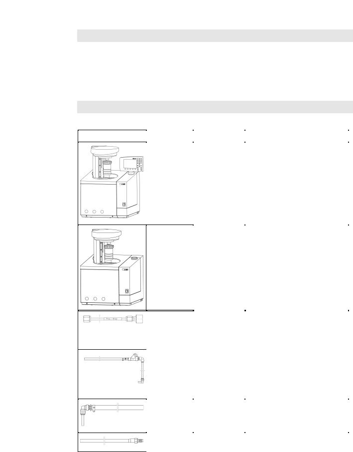
6FRSH RI GHOLYHU\
|
|
|
|
|
|
|
|
& EDVLF |
& FRQWURO |
%HVFKUHLEXQJ |
|
||
|
|
|
|
|||
|
1x |
|
|
|
Grundgerät |
|
|
|
|
|
|
Beilegeset |
|
|
|
|
|
|
Netzanschlusskabel |
|
|
|
|
|
|
Betriebsanleitung |
|
|
|
|
|
|
|
|
1x |
Grundgerät |
|
C 5040 CalWin Software |
|
Beilegeset |
|
Netzanschlusskabel |
|
Betriebsanleitung |
|
|
|
|
1x |
1x |
O2-Druckschlauch |
|
|
|
Länge: |
2 m |
|
|
Anschlüsse: 1 x M8x1, SW 10 |
|
|
|
|
1 x ¼“ , SW 17 |
|
|
|
|
1x |
1x |
Zuflussleitung Wasser |
|
|
|
Länge: 1,5 m |
|
|
|
|
|
1x |
1x |
Rückflussleitung Wasser |
|
|
Länge: 1,5 m |
|
|
|
1x |
1x |
Entleerschlauch Wasser |
|
|
Länge: 1m |
|
|
|
IKAâ-WERKE C 2000 basic / control |
Ver. 04 08.07 |

3DJH
'HVFULSWLRQ RI WKH V\VWHP FRPSRQHQWV
|
|
|
|
&EDVLF |
|
|
|
|
|
|
|
|
|
|
|
||
|
||
|
||
|
|
|
1 |
Control panel |
|
2 |
Keyboard |
|
3 |
Display |
|
4 |
Electronics unit |
|
5 |
Measuring cell |
|
6 |
Temperature sensor |
|
7 |
Oxygen filling device |
|
8 |
Decomposition vessel |
|
|
(Accessory, please |
& |
|
order seperately) |
EDVLF |
9 |
Measuring cell cover |
The control panel is the operating and display unit for the system. Commands and experiment parameters are entered in dialog mode via the keyboard; visual control takes place through the display.
All phases of the measurement procedure are controlled and monitored during an experiment The display shows the current system states and experiment data.
Any malfunctions are also displayed as a line of text.
The results of the experiment are stored together with the experiment parameters and may be printed out whenever desired.
Communication with external peripheral devices (for example printers, analytical scale, sample rack, PC, and keyboard) via the interfaces in the electronics unit is also shown on the display.
IKAâ-WERKE C 2000 basic / control |
Ver. 04 08.07 |
|
'HVFULSWLRQ RI WKH V\VWHP FRPSRQHQWV |
3DJH |
H[SHULPHQW
SURFHGXUH
The calorimetric experiment, which entails combustion of the fuel sample under precisely defined conditions, takes place in the measuring cell.
The following components are located in the measuring cell for this purpose:
∙Inner vessel with insulating water jacket (outer vessel)
∙Stirrer to ensure uniform distribution of heat in the inner vessel
∙Water circuit with a heater element for controlled equalization of the system temperature and automatic filling of the inner vessel
∙Temperature sensor to record measurement values
∙Oxygen filling apparatus for the decomposition vessel
The following processes occur in the measuring cell during an experiment:
∙The measuring cell cover closes automatically and the decomposition vessel is immersed with the fuel sample in the inner vessel.
∙Pure oxygen flows into the decomposition vessel through the oxygen filling apparatus until the pressure set by the user has been reached (30 bar).
∙Water from an external pressure source (a water faucet, laboratory thermostat or cooler) flows into the device and is heated up to the working temperature
(optionally 25 °C / 30 °C).
∙The inner vessel is filled with temperature-controlled water (at working temperature).
∙A stirrer ensures there will be uniform distribution of heat in the water within the inner vessel.
∙The temperature of the water in the insulating outer vessel is controlled.
∙Die fuel sample is ignited electrically with the ignition device.
∙The increase in temperature of the water in the inner vessel is measured and the gross calorific value is determined.
∙At the end of the experiment the inner vessel is emptied and the water in the circuit is cooled off by an external cooler unit or is diverted to the outlet.
∙The measuring cell cover opens and the decomposition vessel can be removed.
∙Pressure must be released from the decomposition vessel manually (venting button C 5010.6 or venting station C 5030).
IKAâ-WERKE C 2000 basic / control |
Ver. 04 08.07 |

3DJH
&FRQWURO
&FRQWURO
A measuring cell or control panel (control) is not a unit capable of functionality unless it is combined with a PC and CalWin® control software.
The phases of the measuring process are controlled and monitored by means of the PC software.
The visualization appears on the monitor of the corresponding PC and data input can take place via the interfaces of the peripheral devices or the PC keyboard.
The structure of the measuring cell and the experiment process are similar to devices with a control panel (basic).
,I \RX DUH XVLQJ D PXOWLSOH LQWHUIDFH FDUG RSWLRQDO XS WR HLJKW PHDVXULQJ FHOOV FDQ EH FRQWUROOHG ZLWK WKLV FRQILJXUDWLRQ WKURXJK D VLQJOH 3&
For more information on operating the C 2000 control, please refer to the Operating Instructions for the C 5040 CalWinâ software package.
IKAâ-WERKE C 2000 basic / control |
Ver. 04 08.07 |

3DJH
DPRXQW RI
ILOOLQJ
WKHUPRVWDW
'HVFULSWLRQ RI WKH V\VWHP FRPSRQHQWV
&RROLQJ
The C 2000 calorimeter does not have its own cooler unit.
The system can optionally be operated with a standard commercial cooler or thermostat with water filling (for example the IKAâ KV 500) or can be connected to a cooling water line.
For thermostat operating mode, only water with a stabilizer additive (for example Aqua-Pro) should be used.
Do not use distilled or deionized water.
The control range is limited in terms of control quality. The cooling water temperature should therefore not fall below 12°C. The upper temperature limit of the cooling water is 23°C in 25°C mode or 28°C in 30°C mode.
If the temperature falls short of or exceeds the cooling water temperature range, a malfunction message to this effect appears on the display (see Section 12.1).
An internal safety valve is used to adjust the water flow rate on the KV 500 cooling water supply to a value between 60 and 70 litres per hour.
If the device is connected to a cooling water line, the pressure on the input side must not exceed 1.5 bar.
If necessary, you should ensure this by placing a pressure control valve (for example the IKA C 25) far enough forward in the circuit.
Another important characteristic value for connecting a cooler/thermostat is the switch-off level (the minimum volume).
The inner vessel of the calorimeter is filled with about 1.5 liters of water for measurements. It must be possible to provide this quantity from the cooler/thermostat.
The temperature of the cooling water (on the intake side) determines the working temperature, i. e. the starting temperature of the water in the inner vessel of the
calorimeter.
,I WKH FRROLQJ ZDWHU WHPSHUDWXUH LV OHVV WKDQ RU HTXDO WR ƒ& WKH FDORULPHWHU ZLOO ZRUN LQ WKH ƒ& PRGH
)RU D FRROLQJ ZDWHU WHPSHUDWXUH JUHDWHU WKDQ ƒ& PHDVXUHPHQWV FDQ QRZ WDNH SODFH LQ WKH ƒ& PRGH On this subject, see also Section 6.4, Turning on the
system.
The calorimeter automatically tests the cooling water temperature each time after the device system is turned on. You can also optionally activate an automatic verification before every measurement.
The system also offers you the possibility of querying the cooling water temperature manually (see Section 11.1, “Maintenance menu”).
The cooling water temperature has no effect on the “isoperibolic” or “dynamic” modes.
IKAâ-WERKE C 2000 basic / control |
Ver. 04 08.07 |
3DJH
&DORULPHWULF PHDVXUHPHQWV
H[SHULPHQW
FRQGLWLRQV
JURVV FDORULILF
YDOXH +R
'HWHUPLQDWLRQ RI JURVV FDORULILF YDOXH
Combustion processes take place in a calorimeter under defined conditions. For this purpose, the decomposition vessel is coated with a weighed out quantity of fuel sample, the fuel sample is ignited, and the increase in temperature of the calorimeter system is measured. The specific gross calorific value of the sample is calculated from:
∙the weight of the fuel sample
∙the heat capacity (C value) of the calorimeter system
∙the increase in temperature of the water within the inner vessel of the measuring cell
To optimize the combustion process, the decomposition vessel is filled with pure oxygen (99.95%). The maximum level of pressure of the oxygen atmosphere in the decomposition vessel is 30 bar.
The exact determination of the gross calorific value of a substance requires that the combustion proceed under precisely defined conditions. The applicable standards are based on the following assumptions:
∙Depending on the mode that is set, the temperature of the fuel before the combustion is 25 °C or 30 °C.
∙The water contained in the fuel before the combustion and the water that is formed when compounds comprising the fuel containing hydrogen undergo combustion is present in a liquid state.
∙No oxidation of the atmospheric nitrogen has taken place.
∙The gaseous products after combustion consist of oxygen, nitrogen, carbon dioxide and sulfur dioxide.
∙Solid substances may be formed (for example ash).
Often, however, the combustion products that form the basis of the standards are not the only products that are formed. In such cases, an analysis of the fuel sample and the products of combustion are necessary to provide data for a correction calculation. The standard gross calorific value is then determined from the measured gross calorific value and the analysis data.
The gross calorific value Ho is formed as the quotient of the amount of heat liberated upon total combustion of a solid or liquid fuel and the weight of the fuel sample. The compounds comprising the fuel that contain water must be present in liquid state after the combustion.
KHDW YDOXH +X The heat value Hu is equal to the gross calorific value less the energy of condensation of the water that was contained in the fuel and was formed by the combustion. The heat value is the more important quantity for technical purposes, since in all important technical applications, the heat value is the only quantity that can be evaluated in terms of energy.
IKAâ-WERKE C 2000 basic / control |
Ver. 04 08.07 |

|
&DORULPHWULF PHDVXUHPHQWV |
3DJH |
For information on the fundamental principles of calculation for gross calorific value and heat value, please refer to the applicable standards (for example: DIN 51 900; ASTM D 240; ASTM D 1989).
&RUUHFWLRQV
As determined by the system, during a combustion experiment, not only is heat generated from the combustion of the sample, but heat also occurs in the form of extraneous energy.
This may fluctuate considerably in proportion to the heat energy of the fuel sample.
FRPEXVWLRQ KHDW
DQG H[WUDQHRXV
HQHUJ\
FRPEXVWLRQ
DLGV
The combustion heat of the cotton threat that ignites the sample and the electrical ignition energy would result in distorted values of the measurement. This effect is taken into consideration in the calculation with a correction value.
Substances with low flammability or substances that burn poorly undergo combustion in combination with combustion aids. The combustion aid is first weighed and then added to the crucible with the sample. From the weight of the combustion aid and its known specific gross calorific value, it is then possible to determine the quantity of heat that is introduced thereby. The result of the experiment must be corrected by this amount of heat.
& GLVSRVDEOH
FUXFLEOH
The C 14 disposable crucible is a combustible crucible that can be used instead of a traditional crucible. The disposable crucible undergoes total combustion with no residue. If a disposable crucible is used, there is then no need for a cotton thread. The crucible is in direct contact and is ignited by the fixed ignition wire of the decomposition vessel.
The purity of the material used in the disposable crucible prevents any chemical contamination of the sample material from occurring (no blind values). Decomposition vessels in which the disposable crucible is used must be retrofitted with an additional part (holding surface C 5010.4, see accessories). The sample is weighed into the disposable crucible as usual. In most cases, no additional combustion aid is necessary because the disposable crucible itself acts as the combustion aid.
7KH GLVSRVDEOH FUXFLEOH FDQQRW EH XVHG LQ FRPELQDWLRQ ZLWK WKH VDPSOH UDFN
IKAâ-WERKE C 2000 basic / control |
Ver. 04 08.07 |

DFLG FRUUHFWLRQ
VROLG
VXEVWDQFHV
VXEVWDQFHV
ZLWK ORZ
IODPPDELOLW\
OLTXLG HDVLO\
YRODWLOH VXEVWDQFHV
KDORJHQV
3DJH
Almost all substances to be analyzed contain sulfur and nitrogen. Under the conditions that prevail during calorimetric measurements, sulfur and nitrogen undergo combustion and form SO2, SO3 and NOx. Sulfuric and nitric acid arise in combination with the water resulting from combustion and humidity. Heat of solution is also generated. To obtain the standard gross calorific value, the effect of the heat of solution on the gross calorific value is corrected.
To obtain a defined final status and to record all acids quantitatively, about 5 ml of distilled water or another suitable solution is placed in the decomposition vessel. With this absorption fluid and the combustion water, the combustion gasses form acids. After the combustion, the decomposition vessel is thoroughly washed with distilled water so as to collect the condensate that has settled on the inner wall of the vessel as well. The solution obtained in this manner can now be examined with a suitable peripheral detection device for aqueous decomposition into the respective acid content.
For more information on this subject, please contact IKAâ or your nearest authorized dealer.
&RPSOHWH FRPEXVWLRQ
To correctly determine the gross calorific value, it is of fundamental importance that the sample undergoes complete combustion. After each experiment, the crucible and all solid residues must be examined for any signs that combustion was not complete.
Normally, solid substances can be burned directly in powder form. Rapidly burning substances (for example benzoic acid) must not undergo combustion in loose form. These substances tend to squirt, and it would therefore not be possible to ensure complete combustion. In addition, it is possible the decomposition vessel could be damaged. Such substances are pressed into tablets before combustion with a special press (C 21 pelleting press, see accessories).
Substances with low flammability (substances with a high content of mineral matter and low-calorific substances) will often undergo complete combustion only with the aid of combustion capsules or combustion bags. It is also possible to use liquid combustion aids such as paraffin oil, for example.
Most liquid substances can be weighed directly into the crucible. Highly volatile substances are placed in combustion capsules (gelatin capsules or acetobutyrate capsules, see accessories) and undergo combustion together with the capsules.
The combustion aids as well (for example the cotton thread) must undergo complete combustion. If unburned residues are left over, the experiment must be repeated.
Substances rich in halogen may cause corrosion to appear on the decomposition vessel. The C 5012 decomposition vessel should be used for these applications.
IKAâ-WERKE C 2000 basic / control |
Ver. 04 08.07 |

|
&DORULPHWULF PHDVXUHPHQWV |
3DJH |
&DOLEUDWLRQ
To ensure precise, reproducible results of the measurement, the calorimeter system is calibrated after it is initially placed in service, after service jobs, after parts are replaced and at specific time intervals. During calibration, the heat capacity of the calorimeter system is redetermined.
5HJXODU FDOLEUDWLRQ LV DEVROXWHO\ HVVHQWLDO WR REWDLQ DFFXUDWH PHDVXUHPHQWV 7KH V\VWHP PXVW EH FDOLEUDWHG LQ WKH RSHUDWLQJ PRGH WKDW LV XVHG LVRSHUL EROLF ƒ& RU LVRSHULEROLF ƒ& RU G\QDPLF ƒ& RU G\QDPLF ƒ&
For this purpose, a specific quantity of a reference substance undergoes combustion in the decomposition vessel under the conditions of the experiment. Since the gross calorific value of the reference substance is known, it is possible after combustion has occurred to calculate the heat capacity based on the increase in temperature of the calorimeter system.
The reference substance for calorimetry on an international level is benzoic acid of the National Bureau of Standards (NBS Standard Sample 39) with a guaranteed gross calorific value.
,I D FDORULPHWHU LV RSHUDWHG ZLWK PRUH WKDQ RQH GHFRPSRVLWLRQ YHVVHO WKH KHDW FDSDFLW\ RI WKH V\VWHP PXVW EH GHWHUPLQHG IRU HDFK GHFRPSRVLWLRQ YHVVHO
For more information on calibration, we refer you to the applicable standards.
IKAâ-WERKE C 2000 basic / control |
Ver. 04 08.07 |

3DJH
6HW XS DQG FRPPLVVLRQLQJ
You have unpacked the components of the C 2000 calorimeter system and they are located where they will be set up (see Chapter 3, Section 3.2, “Set-up location”).
Now perform the following steps:
6HW XS
All connections for the supply lines and peripheral devices are located on the rear side of the device.
|
|
|
|
|
|
|
|
|
|
|
|
|
1 |
Connecting cable connection |
|
||
|
2 |
Sample rack connection |
|
3 |
Keyboard connection |
4 |
Scale connection |
|
|
5 |
PC connection |
|
6 |
Fuses |
|
||
|
7 |
Monitor connection |
|
8 |
Printer connection |
9 |
Mains power connection |
|
|
10 |
Water drain adapter |
|
11 |
Oxygen connection adapter |
|
12 |
Water outlet adapter |
|
13 |
Water intake adapter |
|
c
&RQQHFWLQJ WKH R[\JHQ VXSSO\ OLQH
Screw the pressure hose (O2 line) with the M8x1 cap screw onto the oxygen connection adapter of the measuring cell (fork wrench SW 10, included with delivery) and connect the hose to your oxygen supply on the laboratory side. On the pressure side, the hose is designed with an R ¼” screw thread. A ¼” NPT adapter piece is delivered with all hoses. In some circumstances this must be used to replace the ¼” screwing piece (users in the USA).
Please refer to chapter 6.2 for details how to connect to oxygen supplies.
IKAâ-WERKE C 2000 basic / control |
Ver. 04 08.07 |

|
6HW XS DQG FRPPLVVLRQLQJ |
3DJH |
d
&RQQHFWLQJ WKH ZDWHU VXSSO\
|
|
|
|
|
|
|
|
|
|
|
|
|
|
|
|
1 |
handle |
||
2 |
blind plug |
||
3 |
water inflow line |
||
4 |
water outlet line |
||
|
|
|
|

With the aid of the handle (1) (included with delivery of the decomposition vessel), remove the blind plug (2) from the water connections of the measuring cell. Residual water may emerge when the blind plug is removed. This should be captured with an absorbent underlay.
Connect the inflow line (3) to the water intake adapter. The built-in dirt trap should be placed in the holder designed for it.
Now connect the water outlet line (4) to the water outlet adapter.
The lines are correctly connected if you overcome a distinct resistance and plug the line in all the way to the stopper.
Check that the connection is correct by pulling in the opposite direction.
7KH ZDWHU LQIORZ DQG RXWOHW OLQHV HDFK P ORQJ LQFOXGHG LQ WKH VFRSH RI VXSSO\ PXVW QHLWKHU EH H[WHQGHG QRU UHSODFHG ZLWK ORQJHU OLQHV
IKAâ-WERKE C 2000 basic / control |
Ver. 04 08.07 |

3DJH
e
2SHUDWLRQ RQ WKH ZDWHU OLQH
The cooling water temperature must fall within the range from 12 °C to 28 °C.
7KH ZDWHU SUHVVXUH RQ \RXU OLQH PXVW QRW H[FHHG D OHYHO RI EDU
If necessary (if the pressure is higher or if there are fluctuations in pressure) install a suitable pressure control valve (for example the IKAâ C 25).
The IKAâ C 25 pressure control valve is set to a pre-pressure of 1 - 1.5 bar. Verify this value after the calorimeter is ready for operation. To do this, water must be
flowing through the calorimeter! In the maintenance menu, activate the menu item &RROLQJ ZDWHU and check the pre-pressure on the pressure gauge (see Section 6.4
and 11).
Now connect the water inflow line to the connection of the cold water valve. Secure the connection with the hose clamp (included with the system). Secure the water outlet line in place in the laboratory wash basin.
Open the fitting valve completely.
If you will be using the device in unsupervised operation, IKAâ recommends you use a standard commercial “water stop valveº in the water inflow line.
f
2SHUDWLRQ ZLWK WKHUPRVWDW
You can place the thermostat wherever convenient, but the above rule regarding the lengths of the water inflow and outlet lines must be observed.
Connect the water inflow line of the calorimeter with the output of the thermostat and connect the water outlet line with the input.
Secure both hoses so that they will not be unintentionally loosened with the hose clamps provided.
Fill the thermostat with water from the line and add Aqua-Pro (to prevent the formation of algae) according to the metering instructions.
Keep a quantity of tap water in reserve, because refilling will be required during commissioning.
'R QRW XVH GLVWLOOHG ZDWHU
Turn the unit on.
g
*HQHUDO QRWHV RQ FRROLQJ ZDWHU VXSSO\
As was already mentioned in Section 4.3, the temperature of the cooling water determines the working temperature of the calorimeter.
When working on a cold water line, the temperature is often unknown or subject to great daily fluctuations.
Below a temperature of the cooling water of 23 °C it is only possible to measure at a working temperature of 25 °C, and above it at a working temperature of 30 °C.
The calorimeter tests the water connection and the current water line temperature every time it is turned on, and (optionally adjustable) before every measurement (see Chapter 6.5 “Configuring the system/System settings/ReInitº).
The following approximate figures apply if you are working with a thermostat or cooling unit:
Cooling water temperature 18 °C to 20 °C: |
Working temperature 25 °C |
Cooling water temperature 23 °C to 25 °C: |
Working temperature 30 °C |
IKAâ-WERKE C 2000 basic / control |
Ver. 04 08.07 |

|
6HW XS DQG FRPPLVVLRQLQJ |
3DJH |
The current line water temperature can be queried manually if the water supply is open through the &RROLQJ ZDWHU menu item (see Section 11.1 ªMaintenance menuº)
If the line water temperature is subject to large fluctuations, we recommend that you work with a cooler unit.
h
&RQQHFWLQJ WKH PDLQV SRZHU OLQH
Check the voltage information on the rating plate of the calorimeter with the data for your power supply network.
Connect the mains line with the calorimeter or with the power source.
&RQQHFWLRQ R[\JHQ VXSSO\
Installation
The 2 m long O2 hose supplied with the system is designed for a maximum pressure of 40 bar at room temperature. This can either be fed directly to the oxygen cylinder or to another oxygen connection point with a pressure reducer (smallest permitted bending radius 80 mm).
The C 29 reducer valve (accessory) for the oxygen cylinder features an R ¼ inch thread for connecting the pressure hose.
The pressure hose is supplied with an adapter for
American pressure reducers.
i
Make sure that the oxygen supply line is connected to the C 2000 calorimeter as described under Point e. Then connect the O2 line to the laboratory oxygen supply end.
7KH SUHVVXUH RI WKH R[\JHQ VKRXOG EH EDU EXW PXVW QRW LQ DQ\ FDVH H[FHHG
EDU <RX VKRXOG XVH R[\JHQ RI TXDOLW\ SXUH R[\JHQ
Keep all gas lines and screw connections that carry oxygen free from grease. Observe the accident prevention requirements applicable to the activity and the work station. Wear personal safety equipment.
Close the main valve on the oxygen supply when work is complete. Only carry out maintenance work when the system is depressurised.
IKAâ-WERKE C 2000 basic / control |
Ver. 04 08.07 |
 Loading...