


43 459 00 a
IKA® C 6000 global standards IKA® C 6000 isoperibol
Operating instructions |
EN |
052014 |
Reg.-No. 4343-01 |

Source language: German
EN
Contents |
|
|
|
|
|
|
Page |
|
|
|
|
CE Declaration of conformity |
04 |
|
Explication of warning symbols |
04 |
|
Safety instructions |
05 |
|
Correct use |
07 |
|
User instructions |
07 |
|
System features |
07 |
|
Warranty and liability |
08 |
|
Transport and storage |
08 |
|
Transport and storage conditions |
08 |
|
Unpacking |
09 |
|
Scope of supply |
09 |
|
Description of system components |
10 |
|
IKA® C 6000 calorimeter global standards/isoperibol |
10 |
|
Hoses |
11 |
|
Commissioning |
11 |
|
Place of installation |
11 |
|
Connection to the condenser |
12 |
|
Connection to the water |
12 |
|
Connection to the oxygen supply |
13 |
|
Connection to the mains power supply |
13 |
|
Connection of peripherals |
14 |
|
On/off switch |
15 |
|
Display and operating elements |
16 |
|
Explanation of the screen display |
16 |
|
Working with the IKA® C 6000 global standards/isoperibol calorimeter |
20 |
|
Switching on the device |
20 |
|
System test |
20 |
|
Switching off the device |
21 |
|
The standard calorimetric procedure |
22 |
|
- Calorific value determination |
22 |
|
- Corrections |
23 |
|
- Note on the sample |
24 |
|
- Complete combustion |
25 |
|
- Calibration (only IKA® C 6000 global standards) |
25 |
|
- Calibrating |
26 |
|
- Instructions on calibration |
26 |
|
Preparation for measurement |
27 |
|
Charging the decomposition vessel |
29 |
|
Calorimetric measurement without automatic decomposition vessel detection |
29 |
|
Starting the measurement |
30 |
|
Evaluation |
32 |
|
Menu (main overview) |
33 |
|
Library |
34 |
|
Method of operation, decomposition vessels and calibration |
35 |
|
Servicing the decomposition vessel |
38 |
|
|
|
|
|
3 |
|
Contents |
|
|

Other Settings |
38 |
Evaluation |
38 |
Measurement |
39 |
Ignition aids |
40 |
Combustion aid |
41 |
Balance |
41 |
Printer |
42 |
Other |
42 |
Help and servicing system |
44 |
Displaying / hiding the sample rack |
46 |
Cleaning |
48 |
Cleaning the system |
48 |
Cleaning the filter |
48 |
Troubleshooting |
49 |
Fault rectification |
51 |
Checks |
55 |
Accessories and consumables |
56 |
Accessories |
56 |
Technical data |
57 |
Technical data IKA® C 6000 global standards |
57 |
Technical data IKA® C 6000 isoperibol |
59 |
EC-Declaration of conformity
We declare under our sole responsibility that this product corrosponds to the regulations 2006/95/EG, 2004/108/EG and 2011/65/EU and conforms with the standards or standardized documents EN 61010-1:2010, EN 61010-2-051:2003 and EN 61 326-1:2006.
Explication of warning symbols

 DANGER

 WARNING

 ATTENTION
General hazard
This symbol indicates information which is essential for the safety of your health. Failure to observe this information can cause damage to health and injuries.
This symbol indicates information which is important for ensuring that the appliance functions without any technical problems.
Failure to observe this information could damage the calorimeter system.
This symbol indicates information which is important for ensuring that calorimetric measurements are performed e ciently and for using the calorimeter system.
Failure to observe this information can result in inaccurate measurements.
4
Contents

Safety instructions
Read the operating instructions in full before starting up and follow the safety instructions.
Keep the operating instructions in a place where they can be accessed by everyone.
Ensure that only trained staff work with the appliance.
Follow the safety instructions, guidelines, occupational health and safety and accident prevention regulations.
The IKA® C 6000 global standards/isoperibol calorimeter system may be used only in conjunction with the decomposition vessels C 6010 or C 6012 for determination of the calorific values of solid and liquid substances to national and international standards (such as DIN 51900, BS 1016 T5, ISO 1928, ASTM 5468, ASTM 5865 and ASTM 4809).
The maximum extra energy added to the decomposition vessel must not exceed 40,000 J (select the test mass accordingly). The permitted operating pressure of 230 bar (23 MPa) must not be exceeded. The maximum permitted operating temperature must not exceed 50 °C.
When burning substances containing metals, ensure that the maximum energy input is not exceeded!
Only fill the decomposition vessel with oxygen to a maximum pressure of 40 bar (4 MPa). Check the pressure setting on the pressure reducer for your oxygen supply. Perform a leakage test before each combustion process (see section „Leaktightness testing“).
Some materials tend to explode when combusted (e.g. due to formation of peroxides), which could cause the decomposition vessel to crack. The IKA® C 6000 global standards/isoperibol calorimeter may not be used for testing explosive samples.
If the burning behaviour of a material is unknown, it must be tested before combustion in the decomposition vessel (risk of explosion). If you are burning unknown samples, leave the room or keep your distance from the calorimeter.
Benzoic acid may only be combusted in its pressed form! Flammable dust and powder must be first pressed. Oven-dry dust and powder such as splints, hay, straw etc. explode when combusted! Always wet these materials first! Highly flammable liquids
with a low vapour pressure (e.g. tetramethyl dihydrogen disiloxane) must not directly touch the cotton thread!
DANGER Furthermore, toxic combustion residue in the form of gases, ashes or condensation, for
example, is possible in the inner wall of the decomposition vessel.
Observe the accident prevention requirements applicable to the activity and the work station. Wear your personal protective equipment.
When handling combustion samples, combustion residue and auxiliary materials, please observe the relevant safety regulations. The following materials, for example, could pose a risk:
–corrosive
–highly flammable
–explosive
–bacteriologically contaminated
–toxic
Please observe the relevant regulations when handling oxygen.
Warning: oxygen as a compressed gas is oxidising; intensively aids combustion; can react violently with flammable materials.

 DANGER Do not use oil or grease!
Tubes and screwed joints for oxygen must be kept free of grease.
Combustion gases are hazardous to health, therefore the venting hose must be connected to a suitable gas cleaning system or extraction system.
At the end of the work period, close the main valve for the oxygen supply.
Perform servicing work only when the equipment is depressurised.
When using stainless steel crucibles thoroughly check their condition after each experiment. If the material gets thinner, the crucible may catch fire and damage the decomposition vessel. Crucibles must not be used for more than 25 combustions for safety reasons.
5
Safety instructions

The decomposition vessel is manufactured in accordance with the directive for pressure equipment 97/23/EC. This is indicated by the CE symbol with the ID number of the notified body. The decomposition vessel is a category III pressure device. The decomposition vessel has undergone an EC prototype test. The CE declaration of conformity confirms that this decomposition vessel corresponds to the pressure device described in the EC prototype test certificate. The decomposition vessel has undergone a pressure test with test pressure of 33 MPa and a leakage test with oxygen at 3 MPa.
Refer also to the operating instructions for the C 6010/ 6012 decomposition vessel, see chapter „maintenance of the decomposition vessel“.
Decomposition vessels are experiment autoclaves and must be tested by a technical expert after each use.
Individual use is understood here to include a series of experiments performed under roughly the same conditions in terms of pressure and temperature. Experiment autoclaves must be operated in special chambers
The decomposition vessels must undergo repeated tests (internal tests and pressure tests) performed by the technical expert. The frequency of these tests is to be determined by the operator on the basis of experience, type of operation and the material used in the decompositionvessel.
The declaration of conformity becomes invalid if mechanical modifications are carried out to the experiment autoclaves or if tightness can no longer be guaranteed as a result of major corrosion (e.g. pitting by halogens).
In particular the threads on the pressure vessel and the union nut are subject to considerable stress and must therefore be checked regularly for wear.
The condition and function of the seals must be checked and ensured by way of a leakage test (see the operating instructions for the C 6010/ 6012 decomposition vessel, section „Leaktightness testing“).
If the maintenance, and especially the pressure testing, is not performed or is performed incorrectly, there is a risk the decomposition vessel may burst or an uncontrolled internal fire may occur at the electrodes which could burn away the seals (oxyacetylene torch effect), thus posing a risk to life and limb.
Only technical experts may perform pressure tests and service work on the decomposition vessel.
We recommend that you send the decomposition vessel to our factory for inspection, and if necessary, repair after 1000 tests or after one year or sooner depending on use
A pressure test must be performed after a decomposition vessel has reached or exceeded the recommended number of ignition cycles. Once the pressure test has been performed a release code can be entered to enable the decomposition vessel to be used for further measurements (see the sections “Maintenance of the Decomposition Vessel” and “Inputting a Service Code”).
The warning message will then disappear!
Note: You can then continue to use the device / decomposition vessel.
Contact the IKA® Service Department to perform the pressure test. Comply with the safety instructions in this respect. The user will be given specific instructions on the relevant screen.
For the purposes of these operating instructions a technical expert is someone
1.who guarantees to conduct the tests properly on the basis of his training, knowledge and experience gained through practical work,
2.who is su ciently reliable,
3.who is not subject to any instructions in terms of the test activity,
4.who has suitable test equipment if necessary,
5.who can provide appropriate proof of the requirements listed in 1.
National directives and laws must be observed for operating pressure vessels!
Anyone operating a pressure vessel must keep it in a proper condition, operate it properly, supervise it, carry out the necessary maintenance and repair work immediately and implement the safety measures required in the circumstances.
Pressure vessels must not be used if they have defects which could pose a risk to staff or third parties.
6
Safety instructions

Correct use
The IKA® C 6000 global standards/isoperibol calorimeter system is used for calorific value determination of solid and liquid substances.
This is done by placing a known quantity of a substance in a decomposition vessel which is surrounded by a water jacket. The sample is then combusted in an oxygen atmosphere . The calorific value of the sample can then be calculated from the resulting increase in temperature, the sample
mass and the known thermal capacity of the overall system.
The IKA® C 6000 global standards/isoperibol calorimeter system is subject to the Pressure Vessel Directive 97/23/EC. Comply with the safety instructions accordingly.
For adaptation to individual laboratory tasks, use original IKA® consumables and accessories.
User instructions
In this chapter you can find out how to work through these Operating Instructions most effectively to be able to work reliably with the calorimeter system.
The instructions in the section „Safety instructions“ must be complied with.
The chapters are designed for you to work through them in order.
The section „Transport, storage“ is relevant for system reliability and for ensuring high measuring accuracy. The section „Description of system components“ describes the system components,
and the section „The standard calorimetric procedure“ describes the essentials of calorimetry.
The calorimeter system is ready to perform measurements once you have completed the procedures in the section „Setting up and commissioning“: - „Preparing a measurement“ and „Starting a measurement“.
Numbers 1, 2, 3 etc. indicate operating instructions in the following sections. These must always be carried out in the specified sequence.
System properties
The calorimeter system IKA® C 6000 global standards/isoperibol is routinely used for determination of gross calorific values of solid and liquid substances. The accessories of the system ensure customized adaptation to laboratory tasks.
The system is characterized by the following features:
•Relieves you of routine tasks through automated measurement procedure
•Integral oxygen fi lling/degassing
•Automatic detection of decomposition vessel
•Operation without the cooling unit: Connection to a water faucet with the pressure valve IKA®
C 25; temperature range 12 °C upto 27 °C; water consumption per measurement about 4 l; water pressure max. 1 bar upto 1,5 bar.
•Operation with active cooling unit 17-27 °C
(e.g. IKA® KV 600; optional)
•Measurement and calculation of gross calorifi c value according to DIN 51900, ISO 1928, ASTM D240, ASTM D4809, ASTM D5865, ASTM D1989, ASTM D5468, ASTM E711
•Calculation of net calorifi c value according to
DIN 51900, ASTM D240, ASTM D4809, ASTM D5865, ASTM D1989, ASTM D5468, ASTM E711
•Measurement range: max. 40.000 J (This corresponds to an increase in temperature in the decomposition vessel of approx. 5 K).
•PC-operation of one or several calorimeters
(Software CalWin®)
•A sample rack can be connected
•USB printer port is available
7
Correct use

• Operating mode based on the adiabatic, isoperibolic or dynamic principle at 22 °C, 25 °C or 30 °C (the beginning temperature of the water in the inner vessel) depending on the cooling water temperature.
Differences between the room temperature and working temperature have an influence on accuracy in dynamic mode; as a result, the working temperature should always be kept similar to the room temperature.
Cooling water |
Mode of operation |
Mode of operation |
temperature |
C 6000 global standards |
C 6000 isoperibol |
12 °C bis 20 °C |
Adiabatic 22 °C |
- |
|
Isoperibolic 22 °C |
Isoperibolic 22 °C |
|
Dynamic 22 °C |
Dynamic 22 °C |
|
|
|
20 °C bis 23 °C |
Adiabatic 25 °C |
- |
|
Isoperibolic 25 °C |
Isoperibolic 25 °C |
|
Dynamic 25 °C |
Dynamic 25 °C |
|
|
|
23 °C bis 27 °C |
Adiabatic 30 °C |
- |
|
Isoperibolic 30 °C |
Isoperibolic 30 °C |
|
Dynamic 30 °C |
Dynamic 30 °C |
|
|
|
Warranty and liability
In accordance with IKA® warranty conditions, the warranty period is 12 months. For claims under the warranty please contact your local dealer. You may also send the machine direct to our factory, enclosing the delivery invoice and giving reasons for the claim. You will be liable for freight costs.
Please read these operating instructions carefully. IKA® only consider themselves to be responsible for the safety, reliability and performance of the appliance when
•the appliance has been operated in accordance with the operating instructions,
•only persons authorised by the manufacturer interfere with the appliance,
•only original parts and original accessories are used for repairs.
The warranty does not cover worn out parts, nor does it apply to faults resulting from improper use, insu cient care or maintenance not carried out in accordance with the instructions in this operating manual.
The calorimeter system may be opened only by an authorised Service Agent or Customer Service Centre.
If service is required, we recommend that you contact our customer service department
Furthermore, we refer you to the applicable safety conditions and accident requirements.
IKA® is not responsible for damages or costs resulting from accident, improper use of the device or impermissible modifications, repairs or renovations.
Transport and storage
Transport and storage conditions
The system must be protected against mechanical |
For this use the „certificate of compliance“, down- |
||||
impact, vibrations, dust deposits and corrosive |
load the form from the IKA® website www.ika. |
||||
ambient air during transportation and storage. It is |
com. |
||||
also important to ensure that the relative humidity |
|||||
If you require servicing, return the appliance in its |
|||||
does not exceed 80%. |
|||||
The appliance must be completely emptied before |
original packaging. Storage packaging is not su |
||||
cient. Please also use suitable transport packaging. |
|||||
storing and transportation. |
|||||
|
|
|
|
||
In case of repair the device has to be cleaned and |
|
|
|
|
|
free from any materials which may constitute a |
|
|
|
|
|
health hazard. |
|
|
|
|
|
|
|
|
|
|
|
|
8 |
|
|||
User instructions |
|
|
|
|
|

Unpacking
Please unpack the system components carefully and check for any damage. When you unpack the equipment, check for any damages which may have occurred during transportation.
In the case of any damage a fact report must be sent immediately (post, rail or forwarder).
Scope of supply
Calorimeter IKA® C 6000 global standards/isoperibol
•Calorimeter IKA® C 6000 global standards/isoperibol
•Attachment set
•Stylus for touch screen operation
•Discharge hose (1.5 m)
•Connection tube O2
•Venting hose
•Mains connection cable
•Warranty card
•Water infl ow pipe
•Water return pipe
•Operating instructions
9
Transport, storage, place of installation

Description of system components
Calorimeter IKA® C 6000 global standards/isoperibol
Lift |
|
|
|
|
|
Decomposition vessel |
|
|
|
|
|
||
|
|
|
|
|
|
Stylus for |
|
|
|
|
|
|
operating the |
|
|
|
|
|
|
|
|
|
|
|
|
|
touch screen |
|
|
|
|
|
|
Touch Screen |
|
|
|
|
|
|
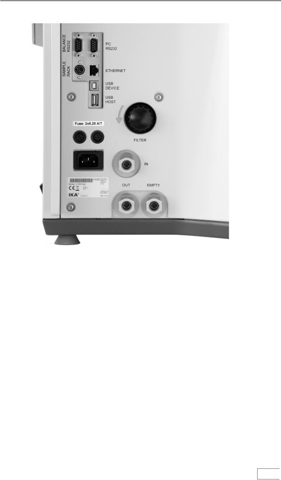
Interfaces
Water filter
Mains power supply
Water |
Oxygen |
10
Description of system components
Hoses
•Discharge hose
(empty) |
C 6000 |
• |
Infl ow pipe |
|
|
|
|
|
(in) |
Condenser |
C 6000 |
|
|
|
||
• |
Return pipe |
|
|
|
|
|
(out) |
|
|
|
|
|
|
|
• |
Venting hose |
|
|
|
|
|
(out) |
|
C 6000 |
|
|
|
|
|
• |
O2 connection tube |
M8x1 |
C 6000 |
|
|
|
(in) |
|
|
|
|
|
|
|
Commissioning
Place of installation
A constant ambient temperature is an important |
For operation of the system the following must be |
||
requirement for ensuring the high measuring |
available at the place of installation: |
||
accuracy of the system. The following conditions |
- A power supply corresponding to the nameplates |
||
must therefore be fulfilled at the place of |
|
on the system components, |
|
installation: |
- An oxygen supply (99.95 % pure oxygen, quality |
||
• No direct solar radiation |
|
3.5; pressure 30 bar) with pressure gauge. |
|
A shut-off valve for the oxygen supply must be |
|||
|
|||
• No draughts (e.g. beside windows, doors, air |
installed. Observe the instructions on handling |
||
conditioning) |
oxygen given in the chapter „Safety instructions“. |
||
|
Please read these operating instructions carefully. |
||
• Su cient distance to radiators and other heat |
IKA® consider themselves responsible for the |
||
sources |
safety, reliability and performance of the appliance |
||
|
only when |
||
• The minimum distance between the wall and |
• |
the device has been operated in accordance |
|
the rear side of the device must be at least 25 |
|||
cm. |
|
with the operating instructions, |
|
• The system must not have laboratory hardware |
• |
the specifi cations for the place of |
|
such as shelves, wire ducts, ring lines, etc. |
|
installation have been met. |
|
installed above it. |
Do not use distilled or demineralized water |
||
|
|||
• The (constant) room temperature should be |
(increased risk of corrosion)! Fill the cooler |
||
around 20 °C ... 25 °C. |
according to the cooler operating instructions. is |
||
|
recommended in drinking tap water quality. Mix |
||
• The system must be set up on a horizontal |
in (max. 1 ml for 4-5 l of water) of the supplied |
||
surface. |
water additive. Thus, the durability of the water is |
||
|
improved. |
||
11
Description of system components

Connection to the condenser
Rear view without hoses attached
Make sure the filter casing is always securely closed (see „Servicing and cleaning the filter“)!
Insert the inflow pipe into the „IN“ port until it clicks home. Connect the other end of the pipe to the „OUT“ port of the condenser (water pressure max 1.5 bar).
Insert the return pipe into the „OUT“ port until it clicks home. Connect the other end of the pipe to the „IN“ port of the condenser.
The connection „EMPTY“ is intended only for emptying the device, e.g. for transport purposes. In normal operation the discharge hose need not be inserted!
Connection to the water
Operatrion is only allowed with the pressure valve IKA® C 25!
The IKA® C 25 pressure valve is absolutely essential on the water faucet for operation of the calorimeter,
and it must be preset to an output pressure of approximately 1.5 bar. The valve is installed into the line of the water connection, see operating instruction IKA® C 25.
12
Commissioning

Connecting the oxygen supply
Insert the O2 connection tube into the calorimeter „IN“ port until it clicks home and connect the free end to the pressure reducer, using the adapters supplied if necessary. IKA® C 29. Removal entails the same operations performed in the reverse sequence.
Note: The O2 connection tube can be removed only after it has been depressurised.
Screw the venting hose to the screw coupling (8 AF) on the calorimeter and position the free end under the extractor hood or connect it to a gas washing device. Comply with the applicable safety regulations in this respect.
O2 connection tube IN max. 4 MPa
Venting hose
IKA® C 29
The venting hose discharges the combustion gases from the decomposition vessel after every combustion trial. When laying the venting hose ensure that it is not crushed or kinked.
Connection to the mains power supply
DANGER Combustion gases are hazardous to health,
therefore the venting hose must be connected to a suitable gas cleaning system or extraction system.
Check that the available mains power supply matches the mains power supply particulars listed on the rating plate.
13
Commissioning
Connection of peripherals
Note: While the peripheral devices are being connected, they and the calorimeter must be turned-off on the mains power switch!
RS232 PC: |
Serial connection for controlling the calorimeter using CALWIN or operating |
||||
|
with serial printer C1.50. |
|
|
|
|
|
Standard setting : |
Baud rate: |
9600 |
|
|
|
|
Data bits: |
8 |
|
|
|
|
Stop bits: |
1 |
|
|
|
|
Parity: |
none |
||
|
|
Handshake: |
none |
||
RS232 BALANCE: |
Interface for connecting scales (Mettler, Ohaus, Sartorius, Kern) |
||||
|
Standard setting : |
Baud rate: |
1200 |
|
|
|
|
Data bits: |
7 |
|
|
|
|
Parity: |
odd |
||
|
|
Stop bits: |
1 |
|
|
|
|
Handshake: |
none |
||
ETHERNET: |
Network connection for data transfer via the network, e.g. to a network printer. |
||||
USB-DEVICE: |
USB interface (only for service). |
|
|
|
|
USB-HOST: |
Interface for connection of a printer or with a USB mouse. |
||||
SAMPLE-RACK: |
Interface for connection of the C 5020 sample rack. |
|
|
|
|
|
|
|
|
|
|
|
|
|
14 |
||
Commissioning
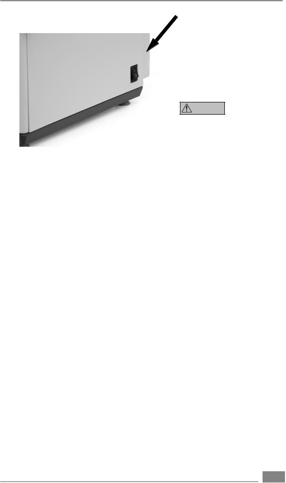
On/off switch
The device is switched on and off via the on/off switch located on the righthand side.
Switch the device off at the on/off switch.
Lift moves upwards.
Switch the appliance off only by using the menu commands.
Lift moves downwards.
ATTENTION Data may be lost if the appliance is switched off
other than by following the menu commands.
Note: Switch the device off at the on/off switch only when directed to do so by the menu command.
15
Commissioning

Display and operating elements
After the IKA® C 6000 global standards/ isoperibol calorimeter has been switched on, the touch screen display is active and can be operated using the stylus or finger.
Explanation of the screen display
Schematic representation of he display components
A C
G
I H
Pos. Designation
A Tab
CArrow symbol, tabs
DArrow symbol, vertical scroll bar
EVertical scroll bar
FInfo line
GArrow symbol, horizontal scroll bar
HHorizontal scroll bar
IControl button
D
E
D
F
G
Other view-based presentations of display components are described in the relevant section.
16
Display and operating elements

The contents of the screen display are often distributed over several tabs. You can switch between tabs at any time by clicking on them. Thus for instance the screen display during the
List display calorimetric standard procedure consists of the three views „Measurements“, „Device“ and
„Graphics“.
Status symbols
Green tick
Measurement completed but not yet evaluated, or selection acknowledgement.
Pocket calculator
Measurement completed end evaluated, evaluation inputs can no longer be changed.
Blank tick
Measurement prepared but not yet performed.
Yellow X
Field property not selected, or cancelled before ignition.
Red X
Cancellation after ignition.
Circle
Measurement selected.
List displays and report fields have scroll bars. Clicking on the pale areas of the scroll bar scrolls the list display or report field. Clicking in the dark area and dragging it allows you to move continuously through the display, as does clicking on the arrow symbols and maintaining the selection.
Report field
Note: Greyed-out fields cannot be selected.
17
Display and operating elements
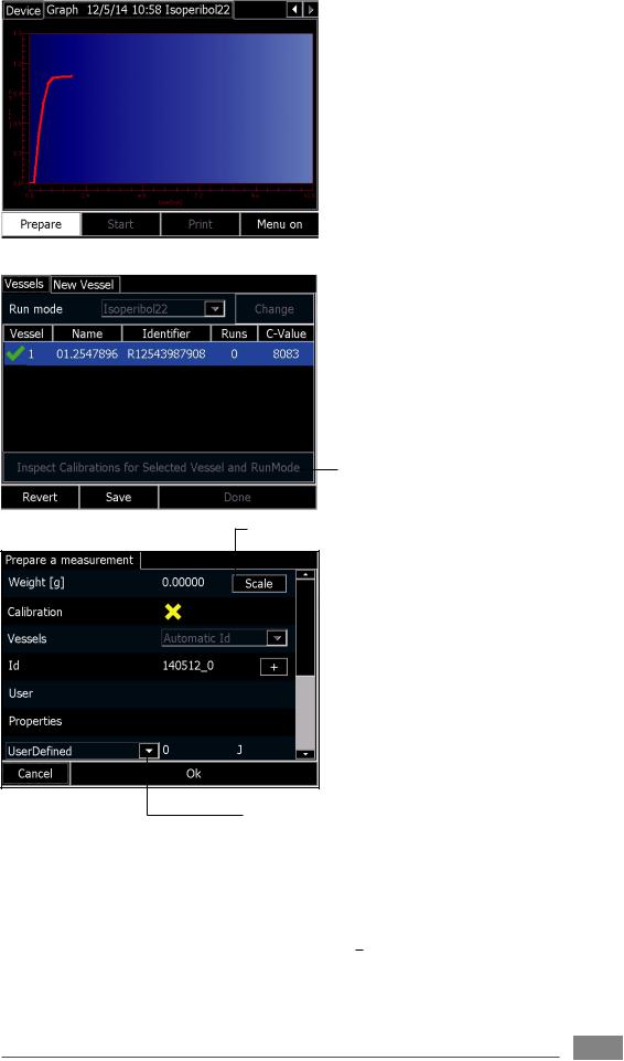
The view „Graph“ shows the temperature by time.
Switch
Selection
box
The most important actions available at any point in time are gathered together as clickable buttons along the bottom edge of the screen.
Switch
To initiate an action it is su cient to click on one of the discrete areas showing the relevant images or text. For instance during the „Preparation for measurement“ dialogue the most important actions are explained below.
Weighted sample
Permits manual input of a weight value using the virtual keyboard.
Calibration
Selection field for marking a calibration (on/off).
Decomposition vessel
Manual selection box when decomposition vessel detection is inactive.
Name
Alphanumeric editable field
User
Alphanumeric editable field
Properties
Alphanumeric editable field
IKA® thread
Selection box which allows a selection list to be opened.
18
Display and operating elements

Weighted sample
Input of a numerical value, such as weighted sample:
The entire area with the exception of the „Balance“ button is available to be clicked here. A numerical virtual keyboard is opened and can be used to input the value:
After the virtual keyboard has been closed with „OK“, the value in the input field is loaded. Alternatively, clicking on the „Balance“ button automatically loads a value from a connected balance.
Selection box
Shift key for upper and lower case letters and special characters
Input of an alphanumeric value, such as „Designation“ :
Here again the entire area is available to be clicked. A complete virtual keyboard is opened.
Note: The maximum input is 23 characters.
After the virtual keyboard has been closed with „OK“, the value in the input field is loaded.
Select from a selection box, e.g. for the ignition aid:
After the selection box has been clicked, a list of the options is displayed. The option that is clicked is selected.
Single selection field, such as calibration :
Clicking on the entire area allows the prepared measurement to be marked as a calibration.
19
Display and operating elements

Working with the IKA® C 6000 global standards/isoperibol calorimeter
Switching on the device
The IKA® C 6000 global standards/isoperibol is switched on with the On/off switch. The cover opens automatically. A start screen appears for about 30 seconds, during which the hardware is initialised and the software is loaded.
System test
The system test is performed automatically every time the IKA® C 6000 global standards/isoperibol is
switched on.
During the system test the start screen is shown again; clicking on the „Show details“ button provides detailed information.
Safety instructions regarding information on and activation of the calorimeter are then shown on
the IKA® Homepage.
The system test includes the following steps:
- Testing the external water circuit with the circulation pump and heater (approx. 30 to 45 seconds).
- Testing the internal water circuit with the condenser and water supply, plus the heater once again (approx. 30 to 45 seconds).
- Testing whether the temperature of the cooling waters is correct for the selected function of the IKA® C 6000 global standards/isoperibol. (approx. 60 to 180 seconds).
If any one of these steps is not performed successfully, the system test stops with an error message. After all the components have been checked the system test can be restarted the same as after a manual cancellation. To do this, press the „Restart“ button.
With the system test in standby, no measurements can be made. However it is possible to se-
lect some menu options. |
|
|
20 |
Working with the IKA® C 6000 global standards/isoperibol calorimeter
 Loading...