


50 055 00 c
RCT basic safety control
HCT basic safety control
Betriebsanleitung |
DE |
4 |
Ursprungssprache |
|
|
Operating instructions |
EN |
14 |
Mode d’emploi |
FR |
24 |
Indicationes de seguridad |
ES |
34 |
Veiligheidsinstructies |
NL |
36 |
Norme di sicurezza |
IT |
38 |
Säkerhetsanvisningar |
SV |
40 |
Sikkerhedshenvisninger |
DA |
42 |
Sikkerhetsanvisninger |
NO |
44 |
Turvallisuusohjeet |
FI |
46 |
Instruções de serviço |
PT |
48 |
Wskazówki bezpieczeństwa |
PL |
50 |
Bezpečnostní pokyny |
CS |
52 |
Biztonsági utasitások |
HU |
54 |
Varnostna opozorila |
SL |
56 |
Bezpečnostné pokyny |
SK |
58 |
Ohutusjuhised |
ET |
60 |
Drošības norādes |
LV |
62 |
Nurodymai dėl saugumo |
LT |
64 |
R_HCT_082011 |
Reg.-No. 4343-01 |

CE-Konformitätserklärung
Wir erklären in alleiniger Verantwortung, dass dieses Produkt den Bestimmungen der Richtlinien 2006/95/EG und 2004/108/ EG entspricht und mit den folgenden Normen und normativen Dokumenten übereinstimmt: DIN EN IEC 61010-1, -2-010 und DIN EN IEC 61326-1.
CE-Declaration of conformty
We declare under our sole responsibility that this product is in compliance with the regulations 2006/95/EC and 2004/108/EC and conforms to the standards or standardized documents DIN EN IEC 61010-1, -2-010 and DIN EN IEC 61326-1.
Déclaration de conformité CE
Nous déclarons sous notre propre responsabilité que ce produit est conforme aux réglementations 2006/95/EG et 2004/108/EG et en conformité avec les normes ou documents normalisés suivant DIN EN IEC 61010-1, -2-010 et DIN EN IEC 61326-1.
R_HCT_042011 |
2 |
|

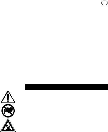
RCT basic safety control
A B L K
M
 F
F

 D
D
J C
G H I E
Fig. 1
HCT basic safety control
A B L K
M
C

 J
J
G H I E
Fig. 2
Pos. |
Bezeichnung |
Item |
Designation |
Pos. Désignation |
|
A |
Geräteschalter |
A |
Main Switch |
A |
Commutateur |
B |
einstellbarer Sicherheitskreis |
B |
Adjustable safety circuit |
B |
Circuit de sécurité réglable |
C |
Bedienknopf Heizung |
C |
Rotary knob, heater |
C |
Bouton rotatif de chauffage |
D |
Bedienknopf Motor |
D |
Rotary knob, motor |
D |
Bouton rotatif du moteur |
E |
LED-Display Heizung |
E |
LED display, heater |
E |
Affichage DEL chauffage |
F |
LED-Display Motor |
F |
LED display, motor |
F |
Affichage DEL moteur |
G |
LED Heizplatte |
G |
LED, heating plate |
G |
DEL plaque chauffante |
H |
LED externer Temperatursensor |
H |
LED, external temperature sensor |
H |
DEL capteur de température externe |
I |
LED (Set=Sollwert) |
I |
LED (set=set point value) |
I |
DEL (set=valeur théorique) |
J |
LED externer Temperatursensor |
J |
LED, external temperature sensor |
J |
DEL capteur de température externe |
K |
Netzbuchse |
K |
Power socket |
K |
Prise secteur |
L |
Kontaktthermometerbuchse |
L |
Socket, contact thermometer |
L |
Prise du thermocontact |
M |
Stativgewindebohrung |
M |
Threaded hole for stand |
M |
Alésage fileté du statif |
R_HCT_042011 |
3 |
|

Inhaltsverzeichnis |
DE |
|
|
Seite |
|
|
|
|
CE - Konformitätserklärung |
2 |
|
Sicherheitshinweise |
4 |
|
Auspacken |
6 |
|
Bestimmungsgemäßer Gebrauch |
6 |
|
Montage Stativstab |
6 |
|
Bedienung |
7 |
|
Betriebsmodi einstellen |
8 |
|
Sicherheitstemperaturgrenze einstellen |
8 |
|
Regelung der Mediumstemperatur mit ETS-D |
9 |
|
oder Kontaktthermometer |
|
|
Temperatur-Regelmodus einstellen |
10 |
|
Instandhaltung |
10 |
|
Zubehör |
10 |
|
Fehlercodes |
11 |
|
Technische Daten |
12 |
|
Gewährleistung |
13 |
|
Sicherheitshinweise
Zu Ihrem Schutz
•Lesen Sie die Betriebsanleitung vor Inbetriebnahme vollständig und beachten Sie die Sicherheitshinweise.
•Bewahren Sie die Betriebsanleitung für Alle zugänglich auf.
•Beachten Sie, dass nur geschultes Personal mit dem Gerät arbeitet.
•Beachten Sie die Sicherheitshinweise, Richtlinien, Arbeitsschutzund Unfallverhütungsvorschriften.
•Steckdose muss geerdet sein (Schutzleiterkontakt).
Stellen Sie vor Inbetriebnahme sicher, dass das Anschlusskabel des Gerätes zur Steckdose passt und eine sichere Schutzleiter-
verbindung gewährleistet ist.
•Achtung - Magnetismus! Beachten Sie die Auswirkungen des Magnetfeldes (Herzschrittmacher, Datenträger...).
•Verbrennungsgefahr! Vorsicht beim Berühren von Gehäuseteilen und Heizplatte. Die Heizplatte kann über 310 °C heiß werden. Beachten Sie die Restwärme nach dem Ausschalten!
•Das Netzkabel darf die heizbare Aufstellplatte nicht berühren.
•Tragen Sie Ihre persönliche Schutzausrüstung entsprechend der Gefahrenklasse des zu bearbeitenden Mediums. Ansonsten besteht eine Gefährdung durch:
-Spritzen und Verdampfen von Flüssigkeiten
-Herausschleudern von Teilen
-Freiwerden von toxischen oder brennbaren Gasen.
•Stellen Sie das Gerät frei auf einer ebenen, stabilen, sauberen, rutschfesten, trockenen und feuerfesten Fläche auf.
•Die Gerätefüße müssen sauber und unbeschädigt sein.
•Prüfen Sie vor jeder Verwendung Gerät und Zubehör auf
Beschädigungen. Verwenden Sie keine beschädigten Teile.
•Reduzieren Sie die Drehzahl, falls
-Medium infolge zu hoher Drehzahl aus dem Gefäß spritzt
-unruhiger Lauf auftritt
-das Gefäß sich auf der Aufstellplatte bewegt.
•Achtung! Mit diesem Gerät dürfen nur Medien bearbeitet bzw. erhitzt werden, deren Flammpunkt über der eingestellten Sicherheitstemperaturbegrenzung liegt (50 ... 360 °C).
Die eingestellte Sicherheitstemperaturbegrenzung muss immmer mindestens 25 °C unterhalb des Brennpunktes des verwendeten Mediums liegen.
•Beachten Sie eine Gefährdung durch
-entzündliche Materialien
-brennbare Medien mit niedriger Siedetemperatur
-Glasbruch
-falsche Dimensionierung des Gefäßes
-zu hohen Füllstand des Mediums
-unsicherer Stand des Gefäßes.
R_HCT_042011 |
4 |
|

•Im Betrieb kann sich das Gerät erwärmen.
•Die Aufstellpatte kann sich auch ohne Heizbetrieb durch den
Antriebsmagneten bei hohen Drehzahlen erwärmen.
•Verarbeiten Sie krankheitserregende Materialien nur in geschlossenen Gefäßen unter einem geeigneten Abzug. Bei Fragen wenden Sie sich bitte an IKA.
•Betreiben Sie das Gerät nicht in explosionsgefährdeten Atmosphären, mit Gefahrstoffen und unter Wasser.
•Bearbeiten Sie nur Medien, bei denen der Energieeintrag durch das Bearbeiten unbedenklich ist. Dies gilt auch für andere Energieeinträge, z.B. durch Lichteinstrahlung.
•Beachten Sie die Betriebsanleitung des Zubehöres.
•Tauchen Sie externe Temperaturmessfühler (PT 1000, ETS-D...) mindestens 20 mm tief in das Medium ein.
•Der angeschlossene externe Temperaturmessfühler PT 1000 muss sich immer im Medium befinden.
•Sicheres Arbeiten ist nur mit Zubehör, das im Kapitel „Zubehör“ beschrieben wird, gewährleistet.
•Zubehörteile müssen sicher mit dem Gerät verbunden sein und dürfen sich nicht von alleine lösen. Der Schwerpunkt des Auf baus muss innerhalb der Aufstellfläche liegen.
•Montieren Sie Zubehör nur bei gezogenem Netzstecker.
•Die Trennung des Gerätes vom Stromversorgungsnetz erfolgt nur durch Ziehen des Netzbzw. Gerätesteckers.
•Die Steckdose für die Netzanschlussleitung muss leicht erreichbar und zugänglich sein.
•Nach einer Unterbrechung der Stromzufuhr läuft das Gerät im
Modus B von selbst wieder an.
•Eventuell kann Abrieb von rotierenden Zubehörteilen in das zu bearbeitende Medium gelangen.
•Bei Verwendung von PTFE-ummantelten Magnetstäbchen ist
Folgendes zu beachten: Chemische Reaktionen von PTFE treten ein im Kontakt mit geschmolzenen oder gelösten Alkaliund Erdalkalimetallen, sowie mit feinteiligen Pulvern von Metallen aus der 2. und 3. Gruppe des Periodensystems bei Temperatu-
ren über 300-400 °C. Nur elementares Fluor, Chlortrifluorid und Alkalimetalle greifen es an, Halogenkohlenwasserstoffe wirken reversibel quellend.
(Quelle: Römpps Chemie-Lexikon und „Ullmann“ Bd.19)
Zum Schutz des Gerätes
•Das Gerät darf nur von einer Fachkraft geöffnet werden.
•Spannungsangabe des Typenschildes muss mit Netzspannung
übereinstimmen.
•Decken Sie das Gerät nicht ab, auch nicht teilweise, z.B. mit metallischen Platten oder Folien. Die Folge ist Überhitzung.
•Vermeiden Sie Stöße und Schläge auf Gerät oder Zubehör.
•Achten Sie auf eine saubere Aufstellplatte.
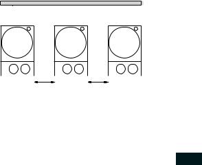
•Beachten Sie die Mindestabstände zwischen Geräten, zwischen
Gerät und Wand, sowie oberhalb des Aufbaus (min. 800 mm), siehe Fig. 3.
>100 mm
>100 mm |
>100 mm |
Fig. 3 |
R_HCT_042011 |
5 |
|

Auspacken
•Auspacken
-Packen Sie das Gerät vorsichtig aus
-Nehmen Sie bei Beschädigungen sofort den Tatbestand auf (Post, Bahn oder Spedition)
•Lieferumfang
RCT basic safety control |
HCT basic safety control |
- Beheizbarer Magnetrührer |
- Heizgerät |
- Netzkabel |
- Netzkabel |
- Betriebsanleitung |
- Betriebsanleitung |
- Schraubendreher |
- Schraubendreher |
- Schutzhaube |
- Schutzhaube |
- Temperaturfühler PT 1000 |
- Temperaturfühler PT 1000 |
nicht bestimmungsgemäßem Gebrauch entgegen der Herstellervorgabe betrieben wird oder wenn Veränderungen an Gerät oder Leiterplatte durch Dritte vorgenommen werden.
Montage Stativstab
FSchraubstopfen (M) entfernen
FSchutzkappe von Stativstab abziehen
FUnterlegscheibe zwischen Gehäuse und Mutter legen
FStativstab von Hand bis zum Anschlag einschrauben
FMutter mit einem Gabelschlüssel SW17 anziehen
FZubehör mit Kreuzmuffen montieren
Bestimmungsgemäßer Gebrauch
•Verwendung
- zum Mischen und / oder Erhitzen von Flüssigkeiten
•Verwendungsgebiet
- |
Laboratorien |
- Schulen |
- |
Apotheken |
- Universitäten |
Das Gerät ist für den Gebrauch in allen Bereichen geeignet, außer Industriebereichen.
Der Schutz für den Benutzer ist nicht mehr gewährleistet, wenn das Gerät mit Zubehör betrieben wird, welches nicht vom Hersteller geliefert oder empfohlen wird oder wenn das Gerät in
Hinweis: Zum Arbeiten mit Badaufsätzen |
|
über ø 180 mm verwenden Sie bitte den |
|
Stativstab H 16 V zusammen mit dem |
|
Ausleger H 16.1. |
Fig. 6 |
|
R_HCT_042011 |
6 |
|

Vor Inbetriebnahme Schutzfolie von der Aufstellplatte entfernen!
Bedienung
|
|
RCT basic safety control |
|
|
|
HCT basic safety control |
|||
|
|
|
|||||||
|
|
|
|
|
|
|
|
|
|
Inbetrieb- |
|
F Geräteschalter (A) in OFF-Stellung bringen |
|||||||
|
F Netzkabel in Netzbuchse (K) einstecken |
||||||||
nahme |
|
F Geräteschalter (A) in ONStellung bringen |
|||||||
|
|
|
a Standard Modus A ist eingestellt (siehe “Betriebsmodi”) |
||||||
|
|
F Motordrehzahl mit dem Bedienknopf (D) einstellen |
|
|
|
|
|
||
|
|
|
|
|
|
|
|||
Rühren |
a Der eingestellte Wert wird auf dem Display (F) angezeigt |
|
|
|
|||||
F Start der Rührfunktion durch Drücken des Bedienknopf (D) |
|
|
|
||||||
|
|
|
|
|
|||||
|
i a Angezeigter Wert blinkt bis zum Erreichen der eingestellten Drehzahl |
|
|
|
|||||
|
|
|
|
|
|
|
|
|
|
|
|
F Einstellen der Sicherheitstemperaturgrenze, (siehe “Sicherheitstemperaturgrenze einstellen bei RCT und HCT”) |
|||||||
|
|
F Solltemperatur mit dem Bedienknopf (C) einstellen |
|||||||
|
|
a Der eingestellte Wert wird auf dem Display (E) angezeigt |
|||||||
|
|
F Einstellen des Temperatur-Regelmodus (siehe “Temperatur-Regelmodus einstellen bei RCT und HCT”) |
|||||||
|
|
F Start der Heizfunktion durch Drücken des Bedienknopfes (C), auch bei Verwendung eines Kontaktthermometers |
|||||||
Heizen |
|
Sollund IstTemperatur wird im Wechsel auf dem Display (E) angezeigt: |
|||||||
|
i |
a Bei eingeschalteter Heizung leuchtet die LED (G), Solltemperaturanzeige LED (I) leuchtet |
|||||||
|
|
|
Die einstellbare Heizplattentemperatur beträgt max. 310°C |
|
|
||||
|
|
|
|
|
|||||
|
i |
a Solange die Temperatur der Aufstellfläche 50 °C überschreitet wird im Rührund Standby- |
|||||||
|
|
Betrieb auf dem Display (E) |
HOt |
angezeigt |
|||||
FGeräteschalter (A) in OFF-Stellung bringen
FKontaktstecker (L) abziehen
FSicherheitskontaktthermometer nach DIN 12878 Klasse 2 oder
|
Anschluss |
|
Temperaturfühler PT 1000 mit Buchse (L) verbinden |
|||
|
|
F Geräteschalter (A) in ON-Stellung bringen |
||||
|
externer |
|
||||
|
i |
Temperaturfühler PT 1000 |
a Die auf dem Display (E) angezeigte Ist-Temperatur des Tem- |
|||
|
Thermometer |
|||||
|
(direkte Temperatur- |
|
|
peraturfühlers entspricht der Mediumstemperatur. |
||
|
regelung im Medium) |
|
|
LED “externer Temperatursensor” (H) leuchtet. |
||
|
|
i |
Kontaktthermometer z.B. ETS-D5 |
a Bedienungsanweisung des Kontaktthermometers beachten |
||
|
|
|
|
LED (J) “Dezimalpunkt der Temperaturanzeige” leuchtet |
||
|
|
|
|
a Auf dem Display (E) wird bei angeschlossenem Kontaktther- |
||
|
|
|
|
mometer nur noch die eingestellte SollTemperatur angezeigt |
|
|
|
R_HCT_042011 |
|
|
|
7 |
|
|
|
|
|
|
||

Betriebsmodi einstellen
RCT basic safety control
Gerätebetrieb mit Modus A oder B
Modus A
Alle eingestellten Werte bleiben nach dem Ausschalten oder dem Trennen des Gerätes vom Netz erhalten. Nach dem Einschalten des Gerätes ist der Status der Funktionen Rühren und Heizen ausgeschaltet (OFF).
Modus B
Alle eingestellten Werte bleiben nach dem Ausschalten oder dem Trennen des Gerätes vom Netz erhalten. Nach dem Einschalten des Gerätes wird der Status der Funktionen Heizen und Rühren vor dem letzten Ausschalten übernommen (ON oder OFF).
Werkseinstellung: Modus A |
|
|
|
|
Der eingestellte Modus wird beim Start des |
|
|
|
|
xx |
A |
|
||
Gerätes auf dem Display angezeigt |
|
|
||
Modus ändern |
(xx: Softwareversion) |
Modus |
||
FGeräteschalter (A) in OFF-Stellung bringen
FBedienknöpfe (C und D) gedrückt halten
FGeräteschalter (A) in ONStellung bringen
FBedienknöpfe (C und D) loslassen
ia Anzeige des eingestellten Wertes auf dem Display xx A
HCT basic safety control
Gerätebetrieb mit voreingestelltem Modus
Der Betriebsmodus ist fest eingestellt und nicht zu ändern.
Beschreibung Modus und Darstellung Display siehe RCT.
Werkseinstellung: Modus A
R_HCT_042011
Sicherheitstemperaturgrenze einstellen
Nach dem Einschalten des Gerätes wird die
eingestellte Sicherheitstemperaturgrenze 360 SAFE angezeigt.
Werkseinstellung: ca. 360 °C
Einstellbereich: > 50 - 360 °C
Sicherheitstemperaturgrenze einstellen
FGeräteschalter (A) in OFF-Stellung bringen
FEinstellen der Sicherheitstemperatur mit Schraubendreher i a Anzeige des eingestellten Wertes auf dem
Display
Die einstellbare Heizplattentemperatur
von max. 310 °C liegt mindestens Fig. 5 10 °C unter der eingestellten
Sicherheitstemperaturgrenze.
Achtung: Die eingestellte Sicherheitstemperaturgrenze muss immer mindestens 25 °C unterhalb des Brennpunktes des zu bearbeitenden Mediums liegen!
Funktionstest Sicherheitsskreisabschaltung
FSicherheitstemperaturgrenze auf Linksanschlag stellen (50°C)
FGeräteschalter (A) in ON-Stellung bringen
i |
a Anzeige auf dem Display |
Err 25 |
8

R_HCT_042011
Regelung der Mediumstemperatur mit ETS-D oder Kontaktthermometer
Die Regelung der Mediumstemperatur mit ETS-D oder Kontaktthermometer ist zu bevorzugen. Man erhält damit nach Einstellung der Solltemperatur eine kurze Aufheizzeit, praktisch keine Temperaturdrift und eine geringe Temperaturwelligkeit.
Zusätzlich zur präzisen Regelfunktion, ist der ETS-D durch die an ihm einstellbare “MAXTEMP” ein direkt auf die Mediumstemperatur bezogener Temperaturbegrenzer. Bei Überschreitung dieser “MAXTEMP”, z.B. durch einen Defekt im Regelkreis oder durch unbeabsichtigtes
Verstellen der “Safe Temp” oder Solltemperatur am
RCT oder HCT, schaltet der ETS-D direkt den getrennten Sicherheitskreis des RCT oder HCT bleibend aus.
Die Rührfunktion läuft dann mit der vor der Störung eingestellten Drehzahl weiter. An der Rückseite des Gerätes befindet sich eine 6polige Buchse zum Anschluß des ETS-D, des Kontaktthermometers oder des Kontaktsteckers. Die Elektronik des Gerätes liefert einen Prüfstrom der über die Steckerstifte 3 und 5 der Buchse fließen muss, damit die Heizplatte heizt.
Sicherheitskontaktthermometer
nach DIN 12 878 Klasse 2 oder nach Gerstel werden mit einem 3-ad- rigen Kabel angeschlossen, der Prüfstrom fließt durch das Kontaktthermometer.
Sicherheitsfunktion:
Wird der Prüfstrom z.B. durch Bruch des Kontaktthermometers oder Herausfallen des Kabelsteckers unterbrochen, schaltet die Heizung ab. Über der Diodenbuchse ist auf einem Hinweisschild die erforderliche Steckerbelegung angegeben.
Kontaktthermometer ohne Sicherheitskreis
nach DIN 12 878 Klasse 0. Das Gerät heizt nur, wenn der Prüfstromkreis durch eine elektrische Verbindung der Steckerstifte 3 und 5 geschlossen ist.
2-adrige Anschlußkabel:
Steckerstifte 3 und 5 des geräteseitigen Steckers miteinander verbinden.
3-adrige Anschlußkabel:
Hier kann der Prüfstromkreis auch im Anschlußkopf des Kontaktthermometers hergestellt werden (Steckerstift 2 und 3 miteinander verbinden). - Sicherheitsvorteil!
Ein 3-adriges Kabel mit der erforderlichen Brücke ist lieferbar. (Zubehör)
Einstellungen
Die detaillierten Einstellanweisungen und Grenzwerte entnehmen Sie der Betriebsanleitung des anzuschließenden Gerätes.
Am ETS-D oder Kontaktthermometer wird die gewünschte Mediumstemperatur eingestellt. Zusätzlich kann beim
ETS-D noch eine “MAXTEMP”, d. h. in Verbindung mit dem RCT oder HCT, eine maximale Mediumstemperatur bei Störungen eingestellt werden. Am Drehknopf “Temp” des Gerätes wird die erforderliche Oberflächentemperatur der Heizplatte vorgewählt.
Stellt man den Drehknopf “Temp” auf die maximal einstellbare
Temperatur, ergibt sich das schnellstmögliche Aufheizen, die Mediumstemperatur kann jedoch über die am z.B. Kontaktthermometer eingestellte Solltemperatur schwingen. Stellt man den
Drehknopf “Temp” ungefähr auf den doppelten Sollwert (bei einem Sollwert von 60 °C wird der Temp-Drehknopf auf 120 °C gestellt), ergibt sich ein guter Kompromiß zwischen schnellem Aufheizen und Überschwingen.
Stellt man den Temp-Drehknopf exakt auf die Solltemperatur, erreicht das Medium die Solltemperatur nicht, da immer etwas Wärmegefälle zwischen Heizplatte und Medium auftritt.
An der “SafeTemp” Einstellachse wird die maximale Heizplattentemperatur bei Störungen des Regelkreises eingestellt.
9

R_HCT_042011
TemperaturRegelmodus einstellen
Der Anwender kann beim Regeln mit einem externen PT1000Temperaturfühler zwischen zwei Arten der Regelung wählen:
PI-Modus
Gute Regelergebnisse, minimiertes Überschwingen, langsamer
2P-Modus (Zweipunktregler)
Maximale Aufheizgeschwindigkeit, größeres Überschwingen
Werkseinstellung: PI-Modus
TemperaturRegelmodus ändern
1.Solltemperatur auf 2 °C einstellen
2.Gerät ausschalten
3.Temp-Drehknopf gedrückt halten
4.Gerät einschalten
Dadurch wird der Zweipunkt-Regler (2P) für den externen PT1000-Tem- peraturfühler aktiviert (2P erscheint auf der Anzeige) bzw. deaktiviert.
Beim Einschalten des Gerätes wird bei aktiviertem ZweipunktRegler neben der Betriebsart A/B auch 2P angezeigt.
Bei aktiver Heizfunktion im 2P-Mode (mit externem PT1000-Tem- peraturfühler) blinkt die Ist-Temperatur - das ist ein Hinweis für den
Anwender, dass die Mediumstemperatur stärker überschwingt!
Kosmetika |
Tensidhaltiges Wasser, Isopropanol |
Nahrungsmitteln |
Tensidhaltiges Wasser |
Brennstoffen |
Tensidhaltiges Wasser |
Beim Reinigen darf keine Feuchtigkeit in das Gerät dringen.
-Tragen Sie zum Reinigen des Gerätes Schutzhandschuhe.
-Falls andere als die empfohlenen Reinigungsoder Dekontaminationsmethoden angewendet werden, fragen Sie bitte bei IKA nach.
Ersatzteilbestellung
Bei Ersatzteilbestellungen geben Sie bitte Folgendes an:
-Gerätetyp
-Fabrikationsnummer des Gerätes, siehe Typenschild
-Positionsnummer und Bezeichnung des Ersatzteiles, siehe www.ika.com.
Reparaturfall
Im Reparaturfall muss das Gerät gereinigt und frei von gesundheitsgefährdenden Stoffen sein.
Senden Sie das Gerät in der Originalverpackung zurück. Lagerverpackungen sind für den Rückversand nicht ausreichend. Verwenden Sie zusätzlich eine geeignete Transportverpackung.
Instandhaltung
Das Gerät arbeitet wartungsfrei. Reinigung


 Ziehen Sie zum Reinigen den Netzstecker. Verwenden Sie nur von IKA empfohlene Reinigungsmittel. Verwenden Sie zum Reinigen von:
Farbstoffen |
Isopropanol |
Baustoffen |
Tensidhaltiges Wasser, Isopropanol |
Zubehör
•Rührstäbe: ø 6 mm, Länge bis 15 mm
ø7 mm, Länge bis 60 mm
ø10mm, Länge bis 80 mm
•RS1 |
Rührstäbchenset |
•ETS-D5 |
Kontaktthermometer |
•RSE |
Rührstäbchenentferner |
•ETS-D6 |
Kontaktthermometer |
•H15 |
Badaufsatz |
•H28 |
Badaufsatz |
•H29 |
Ölbadaufsatz |
•H30 |
Ölbadaufsatz |
•H16V |
Stativstab |
•H16.1 |
Ausleger |
•H38 |
Haltestange |
•H44 |
Kreuzmuffe |
10
Fehlercodes
Eine Störung während des Betriebes wird durch eine Fehlermeldung im Display (E und F) angezeigt.
Gehen Sie dann wie folgt vor:
FGerät am Geräteschalter (A) ausschalten
FKorrekturmaßnahmen treffen
FGerät erneut starten
Fehlercode |
|
Ursache |
|
Folge |
|
Korrektur |
|
|
|
||||
E3 |
|
Geräteinnentemperatur zu hoch |
|
Heizung aus |
|
- Gerät ausschalten und abkühlen lassen |
|
|
|
|
|
|
|
E4 |
|
Motor blockiert |
|
Heizung aus |
|
- Gerät ausschalten |
|
|
|
|
Motor aus |
|
- Achtung! Nur für autorisiertes Servicepersonal: |
|
|
|
|
|
|
Steckverbindung des Motors im Geräteinneren überprüfen |
|
|
|
|
|
|
|
E6 |
|
Unterbrechung im Sicherheitskreis |
|
Heizung aus |
|
- Kontaktstecker (L) stecken |
|
|
|
|
|
|
- Kontaktthermometer PT 1000/ Temperaturfühler stecken |
|
|
|
|
|
|
- Defekte Verbindungskabel, Stecker oder Kontaktthermome- |
|
|
|
|
|
|
ter austauschen |
E24 |
|
Oberflächentemperatur (Temperatur des Regelfühlers): |
|
Heizung aus |
|
- Gerät ausschalten, bis die Oberflächentemperatur der Auf- |
|
|
der Aufstellplatte ist höher als die eingestellte Sicher- |
|
|
|
stellplatte niedriger ist als die eingestellte Sicherheitstempe-- |
|
|
heitstemperaturgrenze |
|
|
|
raturgrenze |
|
|
|
|
|
|
- Sicherheitstemperaturgrenze höher einstellen |
E44 |
|
Oberflächentemperatur (Temperatur des Sicherheitsfühlers): |
|
Heizung aus |
|
- Gerät ausschalten, bis die Oberflächentemperatur der Auf- |
|
|
der Aufstellplatte ist höher als die eingestellte Sicher- |
|
|
|
stellplatte niedriger ist als die eingestellte Sicherheitstempe- |
|
|
heitstemperaturgrenze |
|
|
|
raturgrenze |
|
|
|
|
|
|
- Sicherheitstemperaturgrenze höher einstellen |
E25 |
|
HeizungSchaltelementüberwachung |
|
Heizung aus |
|
- Gerät ausschalten |
|
|
|
|
|
|
- Sicherheitstemperaturgrenze > 55 °C wählen, |
|
|
|
|
|
|
siehe auch Funktionstest “Sicherheitskreisabschaltung” |
|
|
|
|
|
|
- Achtung! Nur für autorisiertes Servicepersonal: Steckverbin- |
|
|
|
|
|
|
dung des Heizelements im Geräteinneren überprüfen |
|
|
|
|
|
|
|
E26 |
|
Differenz Fühler Sicherheitstemperatur zu Fühler Regel- |
|
Heizung aus |
|
- Gerät ausschalten |
|
|
temperatur |
|
|
|
- Achtung! Nur für autorisiertes Servicepersonal: Regeltempe- |
|
|
|
|
|
|
ratur > (Sicherheitstemperatur + 40 K) Steckverbindung der |
|
|
|
|
|
|
Temperaturfühler im Geräteinneren überprüfen |
|
|
|
|
|
|
|
E46 |
|
Differenz Fühler Sicherheitstemperatur zu Fühler Regel- |
|
Heizung aus |
|
- Gerät ausschalten |
|
|
temperatur |
|
|
|
- Achtung! Nur für autorisiertes Servicepersonal: Steckverbin- |
|
|
Sicherheitstemperatur > (Regeltemperatur + 40 K) |
|
|
|
dung der Temperaturfühler im Geräteinneren überprüfen |
R_HCT_042011
Lässt sich der Fehler durch die beschriebenen Maßnahmen nicht beseitigen oder wird ein anderer Fehlercode angezeigt
-wenden Sie sich bitte an die Serviceabteilung,
-senden Sie das Gerät mit einer kurzen Fehlerbeschreibung ein.
11

Technische Daten
|
|
|
|
RCT basic safety control |
|
HCT basic safety control |
||||
|
|
|
|
|
||||||
|
|
|
|
|
|
|
|
|
|
|
|
|
Gerät |
|
|
|
|
|
|
|
|
|
|
Betriebsspannungsbereich |
Vac |
220 - 230 ± 10% |
|
|
|
|
|
|
|
|
|
Vac |
115 ± 10% |
|
|
|
|
|
|
|
|
|
Vac |
100 ± 10% |
|
|
|
|
|
|
|
|
Nennspannung |
Vac |
230/ 50 Hz |
|
|
|
|
|
|
|
|
|
Vac |
115/ 60 Hz |
|
|
|
|
|
|
|
|
|
Vac |
100/ 60 Hz |
|
|
|
|
|
|
|
|
Frequenz |
Hz |
50 / 60 |
|
|
|
|
|
|
|
|
Leistungsaufnahme (+10%) max. bei 230 Vac |
W |
650 |
|
640 |
|
|
|
|
|
|
115 Vac |
|
610 |
|
600 |
|
|
|
|
|
|
100 Vac |
|
610 |
|
600 |
|
|
|
|
|
|
Anzeige |
|
digital |
|
|
|
|
|
|
|
|
Zul. Einschaltdauer |
% |
100 |
|
|
|
|
|
|
|
|
Zul. Umgebungstemperatur |
°C |
+5 bis +40 |
|
|
|
|
|
|
|
|
Zul. relative Feuchte |
% |
80 |
|
|
|
|
|
|
|
|
Schutzart nach DIN EN 60529 |
|
IP 42 |
|
|
|
|
|
|
|
|
Schutzklasse |
|
I |
|
|
|
|
|
|
|
|
Überspannungskategorie |
|
II |
|
|
|
|
|
|
|
|
Verschmutzungsgrad |
|
2 |
|
|
|
|
|
|
|
|
Sicherungen |
|
F1/F2 |
T6,3A/250V (bei Nennspannung 230 V) |
|
||||
|
|
|
|
|
T10A/250V (bei Nennspannung 115 V und 100 V) |
|||||
|
|
Geräteeinsatz über NN |
m |
max. 2000 |
|
|
|
|
|
|
|
|
Abmessung (B x T x H) |
mm |
165 x 275 x 85 |
|
|
|
|
|
|
|
|
Gewicht |
kg |
2,5 |
|
|
|
|
|
|
|
|
Motor |
|
|
|
|
|
|
|
|
|
|
Drehzahlbereich |
rpm |
50 - 1500 |
|
|
|
|
|
|
|
|
Nennleistungsaufnahme |
W |
16 |
|
|
|
|
|
|
|
|
Einstellauflösung |
rpm |
10 |
|
|
|
|
|
|
|
|
Drehzahlabweichung (ohne Last, Nenn- |
% |
±2 |
|
|
|
|
|
|
|
|
spannung, 1500 rpm, Raumtemp. 25 °C) |
|
|
|
|
|
|
|
|
|
|
Max. Rührmenge (bez. auf Wasser) |
ltr |
20 |
|
|
|
|
|
|
R_HCT_042011 |
|
|
|
|
|
|
12 |
|||
|
|
|
|
|
|
|
||||

|
|
|
RCT basic safety control |
|
|
HCT basic safety control |
|
|
|
|
|
|
|||
|
|
|
|
|
|
|
|
|
Aufstellplatte |
|
|
|
|
|
|
|
Abmessung |
mm |
Ø135 |
|
|
|
|
|
Material |
|
Al-Legierung |
|
|
||
|
Heizen |
|
|
|
|
|
|
|
Heizleistung (-5%/+10%) bei Nennspannung |
W |
600 |
|
|
|
|
|
Einstellund Anzeigeauflösung |
K |
1 |
|
|
|
|
|
Oberflächentemperatur |
°C |
Raumtemperatur -310 |
|
|
||
|
Abweichung Temperaturmessfühler PT 1000 |
K |
≤ ± (0,15 +0,002xITI) |
|
|
||
|
DIN EN 60751 Kl. A |
|
|
|
|
|
|
|
Max. Temperaturabweichung bei 100 °C |
K |
± 1,5 |
|
|
|
|
|
Abweichung der Heizplattentemperatur |
K |
± 5 |
|
|
|
|
|
Regelhysterese Heizplatte |
K |
± 5 |
|
|
|
|
|
ohne Gefäß, Heizplattenmitte bei 100 °C |
|
|
|
|
|
|
|
Regelhysterese mit Temperaturmessfühler |
K |
± 1 |
|
|
|
|
|
PT1000Ü |
|
|
|
|
|
|
|
mit ETS-D5Ü |
°C |
± 0,5 |
|
|
|
|
|
mit ETS-D6Ü |
°C |
± 0,2 |
|
|
|
|
|
|
|
|
|
|
|
|
|
Einstellbarer Sicherheitskreis |
|
|
|
|
|
|
|
Sicherheitstemperaturgrenze (einstellbar) |
°C |
50 - 360 (± 10) |
|
|
|
|
Ü Die angegebene Regelgenauigkeit wurde für folgende Werte ermittelt: 500 ml Wasser im 600 ml-Becherglas, Rührstab 40, 600 rpm, 50 °C
Technische Änderung vorbehalten!
Gewährleistung
Entsprechend den IKA-Verkaufs-und Lieferbedingungen beträgt die Gewährleistungszeit 24 Monate. Im Gewährleistungsfall wenden Sie sich bitte an Ihren Fachhändler, oder senden Sie das Gerät unter Beifügung der Lieferrechnung und Nennung der Reklamationsgründe direkt an unser Werk. Frachtkosten gehen zu Ihren Lasten.
Die Gewährleistung erstreckt sich nicht auf Verschleißteile und gilt nicht für Fehler, die auf unsachgemäße Handhabung und unzureichende Pflege und Wartung, entgegen den Anweisungen in dieser Betriebsanleitung, zurückzuführen sind.
R_HCT_042011 |
13 |
|
Contents |
EN |
|
|
Page |
|
|
|
|
CE - Declaration of conformaty |
2 |
|
Safety instructions |
14 |
|
Unpacking |
16 |
|
Correct use |
16 |
|
Assembling the stand |
16 |
|
Operation |
17 |
|
Setting operation mode |
18 |
|
Setting the safe temperature limit |
18 |
|
Controlling the Medium temperature limit via |
19 |
|
ETS-D or Contact Thermometer |
|
|
Setting the temperature control mode |
20 |
|
Maintenance |
20 |
|
Accessories |
20 |
|
Error codes |
21 |
|
Technical Data |
22 |
|
Warranty |
23 |
|
Safety instructions
For your protection
•Read the operation instructions in full before starting up and follow the safety instructions.
•Keep the operation instructions in a place where they can be accessed by everyone.
•Ensure that only trained staff work with the appliance.
•Follow the safety instructions, guidelines, occupational health and safety and accident prevention regulations.
•Socket must be earthed (protective ground contact).
Before starting the device for the first time, ensure that the connector cable is suitable for the type of socket used and that
a safe protective earth connection is assured.
•Caution - Magnetism! Effects of the magnetic field have to be taken into account (e.g. data storage media, cardiac pacemakers ...).
•Risk of burns! Exercise caution when touching the housing parts and the heating plate. The heating plate can reach temperatures in excess of 310 °C. Pay attention to the residual heat after switching off.
•Ensure that the mains power supply cable does not touch the heating base plate.
•Wear your personal protective equipment in accordance with the hazard category of the media to be processed. Otherwise there is a risk from:
-splashing and evaporation of liquids
-ejection of parts
-release of toxic or combustable gases.
•Set up the appliance in a spacious area on an even, stable, clean, non-slip, dry and fireproof surface.
•The feet of the appliance must be clean and undamaged.
•Check the appliance and accessories beforehand for damage each time you use them. Do not use damaged components.
•Gradually increase the speed.
•Reduce the speed if
-the medium splashes out of the vessel because the speed is too high
-the appliance is not running smoothly
-the container moves on the base plate.
•Caution! Only process and heat up any media that has a flash point higher than the adjusted safe temperature limit that has been set (50 to 360 °C).
The safe temperature limit must always be set to at least 25 °C lower than the fire point of the media used.
•Beware of hazards due to:
-flammable materials
-combustible media with a low boiling temperature
-glass breakage
R_HCT_042011 |
14 |
|
|
|
|
-incorrect container size
-overfilling of media
-unsafe condition of container.
•The appliance may heat up when in use.
•The base plate can heat up due to the action of the drive magnets at high motor speeds, even if the heater is not operational.
•Process pathogenic materials only in closed vessels under a suitable extractor hood. Please contact IKA if you have any questions.
•Do not operate the appliance in explosive atmospheres, with hazardous substances or under water.
•Only process media that will not react dangerously to the extra energy produced through processing. This also applies to any extra energy produced in other ways, e.g. through light irradiation.
•Please observe the operating instructions for any accessories used.
•Ensure that the external temperature sensor (PT 1000, ETS-D...) is inserted in the media to a depth of at least 20 mm.
•The PT 1000 external temperature sensor must always be inserted in the media when connected.
•Safe operation is only guaranteed with the accessories described in the ”Accessories” chapter.
•Accessories must be securely attached to the device and cannot come off by themselves. The centre of gravity of the assembly must lie within the surface on which it is set up.
•Always disconnect the plug before fitting accessories.
•The appliance can only be disconnected from the mains supply by pulling out the mains plug or the connector plug.
•The socket for the mains cord must be easily accessible.
•The device will automatically restart in mode B following any interruption to the power supply.
•It may be possible for wear debris from rotating accessory parts to reach the material being processed.
•When using PTFE-coated magnetic bars, the following hase to be noted: Chemical reactions of PTFE occur in contact with molten or solute alkali metals and alkaline earth metals, as well as with fine powders of metals in groups 2 and 3 of the
periodic system at temperatures above 300 °C - 400 °C. Only elementary fluorine, chlorotrifluoride and alkali metals attack it; halogenated hydrocarbons have a reversible swelling effect. (Source: Römpps Chemie-Lexikon and ”Ulmann”, Volume 19)
For protection of the equipment
•The appliance may only be opened by experts.
•The voltage stated on the type plate must correspond to the mains voltage.
•Do not cover the device, even partially e.g. with metallic plates or film. This results in overheating.
•Ensure that the base plate is kept clean.
•Protect the appliance and accessories from bumps and impacts.
•Observe the minimum distances between the devices, between the device and the wall and above the assembly
(min. 800 mm), see Fig. 3.
>100 mm
 >100 mm
 >100 mm
 Fig. 3
R_HCT_042011 |
15 |
|

Unpacking
•Upacking
-Please unpach the device carefully
-in the case of any damage a detailed report must be set immediately (post, rail or forworder)
•Contents of package
RCT basic safety control |
HCT basic safety control |
- Heating magnetic stirrer |
- Heating device |
- Mains cable |
- Mains cable |
- Operating instructions |
- Operating instructions |
- Screwdriver |
- Screwdriver |
- Protection cover |
- Protection cover |
- Temperature sensor PT 1000 |
- Temperature sensor PT 1000 |
Correct use
•Use
-For mixing and / or heating liquids
•Range of use
- Laboratories |
- Schools |
- Pharmacies |
- Universities |
This device is suitable for use in all areas, except industrial areas.
The safety of the user cannot be guaranteed if the appliance is operated with accessories that are not supplied or recommended by the manufacturer or if the appliance is operated improperly contrary to the manufacturer’s specifications or if the appliance or the printed circuit board are modified by third parties.
Assembling the stand
FRemove screw plugs (M)
FRemove the protective cap from the support rod
FPut the washer between housing and nut
FScrew the support rod onto the device by hand until the end stop is reached
FUse an A/f 17 spanner to tighten the M10 nut
FAccessories should be attached using cross sleeves
Note: For bath attachments with diame- |
|
ters greater than ø 180 mm only use the |
|
support rod H 16 V with the extension |
|
H 16.1. |
Fig. 6 |
|
R_HCT_042011 |
16 |
|

Ensure that the protective film is removed from the base plate before use !
Operation
|
RCT basic safety control |
|
HCT basic safety control |
||
|
|
|
|
|
|
Commissioning |
|
F Move device switch (A) to the OFF position |
|
|
|
|
F Insert the mains power cable into the power socket (K) |
||||
|
|
F Move device switch (A) to the ON position |
|
|
|
|
|
a The unit will be set to factory setting mode A (see “Operating modes”) |
|||
|
F Adjust the motor speed |
using the rotary knob (D) |
|
|
|
Stirring |
a The value selected will be shown on the display (F) |
|
|
|
|
F Set the start point for the agitation function by pressing the rotary knob (D) |
|
|
|
||
|
|
|
|
||
|
i a The displayed value will flash until the desired motor speed is reached |
|
|
|
|
|
|
|
|
||
|
F Set the safe temperature limit (see “Setting the safe temperature limit for RCT and HCT”) |
||||
|
F Adjust the set-point temperature using the rotary knob (C) |
|
|
||
|
a The value selected will be shown on the display (E) |
|
|
||
|
F Set the temperature control mode (see “Setting the temperature control mode for RCT and HCT”) |
||||
|
F Set the start point for the heating function by pressing the rotary knob (C), also on use of a contact thermometer |
||||
Heating |
|
The set point and actual temperatures will be shown alternataly on the display (E) |
|||
ia When the heating is switched on, the LED „Heating plate“ (G) and the LED „Set point value“ (I) will be lit
|
|
The maximum temperature that can be set for the heating plate is 310°C |
|
||
|
|
|
|
|
|
i |
a During agitation and standbyoperation, the display (E) will show |
|
if the plate temperature |
||
HOt |
|||||
|
|
is above 50°C |
|||
FMove device switch (A) to the OFF position
FDetach contact plug (L)
FAttach a DIN 12878 (Class 2) compliant safety contact thermometer or a
Connecting |
|
PT 1000 temperature sensor to the socket (L) |
||
|
F Move device switch (A) to the ON position |
|||
external |
|
|||
i |
Temperature sensor PT 1000 |
a The actual temperature for the temperature sensor shown on |
||
thermometers |
||||
(direct temperatur |
|
|
display (E) will correspond to the temperature of the media. |
|
control in the media) |
|
|
The LED “external temperature sensor” (H) will be lit. |
|
|
i |
Contact thermometer e.g. ETS-D5 |
a Follow the operating instructions for the contact thermometer |
|
|
|
|
The LED “decimal point for the temperature display” (J) will be lit |
|
|
|
|
a When a contact thermometer is connected, the display (E) |
|
|
|
|
will only show the set-point temperature that has been set |
|
R_HCT_042011 |
17 |
|

Setting operation mode
RCT basic safety control
Operating the device in mode A or B
Mode A
All settings will be stored if the device is switched off or disconnected from the power supply. The agitation and heating functions will be set to OFF when the device is powered on.
Mode B
All settings will be stored if the device is switched off or disconnected from the power supply. The agitation and heating functions will be set to ON or OFF when the device is powered on, depending on the previous status of the device.
Factory setting: mode A |
|
|
|
|
The mode selected will be shown on the |
|
|
|
|
xx |
A |
|
||
display when the device is started up. |
|
|
||
|
(xx: software version) |
mode |
||
Change the mode |
|
|
|
|
FMove device switch (A) to the OFF position
FPress and hold rotary knobs (C and D)
FMove device switch (A) to the ON position
FRelease rotating knobs (C and D)
ia The set value is indicated on the
display (F) xx |
A |
HCT basic safety control
Operating the device in the preset mode
The operating mode is preset and not changeable. Desciption of the mode and the display see RCT.
Factory setting: mode A
R_HCT_042011
Setting the safe temperature limit
The safe temperature limit that has been set
will be displayed when the device is switched 360 SAFE on.
Factory setting: ca. 360 °C Adjustment range: > 50 - 360 °C
Setting the safe temperature limit
FMove devicerswitch (A) to the OFF position
FThe safe temperature limit can be adjusted using a screwdriver i a The set value is indicated on the
display (F) 150 SAFE
The temperature set for the heating
plate (maximum 310 °C) will be at Fig. 5 least 10 °C lower than the safe
temperature limit.
Warning: The safe temperature limit must allways be set at least 25 °C lower then the flash point of the media to be processed!
Functional check of inactivating the safety circuit
FPosition the safe temperature limit at the left (50°C)
FMove device switch (A) to the ON position
i |
a Indication on the display (F) Err 25 |
18

Controlling the Medium temperature limit via ETS-D or Contact Thermometer
The preferable method for controlling the average temperature is with the ETS-D or contact thermometer. After the set point temperature has been adjusted, this results in a short heating-up time, practically no temperature drift and only minor fluctuation in temperature.
In addition to precise control function, the adjustabel ”MAXTEMP” function makes the ETS-D a temperature limiter that has a direct effecton the average temperature. When this “MAXTEMP” is exceeded, for example because of a defect in the control circuit or unintentional of the “Safe Temp” or set point temperature on the RCT or HCT, the ETS-D immediately and permanently turns off the separate circuit of the RCT or HCT.
The stirring function then continues to run at the speed that was set before the malfunktion.
A 6-pin jack is located on the rear side of the instrument for connecting the ETS-D, the contact thermometer or the contact plug. The electronics of the instruments returns a test current that must flow via connector pins 3 and 5 for the heating plate to heat up.
Safety contact thermometers
acc. to DIN 12 878 class 2 or acc. Gerstel are connected with a threewire cable, the test current flows through the contact thermometer.
Safety function:
If the test current is interrupted because of e.g. breakage of contact thermometer or falling out of the cable plug, the heating cuts off. The required plug allocation is indicated on a reference plate above the diode bushing.
Contact thermometer without safety circuit
acc. to DIN 12 878 class 0. The instrument only heats if the test current circuit is closed by an electrical connection of the plug pins 3 and 5.
2-wire connecting cables:
Connect plug pins 3 and 5 of the instrument plug.
3-wire connecting cables:
Here the test current circuit can also be produced in the terminal head of the contact thermometer (connect plug pins 2 and 3).
A 3-wire cable with the required bridge is available (accessories).
Settings
For the detailed instructions for settings and limit values, please refer to the operating instructions for the instrument you are connecting.
The desired average temperature can be adjustedon the ETS-D or contact thermometer. In addition, a “MAXTEMP” can be set for the ETS-D, in other words, a maximum average temperature can be set for malfunctions in combination with the RCT or HCT. The required surface temperature of the heating plate can be selected with the “Temp” dial.
Adjusting the “Temp” dial to the maximum adjustable temperature will result in the fastest possible heating time, but the average temperature may fluctuate to values above the set-point temperature on the contact thermometer, for example. By adjusting the “Temp” dial to approximately twice the set-point value (thus with a set-point ot 60°C the Temp dial would be set to 120°C), you will reach a good compromise between a fast heating time and overshooting the set point.
If you adjust the Temp dial to exactly the set-point temperature, the medium will not reach the set-point temperature, since some loss of the heat will always occur between the heating plate and the medium.
The maximum heating plate temperature can be adjusted will the “Safe Temp” screw.
R_HCT_042011 |
19 |
|

R_HCT_042011
Setting the temperature control mode
When using an external PT1000 temperature sensor, the usercan choose between two types of control:
PI mode
Good control results, minimised overshooting, slow rise in temperature
2P-mode (two-point contoller)
Maximum heating rate, increased overshooting
Factory setting: PI mode
Changing the temperature control mode
1.Set target temperature to 2 °C
2.Switch off device
3.Hold down temp knob
4.Switch on device
This activates or deactivates the two-point controller (2P) for the external PT 1000 temperature sensor (2P appears on the display).
When switching on the device, 2P is also displayed next to the operating mode A/B when the two-point controller is activated. When the heating function is active in 2P mode, (with external PT 1000 temperature sensor) the actual temperature flashes - that notifies the user that the process temperature has been greatly overshot!
Maintenance
The device is maintenance-free. Cleaning
For cleaning disconnect the main plug.
Only use cleansing agents which have been recommanded by IKA.
Use to remove: |
|
Dyes |
isopropyl alcohol |
Construction materials |
isopropyl alcohol/water containing surfactant |
Cosmetics |
isopropyl alcohol/water containing surfactant |
Foodstuffs |
water containing surfactant |
Fuels |
water containing surfactant |
-Do not allow moisture to get into the appliance when cleaning.
-Wear protective gloves when cleaning the devices.
-Please consult with IKA before using any cleaning or decontamination methods, other than those recommended here.
Ordering spare parts
When ordering spare parts, please give:
-Machine type
-Manufacturing number, see type plate
-Item number and designation of the spare part, see www.ika.com.
Repair
The device must be clean and free from any materials which may constitute a health hazard when sent for repair.
Please return the appliance in its original packaging. Storage packaging is not sufficient for returns. Please also use suitable packaging for transportation.
Accessories
•Stirring bars:ø 6 mm, lenght up to 15 mm
ø7 mm, lenght up to 60 mm
ø10mm, lenght up to 80 mm
•RS 1 Set of magnetic stirring bars
• RSE |
Stirring bar remover |
|
|
• H 15 |
Bath attachment |
• H 28 |
Bath attachment |
• H 29 |
Oil bath attachment |
• H 30 |
Oil bath attachment |
• H 16 V |
Support rod |
• H 16.1 |
Extension |
• H 38 |
Holding rod |
• H 44 |
Cross sleeve |
•ETS-D5 Contact thermometer
•ETS-D6 Contact thermometer
20
Error codes
Any malfunctions during operation will be identified by an error message on the display (E and F).
Proceed as follows in such cases:
FSwitch off device using the main switch (A)
FCarry out corrective measures
FRestart device
Error code |
|
Cause |
|
Effect |
|
Solution |
|
|
|
||||
E3 |
|
Temperature inside device too high |
|
Heating off |
|
- Switch off device and allow to cool down |
|
|
|
|
|
|
|
E4 |
|
Motor blockage |
|
Heating off |
|
- Switch off device |
|
|
|
|
Motor off |
|
- Warning! Only to be carried out by authorised service personnel: |
|
|
|
|
|
|
Carry out an internal test on the device to check the plug-in |
|
|
|
|
|
|
connector for the motor |
E6 |
|
Break in safety circuit |
|
Heating off |
|
- Plug in contact plug (L) |
|
|
|
|
|
|
- Plu in PT 1000 contact thermometer / temperature sensor |
|
|
|
|
|
|
- Replace faulty connecting cable, plug, or contact thermometer |
E24 |
|
Surface temperature (temperature of control sensor): |
|
Heating off |
|
- Switch off device until the surface temperature of the base |
|
|
of the base plate is higher then the setted safe tempera- |
|
|
|
plate is lower than the selected safe temperature limit |
|
|
ture limit |
|
|
|
- Set ahigher safe temperature limit |
|
|
|
|
|
|
|
E44 |
|
Surface temperature (temperature of safety sensor): |
|
Heating off |
|
- Switch off device until the surface temperature of the base |
|
|
of the base plate is higher then the setted safe tempera- |
|
|
|
plate is lower than the selected safe temperature limit |
|
|
ture limit |
|
|
|
- Set ahigher safe temperature limit |
E25 |
|
Heating and switching element monitoring |
|
Heating off |
|
- Switch off device |
|
|
|
|
|
|
- Set the safe temperature limit > 55 °C |
|
|
|
|
|
|
see also „Fuctional check of inactivating the safety circuit” |
|
|
|
|
|
|
- Warning! Only to be carried out by authorised service personnel: |
|
|
|
|
|
|
Carry out an internal test on the device to check the plug-in |
|
|
|
|
|
|
connector for the heating element |
|
|
|
|
|
|
|
E26 |
|
Difference between temperature of safety sensor and |
|
Heating off |
|
- Switch off device |
|
|
temperature of control senor |
|
|
|
- Warning! Only to be carried out by authorised service personnel: |
|
|
control temperature > (safety temperature + 40 K) |
|
|
|
Carry out an internal test on the device to check the plug-in |
|
|
|
|
|
|
connector for the temperature sensor |
E46 |
|
Difference between temperature of safety sensor and |
|
Heating off |
|
- Switch off device |
|
|
temperature of control senor |
|
|
|
- Warning! Only to be carried out by authorised service personnel: |
|
|
safety temperature > (control temperature + 40 K) |
|
|
|
Carry out an internal test on the device to check the plug-in |
|
|
|
|
|
|
connector for the temperature sensor |
|
|
If the actions described fail to resolve the fault or another error code is displayed then take one of the following steps: |
||||
-Contact the service department,
-Send the device for repair, including a short desciption of the fault.
R_HCT_042011 |
21 |
|
 Loading...