


20000004725
C1_092014
IKA® Calorimeter C1
Operating instructions |
EN |
Reg.-No. 4343-01

CE - Declaration of Conformity
EN
We declare under our sole responsibility that this product is in compliance with the regulations
2006/95/EG; 2004/108/EG; 97/23//EG (Article3, 3) and 2011/65/EU and conforms to the standards or standardized documents: EN 61010-1:2010 and EN 61326-1:2006.
Explication of warning symbols
General hazard.
DANGER |
WARNING |
CAUTION |
This symbol indicates information which is essential for the safety of your health. Failure to observe this information can cause damage to health and injuries.
This symbol indicates information which is important for ensuring that the appliance functions without any technical problems. Failure to observe this information could damage the calorimeter system.
This symbol indicates information which is important for ensuring that calori-metric measurements are performed e ciently and for using the calorime-ter system. Failure to observe this information can result in inaccurate measurements.
Read the operating instructions !
User notes
Read the operation instructions completely before
starting up and follow the safety instructions.
Keep the operation instructions in a place where they can be accessed by everyone.
Ensure that only trained staff work with the appliance.
Follow the safety instructions, guidelines, occupational health and safety and accident prevention regulations.
In this chapter you can fi nd out how to work through these Operating Instructions most effectively to be able to work reliably with the calorimeter system.
The instructions in the section „Safety instructions“ must be complied with.
The chapters are designed for you to work through them in order.
The section „Transport, storage“ is relevant for system reliability and for ensuring high measuring accuracy.
The calorimeter system is ready to perform measurements once you have completed the procedures in the section „Setting up and commissioning“: - „Preparing a measurement“ and „Starting a measurement“.
Numbers 1, 2, 3 etc. indicate operating instructions in the following sections. These must always be carried out in the specifi ed sequence.
Warranty and liability
In accordance with IKA® warranty conditions, the warranty period is 12 months. For claims under the warranty please contact your local dealer. You may also send the machine direct to our factory, enclosing the delivery invoice and giving reasons for the claim.
You will be liable for freight costs..
The warranty does not cover worn out parts, nor does it apply to faults resulting from improper use, insu cient care or maintenance not carried out in accordance with the instructions in this operating manual.
Please read these operating instructions carefully. IKA® only consider themselves to be responsible for the safety, reliability and performance of the appliance when
•the appliance has been operated in accordance with the operating instructions,
•only persons authorised by the manufacturer interfere with the appliance,
•only original parts and original accessories are used for repairs.
The calorimeter system may be opened only by an authorised Service Agent or Customer Service Centre.
If service is required, we recommend that you contact our customer service department. Furthermore, we refer you to the applicable safety conditions and accident requirements.
IKA® is not responsible for damages or costs resulting from accident, improper use of the device or impermissible modifications, repairs or renovations.
2
C1 092014

Contents
|
Page |
|
|
CE - Declaration of Conformity |
02 |
Explication of warning symbols |
02 |
User notes |
02 |
Contents |
03 |
Safety instructions |
04 |
Correct use |
05 |
System properties |
05 |
Transportation, Storage |
06 |
Transport and Storage conditions |
06 |
Unpacking |
06 |
Scope of delivery |
06 |
Description of the system components |
06 |
Hoses |
07 |
Commissioning |
07 |
Place of installation |
07 |
Cooler connection |
08 |
Venting hose connection |
08 |
Drain hose connection |
08 |
Oxygen supply connection |
08 |
Power supply unit connection |
09 |
Connection of peripherals |
09 |
Handling the unit |
09 |
Control unit with display |
10 |
Dialog box |
11 |
System start |
12 |
Switching on the system (in the open state) |
12 |
Selection of language |
12 |
Pressure test |
13 |
Oxygen pressure |
13 |
System check |
13 |
Heating detected |
14 |
Factory settings |
14 |
Calorimetric measurements |
14 |
Determination of gross calorifc value |
14 |
Corrections |
15 |
Notes on the sample |
15 |
Complete combustion |
16 |
Calibration |
16 |
Notes on calibration |
16 |
Overview Main menu |
17 |
Measurements |
17 |
Default settings |
17 |
Settings |
17 |
Maintenance |
18 |
Informations |
18 |
Preparing and performing measurements |
18 |
Performing the measurement |
18 |
Placing the sample |
19 |
Preparing a measurement |
19 |
Close the calorimeter |
20 |
Prerequisite checking for a measurement |
20 |
Measurement procedure |
21 |
Cleaning the inner vessel |
23 |
Follow-up measurement |
23 |
Display the storage overview |
23 |
Use of a disposable crucible |
23 |
Using a scale |
24 |
Permissible weight entries |
24 |
Cancel a measurement |
25 |
|
Page |
|
|
Measurements |
25 |
New measurements |
25 |
Last result |
25 |
System test |
26 |
Measurement archiv |
26 |
Measurement archive: Edit |
27 |
Measurement archive: Print |
27 |
Measurement archive: Delete |
27 |
Measurement archive: Delete all |
28 |
Calibration archiv |
28 |
Calibration archiv: Edit |
28 |
Calibration archiv: C-Value selectin |
29 |
Calibration archiv: Print |
29 |
Calibration archiv: Delete |
29 |
Default settings |
30 |
Settings |
30 |
Date / Time |
30 |
Units |
30 |
Display / Keypad |
31 |
Inverted menu view |
31 |
List view |
31 |
Language |
31 |
Accessories |
32 |
Chiller test |
32 |
Maintenance |
32 |
Maintenance menu |
32 |
Change seal |
33 |
Stirrer test |
33 |
O2 System blow |
33 |
Servo up |
33 |
Servo down |
33 |
Informations |
33 |
User information: Memory |
34 |
Prior to input a new measurement |
34 |
After input a new measurement |
34 |
Exchanging off wear parts |
34 |
O2 Valve seal change |
34 |
Change ignition wire |
35 |
Change ignition electrode |
35 |
Change the main seal |
35 |
Change ground electrode |
36 |
Leak test with the system test |
36 |
Fault and troubleshoot |
36 |
E01 STIRRER |
36 |
E02 COMMUNICATION |
37 |
E03 DRIFT ALARM |
37 |
E04 MINTEMPDIFF |
37 |
E05 FILLWATER |
37 |
E06 EMPTYWATER |
38 |
E07 POSTWATERFILLING |
38 |
E10 FILLWATER SENSOR |
38 |
E11 SYSTEM OPEN |
38 |
E12 PRESSURE |
38 |
E13 HEATER |
39 |
E16 MAXTEMPDIFF |
39 |
Accessories and Consumables |
39 |
Maintenance |
40 |
Warranty |
40 |
Technical data |
40 |
3
C1 092014

Safety instructions
Read the operating instructions in full before starting up and follow the safety instructions.
Keep the operating instructions in a place where they can be accessed by everyone.
Ensure that only trained staff work with the appliance.
The calorimeter C1 may only be used for the determination of calorifc value of solid and liquid materials according to national and international standards (eg DIN 51900, BS 1016 T5, ISO 1928, ASTM 5468, ASTM 5865 and ASTM 4809).
The pressure vessel is integrated into the calorimeter C1. The maximum extra energy added to the pressure vessel must not exceed 40,000 J (select the test mass accordingly). The permitted operating pressure of 120 bar (12 MPa) must not be exceeded. The maximum permitted operating temperature must not exceed
50 °C.
Only fill calorimeter system C1 with oxygen to a maximum pressure of 40 bar (4 MPa). Check the pressure setting on the pressure reducer for your oxygen supply. Perform a leakage test before each combustion process (see section „Leaktightness testing with system test“).
Some materials tend to explode when combusted (e.g. due to formation of peroxides), which could cause the decomposition vessel to crack. The IKA® C1 calorimeter may not be used for testing explosive samples.
If the burning behaviour of a material is unknown, it must be tested before combustion in the inner vessel (risk of explosion). If you are burning unknown samples, leave the room or keep your distance from the calorimeter.
Benzoic acid may only be combusted in its pressed form! Flammable dust and powder must be fi rst pressed. Oven-dry dust and powder such as splints, hay, straw etc. explode when combusted! Always wet these materials fi rst! Highly fl ammable liquids with a low vapour pressure (e.g. tetramethyl dihydrogen disiloxane) must not directly touch the cotton thread!
Please pay attention to the combustion of metal-containing substances, that the permissible total energy input is not exceeded!
Furthermore, toxic combustion residue in the form of gases, ashes or condensation, for example, is possible in the inner wall of the inner vessel.
DANGER |
Observe the accident prevention |
requirements applicable to the |
|
|
activity and the work station. |
Wear your personal protective equipment.
When handling combustion samples, combustion residue and auxiliary materials, please observe the relevant safety regulations.
The following materials, for example, could pose a risk:
–corrosive
–highly fl ammable
–explosive
–bacteriologically contaminated
–toxic.
Please observe the relevant regulations when handling oxygen.
Warning: oxygen as a compressed gas is oxidising; intensively aids combustion; can react violently with fl ammable materials.
Do not use oil or grease!
Tubes and screwed joints for oxygen must be kept free of grease.
|
|
|
|
Combustion gases are hazardous |
|
|
|
DANGER |
|
|
|
|
to health, therefore the venting |
|
|
|
|
||
|
|
|
|
hose must be connected to a |
|
|
|
|
suitable gas cleaning system or extraction system.
At the end of the work period, close the main valve for the oxygen supply.
Perform servicing work only when the equipment is depressurised.
When using stainless steel crucibles thoroughly check their condition after each experiment.
If the material gets thinner, the crucible may catch fi re and damage the pressure vessel. Crucibles must not be used for more than 25 combustions for safety reasons.
The EC Declaration of Conformity confrms that this pressure vessel was manufactured by the Pressure Equipment Directive 97/23/EC. (Article 3, paragraph 3).
The pressure vessel has undergone a pressure test with test pressure of 175 bar and a leakage test with oxygen at 40 bar.
Decomposition vessels are experiment autoclaves and must be tested by a technical expert after each use. (see capture:
„ Maintenance“).
Individual use is understood here to include a series of experiments performed under roughly the same conditions in terms of pressure and temperature. Experiment autoclaves must be operated in special chambers.
The pressure vessels must undergo repeated tests (internal tests and pressure tests) performed by the technical expert. The frequency of these tests is to be determined by the operator on
the basis of experience, type of operation and the material used in the pressure vessel.
The declaration of conformity becomes invalid if mechanical modifications are carried out to the experiment autoclaves or if tightness can no longer be guaranteed as a result of major corrosion (e.g. pitting by halogens).
In particular the Thread on the lower part of the pressure vessel and the nut are subject to considerable stress and must therefore be checked regularly for wear. (see fgure„Description of the system components“)
The condition and function of the seals must be checked and ensured by way of a system test (see capture „system check“).
Check the seals for damage before each use (see chapter „Maintenance“.
If the maintenance, and especially the pressure testing, is not performed or is performed incorrectly, there is a risk the
decomposition vessel may burst or an uncontrolled internal fre may occur at the electrodes which could burn away the seals (oxyacetylene torch effect), thus posing a risk to life and limb!
Only technical experts may perform pressure tests and service work on the decomposition vessel.
4
C1 092014

We recommend that you send the C1 calorimeter system to our factory for inspection, and if necessary, repair after 1000 tests or after one year or sooner depending on use.
For the purposes of these operating instructions a technical expert is someone
1.who guarantees to conduct the tests properly on the basis of his training, knowledge and experience gained through practical work,
2.who is su ciently reliable,
3.who is not subject to any instructions in terms of the test activity,
4.who has suitable test equipment if necessary,
5.who can provide appropriate proof of the requirements listed in 1.
National directives and laws must be observed for operating pressure vessels!
Anyone operating a pressure vessel must keep it in a proper condition, operate it properly, supervise it, carry out the necessary maintenance and repair work immediately and implement the safety measures required in the circumstances.
A pressure container must not be operated if it exhibits defects that could endanger those working with it or third parties. You can obtain a copy of the pressure vessel regulation from Beuth Press.
Correct use
The IKA® C1 calorimeter system is used for calorifi c value determination of solid and liquid substances.
This is done by placing a known quantity of a substance in a decomposition vessel which is surrounded by a water jacket. The sample is then combusted in an oxygen atmosphere . The calorific value of the sample can then be calculated from the resulting increase in temperature, the sample mass and the known thermal capacity of the overall system.
The C1 calorimeter system is subject to the Pressure Vessel Directive 97/23/EC. Comply with the safety instructions accordingly
For adaptation to individual laboratory tasks, use original IKA® consumables and accessories.
System properties
The IKA C 1 calorimeter is a combustion calorimeter for determining gross calorifc values of liquid and solid non-explosive substances. The samples were burned at an excess of oxygen under pressure in a closed vessel. The resulting amount of
heat, measured in a previously calibrated system, allows the determination of the calorifc value of the sample after preliminary various globally applied standards and regulations.
The necessary corrections after combustion in the calorimeter can then, for example, about our CalWin C 6040 calorimeter software (accessories), from the acid corrections up to the calorifc value according to DIN, ISO, ASTM, GB, and GOST standards typed, corrected and calculated. By a transfer of the results to Excel can quickly and easily adapt special or own calculations.
The worldwide unique patented IKA calorimeter C 1 operates on the globally applied isoperibolic measurement procedure at 22 ° C and 30 ° C. The temperature values are output every 12 seconds, and the calculation of the temperature correction according to standards Regnault Pfaundler.
Measurement times of the system:
-Sample preparation time: < 1 minute
-from the start of measurement until the start of the next: 12 minutes
-Pre-experimental period: Response of the system 3 minutes
-Hauptversuch: nach der Zündung der Probe 4 minutes
-Main experiment: after ignition of the sample: 5 minutes
To a supply of cooling water, the calorimeter can with a conventional thermostat / cooler operate for example such as the IKA KV 600 (accessory).
Do not use distilled or demineralized water (increased risk of corrosion)!
Fill the cooler according to the cooler operating instructions. Cooling water temperature settings on the thermostat / cooler:
- in mode of opretaion isoperibol 22 °C: |
18 - 21 °C |
- in mode of opretaion isoperibol 30 °C: |
26 - 29 °C |
Alternatively, the device can also be operated via an optionally available heating C 1.20 (accessories) at a fxed water connection. The accessories for connection to the water pipe or the thermostat is contained in the corresponding delivery.
Requirements for the operation of the C 1 with the C 1.20 heating on a water pipe:
-tap water: is recommended in drinking tap water quality. Mix in (max. 1 ml for 4-5l of water) of the supplied water additive. Thus, the durability of the water is improved.
-temperature range: 12 °C – 28 °C
(according to the water temperature, the measuring mode 22 ° C or 30 ° C must be selected).
- water pressure: max. 1 – 1,5 bar
(at higher or constant pressure, we recommend using the C 25 water pressure regulating valve available as an accessory)
- water consumption per measurement: about 4 liters
Automatic internal system checks enable the identifcation and monitoring
•the presence of oxygen pressure
•the controlled stirrer speed
•the the availability of water in the system
•the input water temperature
•of inner vessel
•the correct shutter of the measuring cell with locking
•Ignition counter with memory function for the next due maintenance
5
C1 092014
Transportation, Storage
Transport and Storage conditions
The system must be protected against mechanical impact, vibrations, dust deposits and corrosive ambient air during transportation and storage. It is also important to ensure that the relative humidity does not exceed 80%.
The appliance must be completely emptied before storing and transportation.
In case of repair the device has to be cleaned and free from any materials which may constitute a health hazard.
If you require servicing, return the appliance in its original packaging. Storage packaging is not su cient. Please also use suitable transport packaging.
Unpacking
Please unpack the system components carefully and check for any damage. When you unpack the equipment, check for any damages which may have occurred during transportation.
In the case of any damage a fact report must be sent immediately (post, rail or forwarder).
Scope of delivery
• |
IKA® C1 Calorimeter |
• |
Connection tube |
• 5 O-ring FPM 8,0 x 2,5 |
• |
C1.103 ignition wire |
|||
• |
Power supply unit |
• |
Venting hose |
• 5 O-ring FPM 4,0 x 1,5 |
• |
C1.104 water bath additive |
|||
• |
Operating instructions |
• |
Mains cable |
• 1 O-ring FPM 3,1 x 1,6 |
• |
C723 Benzoic acid |
|||
• |
Inflow conduit |
• |
5 |
O-ring FPM 11,0 x 2,0 |
• 5 |
O-ring FPM 3,0 x 1,5 |
• |
2 |
Double open ended spanner DIN 3110 |
• |
Return conduit |
• |
2 |
O-ring FPM 6,0 x 2,0 |
• 5 |
O-ring FPM 48,0 x 2,0 |
• |
1 |
Double open ended spanner DIN 895 |
• |
Discharge hose |
• |
2 |
O-ring FPM 15,0 x 2,0 |
• 1 |
Quad-Ring NBR 92,0 x 4,5 |
• |
4 base |
|
• |
Round cable clamp |
• |
5 |
O-ring FPM 10,0 x 2,5 |
• 3 |
Quad-ring NBR 6,07 x 1,78 |
• |
O-ring-grease Molykote 55 |
|
|
|
|
|
|
|
|
• |
Handle |
|
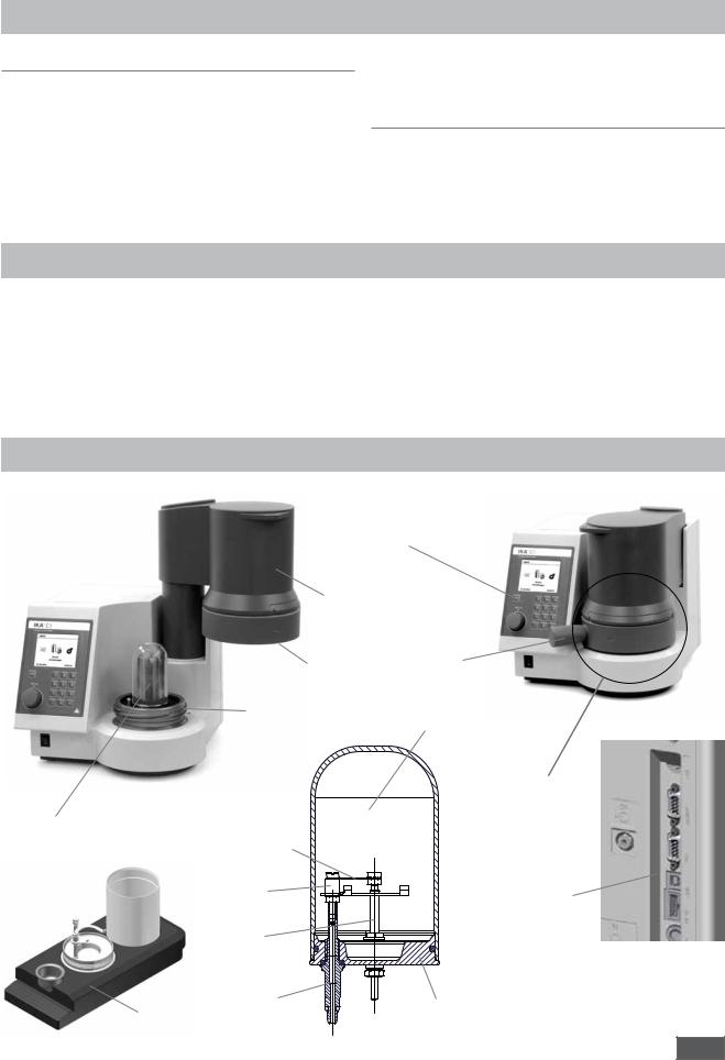
Description of the system components
Controller unit with display, Multifunctional element and keybord
Manual, pivotable lift
|
|
Rotary |
|
Threaded nut |
handle |
|
Threaded base |
Sectional view |
|
inner vessel |
|
|
|
|
|
|
Measuring cell as |
|
|
a pressure vessel |
Inner vessel (IB) |
|
|
|
Ignition wire |
|
|
Crucible |
Interfaces on |
|
holder |
|
|
|
rear of the unit |
|
Ignition |
|
|
electrode |
|
|
Ground electrode |
Base |
|
C 1.1012 |
|
|
|
|
|
Organizer |
6 |
C1 |
092014 |
|
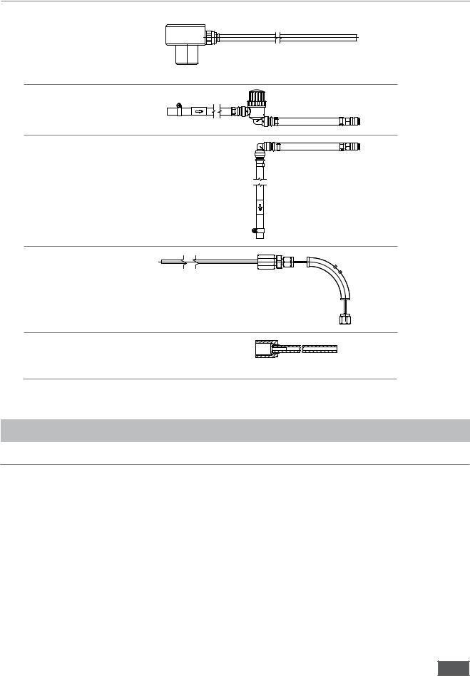
Hoses
• Discharge hose |
C1 |
|
(overflow) |
||
|
||
|
Cooler |
|
• Infow conduit |
Filtersieb 10μm |
|
|
Cooler |
(water in) |
max. 1,5 bar |
C1 |
• Return conduit |
C1 |
|
(water out) |
|
|
Cooler |
• Venting hose |
Exhaust |
C1 |
|
||
|
air |
(degas) |
|
|
|
|
|
SW8 |
• Connection tube |
Pressure reducer C29 |
Adapter |
C1 |
|
SW10 |
|
|
|
|
(O2) |
|
|
|
|
Commissioning
Place of installation
A constant ambient temperature is an important requirement |
For operation of the system the following must be available at the |
||
for ensuring the high measuring accuracy of the system. The |
place of installation: |
||
following conditions must therefore be fulfi lled at the place of |
- A power supply corresponding to the nameplates on the system |
||
installation: |
components, |
||
• |
No direct solar radiation |
- An oxygen supply (99.95 % pure oxygen, quality 3.5; pressure |
|
30 bar) with pressure gauge. |
|||
• |
No draughts (e.g. beside windows, doors, air conditioning) |
||
|
|||
•Su cient distance to radiators and other heat sources A shut-off valve for the oxygen supply must be installed. Observe
•The minimum distance between the wall and the rear side the instructions on handling oxygen given in the chapter „Safety
of the device must be at least 25 cm.
•The system must not have laboratory hardware such as shelves, wire ducts, ring lines, etc. installed above it.
•The (constant) room temperature should be around
20 °C ... 25 °C.
•The system must be set up on a horizontal surface.
instructions“.
Observe the instructions on handling oxygen given in the chapter „Safety instructions“. Please read these operating instructions carefully. IKA® consider themselves responsible for the safety, reliability and performance of the appliance only when
•the device has been operated in accordance with the operating instructions
•the specifi cations for the place of installation have been met.
7
C1 092014
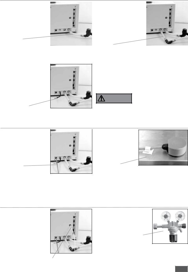
Cooler connection
1. Connect the infow pipe to the |
|
2. Connect the return pipe to the |
|
quick coupling to the „water |
|
quick coupling to the „water |
|
in“ (on the calorimeter) port. |
|
out“ (on the calorimeter) port. |
|
Connect the other end of the |
|
Connect the other end to |
|
radiator side of „water out“ |
|
„water in“ (on the cooler) and |
|
and tighten the hose clamp. |
|
tighten the hose clamp. |
|
Infow pipe |
|
|
|
|
|
Return pipe |
|
Venting hose connection |
|
|
|
1.Screw the venting hose to to „degas“ screw coupling
(SW8; on the calorimeter) and lay the free end in the extractor. Connect the free end to a gas scrabber gadget.
Venting hose
Observe the applicable safety regulations..
The combustion gases are vented from the decompstion vessel after each combustion test on the vent hose. The vent hose must not be kinked or pinched during installation.
DANGER |
Combustion gases are dangerous |
to health, so the venting hose |
|
|
must be connected to a suitable |
|
gas cleaning and extraction. |
Drain hose connection
1. Insert the drain hose fully into |
|
2. Secure the hose end with |
|
an attachable adhesive |
|
the „tap-water“ connection |
|
|
|
protection. |
|
(on the calorimeter). Lay the |
|
|
|
The hose end must always |
|
other end of the drain hose to |
|
|
the cooler fller neck. |
|
have free access of air and |
|
|
never immerse themselves |
|
|
in the cool water! |
Drain hose |
|
Cooler |
3. Do not use distilled or demineralized water (increased risk of corrosion)! Fill the cooler according to the cooler operating instructions. is recommended in drinking tap water quality. Mix in (max. 1 ml for 4-5l of water) of the supplied water additive. Thus, the durability of the water is improved..
4. Adjust the cooler temperature corresponding to the calorimeter operating temperature.
Oxygen supply connection
1.Insert the connection tube fully into the coupling („O2 in“; on the calorimeter) and connect the free end on the pressure
reducer IKA C29 (possibly |
|
with the C29 adapter, inclu- |
|
ded with). |
IKA C29 Pressure reducer |
Connection tube allowable operating pressure 40 bar
8
C1 092014
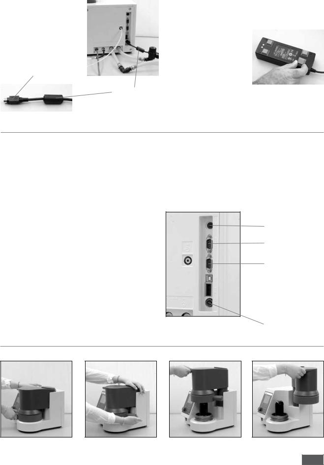
Power supply unit connection
1. Connect the power supply |
|
The desktop power supply (scope of delivery) must not be placed |
||
|
||||
|
fat on the laboratory table. It must be protected against moisture |
|||
connecting cable (24V) |
|
and water penetration and must not be wet. |
||
NOTE: Note the correct inser- |
|
2. Tape the supplied rubber feet |
|
|
tion position (fat side |
|
to the power supply. |
|
|
of the connector |
|
Place the power supply on the |
|
|
pointing to the right). |
|
rubber feet. |
|
|
|
|
|
Connect the connection cable |
|
|
|
|
to the DC power supply to |
|
fat side of the connector |
|
your supply network |
|
|
|
|
|
(100-240V AC 50/60Hz). |
|
|
|
|
||
|
|
|
|
|
|
|
Connecting cable |
||
|
|
|
|
|
Connection of peripherals
Heating: Control output for the connection of the IKA ® heating.
Scale: RS232 interface for connection of a scale (Mettler, Ohaus, Sortorius, Kern)
Interface parameters: Baud rate: 1200 Data its: 7 Parity: odd Stop its: 1 Handshake: none
PC/Printer: RS232 interface for connecting a PC to control the C1 (CalWin C6040) or a printer to output the measurement data.
Interface parameters:
USB-B: USB device interface for connection the calorimeters to the PC (CalWin C6040).
The connection simulates a serial interface on the PC.
Installation:
After the C1 was connected with the supplied data cable to the PC, the C1 tells the Windows operating system, which device driver is required.
This driver can be downloaded from the IKA website.
Find your driver at the following website: http://www.ika.com/ika/lws/download/stmcdc.inf
Programming- (only for service) interface:
24V= |
24V Voltage input for the included power |
|
supply table. |
Heating (ext)
Scale (balance)
PC / Printer (PC)
 USB-B (USB)
 Programming (Prog) interface
24V =
Handling the unit
1. Opening the unit
1 |
|
h |
h |
|
Q
Q2
The closing of the unit in the reverse order
9
C1 092014

2. Removing the inner vessel |
3. Removing the inner vessel base |
Inserting the inner vessel takes place in the reverse order
h
Q
4. Switch on the device
h
Open the device and switch the device on and off with the front power switch.
h
Control unit with display
Esc button
Multifunction element
Display
Numbers bloc
Del button
Display: View system information, test data, as well as menus and dialog boxes for the data input
Numbers bloc: Entering numbers and decimal points
Del button: Deleting an entered character string to the left of the cursor (eg the weight of a combustion sample)
Multifunction element
Made possible by turning the scroll and select menu items, as well as by pressing the Change and confrm input values
Esc button: The Esc-(Escape) function is active in the menu structure, the input window and input felds.
•In the menu structure (if any) change to the parent menu
•In the input window is changed to the higher level menu structure
•When the ESC button is pressed in an editable field, the editing is finished and the original value is restored.
10
C1 092014
Dialog box
The dialog boxes are equipped with the following elements:
|
|
|
Editable |
Menu-heading |
Selected menu item |
Scrollbar |
input field |
|
(blue) |
(yellow) |
Status field
Menu options resp. user notification
Menu-heading:
The name of the currently displayed window
Selected menu item:
The blue background (cursor) marks the selected item. The position can be changed by
turning the multifunction element.
Scrollbar: If a menu window more entries can be displayed as the current is displayed a scrollbar.
Turn the multi-function element, the other menu items are visible.
User notifications:
Some windows have a feld in the user notes will be displayed.
Menu options:
They allow a „getting ahead“ from the current window.
In the following example, the most frequently displayed menu options are listed and described:
• „Break off“:
Closing a window, the changes made will not be accepted by the system.
Also possible using [ESC].
• ‚Back‘:
Closing a info window without information input values and return to the parent menu.
Also possible using [ESC].
• ‚Accept‘:
Closing a window. Changes made are saved by the system.
• ‚Start‘:
Starting a measurement.
• ‚Details‘:
Detailed information during a running measurement.
• ‚Graph‘:
View graph during a running measurement.
Editable input field:
They can be enabled for value entry by pressing the multi-function element. The background color of the active feld is indicated in yellow. By using the numeric keys or by turning the multi-function element, the input values can be changed.
Status field:
Display the device status, which is important for the user and operation.
On confrmation |
On confrmation changes |
changes will not be |
will be applied |
applied |
|
11
C1 092014

System start
Switching on the system (in the open state)
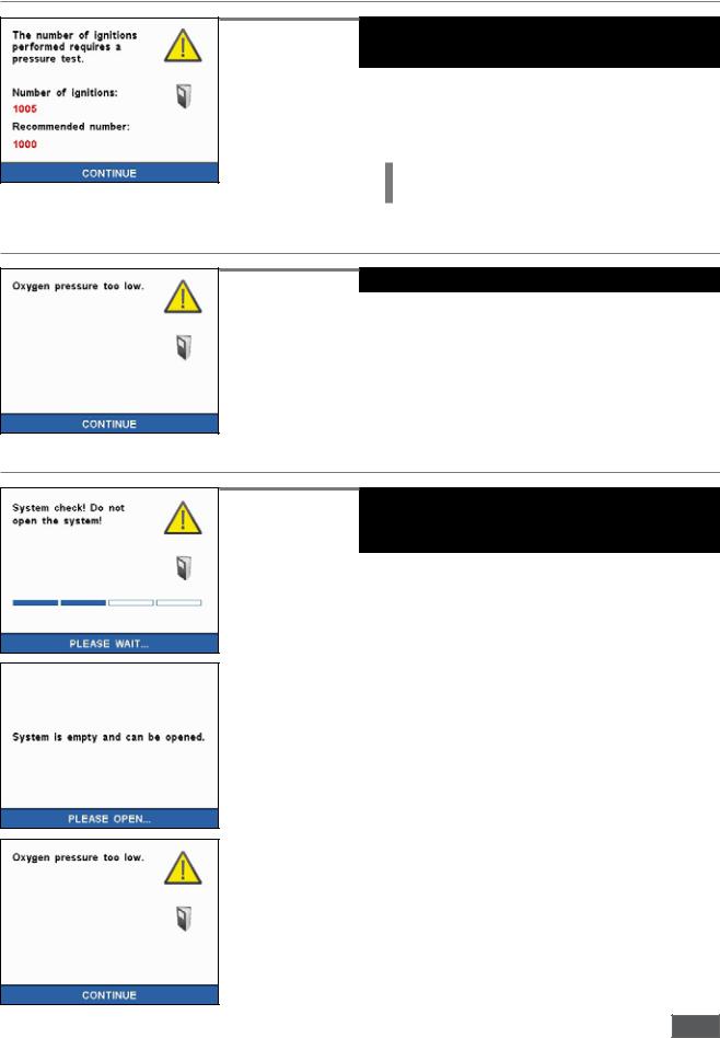
After switching on the calorimeter, frst the initial screen with the IKA ® logo, the calorimeter-type and the software and frmware version.
INFO: Upon initial system start, the menu language must be selected.
See capture - „Selection of language“
A menu language has been selected, the splash screen will change to the following information window:
INFO: Exceed the number of ignitions devices, the maximum recommended number of ignition, a pressure test must be performed with the device.
An additional information window is displayed. See capture - „Pressure test“
INFO: If the oxygen pressure is too low, a corresponding user information is displayed.
See capture - „Oxygen pressure too low“
By an verifcation (pressing the multifunction element) another user information on the proper use of the system is shown.
Refer to the chapter „Care and Maintenance“.
INFO: When the system is closed, a purge routine is started.
See capture - „System check“
INFO: Has been selected in the settings menu under accessories heating option, but this is not detected, user information is displayed.
See capture - „Heating detection - System start“
Selection of language
12
C1 092014
Pressure test
Oxygen pressure
System check
A pressure test must be performed after a decomposition vessel has reached or exceeded the recommended number of ignition cycles.
Once the pressure test has been performed a release code can be entered to enable the unit to be used for further measurements. The warning message will then disappear. The enable code can be in the following screen, by pressing the „Next button“ to be entered.
INFO:Using the unit may be further worked.
Contact for performing the pressure test, the service department from IKA Works. Observe the safety instructions!
service@ika.de
Information screen: oxygen pressure is too low.
NOTE:
The calorimeter C1 required for functionality an oxygen pressure of at least 20 bar.
Reproducible measurements for a working pressure of 30 bar is required.
System start when the device is closed.
The system is brought through the system check in a safe and completely defated state. For this, the oxygen and water discharge is performed.
Here, the following information screen is displayed:
INFO:During the system check detected no oxygen or the oxygen pressure is too low, the following error message is displayed:
13
C1 092014
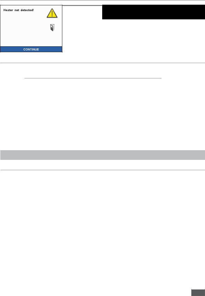
Heating detected
If the use of heating selected C1.20 (accessories) in the Setting menu, but this is not recognized, the following user information is displayed.
NOTE:
Check that the heater is correctly connected and turned on..
Factory settings
As delivered, the C1 calorimeter system is confgured as follows:
Settings:
• |
Menu: |
animated |
• |
Heating: |
off |
• |
Color palette: |
white |
• |
Disposable crucible: |
no |
• |
Key tones: |
on |
• |
Printer: |
off |
• |
Date device: |
01.01.2012 |
• |
Service Info: |
no |
• |
Time device: |
00:00:00 Uhr |
• |
Scale: |
off |
• |
Units: |
J/g |
|
|
|
Basic settings: |
|
|
|
|
|
• |
C-value IB1: |
0 |
• |
QExternally 1: |
50 |
• |
C-value IB2: |
0 |
• |
QExternally 2: |
0 |
• |
Reference calorific value: |
26457 |
• |
Controlled time: |
off |
• |
Start temperature: |
22°C |
• |
O2 rinsing: |
off |
• |
HO Combustible crucible: |
19839 |
• |
Cooling: |
on |
|
|
|
• |
Prolonged venting: |
0 |
Calorimetric measurements
Determination of gross calorific value
Test condition
Combustion is carried out in a calorimeter under specific conditions.
The IKA® C1 is filled with a weighed fuel sample, the fuel sample is ignited and the temperature increase in the calorimeter system measured.
The specifi c calorifi c value of the sample is calculated as follows:
•Weight of fuel sample
•Heat capacity (C-value) of calorimeter system
•Calculated temperature increase of water in the calorimeter system
For complete combust on the inner vessel is filled with pure oxygen (quality 3.5). The pressure of the oxygen atmosphere in the inner vessel is max. 40 bar.
The exact determinat on of the gross calorific value of a substance requires that the combust on proceed under precisely defined conditons. The applicable standards are based on the following assumptons:
•Depending on the start temperatur that is set, the temperature of the fuel before the combustion is 20 °C upto 30 °C.
•The water contained in the fuel before the combustion and the water that is formed when compounds comprising the fuel containing hydrogen undergo combustion is present in a liquid state.
•No oxidation of the atmospheric nitrogen has taken place.
•The gaseous products after combustion consist of oxygen, nitrogen, carbon dioxide, sulfur dioxide and the oxidation
products of the sample.
•Solid substances may be formed (for example ash).
Often, however, the combustion products that form the basis of the standards are not the only products that are formed. In such cases, an analysis of the fuel sample and the products of combustion are necessary to provide data for a correction calculation. The standard gross calorifi c value is then determined from the measured gross calorifi c value and the analysis data.
The gross calorifc value Ho is formed as the quotient of the amount of heat liberated upon total combustion of a solid or liquid fuel and the weight of the fuel sample. The compounds comprising the fuel that contain water must be present in liquid state after the combustion.
The heat value Hu is equal to the gross calorifi c value less the energy of condensation of the water that was contained in the fuel and was formed by the combustion. The heat value is the more important quantity for technical purposes, since in all important technical applications, the heat value is the only quantity that can be evaluated in terms of energy.
For information on the fundamental principles of calculation for gross calorific value and heat value, please refer to the applicable standards (for example: DIN 51 900; ASTM D 240;ASTM D 1989, ISO 1928).
14
C1 092014
 Loading...