


INSTRUCTION MANUAL
VHF TRANSCEIVER
iF3062T/S
UHF TRANSCEIVER
iF4062T/S
This device complies with Part 15 of the FCC Rules. Operation is subject to the condition that this device does not cause harmful interference.

IMPORTANT
READ ALL INSTRUCTIONS carefully and com-
pletely before using the transceiver.
SAVE THIS INSTRUCTION MANUAL — This
instruction manual contains important operating instructions for the IC-F3062T/S VHF TRANSCEIVERS and IC-F4062T/S UHF TRANSCEIVERS.
Icom, Icom Inc. and the 
 logo are registered trademarks of Icom Incorporated (Japan) in the United States, the United Kingdom, Germany, France, Spain, Russia and/or other countries.
EXPLICIT DEFINITIONS
WORD |
DEFINITION |
|
RWARNING |
Personal injury, fire hazard or electric shock |
|
may occur. |
||
|
Equipment damage may occur. |
|
CAUTION |
||
NOTE |
If disregarded, inconvenience only. No risk |
|
of personal injury, fire or electric shock. |
||
|
||
|
|
i

TABLE OF CONTENTS
IMPORTANT ........................................................................ |
i |
|
EXPLICIT DEFINITIONS ..................................................... |
i |
|
TABLE OF CONTENTS ...................................................... |
ii |
|
PRECAUTIONS ................................................................. |
iii |
|
1 |
ACCESSORIES ......................................................... |
1–3 |
|
■ Supplied accessories ................................................. |
1 |
|
■ Accessory attachments .............................................. |
1 |
2 |
PANEL DESCRIPTION ........................................... |
4–10 |
|
■ Front panel ................................................................. |
4 |
|
■ Function display ......................................................... |
6 |
|
■ Programmable function keys ..................................... |
7 |
3 |
BASIC OPERATION .............................................. |
11–16 |
|
■ Turning power ON .................................................... |
11 |
|
■ Channel selection .................................................... |
12 |
|
■ Call procedure .......................................................... |
12 |
|
■ Receiving and transmitting ....................................... |
13 |
|
■ User set mode .......................................................... |
16 |
|
■ Scrambler function ................................................... |
16 |
4 |
BIIS OPERATION .................................................. |
17–27 |
|
■ Setting example ....................................................... |
17 |
|
■ Receiving a call ........................................................ |
17 |
|
■ Transmitting a call .................................................... |
19 |
|
■ Receiving a message ............................................... |
21 |
|
■ Transmitting a status ................................................ |
23 |
|
■ Transmitting an SDM (Short Data Message) |
............ 24 |
|
■ Position data transmission ....................................... |
25 |
|
■ Printer connection .................................................... |
26 |
|
■ Digital ANI ................................................................ |
26 |
|
■ Auto emergency transmission .................................. |
26 |
|
■ Stun function ............................................................ |
26 |
|
■ BIIS indication .......................................................... |
27 |
|
■ Priority A channel selection ...................................... |
27 |
5 |
BATTERY CHARGING .......................................... |
28–32 |
|
■ Caution ..................................................................... |
28 |
|
■ Optional battery chargers ......................................... |
30 |
6 |
BATTERY CASE ......................................................... |
33 |
7 |
SWIVEL BELT CLIP .............................................. |
34–35 |
|
■ MB-93 contents ........................................................ |
34 |
|
■ Attaching .................................................................. |
34 |
|
■ Detaching ................................................................. |
35 |
8 |
OPTIONS ............................................................... |
36–38 |
9 |
DOC ....................................................................... |
39–41 |
1
2
3
4
5
6
7
8
9
ii

PRECAUTIONS
RCAUTION! NEVER hold the transceiver so that the antenna is very close to, or touching exposed parts of the body, especially the face or eyes, while transmitting. The transceiver will perform best if the microphone is 5 to 10 cm away from the lips and the transceiver is vertical.
RCAUTION! NEVER operate the transceiver with a headset or other audio accessories at high volume levels.
RCAUTION! NEVER short the terminals of the battery pack.
DO NOT push [PTT] when not actually desiring to transmit.
AVOID using or placing the transceiver in direct sunlight or in areas with temperatures below –25°C or above +55°C.
The basic operations, transmission and reception of the transceiver are guaranteed within the specified operating temperature range. However, the LCD display may not be operated correctly, or show an indication in the case of long hours of operation, or after being placed in extremely cold areas.
DO NOT modify the transceiver for any reason.
KEEP the transceiver from the heavy rain, and Never immerse it in the water. The transceiver construction is water resistant, not waterproof.
The use of non-Icom battery packs/chargers may impair transceiver performance and invalidate the warranty.
iii
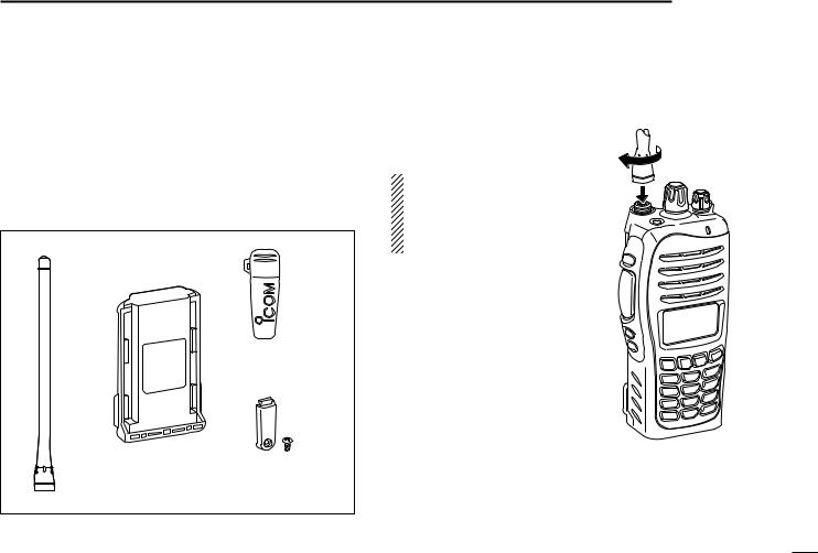
■ Supplied accessories
The following accessories are supplied: |
Qty. |
q Flexible antenna …………………………………………… 1 |
|
w Battery pack ……………………………………………… 1 |
|
e Belt clip …………………………………………………… 1 |
|
r Connector cover (with screw) ……………………… 1 set |
|
Some accessories are not supplied with depending on versions.
q |
w |
e |
r
ACCESSORIES |
1 |
|
|
|
|
||
|
|
||
|
|
||
■ Accessory attachments |
|
|
|
1 |
|||
DFlexible antenna
Connect the supplied flexible antenna to the antenna connector.
CAUTION!
• NEVER HOLD by the antenna when carrying the transceiver.
• Transmitting without an antenna may damage the transceiver.
1

1 ACCESSORIES
ï Battery pack
To attach the battery pack:
Slide the battery pack in the direction of the arrow (q), then lock it with the battery release button.
•Slide the battery pack until the battery release button makes a ‘click’ sound.
To release the battery pack:
Slide the battery release button in the direction of the arrow (w) as shown below. The battery pack is then released.
NEVER release or attach the battery pack when the transceiver is wet or soiled. This may result water or dust getting into the transceiver/battery pack and may result in the transceiver being damaged.
Battery release button
q

 w
w
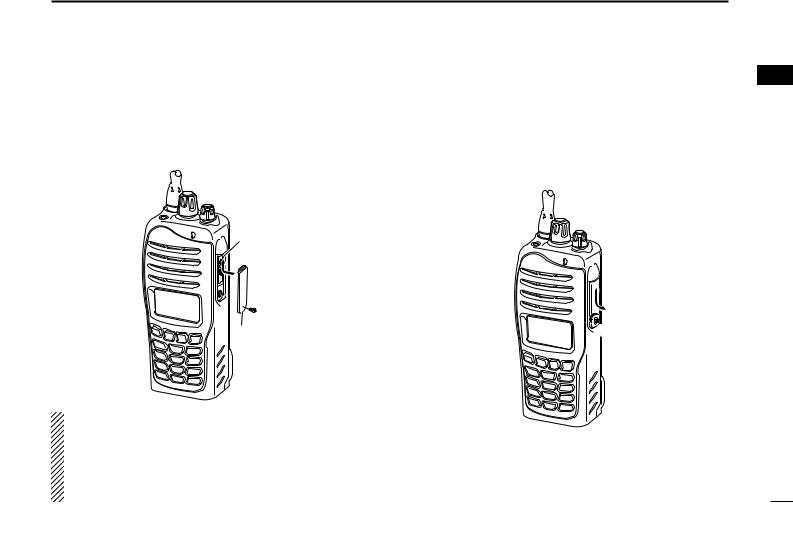
DBelt clip
To attach the belt clip:
q Release the battery pack if it is attached.
wSlide the belt clip in the direction of the arrow until the belt clip is locked and makes a ‘click’ sound.
To detach the belt clip:
q Release the battery pack if it is attached.
wPinch the clip (q), and slide the belt clip in the direction of the arrow (w).
w
q


2
ï Connector cover
Attach the connector cover when the optional speaker-micro- phone or head-set is not used.
To attach the connector cover:
q Insert the connector cover into the multi-connector. w Tighten the screw.
Multiconnector
q
 w
w
Connector cover
CAUTION!
Attach the connector cover when the optional speakermicrophone is not used.
Otherwise the terminals of the multi-connector may be shorted by metal object, etc., and this could damage the transceiver.
ACCESSORIES 1
1
To detach the connector cover:
q Unscrew the screw using a phillips screwdriver.
w Detach the connector cover for the speaker-microphone or head-set connector.
w
q
3
 2 PANEL DESCRIPTION
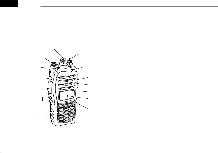
■ Front panel
|
q |
w |
!2 |
|
|
e |
!1 |
|
|
r |
!0 |
|
|
|
Speaker |
t |
Microphone |
|
|
y |
o |
u |
i |
|
q ROTARY SELECTOR
Rotate to select the pre-programmed memory channels or the operating zone.
(Depending on the pre-setting)
w ANTENNA CONNECTOR
Connects the supplied antenna.
e DEALER-PROGRAMMABLE KEY [Emer]
Desired functions can be programmed by your dealer. (( p. 7))
r DEALER-PROGRAMMABLE KEY [Side1]
Desired functions can be programmed by your dealer. (( p. 7))
t PTT SWITCH [PTT]
Push and hold to transmit; release to receive.
y DEALER-PROGRAMMABLE KEYS [Side2]/[Side3]
Desired functions can be programmed independently by your dealer. (( p. 7))
u 10-KEYPAD (Depending on version) The keypad allows you to enter digits to:
•Select memory channels
•Select tone channels
•Select DTMF codes (during transmit)
•Set TX codes
•Set BIIS status number
•Input text message for SDM operation.
•Start up with the password
4

PANEL DESCRIPTION 2
i DEALER-PROGRAMMABLE KEYS [P0] to [P3]
Desired functions can be programmed independently by your dealer. (( p. 7))
o FUNCTION DISPLAY
2
!1BUSY/TRANSMIT INDICATOR
Lights green while receiving a signal, or when the squelch is open.
Lights red while transmitting.
Displays a variety of information such as an operating |
!2VOLUME CONTROL [VOL] |
||
channel number/name, 2/5-tone code, DTMF numbers, |
Rotate to turn the power ON/OFF and adjusts the audio |
||
selected function, etc. |
level. |
||
!0MULTI-CONNECTOR |
|
||
Connect an optional speaker-microphone. |
|
||
|
|
|
|
|
|
|
|
 Connector cover
NOTE: Attach the connector cover when the optional speak- er-microphone is not used.
See (( p. 3)) for details.
5
2 PANEL DESCRIPTION
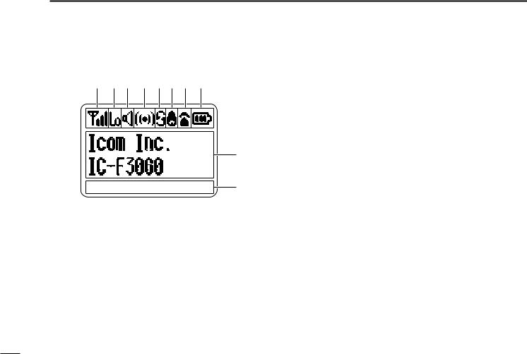
■ Function display
q w e r t y u i
o
CALA TXCU TXC SET |
!0 |
q SIGNAL STRENGTH INDICATOR
Indicates relative signal strength level.
w LOW POWER INDICATOR
Appears when low output power is selected.
e AUDIBLE INDICATOR
Appears when the channel is in the ‘audible’ (unmute) condition.
Appears when the specified 2/5-tone/BIIS code is received.
r COMPANDER INDICATOR
Appears when the compander function is activated.
t SCRAMBLER INDICATOR
Appears when the voice scrambler function is activated.
y BELL INDICATOR
Appears/blinks when the specific 2/5-tone/BIIS code is received, according to the pre-programming.
u CALL CODE MEMORY INDICATOR
Appears when the call code memory is selected.
i BATTERY INDICATOR
Appears or blinks when the battery power decreases to a specified level.
o ALPHANUMERIC DISPLAY
Displays an operating channel number, channel name, Set mode contents, DTMF code, etc.
The indication mode can be selected from 1 line or 2 lines. Ask your dealer for details.
•In this instruction manual, the LCD illustration is described using the 2 lines indication mode.
!0KEY INDICATOR
Indicate the programmed function of the front panel keys ([P0], [P1], [P2] and [P3]).
6
■ Programmable function keys
The following functions can be assigned to [Emer], [Side1], [Side2], [Side3], [P0], [P1], [P2] and [P3] programmable function keys.
Consult your Icom dealer or system operator for details concerning your transceivers programming.
If the programmable function names are bracketed in the following explanations, the specific key is used to activate the function depends on the programming.
CH UP AND DOWN KEYS “UP” “DOWN”
Push to select an operating channel.
Push to select a transmit code channel after pushing [TX Code CH Select].
Push to select a DTMF channel after pushing [DTMF Autodial].
Push to select a scan group after pushing and holding [Scan A Start/Stop]/[Scan B Start/Stop].
Push to select a BIIS code, status number or SDM after pushing [Digital Button].
ZONE KEY “ZONE”
Push this key, then push [CH Up] or [CH Down] to select the desired zone.
PANEL DESCRIPTION 2
What is “zone”?— The desired channels are assigned |
2 |
into a zone according to the intended use for grouping. For example, ‘Staff A’ and ‘Staff B’ are assigned into a “Business” zone, and ‘John’ and ‘Cindy’ are assigned into a “Private” zone.
SCAN A KEY “SCNA”
This key’s operation depends on the Power ON Scan setting.
When the power ON scan function is turned OFF;
Push to start and cancel scanning operation. In case of transmission during scan, cancels scanning.
When the power ON scan function is turned ON;
Push to pause scanning., then resumes scanning after passing a specified time period. In case of transmission during scan, scanning will be cancelled.
Push and hold this key for 1 sec. to indicate the scan group, then push [CH Up] or [CH Down] to select the desired group.
SCAN B KEY “SCNB”
Push to start and cancel scanning operation. In case of transmission during scan, pauses scanning. Scanning resumes after passing a specified time period.
Push and hold this key for 1 sec. to indicate the scan group, then push [CH Up] or [CH Down] to select the desired group.
7

2 PANEL DESCRIPTION
SCAN ADD/DEL (TAG) KEY “SCAD”
Push to add or delete the selected channel to/from the scan group.
PRIO A/B KEYS “PRA” “PRAR” “PRB” “PRBR”
Push to select Priority A or Priority B channel.
Push and hold [Prio A (Rewrite)] to rewrite the Prio A channel.
MR-CH 1/2/3/4 KEYS “CH1” “CH2” “CH3” “CH4”
Push to select an operating channel directly.
MONI (AUDI) KEY “MON”
Activates one of (or two of) the following functions on each channel independently: (PMR or BIIS PMR operation only)
•Push and hold to un-mute the channel (audio is emitted; ‘Audible’ condition).
•Push to mute the channel (sets to ‘Inaudible’ only).
•Push to un-mute the channel (sets to ‘Audible’ only).
•Push after the communication is finished to send a ‘reset code.’
NOTE: The un-mute condition (‘Audible’ condition) may automatically return to the mute condition (‘Inaudible‘ condition) after a specified period depending on programming.
LIGHT KEY “LIGT”
Push to turn the transceiver’s backlight ON temporarily only when the backlight function is turned OFF in user set mode.
LOCK KEY “LOCK”
Push and hold for 1 sec. to electronically lock all programmable keys except the following:
[Call] (incl. Call A and Call B), [Moni(Audi)] and [Emergency].
Push and hold for 1 sec. again to turn the lock function OFF.
HIGH/LOW KEY “H/L”
Push to select the transmit output power temporarily or permanently, depending on the pre-setting.
• Ask your dealer for the output power level for each selection.
C.TONE CH ENT KEY “TSEL”
Push to select the continuous tone channel using [CH Up]/[CH Down] to change the tone frequency/code setting. The selected channel remains set as the continuous tone channel until another channel is designated as such.
TALK AROUND KEY “TA”
Push to turn the talk around function ON and OFF.
•The talk around function equalizes the transmit frequency to the receive frequency for transceiver-to-transceiver communication.
WIDE/NARROW KEY “W/N”
Push to toggle the IF bandwidth between wide and narrow.
•The wide passband width can be selected from 25.0 or 20.0 kHz using the CS-F3060 CLONING SOFTWARE. (PMR or BIIS PMR operation only) Ask your Dealer for details.
8

DTMF AUTODIAL KEY “DTMA”
Push to enter the DTMF channel selection mode. Then select the desired DTMF channel using [CH Up]/[CH Down].
After selecting the desired DTMF channel, push this key to transmit the DTMF code.
RE-DIAL KEY “DTMR”
Push to transmit the last-transmitted DTMF code.
CALL KEYS “CALL” “CALA” “CALB”
Push to transmit a 2/5-tone/BIIS ID code.
•Call transmission is necessary before you call another station depending on your signaling system.
•[Call A] and/or [Call B] may be available when your system employs selective ‘Individual/Group’ calls. Ask your dealer which call is assigned to each key.
EMERGENCY KEY “EMR”
Push and hold for a specified period to transmit an emergency call.
When [Emergency Single (Silent)] or [Emergency Repeat (Silent)] is pushed, an emergency call is transmitted without a beep emission and LCD indication change.*
•If you want to cancel the emergency call, push (or push and hold) the key again before transmitting the call.
•The emergency call is transmitted one time only or repeatedly until receiving a control code depending on the pre-setting.
*BIIS PMR operation only
PANEL DESCRIPTION 2
SURVEILLANCE KEY “SURV” |
|
Push to turn the surveillance function ON or OFF. |
2 |
When this function is turned ON, the beep is not emitted and |
the LCD backlight does not light when a signal is received or a key is pushed, etc.
TX CODE ENTER KEY “TXCE”
(PMR or BIIS PMR operation only)
Push to enter the ID code edit mode directly, for both 5-tone and BIIS. Then set the desired digit using [CH Up]/ [CH Down] or 10-keypad*. (( p. 14))
*IC-F3062T/IC-F4062T (10-key type) only
TX CODE CHANNEL SELECT KEY “TXC”
Push to enter the ID code channel selection mode directly. Then set the desired channel using [CH Up]/[CH Down]. (( p. 14))
During ID code channel selection mode, push for 1 sec. to enter the ID code edit mode for 5-tone and BIIS. Then set the desired digit using [CH Up]/[CH Down] or 10-keypad*. (( p. 14))
*IC-F3062T/IC-F4062T (10-key type) only
TX CODE CHANNEL UP/DOWN KEYS “TXCU” “TXCD”
Push to select a TX code channel directly.
9

2 PANEL DESCRIPTION
ID-MR SELECT KEY “IDMS”
(PMR or BIIS PMR operation only)
Recalls detected ID codes.
•Push this key, then select the ID code using [CH Up]/[CH Down].
•Up to 5 ID’s are memorized.
Push and hold to erase the selected ID’s.
SCRAMBLER FUNCTION “SCR”
Push to toggle the voice scrambler function ON and OFF.
COMPANDER KEY “COMP”
Push to toggle the compander function ON and OFF.
The compander function reduces noise components from the transmitting audio to provide clear communication.
USER SET MODE KEY “SET”
Push and hold to enter user set mode.
•During user set mode, push this key to select an item, and change the value or condition using push [CH Up]/[CH Down].
Push and hold this key again to exit user set mode.
User set mode is also available via the ‘Power ON function.’ Refer to (( p. 16)) also.
OPT OUT KEYS “OP1” “OP2” “OP3”
Push to control the output signal level of the optional ports in the optional unit connector.
OPT MOMENTARY KEYS “O1M” “O2M” “O3M”
Push and hold to control the output signal level of the optional ports in the optional unit connector.
DIGITAL BUTTON KEY “BIFN”
(BIIS operation only)
Push to select the call ID list, transmit message and standby condition. Toggles between queue channel and received message record indication after queue channel is selected.
Push and hold to select queue channel indication.
STATUS UP/DOWN KEYS “BIUP” “BIDN”
(BIIS operation only)
While in the standby condition, push to display the transmit status indication and select a status number.
When a received SDM is displayed, push to cancel the automatic scroll and scroll the message manually.
When an SDM that contains more than 12 characters is displayed, push to scroll the message manually.
10
■ Turning power ON
Prior to using the transceiver for the first time, the battery pack must be fully charged for optimum life and operation. (( p. 30))
q Rotate [VOL] to turn the power ON.
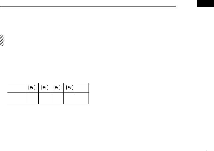
wIf the transceiver is programmed for a start up password, input the digit codes as directed by your dealer.
•10-keypad can be used for password input depending on version:
•The keys in the table below can be used for password input:
•The transceiver detects numbers in the same block as identical. Therefore “01234” and “56789” are the same.
KEY |
|
|
|
|
(Side3) |
|
NUMBER |
0 |
1 |
2 |
3 |
4 |
|
5 |
6 |
7 |
8 |
9 |
||
|
eWhen the “PASSWORD” indication does not clear after inputting 4 digits, the input code number may be incorrect. Turn the power off and start over in this case.
BASIC OPERATION 3 
DBattery type selection |
2 |
|
|
The battery type must be selected according to the attaching |
3 |
battery type when tuning the transceiver ON. |
|
While pushing and holding [Emer] and [PTT], rotate [VOL] to toggle the attaching battery type.
•After the display appears, release [Emer] and [PTT].
•“DRY BATT” is displayed for about 3 sec. then “Lo” appears when the battery case operation is selected.
•“LI-ION” is displayed for about 3 sec. when the Lithium-ion battery operation is selected.
•This operation may not be available depending on the pre-setting. Ask your dealer for details.
11
 Loading...