


 Loading...
Icom IC-F3162T, IC-F3162S, IC-F4162DT, IC-F3162DT, IC-F4162S Manual
...INSTRUCTION MANUAL
VHF TRANSCEIVER
iF3162T/S
iF3162DT/DS
UHF TRANSCEIVER
iF4162T/S
iF4162DT/DS
The photo shows the 10-key version UHF transceiver.

IMPORTANT
READ ALL INSTRUCTIONS carefully and com-
pletely before using the transceiver.
SAVE THIS INSTRUCTION MANUAL — This
instruction manual contains important operating instructions for the IC-F3162T, IC-F3162S, IC-F3162DT and IC-F3162DS VHF TRANSCEIVERS and IC-F4162T, IC-F4162S, ICF4162DT and IC-F4162DS UHF TRANSCEIVERS.
 See the operating guide for details of BIIS, MDC, LTR®
  and Digital system operations. Ask your dealer for details.
EXPLICIT DEFENITIONS
WORD |
DEFINITION |
|
RDANGER |
Personal death, serious injury or an explo- |
|
sion may occur. |
||
|
||
RWARNING |
Personal injury, fire hazard or electric |
|
shock may occur. |
||
|
||
CAUTION |
Equipment damage may occur. |
|
NOTE |
If disregarded, inconvenience only. No risk |
|
of personal injury, fire or electric shock. |
||
|
||
|
|
Icom, Icom Inc. and the Icom logo are registered trademarks of Icom Incorporated (Japan) in Japan, the United States, the United Kingdom, Germany, France, Spain, Russia and/or other countries.
LTR is a registered trademark of the E.F.Johnson Company.
All other products or brands are registered trademarks or trademarks of their respective holders.

PRECAUTIONS
R CAUTION! NEVER hold the transceiver so that the antenna is very close to, or touching exposed parts of the body, especially the face or eyes, while transmitting. The transceiver will perform best if the microphone is 5 to 10 cm away from the lips and the transceiver is vertical.
R CAUTION! NEVER operate the transceiver with a headset or other audio accessories at high volume levels.
R CAUTION! NEVER short the terminals of the battery pack.
DO NOT modify the transceiver. The transceiver warranty does not cover any problems caused by unauthorized modification.
KEEP the transceiver away from the heavy rain, and Never immerse it in the water. The transceiver meets IP55* requirements for dust-protection and water jet resistance.
However, once the transceiver has been dropped, dustprotection and water jet resistance cannot be guaranteed due to the fact that the transceiver may be cracked, or the waterproof seal damaged, etc.
R CAUTION! NEVER use non-Icom battery packs/ chargers to prevent the loss of the transceiver’s good performance and warranty.
DO NOT push [PTT] when not actually desiring to transmit.
DO NOT use or place the transceiver in direct sunlight or in areas with temperatures below –25°C or above +55°C.
The basic operations, transmission and reception of the transceiver are guaranteed within the specified operating temperature range. However, the LCD display may not operate correctly, or show an indication in the case of long hours of operation, or after being placed in extremely cold areas.
*Only when the supplied battery pack, flexible antenna and connector cover are attached.
Icom optional equipment are designed for optimal performance when used with this transceiver. We are not responsible for the transceiver being damaged or any accident caused when using non-Icom optional equipment.
1
2
3
4
5
6
7
8
9
10
11
12
13
14
15
16
ii

VOICE CODING TECHNOLOGY
The AMBE+2™ voice coding Technology embodied in this product is protected by intellectual property rights including patent rights, copyrights and trade secrets of Digital Voice Systems, Inc. This voice coding Technology is licensed solely for use within this Communications Equipment. The user of this Technology is explicitly prohibited from attempting to extract, remove, decompile, reverse engineer, or disassemble the Object Code, or in any other way convert the Object Code into a human-readable form. U.S. Patent Nos.
#5,870,405, #5,826,222, #5,754,974, #5,701,390, #5,715,365, #5,649,050, #5,630,011, #5,581,656, #5,517,511, #5,491,772, #5,247,579, #5,226,084 and #5,195,166.
iii

TABLE OF CONTENTS
IMPORTANT........................................................................... |
i |
|
EXPLICIT DEFENITIONS...................................................... |
i |
|
PRECAUTIONS.................................................................... |
ii |
|
VOICE CODING TECHNOLOGY......................................... |
iii |
|
TABLE OF CONTENTS....................................................... |
iv |
|
1 |
ACCESSORIES............................................................ |
1–3 |
|
■ Supplied accessories.................................................... |
1 |
|
■ Accessory attachments................................................. |
1 |
2 |
PANEL DESCRIPTION.............................................. |
4–10 |
|
■ Front panel.................................................................... |
4 |
|
■ Function display............................................................ |
5 |
|
■ Programmable function keys......................................... |
6 |
3 |
BASIC OPERATION................................................ |
11–17 |
|
■ Turning power ON....................................................... |
11 |
|
■ Channel selection....................................................... |
12 |
|
■ Call procedure............................................................. |
13 |
|
■ Receiving and transmitting.......................................... |
13 |
|
■ User set mode............................................................. |
16 |
|
■ Emergency transmission............................................. |
16 |
|
■ Man Down Emergency Call........................................ |
16 |
|
■ Scrambler function...................................................... |
17 |
|
■ Stun function............................................................... |
17 |
|
■ Automatic Key Lock function....................................... |
17 |
|
■ Priority A channel selection........................................ |
17 |
|
■ Forced Narrow function............................................... |
17 |
4 |
BATTERY CHARGING............................................. |
18–23 |
|
■ Caution....................................................................... |
18 |
|
■ Optional battery chargers........................................... |
20 |
5 |
BATTERY CASE............................................................ |
23 |
|
■ Optional battery case (BP-240).................................. |
23 |
6 |
SWIVEL BELT CLIP................................................. |
24–25 |
|
■ MB-93 contents........................................................... |
24 |
|
■ To attach...................................................................... |
24 |
|
■ To detach..................................................................... |
25 |
7 |
SPEAKER MICROPHONE............................................. |
26 |
|
■ Optional HM-169/170GP description.......................... |
26 |
|
■ To attach...................................................................... |
26 |
8 |
OPTIONS................................................................. |
27–30 |
9 |
DOC.......................................................................... |
31–32 |
1
2
3
4
5
6
7
8
9
10
11
12
13
14
15
16
iv
 1 ACCESSORIES
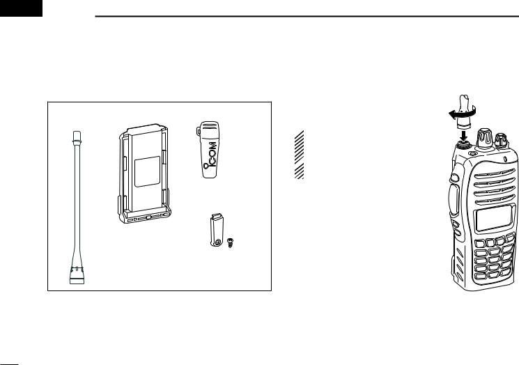
■ Supplied accessories
The following accessories are supplied.
Flexible |
Battery pack |
Belt clip |
antenna |
|
|
Connector cover (with screw)
■ Accessory attachments
D Flexible antenna
Connect the supplied flexible antenna to the antenna connector.
 CAUTION:
• NEVER HOLD the antenna when
carrying the transceiver.
 • Transmitting without an antenna may damage the transceiver.

D Battery pack
To attach the battery pack:
Slide the battery pack on the back of the transceiver in the direction of the arrow (q), then lock it with the battery release button.
•Slide the battery pack until the battery release button makes a ‘click’ sound.
To release the battery pack:
Push the battery release button in the direction of the arrow (w) as shown below. The battery pack is then released.
 NEVER release or attach the battery pack when the
transceiver is wet or soiled. This may result water or dust getting into the transceiver/battery pack and may result in  the transceiver being damaged.
Battery pack
q
|
Battery release |
w |
button |
|
 NOTE: Keep the battery pack terminals clean. It’s a good
  idea to clean the battery pack terminals once a week.
ACCESSORIES 1
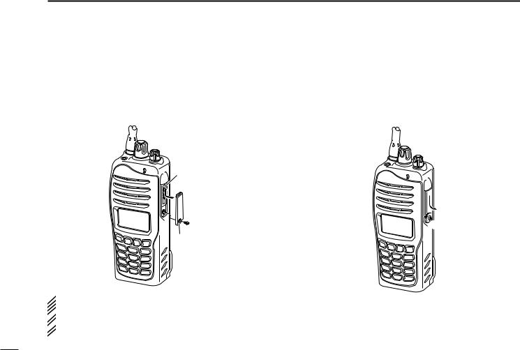
D Belt clip
To attach the belt clip:
q Release the battery pack if it is attached.
w Slide the belt clip in the direction of the arrow until the belt clip is locked and makes a ‘click’ sound.
To detach the belt clip:
q Release the battery pack if it is attached.
w Pinch the clip (q), and slide the belt clip in the direction of the arrow (w).
w
q


1
2
3
4
5
6
7
8
9
10
11
12
13
14
15
16
1 ACCESSORIES
D Connector cover
Attach the connector cover when the optional equipment is not used.
To attach the connector cover:
q Insert the connector cover into the multi-connector. w Tighten the screw.
To detach the connector cover:
q Unscrew the screw using a phillips screwdriver.
w Detach the connector cover for the optional equipment connector.
Multiconnector
q
w
w
q
Connector cover
 CAUTION:
Attach the connector cover when the optional equipment  is not used. Otherwise the terminals of the multi-connec-
  tor may be shorted by metal object, etc., and this could
  damage the transceiver.
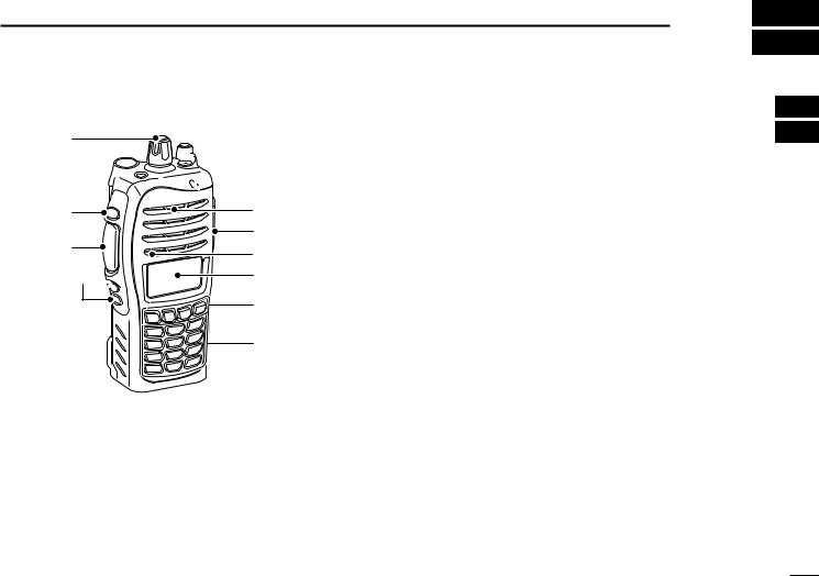
■ Front panel
q
w


 !2 e
!2 e


 !1
!1
r |
Speaker |
|
t |
!0 |
|
Microphone |
||
|
o
y


i
u
q ROTARY SELECTOR
Rotate to select the pre-programmed memory channels or the operating zone. (Depending on the pre-setting)
w ANTENNA CONNECTOR
Connects the supplied antenna. (p. 1)
e DEALER-PROGRAMMABLE KEY [EMR]
Desired function can be programmed by your dealer. (p. 6)
PANEL DESCRIPTION 2
r DEALER-PROGRAMMABLE KEY [Side1]
Desired function can be programmed by your dealer. (p. 6)
t PTT SWITCH [PTT]
Push and hold to transmit; release to receive.
y DEALER-PROGRAMMABLE KEYS [Side2]/[Side3]
Desired function can be programmed independently by your dealer. (p. 6)
u 10-KEYPAD (Depending on version) The keypad allows you to enter digits to:
•Select memory channels
•Select tone channels
•Select DTMF codes (during transmit)
•Set TX codes
•Start up with the password
iDEALER-PROGRAMMABLE KEYS [P0] to [P3]
Desired function can be programmed independently by your dealer. (p. 6)
o FUNCTION DISPLAY (p. 5)
Displays a variety of information such as an operating channel number/name, Set mode contents, DTMF code, selected function, etc.
1
2
3
4
5
6
7
8
9
10
11
12
13
14
15
16
2 PANEL DESCRIPTION
!0MULTI-CONNECTOR
Connect an optional equipment.
Connector cover
NOTE: Attach the connector cover when the optional equipment is not used.
See p. 3 for details.
!1BUSY/TRANSMIT INDICATOR
Lights green while receiving a signal, or when the squelch is open.
Lights red while transmitting.
!2VOLUME CONTROL [VOL]
Rotate to turn the power ON/OFF and adjusts the audio level.
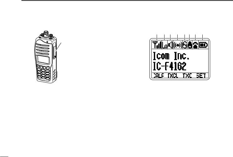
■ Function display
q w e r ty u i
 o
o
CALA


 TXCU
TXCU


 TXC
TXC


 SET
SET


 !0
!0
q SIGNAL STRENGTH INDICATOR
Indicates relative signal strength level.
w LOW POWER INDICATOR
Appears when low output power is selected. e AUDIBLE INDICATOR
Appears when the channel is in the ‘audible’ (unmute) condition.
Appears when the matched signal is received.
r COMPANDER INDICATOR
Appears when the compander function is activated.
t SCRAMBLER INDICATOR
Appears when the voice scrambler function is activated.
y BELL INDICATOR
Appears/blinks when the matched signal is received, according to the pre-programming.
u CALL CODE MEMORY INDICATOR
Appears when the call code memory is selected.
i BATTERY INDICATOR
Appears or blinks when the battery power decreases to a specified level.
Indication |
|
|
|
|
|
|
|
|
|
|
|
Battery level |
Full |
Middle |
Charging |
No battery |
|
required |
|||||
|
|
|
|
||
|
|
|
|
|


 blinks when the battery is over charged.

 blinks when the battery is exhausted.
o ALPHANUMERIC DISPLAY
Displays an operating channel number, channel name, Set mode contents, DTMF code, etc.
The indication mode can be selected from 1 line or 2 lines. Ask your dealer for details.
•In this instruction manual, the LCD illustration is described using the 2 lines indication mode.
!0KEY INDICATOR
Indicate the programmed function of the front panel keys ([P0], [P1], [P2] and [P3]).
PANEL DESCRIPTION 2
■ Programmable function keys
The following functions can be assigned to [EMR], [Side1], [Side2], [Side3], [P0], [P1], [P2] and [P3] programmable function keys.
Consult your Icom dealer or system operator for details concerning your transceivers programming.
If the programmable function names are bracketed in the following explanations, the specific key is used to activate the function depends on the programming.
CH UP AND DOWN KEYS “UP” “DOWN”
Push to select an operating channel. When [Rotary selector] selects “operating channel,” this key is not available.
Push to select a transmit code channel after pushing [TX Code CH Select].
Push to select a DTMF channel after pushing [DTMF Autodial].
Push to select a scan group after pushing and holding [Scan].
1
2
3
4
5
6
7
8
9
10
11
12
13
14
15
16

2 PANEL DESCRIPTION
ZONE KEY “ZONE”
Push this key, then push [CH Up] or [CH Down] to select the desired zone. When [Rotary selector] selects “operating zone,” this key operation is not available.
 What is “zone”?— Selected channels are assigned to a
zone according to how they are to be used in a group. For
 example, ‘Staff A’ and ‘Staff B’ are assigned into a “Busi-
  ness” zone, and ‘John’ and ‘Cindy’ are assigned into a “Pri-
  vate” zone.
ZONE UP AND DOWN KEYS “ZNUP” “ZNDN”
Push to select an operating zone. When [Rotary selector] selects “operating zone,” this key is not available.
SCAN KEY “SCAN”
Push to start and cancel scanning operation.
•When Power ON Scan function is activated, push to pause the scanning operation. And the paused scan resumes after the specified time period has passed.
Push and hold this key for 1 sec. to indicate the scan list, then push [CH Up] or [CH Down] to select the desired list.
SCAN ADD/DEL (TAG) KEY “SCAD”
Push to add or delete the selected channel to/from the scan group.
1.Push to indicate the scan group, then push [CH Up] or [CH Down] to select the desired group.
2.Push to add or delete the channel to/from the selected scan group.
3.Push and hold for 1 sec. to exit the scan group selection mode.
Push this key while scan is paused (a signal is detected) on a channel (except for priority channel,) the channel is cleared from the scan group.
 Depending on the setting, the cleared channel is added
  to the scan group again after the scan is cancelled.
  (Nuisance Delete function)
PRIORITY CHANNEL KEYS “PRA” “PRAR” “PRB” “PRBR”
Push to select Priority A or Priority B channel.
Push and hold [Prio A (Rewrite)] or [Prio B (Rewrite)] for 1 sec. to rewrite the Priority A or Priority B channel for the operating channel.
Loading...