


For Husqvarna Parts Call 606-678-9623 or 606-561-4983
Brush cutters, Trimmers,
Pruners, Hedge trimmers
Workshop Manual
101 90 19-26
www.mymowerparts.com

For Husqvarna Parts Call 606-678-9623 or 606-561-4983
Workshop Manual
Brush cutters, Trimmers,
Pruners, Hedge trimmers
Supplement for models 322, 325
List of Contents
1. Starter ___________________________________ 3
2. Ignition system ____________________________ 7
3. Fuel system _______________________________11
4. Centrifugal clutch _________________________ 19
5. Angle gear _______________________________ 23
6. Cylinder and piston _______________________ 27
7. Crankshaft and Crankcase _________________ 31
This supplement only takes up elements specific
to the above mentioned models.
For complete information when servicing we rec-
ommend that the supplement is studied together
with the Workshop Manual.
(Order. No. 101 89 22-01)
© Copyright Husqvarna AB, Sweden 1998
www.mymowerparts.com
1

For Husqvarna Parts Call 606-678-9623 or 606-561-4983
2
www.mymowerparts.com

For Husqvarna Parts Call 606-678-9623 or 606-561-4983
Starter
1.
Contents
Dismantling ________________________________ 4
Assembly _________________________________ 4
Replacing the drive pawls ____________________ 5
www.mymowerparts.com
3

For Husqvarna Parts Call 606-678-9623 or 606-561-4983
1
Starter
!
WARNING!
Protective glasses should be worn when working on the starter to avoid injury to the
eyes if, for some reason, the return spring should fly out.
Dismantling
Remove the 3 bolts and lift out the starter.
NOTE!
Ensure the bushes (A) that guide the starter against the fuel tank are not lost.
A
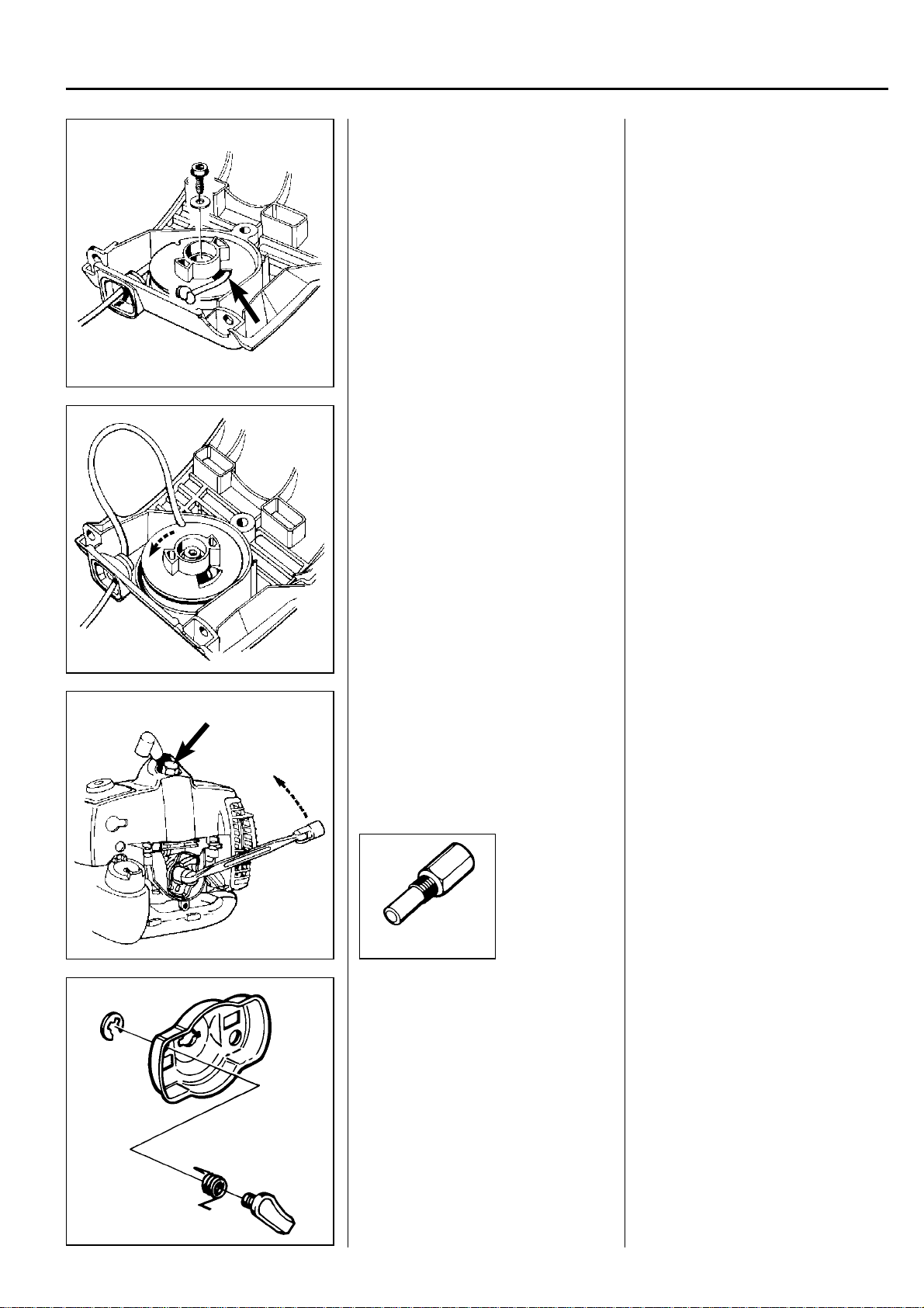
Off-load the spring pressure.
Remove the bolt from the centre of the
starter pulley and lift off the starter
pulley.
Assembly
Clean all component parts and assemble in the reverse order as stated for
dismantling.
Off-load the spring pressure as described in the Workshop Manual.
Remove the bolt from the centre of the
starter pulley. Carefully lift the starter
pulley out of the starter housing.
!
WARNING!
Use protective glasses. The return
spring is tensioned in the starter
pulley and can fly out and cause
personal injury with negligent
handling.
Assembly
Clean all component parts before
assembling.
Replace the return spring/starter pulley
and starter cord if necessary.
NOTE!
The return spring and the starter pulley
are supplied assembled and are fitted in
the starter housing as a single unit.
Exercise care when opening the
packaging so that the spring does not
fly out.
4
www.mymowerparts.com
For Husqvarna Parts Call 606-678-9623 or 606-561-4983
Starter
Fit the starter pulley.
Fit a new starter cord.
NOTE!
A new starter cord can be fitted without
the need of dismantling the starter!
Fit the starter handle.
Tension the return spring.
Check the spring tension.
Fit the starter on the engine body.
Do not forget the guide bushes for the
fuel tank.
1
Lubricate the axle spindle with a little
grease and fit the starter pulley.
Position the washer and tighten the
bolt.
Fit a new starter cord. Slide it into the
groove on the starter pulley as shown
in the diagram and out through the cord
guide in the starter housing.
Make sure the knot on the end of the
cord is as small as possible!
Fit the starter handle as described in
the Workshop Manual.
Tension the return spring. Pull out the
starter cord completely and lift it up
through the cut-out in the starter pulley.
Now turn the starter pulley 6 turns
anticlockwise
Check the spring tension. With the cord
fully extended it should be possible to
turn the starter pulley
half turn.
.
at least a further
Replacing the drive
pawls
Dismantle the drive cup.
504 91 06-05
Remove the circlip and replace the
drive pawl or spring if damaged.
Replacing the drive
pawls
Fit the piston stop, No. 504 91 06-05 in
the spark plug hole and loosen the nut
holding the drive cup.
Remove the circlip holding the drive
pawl.
Lift off the drive pawl and spring for
replacement.
Assemble in the reverse order as
stated for dismantling.
www.mymowerparts.com
5

For Husqvarna Parts Call 606-678-9623 or 606-561-4983
6
www.mymowerparts.com

For Husqvarna Parts Call 606-678-9623 or 606-561-4983
Ignition system
2.
Contents
Dismantling 8
Assembly 9
www.mymowerparts.com
7

For Husqvarna Parts Call 606-678-9623 or 606-561-4983
2
Ignition system
The engine is equipped with an electronic ignition
system with no moving parts. Consequently, a
faulty component cannot be repaired, but must be
replaced with a new component.
Dismantling
Dismantle the cylinder cover, the guard
over the muffler and the spark plug.
Unhook the throttle cable and remove
the bolts holding the clutch cover.
The ignition spark in an electronic ignition
system has a very short burn time and can
be judged to be weak and is at times difficult
to see when troubleshooting.
Dismantling
To gain access to the ignition system
the following components must be
dismantled:
Cylinder cover, guard over the muffler,
and the spark plug.
Unhook the throttle cable from the
carburettor.
Remove the clutch cover and loosen
the short-circuiting cable from the
ignition module.
504 90 00-02
B
A
B
Dismantle the ignition module and the
centrifugal clutch.
Remove the three bolts holding the
clutch cover.
Remove the complete clutch cover with
the shaft from the engine.
Loosen both the short-circuiting cable
lugs from the ignition module.
Remove the remaining bolts (A)
securing the ignition module as well as
the bolts (B) holding the centrifugal
clutch.
Lift off the clutch and ignition module.
504 90 00-03
8
www.mymowerparts.com

For Husqvarna Parts Call 606-678-9623 or 606-561-4983
Ignition system
Fit the piston stop No. 504 91 06-05
and remove the nut holding the
flywheel.
504 91 06-05
Dismantle the flywheel.
2
Fit the piston stop No. 504 91 06-05 in
the spark plug hole.
Make sure the piston stop is screwed
down to the bottom.
Remove the nut holding the flywheel.
Dismantle the flywheel from the
crankshaft using puller No. 502 51 49-01.
Gently hit the puller screw with a
hammer if the flywheel sits hard on the
crankshaft.
502 51 49-01
Assembly
Check that the key and keyway show
no signs of damaged.
Fit the centrifugal clutch.
NOTE!
Do not forget the washers between the
flywheel and the centrifugal clutch.
Fit the ignition module and adjust the
spark gap to 0.3 mm.
Assembly
Check that the cast key in the flywheel
and the keyway in the crankshaft are
not damaged.
If the crankshaft has two keyways, the
flywheel should be fitted to the righthand keyway seen from the end of the
shaft.
Fit the centrifugal clutch.
NOTE!
Do not forget the washers between the
flywheel and the centrifugal clutch.
Fit the ignition module.
To simplify the adjustment of the spark
gap, do not fit the short-circuiting cables
yet. This should be set to 0.3 mm
between the permanent magnets in the
flywheel and the ignition module.
Now fit the short-circuiting cables and
other components in the reverse order
as stated for dismantling.
502 51 34-02
www.mymowerparts.com
NOTE!
Do not forget the rubber bushes
between the clutch cover and fuel tank.
9
 Loading...