


 Loading...
GB
ES
DE
FR
Operator’s manual |
|
|
Please read the operator’s manual carefully and make sure |
|
|
you understand the instructions before using the machine. |
|
|
Manual de |
|
|
instrucciones |
|
|
Lea detenidamente el manual de instrucciones y asegúrese |
DMS 240 |
|
de entender su contenido antes de utilizar la máquina. |
||
|
||
Bedienungsanweisung |
|
|
Lesen Sie die Bedienungsanweisung sorgfältig durch und |
|
|
machen Sie sich mit dem Inhalt vertraut,bevor Sie das |
|
|
Gerät benutzen. |
|
|
Manuel d’utilisation |
GB ES DE FR |
|
|
Lire attentivement et bien assimiler le manuel d’utilisation avant d’utiliser la machine.
HUSQVARNA CONSTRUCTION PRODUCTS
KEY TO SYMBOLS
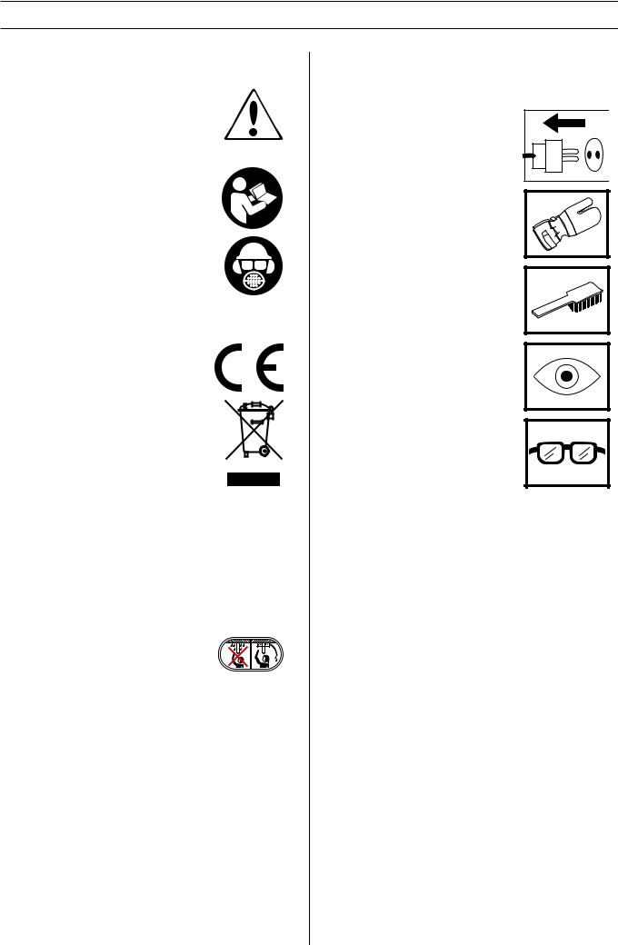
Symbols on the machine:
WARNING! The machine can be a dangerous tool if used incorrectly or carelessly, which can cause serious or fatal injury to the operator or others.
Please read the operator’s manual carefully and make sure you understand the instructions before using the machine.
Always wear:
• Approved protective helmet
• Approved hearing protection
•Protective goggles or a visor
•Breathing mask
This product is in accordance with applicable EC directives.
Environmental marking. Symbols on the product or its packaging indicate that this product cannot be handled as domestic waste. It must instead be submitted to an appropriate recycling station for the recovery of electrical and electronic equipment.
By ensuring that this product is taken care of correctly, you can help to counteract the
potential negative impact on the environment and people that can otherwise result through the incorrect waste management of this product.
For more detailed information about recycling this product, contact your municipality, your domestic waste service or the shop from where you purchased the product.
Ensure that water cannot leak into the machine when drilling in the ceiling. Use an appropriate water collector and cover the machine in plastic, but do not cover the air intakes and air outlets.
Other symbols/decals on the machine refer to special certification requirements for certain markets.
Symbols in the operator’s manual:
Inspection and/or maintenance should be carried out with the motor switched off and the plug disconnected.
Always wear approved protective gloves.
Regular cleaning is required.
Visual check.
Protective goggles or a visor must be worn.
2 – English

|
CONTENTS |
Contents |
|
KEY TO SYMBOLS |
|
Symbols on the machine: ............................................. |
2 |
Symbols in the operator’s manual: ............................... |
2 |
CONTENTS |
|
Contents ...................................................................... |
3 |
WHAT IS WHAT? |
|
What is what on the drilling machine? ......................... |
4 |
WHAT IS WHAT? |
|
What is what on the stand? ......................................... |
5 |
SAFETY INSTRUCTIONS |
|
Steps before using a new drilling machine .................. |
6 |
Personal protective equipment ..................................... |
6 |
Machine′s safety equipment ........................................ |
7 |
General safety precautions .......................................... |
8 |
PRESENTATION |
|
Drill motor and stand .................................................... |
10 |
Stand ........................................................................... |
10 |
Drill motor .................................................................... |
10 |
ASSEMBLY |
|
Fit the wheel kit ............................................................ |
11 |
Secure the stand .......................................................... |
11 |
Assembly of drill motor ................................................. |
12 |
Adjust the column tilt .................................................... |
12 |
STARTING AND STOPPING |
|
Before starting ............................................................. |
13 |
Starting ........................................................................ |
13 |
Stopping ....................................................................... |
13 |
MAINTENANCE |
|
Changing the drill bit .................................................... |
14 |
Maintenance of the drill motor ..................................... |
14 |
Stand maintenance ...................................................... |
15 |
Troubleshooting schedule ............................................ |
16 |
TECHNICAL DATA |
|
Drill motor .................................................................... |
17 |
Drill stand ..................................................................... |
17 |
EC-declaration of conformity ........................................ |
18 |
English – 3
WHAT IS WHAT?
1
2


 5 3
5 3 

8
4 |
6 |
|
7
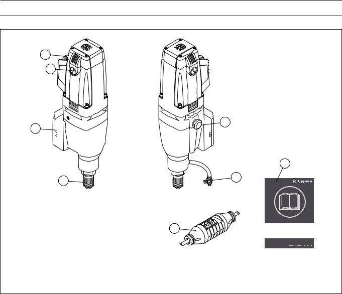
What is what on the drilling machine?
1 |
Switch |
5 |
Gear selector |
2 |
Carbon brush cover |
6 |
Water connector |
3 |
Fixing for stand |
7 |
Ground fault circuit interrupter (not for GB) |
4 |
Drill spindle |
8 |
Operator′s manual |
4 – English
WHAT IS WHAT?
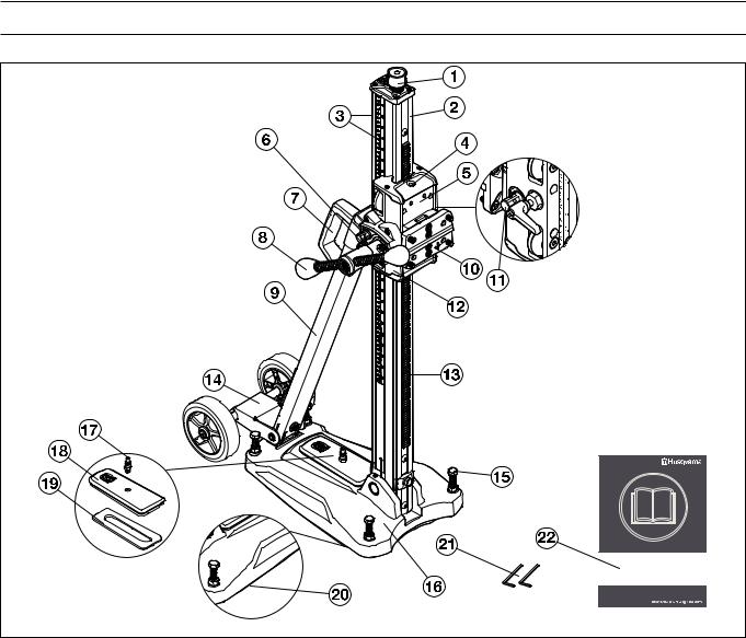
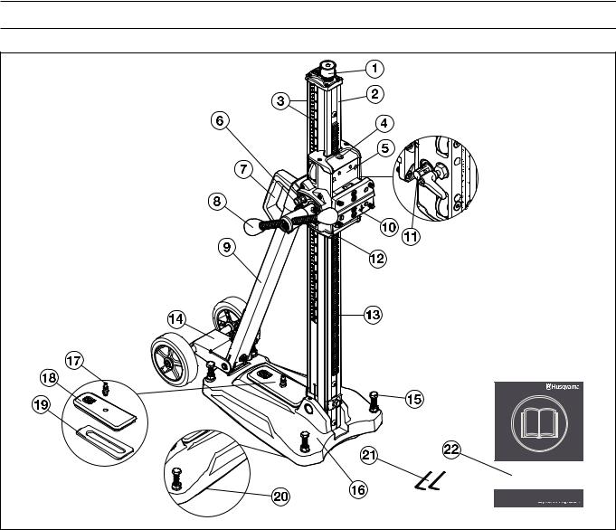
What is what on the stand?
1 |
Jacking screw |
12 |
Gear box |
2 |
Drill column |
13 |
Rack |
3 |
Depth and tilt scale |
14 |
Wheel set (removable) |
4 |
Vertical and horizontal level indicator |
15 |
Leveling adjustment screws |
5 |
Feeder housing |
16 |
Base plate with integrated vacuum function |
6 |
Locking screw, column tilt |
17 |
Quick coupling for vacuum pressure |
7 |
Carrying handle |
18 |
Vacuum cover |
8 |
Feed lever |
19 |
Gasket, vacuum cover |
9 |
Back support |
20 |
Gasket, base vacuum suction |
10 |
Quick mounting |
21 |
Allen key (3 mm, 4 mm) |
11 |
Feeder housing lock |
22 |
Operator′s manual |
English – 5
SAFETY INSTRUCTIONS
Steps before using a new drilling machine
•Do not use the drilling machine without first reading and understanding the contents of this Operator’s Manual.
•This machine is designed for and intended for drilling concrete, brick and different stone materials. All other use is improper.
•The machine is intended for use in industrial applications by experienced operators.
Always use common sense
It is not possible to cover every conceivable situation you can face when using a drilling machine. Always exercise care and use your common sense. Avoid all situations which you consider to be beyond your capability. If you still feel uncertain about operating procedures after reading these instructions, you should consult an expert before continuing. Do not hesitate to contact your dealer or us if you have any more questions about the use of the drilling machine. We will willingly be of service and provide you with advice as well as help you to use your drilling machine both efficiently and safely.
Do not hesitate to contact your dealer if you have any more questions about the use of the machine. We will willingly be of service and provide you with advice as well as help you to use your machine both efficiently and safely.
Let your Husqvarna dealer check the drilling machine regularly and make essential adjustments and repairs.
Husqvarna Construction Products has a policy of continuous product development. Husqvarna reserves the right to modify the design and appearance of products without prior notice and without further obligation introduce design modifications.
All information and all data in the Operator’s Manual were applicable at the time the Operator’s Manual was sent to print.
WARNING! Under no circumstances should
!you modify the original design of the machine without approval from the manufacturer. Always use original spare parts. Unauthorised modifications and/or accessories may lead to serious injury or death to the user or others.
WARNING! The use of products such as
!cutters, grinders, drills, that sand or form material can generate dust and vapours which may contain hazardous chemicals. Check the nature of the material you intend to process and use an appropriate breathing mask.
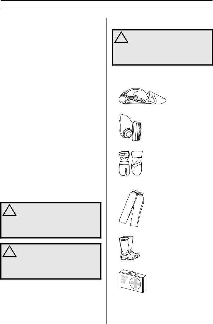
Personal protective equipment
! |
WARNING! You must use approved personal |
protective equipment whenever you use the |
|
machine. Personal protective equipment |
|
|
cannot eliminate the risk of injury but it will |
|
reduce the degree of injury if an accident |
|
does happen. Ask your dealer for help in |
|
choosing the right equipment. |
•Protective helmet
•Hearing protection
•Protective goggles or a visor
•Breathing mask
•Heavy-duty, firm grip gloves.
•Tight-fitting, heavy-duty and comfortable clothing that permits full freedom of movement.
•Boots with steel toe-caps and non-slip sole.
•Always have a first aid kit nearby.
6 – English
SAFETY INSTRUCTIONS
Machine′s safety equipment
This section describes the machine′s safety equipment, its purpose, and how checks and maintenance should be carried out to ensure that it operates correctly. See the ”What is what?” section to locate where this equipment is positioned on your machine.
! |
WARNING! Never use a machine that has |
faulty safety equipment! Carry out the |
|
inspection, maintenance and service |
|
|
routines listed in this section. |
All servicing and repair work on the machine requires special training. This is especially true of the machine′s safety equipment. If your machine fails any of the checks described below you must contact your service agent. When you buy any of our products we guarantee the availability of professional repairs and service. If the retailer who sells your machine is not a servicing dealer, ask him for the address of your nearest service agent.
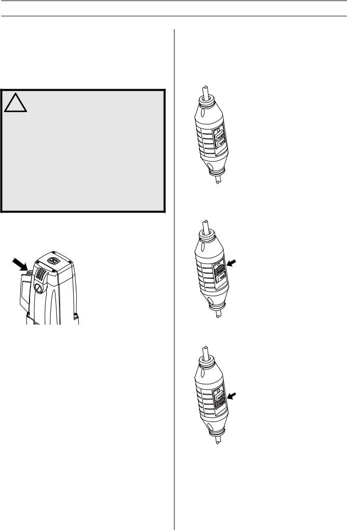
Switch
The power switch should be used to start and stop the machine.
Checking the power switch
•Start the machine by switching on the on-off switch.
•Switch the on-off switch off to stop the machine.
•A defective power switch should be replaced by an authorized service workshop.
Ground fault circuit interrupter
Ground fault circuit interrupters are for protection in case an electrical fault should occur.
The LED indicates that the ground fault circuit interrupter is on and that the machine can be switched on. If the LED is not on, push the RESET button (green).
Check the ground fault circuit interrupter
•Connect the machine to the socket. Push the RESET button (green) and the red LED lights up.
•Start the machine by pressing the power switch.
•Push the TEST button (blue).
•The ground fault circuit interrupter should trip and the machine switch off instantly. If not, contact your dealer.
•Reset with the RESET button (green).
English – 7

SAFETY INSTRUCTIONS
General safety precautions
! |
WARNING! Read all safety warnings and all |
instructions. Failure to follow the warnings |
|
and instructions may result in electrtic |
|
|
shock, fire and/or serious injury. |
Work area safety
•Keep work area clean and well lit. Cluttered or dark areas invite accidents.
•Do not operate power tools in explosive atmospheres, such as in the presence of flammable liquids, gases or dust. Power tools create sparks which may ignite the dust or fumes.
•People and animals can distract you causing you to lose control of the machine. For this reason, always remain concentrated and focused on the task.
•Do not use the machine in bad weather, such as dense fog, heavy rain, strong wind, intense cold, etc. Working in bad weather is tiring and can lead to dangerous conditions, e.g. slippery surfaces.
•Never start to work with the machine before the working area is clear and you have a firm foothold. Look out for any obstacles with unexpected movement. Ensure that no material can become loose and fall, causing injury when operating the machine.
•Always check the rear side of the surface where the drill bit will emerge when drilling right through. Secure and cordon off the area and make sure that no one can be injured or material damaged.
Electrical safety |
|
! |
WARNING! There is always a risk of shocks |
from electrically powered machines. Avoid |
|
unfavourable weather conditions and body |
|
|
contact with lightning conductors and metal |
|
objects. Always follow the instructions in the |
|
Operator’s manual to avoid damage. |
! |
WARNING! Do not wash the machine with |
water, as water can enter the electrical |
|
system or the engine and cause damage to |
|
|
the machine or short circuit. |
! |
WARNING! The machine (Great Britain 110 V) |
is not equipped with a ground fault circuit |
|
interrupter. The machine must always be |
|
|
used with an isolating transformer for |
|
protection in case an electrical fault should |
|
occur. |
•The machine should be connected to an earthed outlet socket.
•Check that the mains voltage corresponds with that stated on the rating plate on the machine.
•Check that the cord and extension cord are intact and in good condition. Use an extension cord intended for outdoor use.
•Never use the machine if the cord is damaged, hand it in to an authorized service workshop for repair.
•Do not use an extension cord while it is rolled up to avoid overheating.
•Never carry the machine by means of the cord and never pull out the plug by pulling the cord.
•Keep all cords and extension cords away from water, oil and sharp edges. Make sure the cord is not pinched in doors, fences or the like. Otherwise it can cause the object to become live.
•The power tool should not be exposed to more moisture than what is provided by the water system. Do not expose the power tool to rain. Water entering a power tool will increase the risk of electric shock.
•Ensure the cord is behind you when you start to use the machine so that the cord will not be damaged.
8 – English

SAFETY INSTRUCTIONS
Personal safety |
|
! |
WARNING! There is always a risk of crush |
injuries when working with products |
|
containing moving parts. Wear protective |
|
|
gloves to avoid body injuries. |
•Wear personal protective equipment. See instructions under the heading Personal protective equipment.
•Never use the machine if you are tired, if you have drunk alcohol, or if you are taking medication that could affect your vision, your judgement or your co-ordination.
•Prevent unintentional starting. Ensure the switch is in the OFF-position before connecting to power source. Carrying power tools with your finger on the switch or energising power tools that have the switch on invites accidents.
•Remove any adjusting key or wrench before turning the power tool on. A wrench or a key left attached to a rotating part of the power tool may result in personal injury.
•Never allow anyone else to use the machine without first ensuring that they have understood the contents of the operator’s manual.
•Be careful as clothing, long hair, and jewellery can get caught in moving parts.
•Remain at a distance from the drill bit when the motor is running.
•Make sure that no pipes or electrical cables are routed in the area to be drilled.
•Never leave the machine unsupervised with the motor running.
•Always unplug the machine during longer work breaks.
•Never work alone, always ensure there is another person close at hand. Apart from being able to receive help to assemble the machine, you can also get help if an accident should occur.
Use and care
•Never use a machine that is faulty. Carry out the checks, maintenance and service instructions described in this manual. Some maintenance and service measures must be carried out by trained and qualified specialists. See instructions under the heading Maintenance.
•Inspection and/or maintenance should be carried out with the motor switched off and the plug disconnected.
•Do not use the power tool if the switch does not turn it on and off. Any power tool that cannot be controlled with the switch is dangerous and must be repaired.
•Never use a machine that has been modified in any way from its original specification.
•Do not overload the machine. Overloading can damage the machine.
•Keep tools sharp and clean in order to enable safer work.
•Keep all parts in good working order and ensure that all fixtures are properly tightened.
Transport and storage
•Do not store or transport the drilling machine with the drill bit fitted in order to protect your drilling machine and drill bits from damage.
•Store the drilling machine in a lockable area so that it is out of reach of children and unauthorised persons.
•Store the drilling machine and stand in dry and frost free conditions.
English – 9
PRESENTATION
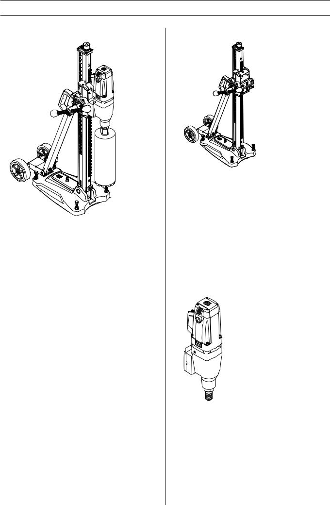
Drill motor and stand
It is our wish that you will be satisfied with your product and that it will be your companion for a long time. Think of this operator′s manual as a valuable document. By following its′ content (using, service, maintenance etc) the life span and the second-hand value of the machine can be extended. If you will sell this machine, make sure that the buyer will get the operator′s manual.
A purchase of one of our products gives you access to professional help with repairs and services. If the retailer who sells your machine is not one of our authorised dealers, ask him for the address of your nearest service workshop.
Husqvarna Construction Products has a policy of continuous product development. Husqvarna reserves the right to modify the design and appearance of products without prior notice and without further obligation introduce design modifications.
Stand
•The stand is for drilling in roofs, walls and floors.
•The drill stand is equipped with a quick connection plate for the drillmotor.
•The base plate is made of aluminium and is therefore very light weight. It has a integrated vacuum plate.
•The wheel kit is dismountable.
•The column can be tilted 0-60°.
•The feeder housing’s transmission is adjustable. The higher gives 2.5:1 and the lower, 1:1.
•Feed lever can be used to adjust base plate leveling screws and set desired column tilt.
Drill motor
•DMS 240 is an electric drill, intended for drilling concrete, brick and various stone materials.
•The drilling machine has a modular design and is easy to assemble.
•The machine is intended for stand mounted drilling.
•The machine is equipped with two gears.
•The machine is double insulated.
•The overload protection disconnects the power, if the machine is subjected to heavy loads or if the drill bit jams.
•The machine is water cooled.
10 – English
ASSEMBLY
Fit the wheel kit
Fit the wheel set in the mount on the backside of the bottom plate and tighten the screws.
Secure the stand
There are three methods for fixing the stand.
•Securing with vacuum plate
•Fixing with expander or anchor
•Fixing with threaded rod, washer and lock nut
Securing with vacuum plate
! |
WARNING! The vacuum plate must never be |
used for ceiling or wall drilling. Careless or |
|
incorrect use can result in serious, even |
|
|
fatal injury. |
If the vacuum plate is used, make sure the support surface is not porous and can loosen from the floor or the wall. Make sure that the vacuum pump has sufficient power to secure the vacuum plate.
•Connect the vacuum pump to the quick coupling for vacuum pressure on the base plate.
•Place the bottom plate in the desired position.
•Switch on the vacuum pump. A minimum pressure of 635 mm Hg (25 inch Hg) must be reached so that the base plate seals tightly against the surface.
Fixing with expander or anchor
IMPORTANT! When drilling roofs, only expander or anchor suitable for surfaces exposed to tensile forces should be used.
Use only expander or anchor which is approved for current application.
335 mm (13,2”)
•Drill a hole for the expander/anchor at a distance of 335 mm (13.2”) from the centre of the hole.
•Bolt down the base plate.
Check carefully that the expander is secured correctly.
•The bottom plate can be adjusted to the surface by using the leveling adjustment screws. Use the feed lever.
Fixing with threaded rod, washer and lock nut
If the mounting surface is inadequate for drilling in roofs or walls, the base plate can be fixed using a threaded rod, which is mounted on the backside with a washer and lock nut.
Drilling in the ceiling
! |
WARNING! Use a water collector to avoid |
water penetrating into the machine. The |
|
machine must be covered with plastic or the |
|
|
like in order to prevent water penetrating |
|
into the machine, but do not cover the air |
|
intakes and air outlets. |
English – 11
ASSEMBLY
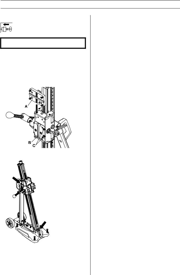
Assembly of drill motor
IMPORTANT! Always pull out the plug from the outlet socket before cleaning, maintenance or assembly.
•Always remove the drill bit before the motor is mounted or dismounted.
•Lock the feed housing lock.
•Fit the drill motor on the quick mount (A).
•Mount the quick mounting and drilling machine in the track on the locking clamp.
•Secure with the locking screws (C).
Adjust the column tilt
Loosen the locking screws for column tilt and set the desired drill angle. Tighten the locking screws. Use the feed lever. The column can be tilted 0-60°.
The angle indicator can be used for approximate adjustment. If higher precision is required, alternative measuring methods should be used.
12 – English
STARTING AND STOPPING
Before starting
WARNING! Note the following before ! starting:
The machine should be connected to an earthed outlet socket.
Check that the mains voltage corresponds with that stated on the rating plate on the machine. Keep people and animals well away from the working area.
WARNING! Before drilling, check that all
!locking screws are tightened well.
Serious accidents can occur if the concrete core remains in the drill when backing out the drill motor/drill from the floor, wall or ceiling.
•Prevent unintentional starting. Ensure the switch is in the OFF-position before connecting to power source and/or battery pack, picking up or carrying the tool. Carrying power tools with your finger on the switch or energising power tools that have the switch on invites accidents.
•Remove any adjusting key or wrench before turning the power tool on. A wrench or a key left attached to a rotating part of the power tool may result in personal injury.
Make sure that:
•The switch is undamaged. If not, the switch must be replaced by an authorised repairman.
•The machine and its equipment are correctly installed:
-The drill is secured properly.
-The stand is firmly attached.
-Secure the machine on the stand using a suitable method.
•Wear personal protective equipment. See instructions under the heading Personal protective equipment.
•Water cooling is connected to the machine.
Ground fault circuit interrupter
Make sure the ground fault circuit interrupter is switched on. The LED indicates that the ground fault circuit interrupter is on and that the machine can be switched on. If the LED is not on, push the RESET button (green).
Check the ground fault circuit interrupter. See instructions under the heading Checking, maintaining and servicing the machine’s safety equipment.
Drilling in the ceiling |
||
! |
WARNING! The vacuum plate must never be |
|
used for ceiling drilling. |
||
|
||
Use a water collector to avoid water penetrating into the machine. The machine must be covered with plastic or the like in order to prevent water penetrating into the machine, but do not cover the air intakes and air outlets.
! |
WARNING! Check that no one on the floor |
below can be injured by falling concrete |
|
cores. |
Starting
•Turn on the water cooling.
•Press in the switch fully.
•Allow the machine to come up to full speed before contacting workpiece.
•Start to feed the drill bit with the help of the feed handle.
Use very light pressure for the first few millimeters to keep the bit from wandering. Then proceed normally. It’s not necessary to use excessive force. This will only slow drilling and overload the motor.
Use especially light pressure when you encounter steel reinforcing rods. High pressure against reinforcing rods will trip the circuit breaker. If the circuit breaker trips, remove the bt from contact with the workpiece before resetting.
Stopping
! |
WARNING! The drill bit continues to rotate |
for a while after the motor has been switched |
|
off. Do not stop the drill bit with your hands. |
|
|
Personal injuries can occur. |
Shut down the machine by pressing the power switch.
Cooling
Run the machine unloaded for a minute or two to cool the motor.
This will also blow dust and dirt out of the motor, ensuring longer life for the machine.
English – 13
MAINTENANCE
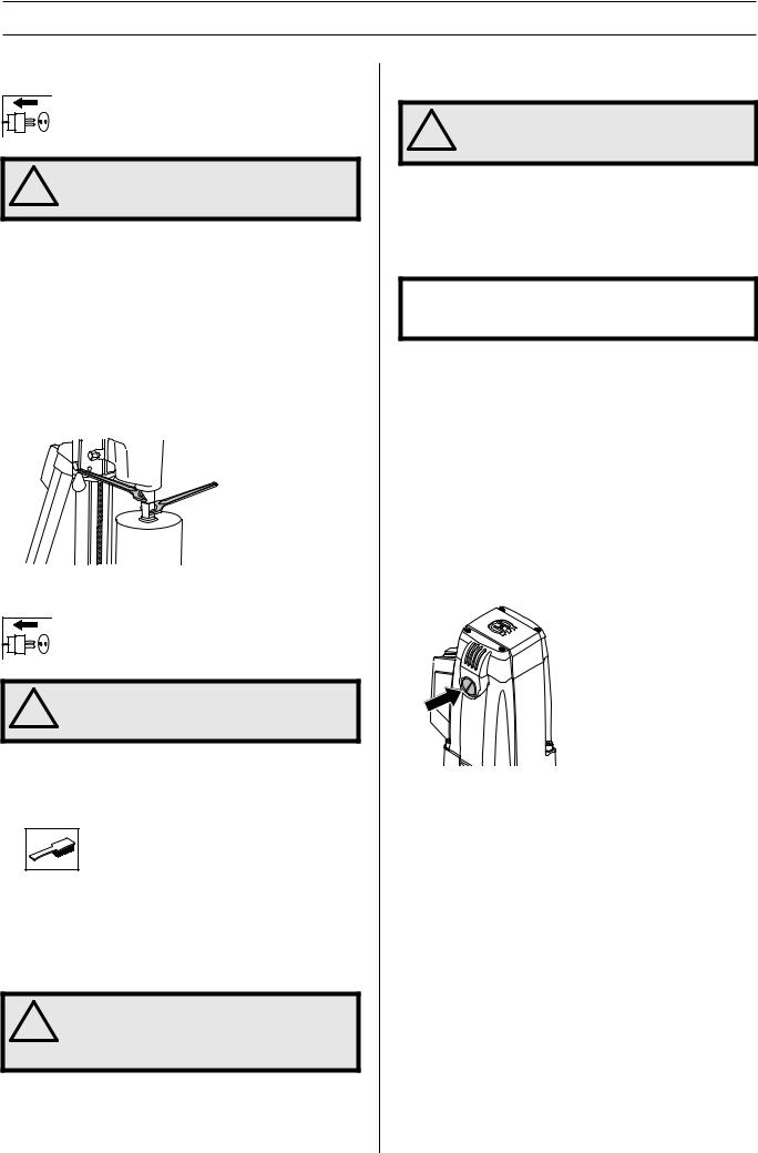
Changing the drill bit
! |
WARNING! Always pull out the plug from the |
outlet socket before cleaning, maintenance |
|
or assembly. |
1Pull out the plug.
2Get:
-The new drill bit.
-Open-ended spanners.
-Water-resistant grease.
3Remove the old drill bit using the open-ended spanners.
4Apply water-resistant grease to the thread of the new drill bit.
5Attach the drill bit using the open-ended spanners.
Maintenance of the drill motor
WARNING! Inspection and/or maintenance
!should be carried out with the motor switched off and the plug disconnected.
The lifetime of your machine can be extended considerably if it is used, cared for and maintained in the proper manner.
Cleaning
•Keep the machine and drill bit clean in order for drilling to be carried out safely.
•In order for the machine to always be cooled sufficiently the cooling air openings must be kept clear and clean. Blow down the machine regularly with compressed air.
WARNING! Do not wash the machine with
!water, as water can enter the electrical system or the engine and cause damage to the machine or short circuit.
Electrical Feed |
|
! |
WARNING! Never use damaged cables. They |
can cause serious, even fatal, personal |
|
injuries. |
|
Check that the cord and extension cord are intact and in good condition. Never use the machine if the cord is damaged, hand it in to an authorized service workshop for repair.
Repairs
IMPORTANT! All types of repairs may only be carried out by authorised repairmen. This is so that the operators are not exposed to great risks.
Clutch disc
If transmitted torque is lowered, clutch disc requires adjustments. Entrust this to an authorized service center.
Replacing the carbon brushes
The carbon brushes must be removed and checked regularly. Weekly if the machine is used daily or at longer intervals if the machine is used more seldom. The area of wear should be even and undamaged.
Both carbon brushes must always be replaced as a pair, but one at a time. Do as follows:
1Remove the cover for the carbon brushes using a flat wide screwdriver.
2Carefully remove the carbon brushes. The carbon brushes must be replaced if there is less than 6 mm remaining on the brushes.
3Fit new carbon brushes.
4Screw on the brush cover.
5Let the machine idle for 10 minutes to run in the new carbon brushes.
Daily maintenance
1Check that nuts and screws are tight.
2Check that the power switch unit works smoothly.
3Clean the outside of the machine.
4Check and clean the cooling air openings.
5Check that the cord and extension cord are intact and in good condition.
14 – English

MAINTENANCE
Stand maintenance
! |
WARNING! Inspection and/or maintenance |
should be carried out with the motor |
|
switched off and the plug disconnected. |
Cleaning and lubrication
IMPORTANT! Remove the drill motor. For maintenance of the drill motor see maintenance of the drill motor.
•It is important that the drill stand is kept clean for functionality to be maintained.
•Clean the stand using a high pressure washer and then wipe dry.
•Lubricate the moving parts on the stand. Apply grease to counteract corrosion on the contact surfaces.
Adjusting the feed housing
If there is play between the column and the feed housing, the play must be adjusted.
•Remove top and bottom plastic carriage covers.
•Loosen set screws holding guide roller shafts.
•Start with the top guide roller. Use a flat screwdriver and turn clockwise to guide the roller closer to the column.
Tighten set screw to lock the guide roller shaft.
•Adjust the lower roller by screwing anti-clockwise to guide the roller nearer to the column.
•Tighten set screw to lock the guide roller shaft.
•Use the feed lever to see if the feed housing moves smoothly on the column. If not, adjust the rollers again.
•Fit the top and bottom plastic carraiage covers.
Repairs
IMPORTANT! All types of repairs may only be carried out by authorised repairmen. This is so that the operators are not exposed to great risks.
Daily maintenance
1Check that nuts and screws are tight.
2Clean the outside of the machine.
3Check that the feed crank can be moved without resistance.
4Check that the gearing moves easily and does not cause any noise.
5Check for any wear or damage on the column.
6Check that the feed housing can be moved easily and does not backlash against the stand column.
English – 15

MAINTENANCE
Troubleshooting schedule
Problem |
Steps on the spot |
Probable cause |
Solution |
|
|
|
|
|
|
Bit is worn out. |
Replace bit. |
|
|
|
|
|
|
Bit is clogged with chips. |
Clean bit with a wire brush and |
|
Check bit. |
increase water pressure. |
|
|
|
||
Drilling is unusually |
|
|
|
|
Diamond is rounded. |
Use a softer bond bit. Increase |
|
slow. |
|
force on handle. |
|
|
|
||
|
|
|
|
|
Check for metal |
|
Ease up the handle to avoid |
|
powder in waste |
Drill is cutting reinforcing rods. |
|
|
tripping the circuit breaker. |
||
|
water. |
|
|
|
|
|
|
|
|
|
|
|
|
|
Using a wrench, rotate the bit |
|
|
Stone or steel bar is caught |
clockwise to free it while backing |
|
|
out the handle. (Rotating it |
|
|
|
between core and bit. |
|
|
|
counterclockwise may unscrew |
|
|
|
|
|
|
|
|
the bit from the tube.) |
|
|
|
|
Bit is stuck. |
Shut off drill. |
Base wanders during drilling. |
Reset the base and tighten |
|
|
securely. |
|
|
|
|
|
|
|
|
|
|
|
Clamp has too much free play. |
Adjust clearance of clamp |
|
|
properly. |
|
|
|
|
|
|
|
|
|
|
|
The bit’s outer diameter is the |
Replace bit. |
|
|
same as the tube’s. |
|
|
|
|
|
|
|
|
|
|
|
Clamp has too much free play. |
Adjust clearance of clamp |
|
|
properly. |
|
|
|
|
|
|
|
|
|
Tube is abraded. |
|
Bit, tube, or base are loose. |
Tighten securely. |
|
|
|
|
|
Bit is deformed. |
Replace bit. |
|
|
|
||
|
|
|
|
|
|
Chips not discharging well. |
Increase water pressure and |
|
|
volume. |
|
|
|
|
|
|
|
|
|
16 – English

TECHNICAL DATA
Drill motor
Electric motor
Rated voltage, V
Rated output, W
Rated current, A
230 V
100-120 V
Weight, kg/lbs
Spindle speed, idle, rpm
Position 1
Position 2
Drill bit
Max. drill diameter, mm/inches
Spindle thread, inner
Spindle thread, outer
Water connector
Noise emissions (see note 1)
Sound power level, measured dB(A)
Sound power level, guaranteed LWA dB(A)
Sound levels (see note 2)
Sound pressure level at the operators ear, dB(A)
Vibration levels (see note 3)
Handle, m/s2
Single-phase 230/100-120 2400
10A
20A
5,9/13
390
890
250/10
G 1/2” outer 5/8” 11 UNC 1 1/4” 7 UNC
G 1/4”
106
107
90
<2,5
Note 1: Noise emissions in the environment measured as sound power (LWA) in conformity with EN 12348.
Note 2: Noise pressure level according to EN 12348. Reported data for noise pressure level has a typical statistical dispersion (standard deviation) of 1.0 dB(A).
Note 3: Vibration level according to EN 12348. Reported data for vibration level has a typical statistical dispersion (standard deviation) of 1 m/s2.
Drill stand
Height, mm/inches |
1052/41,4 |
Width, mm/inches |
266/10,5 |
Depth, mm/inches |
545/21,5 |
Weight, kg/lbs |
14,5/32 |
Travel length, mm/inch |
686/27 |
The column's angling |
0-60° |
English – 17

TECHNICAL DATA
EC-declaration of conformity
(Applies to Europe only)
Husqvarna AB, SE-433 81 Göteborg, Sweden, tel: +46-31-949000, declares under sole responsibility that drilling machine and stand Husqvarna DMS 240 from 2010’s serial number and onward (the year is stated in plain text on the type plate plus a subsequent serial number) conform with the regulations in the COUNCIL’S DIRECTIVE:
•of May 17, 2006 "relating to machinery" 2006/42/EC
•of December 15, 2004 ”relating to electromagnetic compatibility” 2004/108/EC.
•of December 12, 2006 ”relating to electrical equipment” 2006/95/EC.
The following standards have been applied: EN ISO 12100:2003, EN 55014-1:2006, EN 55014-2/A1:2001, EN 61000-3-2:2006, EN 61000-3-3/A1/A2:2005, EN 12348/A1:2009.
Göteborg December 29, 2009
Henric Andersson
Vice President, Head of Power Cutters and Construction Equipment
Husqvarna AB
(Authorized representative for Husqvarna AB and responsible for technical documentation.)
18 – English
ACLARACIÓN DE LOS SÍMBOLOS
Símbolos en la máquina:
¡ATENCIÓN! La máquina, si se utiliza de forma errónea o descuidada, puede ser una herramienta peligrosa que puede causar daños graves e incluso la muerte al usuario y a otras personas.
Lea detenidamente el manual de instrucciones y asegúrese de entender su contenido antes de utilizar la máquina.
Utilice siempre:
• Casco protector homologado
• Protectores auriculares homologados
•Gafas protectoras o visor
•Máscara respiratoria
Este producto cumple con la directiva CE vigente.
Etiquetado ecológico. El símbolo en el producto o en su envase indica que no se puede tratar este producto como desperdicio doméstico. Deberá por lo tanto depositarse en un centro de recogida adecuado para el reciclado de equipos eléctricos y electrónicos.
Haciendo que este producto sea manipulado adecuadamente, se ayuda a evitar consecuencias negativas potenciales para el medio ambiente y las personas, lo que puede ocurrir con la manipulación inadecuada como residuos del producto.
Para obtener información más detallada sobre el reciclado de este producto, contacte con la oficina municipal local, con el servicio de eliminación de desperdicios domésticos o con la tienda donde compró el producto.
Al perforar en techo, comprobar que no puede entrar agua en la máquina. Utilizar un colector de agua adecuado y cubrir la máquina con un plástico, pero sin tapar las bocas de entrada y salida de aire.
Los demás símbolos/etiquetas que aparecen en la máquina corresponden a requisitos de homologación específicos en determinados mercados.
Símbolos en el manual de instrucciones:
El control y/o mantenimiento de la máquina debe hacerse con el motor parado y el enchufe desenchufado.
Utilice siempre guantes protectores homologados.
La máquina debe limpiarse regularmente.
Control visual.
Debe utilizarse gafas protectoras o visor.
Spanish – 19

|
ÍNDICE |
Índice |
|
ACLARACIÓN DE LOS SÍMBOLOS |
|
Símbolos en la máquina: ............................................. |
19 |
Símbolos en el manual de instrucciones: .................... |
19 |
ÍNDICE |
|
Índice ........................................................................... |
20 |
¿QUÉ ES QUÉ? |
|
Componentes de la taladradora ................................... |
21 |
¿QUÉ ES QUÉ? |
|
Componentes del soporte ............................................ |
22 |
INSTRUCCIONES DE SEGURIDAD |
|
Medidas a tomar antes de utilizar una taladradora |
|
nueva ........................................................................... |
23 |
Equipo de protección personal .................................... |
23 |
Equipo de seguridad de la máquina ............................ |
24 |
Instrucciones generales de seguridad ......................... |
25 |
PRESENTACIÓN |
|
Motor de taladradora y soporte .................................... |
27 |
Soporte ........................................................................ |
27 |
Motor de taladradora .................................................... |
27 |
MONTAJE |
|
Instalación del conjunto del eje con ruedas ................. |
28 |
Sujeción de la base ..................................................... |
28 |
Montaje del motor de la perforadora ............................ |
29 |
Ajuste de la inclinación de la columna ......................... |
29 |
ARRANQUE Y PARADA |
|
Antes de arrancar ........................................................ |
30 |
Arranque ...................................................................... |
30 |
Parada ......................................................................... |
30 |
MANTENIMIENTO |
|
Cambio de broca ......................................................... |
31 |
Mantenimiento del motor de taladradora ..................... |
31 |
Mantenimiento del soporte .......................................... |
32 |
Tabla de localización de fallos ...................................... |
33 |
DATOS TECNICOS |
|
Motor de taladradora .................................................... |
34 |
Base del taladro ........................................................... |
34 |
Declaración CE de conformidad .................................. |
35 |
20 – Spanish
¿QUÉ ES QUÉ?
1
2


 5 3
5 3 

8
4 |
6 |
|
7
Componentes de la taladradora
1 |
Interruptor |
5 |
Selector de velocidad |
2 |
Tapa de escobillas |
6 |
Conexión de agua |
3 |
Sujeción para la base |
7 |
Interruptor de circuito de pérdida a tierra |
4 |
Husillo de taladradora |
8 |
Manual de instrucciones |
Spanish – 21
¿QUÉ ES QUÉ? |
Componentes del soporte
1 |
Tornillo de compresión |
12 |
Caja de engranajes |
2 |
Columna de perforación |
13 |
Cremallera |
3 |
Profundidad y escala de inclinación |
14 |
Conjunto de eje con ruedas (extraíble) |
4 |
Indicador de nivel vertical y horizontal |
15 |
Tornillos de ajuste |
5 |
Caja de alimentación |
16 |
Placa base con función de vacío integrada |
6 |
Tornillo de fijación, columna de perforación inclinada |
17 |
Acoplamiento rápido para presión de vacío |
7 |
Mango de transporte |
18 |
Cubierta de vacío |
8 |
Palanca de alimentación |
19 |
Junta, cubierta de vacío |
9 |
Soporte en ángulo |
20 |
Junta, succión de vacío |
10 |
Montaje rápido |
21 |
Llave Allen (3 mm, 4 mm) |
11 |
Bloqueo de la caja de alimentación |
22 |
Manual de instrucciones |
22 – Spanish
Loading...