


 Loading...
GB
ES
DE
FR
Operator’s manual
Please read the operator’s manual carefully and make sure you understand the instructions before using the machine.
Manual de instrucciones
Lea detenidamente el manual de instrucciones y asegúrese de entender su contenido antes de utilizar la máquina.
Bedienungsanweisung
Lesen Sie die Bedienungsanweisung sorgfältig durch und machen Sie sich mit dem Inhalt vertraut,bevor Sie das Gerät benutzen.
Manuel d’utilisation
Lire attentivement et bien assimiler le manuel d’utilisation avant d’utiliser la machine.
DMS 160
A/AT/Gyro
GB ES DE FR
HUSQVARNA CONSTRUCTION PRODUCTS
KEY TO SYMBOLS
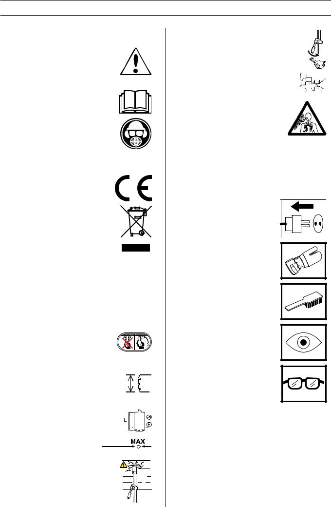
Symbols on the machine:
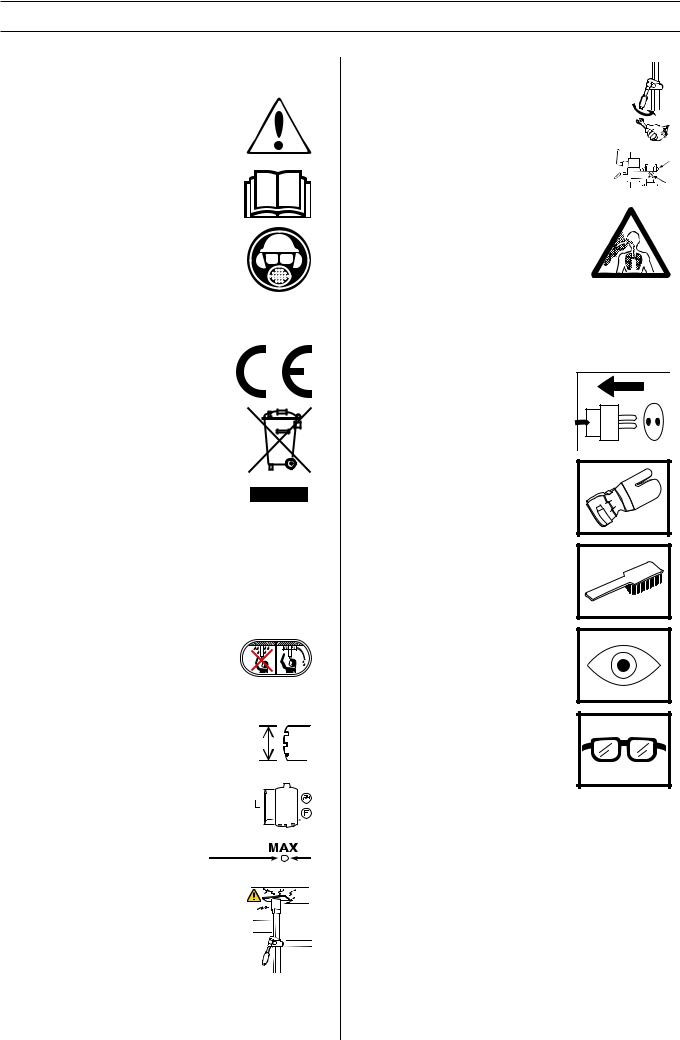
WARNING! The machine can be a dangerous tool if used incorrectly or carelessly, which can cause serious or fatal injury to the operator or others.
Please read the operator’s manual carefully and make sure you understand the instructions before using the machine.
Always wear:
• Approved protective helmet
• Approved hearing protection
•Protective goggles or a visor
•Breathing mask
This product is in accordance with applicable EC directives.
Environmental marking. Symbols on the product or its packaging indicate that this product cannot be handled as domestic waste. It must instead be submitted to an appropriate recycling station for the recovery of electrical and electronic equipment.
By ensuring that this product is taken care of correctly, you can help to counteract the
potential negative impact on the environment and people that can otherwise result through the incorrect waste management of this product.
For more detailed information about recycling this product, contact your municipality, your domestic waste service or the shop from where you purchased the product.
Ensure that water cannot leak into the machine when drilling in the ceiling. Use an appropriate water collector and cover the machine in plastic, but do not cover the air intakes and air outlets.
The drilling machine must be suitable and designed for the size of drill bit.The max drill bit diameter is stated on the machine.
Use a drill suitable for the work.
Ø
Load/power indication (LCS-Load control system).
Check that the ceiling is strong enough. The ceiling should be solid.
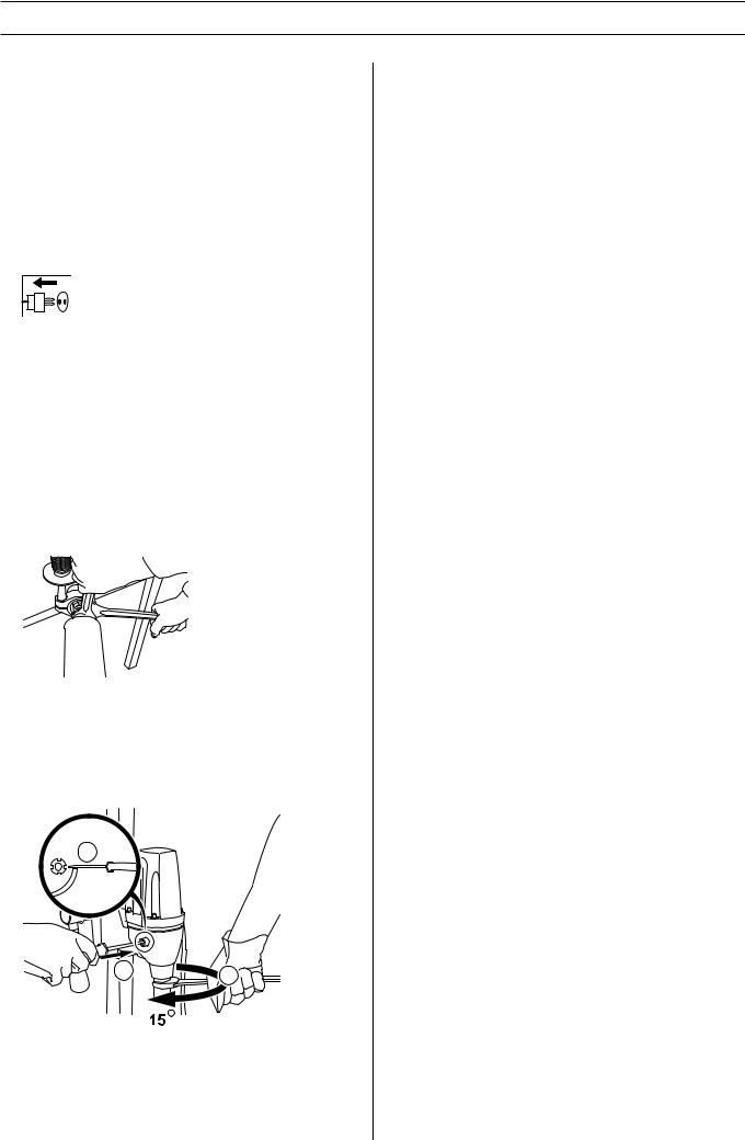
Make sure that the fork grips in the inner ear. Tighten using a suitable spanner.
Lock the nut using a 30 mm spanner. Check the lock nut on the L-handle. Make sure that it is tightened.
WARNING! Dust forms when drilling, which can cause injuries if inhaled. Use an approved breathing mask. Always provide for good ventilation.
Other symbols/decals on the machine refer to special certification requirements for certain markets.
Symbols in the operator’s manual:
Inspection and/or maintenance should be carried out with the motor switched off and the plug disconnected.
Always wear approved protective gloves.
Regular cleaning is required.
Visual check.
Protective goggles or a visor must be worn.
2 – English

CONTENTS
Contents |
|
KEY TO SYMBOLS |
|
Symbols on the machine: ............................................. |
2 |
Symbols in the operator’s manual: ............................... |
2 |
CONTENTS |
|
Contents ...................................................................... |
3 |
WHAT IS WHAT? |
|
What is what on the drilling machine? ......................... |
4 |
WHAT IS WHAT? |
|
What is what on the stand? ......................................... |
5 |
SAFETY INSTRUCTIONS |
|
Steps before using a new drilling machine .................. |
6 |
Personal protective equipment ..................................... |
6 |
Machine′s safety equipment ........................................ |
7 |
Checking, maintaining and servicing the machine′s |
|
safety equipment .......................................................... |
7 |
General safety precautions .......................................... |
7 |
PRESENTATION |
|
Drill motor and stand .................................................... |
8 |
Drill motor DMS160 ..................................................... |
8 |
Stand DMS160 ........................................................... |
8 |
ASSEMBLY |
|
Assembling the stand - DMS160 A/AT ......................... |
9 |
Assembling the stand - DMS160 Gyro ......................... |
9 |
STARTING AND STOPPING |
|
Before starting ............................................................. |
12 |
Starting ........................................................................ |
12 |
Stopping ....................................................................... |
12 |
WORKING TECHNIQUES |
|
General working instructions ....................................... |
13 |
Using the machine ....................................................... |
14 |
MAINTENANCE |
|
Maintenance of the drill motor ..................................... |
15 |
Stand maintenance ...................................................... |
16 |
TECHNICAL DATA |
|
Drill motor DMS160 ..................................................... |
17 |
Stand DMS160 ........................................................... |
18 |
EC-declaration of conformity ........................................ |
18 |
English – 3
WHAT IS WHAT?
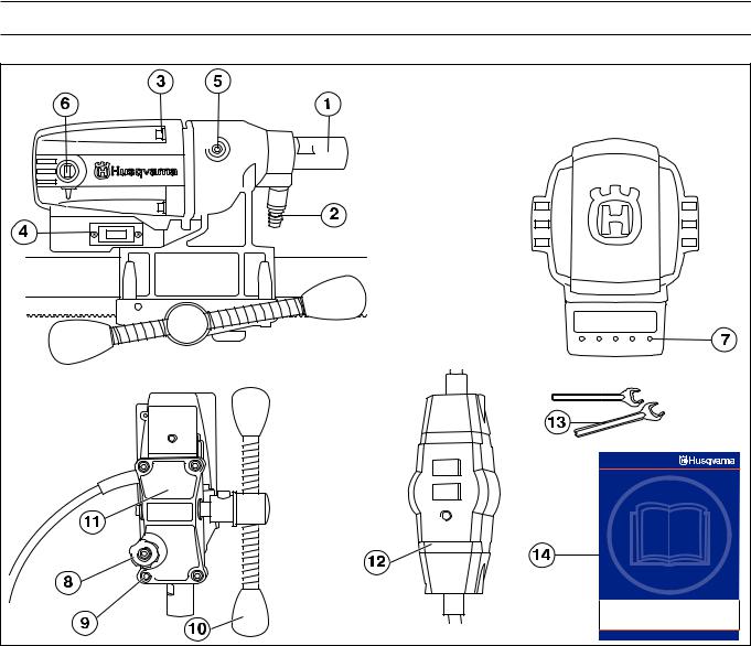
What is what on the drilling machine?
1 |
Drill spindle |
8 |
Locking knob |
2 |
Water connector |
9 |
Screws (4) for feeder rear section and gearbox |
3 |
Screws holding together the gearbox and the motor. |
10 |
Feeder handle |
4 |
Switch |
11 |
Feeder rear section |
5 |
Cover for slip clutch (SMC) |
12 |
PRCD Earth-fault breaker |
6 |
Carbon brush cover |
13 |
Spanners |
7 |
Load/power indication (LCS-Load control system). |
14 |
Operator′s manual |
4 – English
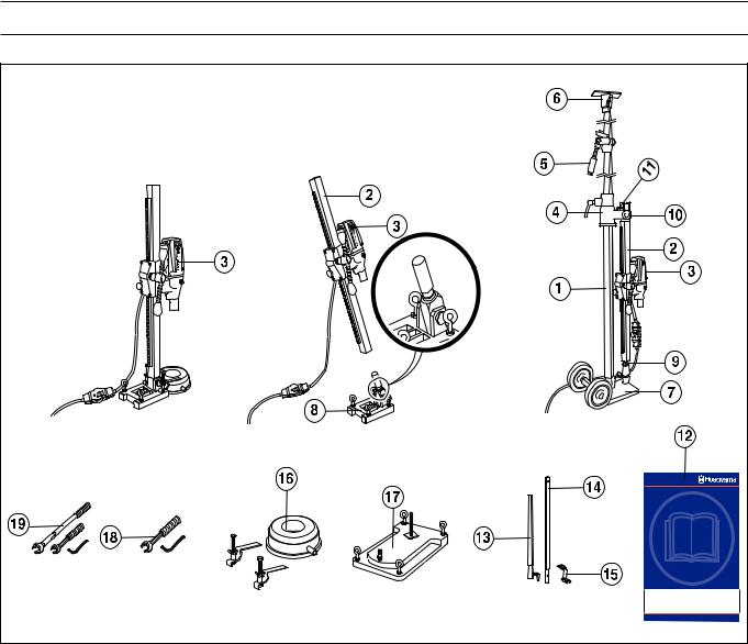
WHAT IS WHAT?
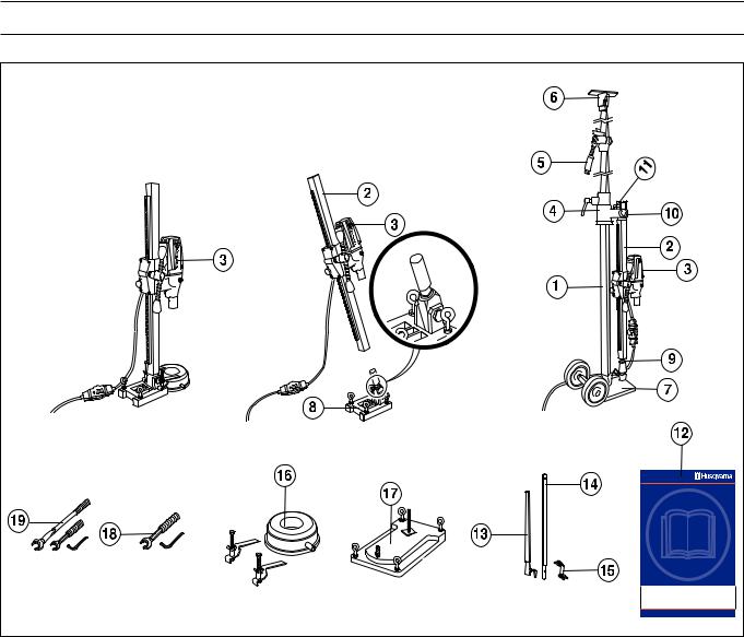
What is what on the stand?
1 |
Telescopic support column 40 |
11 |
L-handle |
2 |
Drill column |
12 |
Operator′s manual |
3 |
Drill motor DMS160 |
13 |
Extension module U (Available as an accessory.) |
4 |
Wall rail |
14 |
Extension module l (Available as an accessory.) |
5 |
Support column/locking mechanism |
15 |
Expansion attachment (Available as an accessory.) |
6 |
Ceiling plate |
16 |
Water collector (Available as an accessory.) |
7 |
Base plate (GB 40 T) with transport wheels |
17 |
Vacuum plate (Available as an accessory.) |
8 |
Expander angle base plate |
18 |
Tool kit DMS160 AT |
9 |
Column screw and lock screw |
19 |
Tool kit DMS160 Gyro |
10 |
Locking nut |
|
|
English – 5
SAFETY INSTRUCTIONS
Steps before using a new drilling machine
•Read through the operating instructions carefully before you begin using the machine.
•This machine is designed for and intended for drilling concrete, brick and different stone materials. All other use is improper.
•The machine is intended for use in industrial applications by experienced operators.
•Check the assembly of the drill, see the section changing the drill bit.
•Check that the cord and extension cord are intact and in good condition.
•Keep the workplace tidy. Disorder leads to accident risks.
Always use common sense
It is not possible to cover every conceivable situation you can face when using a drilling machine. Always exercise care and use your common sense. Avoid all situations which you consider to be beyond your capability. If you still feel uncertain about operating procedures after reading these instructions, you should consult an expert before continuing. Do not hesitate to contact your dealer or us if you have any more questions about the use of the drilling machine. We will willingly be of service and provide you with advice as well as help you to use your drilling machine both efficiently and safely.
Let your Husqvarna dealer check the drilling machine regularly and make essential adjustments and repairs.
All information and all data in the Operator’s Manual were applicable at the time the Operator’s Manual was sent to print.
! |
WARNING! Under no circumstances may the |
design of the machine be modified without |
|
the permission of the manufacturer. Always |
|
|
use genuine accessories. Non-authorized |
|
modifications and/or accessories can result |
|
in serious personal injury or the death of the |
|
operator or others. |
WARNING! The use of products such as
!cutters, grinders, drills, that sand or form material can generate dust and vapours which may contain hazardous chemicals. Check the nature of the material you intend to process and use an appropriate breathing mask.
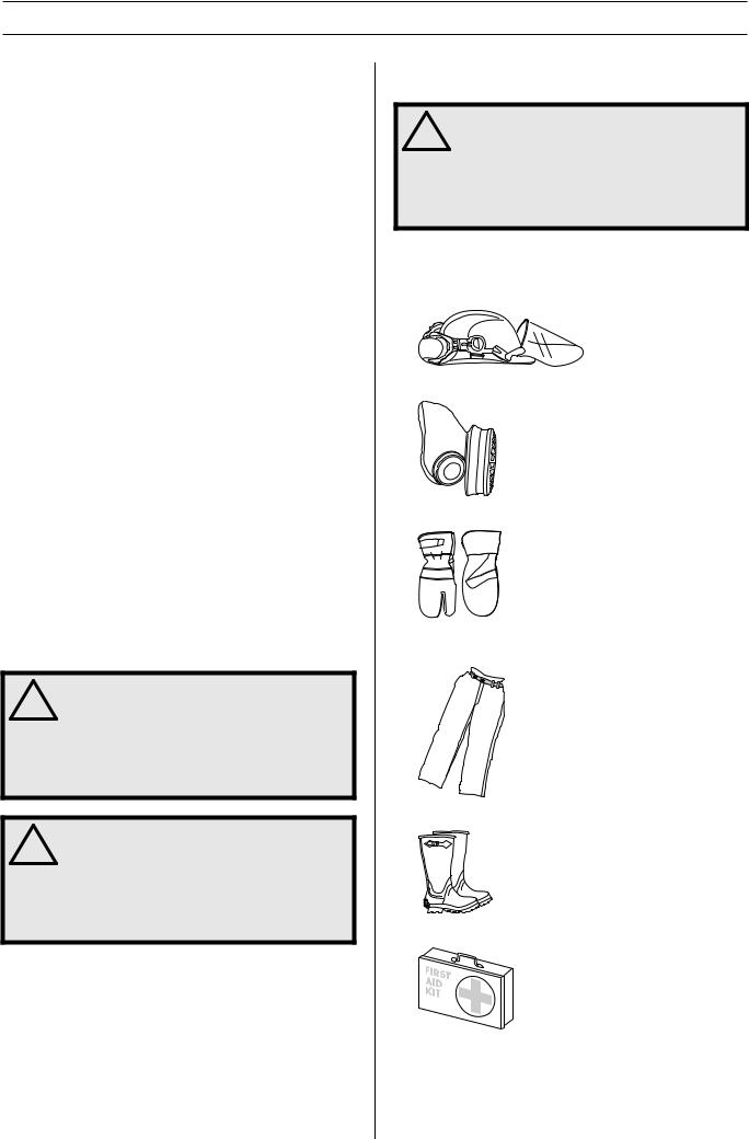
Personal protective equipment
! |
WARNING! You must use approved personal |
protective equipment whenever you use the |
|
machine. Personal protective equipment |
|
|
cannot eliminate the risk of injury but it will |
|
reduce the degree of injury if an accident |
|
does happen. Ask your dealer for help in |
|
choosing the right equipment. |
•Protective helmet
•Hearing protection
•Protective goggles or a visor
•Breathing mask
•Heavy-duty, firm grip gloves.
•Tight-fitting, heavy-duty and comfortable clothing that permits full freedom of movement.
•Boots with steel toe-caps and non-slip sole.
•Always have a first aid kit nearby.
6 – English
SAFETY INSTRUCTIONS
Machine′s safety equipment
This section describes the machine′s safety equipment, its purpose, and how checks and maintenance should be carried out to ensure that it operates correctly. See the ”What is what?” section to locate where this equipment is positioned on your machine.
! |
WARNING! Never use a machine that has |
faulty safety equipment! Safety equipment |
|
must be inspected and maintained. See |
|
|
instructions under the heading Checking, |
|
maintaining and servicing the machine’s |
|
safety equipment. If your machine does not |
|
pass all the checks, take it to a service |
|
workshop for repair. |
Checking, maintaining and servicing the machine′s safety equipment
IMPORTANT! All servicing and repair work on the machine requires special training. This is especially true of the machine′s safety equipment. If your machine fails any of the checks described below you must contact your service agent. When you buy any of our products we guarantee the availability of professional repairs and service. If the retailer who sells your machine is not a servicing dealer, ask him for the address of your nearest service agent.
Switch
The power switch should be used to start and stop the machine.
Checking the power switch
•Start the machine by pressing the power switch.
•Shut down the machine by pressing the power switch.
•A defective power switch should be replaced by an authorized service workshop.
General safety precautions
•Do not use the drilling machine without first reading and understanding the contents of this Operator’s Manual.
! |
WARNING! There is always a risk of shocks |
from electrically powered machines. Avoid |
|
unfavourable weather conditions and body |
|
|
contact with lightning conductors and metal |
|
objects. Always follow the instructions in the |
|
Operator’s manual to avoid damage. |
! |
WARNING! There is always a risk of crush |
injuries when working with products |
|
containing moving parts. Wear protective |
|
|
gloves to avoid body injuries. |
•Never use the machine if you are tired, if you have drunk alcohol, or if you are taking medication that could affect your vision, your judgement or your co-ordination.
•Wear personal protective equipment. See instructions under the heading Personal protective equipment.
•Never carry the machine by means of the cord and never pull out the plug by pulling the cord. Keep all cords and extension cords away from water, oil and sharp edges. Make sure the cord is not pinched in doors, fences or the like. Otherwise it can cause the object to become live.
•Check that the cord and extension cord are intact and in good condition. Use an extension cord intended for outdoor use. Never use the machine if the cord is damaged, hand it in to an authorized service workshop for repair.
•Do not use an extension cord while it is rolled up to avoid overheating.
•The machine should be connected to an earthed outlet socket.
•Check that the mains voltage corresponds with that stated on the rating plate on the machine.
•Never use a machine that is faulty. Carry out the checks, maintenance and service instructions described in this manual. Some maintenance and service measures must be carried out by trained and qualified specialists. See instructions under the heading Maintenance.
•Never allow anyone else to use the machine without first ensuring that they have understood the contents of the operator’s manual.
•People and animals can distract you causing you to lose control of the machine. For this reason, always remain concentrated and focused on the task.
•Be careful as clothing, long hair, and jewellery can get caught in moving parts.
Transport and storage
Do not store or transport the drilling machine with the drill bit fitted in order to protect your drilling machine and drill bits from damage.
Store the drilling machine in a lockable area so that it is out of reach of children and unauthorised persons.
Store the drilling machine and stand in dry and frost free conditions.
English – 7
PRESENTATION
Drill motor and stand
It is our wish that you will be satisfied with your product and that it will be your companion for a long time. Think of this operator′s manual as a valuable document. By following its′ content (using, service, maintenance etc) the life span and the second-hand value of the machine can be extended. If you will sell this machine, make sure that the buyer will get the operator′s manual.
A purchase of one of our products gives you access to professional help with repairs and services whenever this may be necessary. If the retailer who sells your machine is not one of our authorised dealers, ask him for the address of your nearest service workshop.
Husqvarna Construction Products has a policy of continuous product development. Husqvarna reserves the right to modify the design and appearance of products without prior notice and without further obligation introduce design modifications.
Drill motor DMS160
•DMS160 is an electric drill, intended for drilling concrete, brick and various stone materials.
•The drilling machine has a modular design and is easy to assemble.
•The machine has a speed range for drill bits with a diameter(ø) of 120 mm / 4.75 In.
•The design of the slip clutch (SMCSlide Mechanical Clutch) gives the greatest power output and it can be adjusted from outside.
•The machine is intended for stand mounted drilling.
•The machine is water cooled.
•The machine is double insulated and has power indicators.
•The machine works at its best if not overloaded, let the maximum yellow LED on the load/power indicator (LCSLoad Control System) be on. Max. 10 minutes max. load the machine must then be run without a load for 2 minutes.
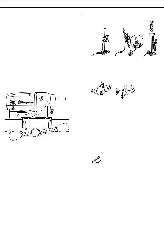
Stand DMS160
DMS160 A |
DMS160 AT |
DMS160 Gyro |
DMS160 A/AT
The stands are secured using expanding screws.
•A water collector and vacuum plate are available as accessories to suck the stand into place.
DMS160 AT
•DMS160 AT has a modular design that permits angle drilling and a rotation function.
DMS160 Gyro
•DMS160 Gyro has a modular design with telescopic stand to secure the drill motor.
•The telescopic support column has a maximum length of 3.1 metres, but can be extended an additional 0.75 metres using an extension module.
•A maximum of one extension module may be used.
•Only one spanner (24/30 mm) and an allen key (8 mm) are required to change the settings.
The drill column can be variably adjusted through 360°.
•The transport wheels can be removed.
8 – English

ASSEMBLY
Assembling the stand - DMS160 A/ AT
DMS160 A/AT
•Drill holes (15 mm) in the floor or in the wall and knock in the expander bolts.
20Bolt down the base plate. Check carefully that the expander is secured correctly.
DMS160 AT
•The drill column is mounted on the base plate’s angle bracket. Tighten the lock screw with an 8 mm allen key. The drill column can be turned through 360° and locked variably in each position using a locking screw (8 mm allen key)
•The drill column is set at the required angle by tightening the nut using a 24 mm spanner. If the vacuum plate is used, make sure the support surface is not porous and can loosen from the floor or the wall. Make sure that the vacuum pump has sufficient power to secure the vacuum plate. A suitable vacuum motor is Husqvarna VP200.
! |
WARNING! The vacuum plate must never be |
used for ceiling drilling. Careless or |
|
incorrect use can result in serious or fatal |
|
|
injury to the operator or others. |
Assembling the stand - DMS160 Gyro
DMS 160 Gyro
2 |
3 |
4
1
7
5
6
8
9
10
11
English – 9
ASSEMBLY
Drilling in walls |
|
|
|
|
6 |
5 |
2 |
|
|
|
|
|
|
|
|
|
3 |
|
|
|
|
6 |
5 |
2 |
|
7 |
|
|
|
|
|
|
|
|
|
4 |
|
|
3 |
|
|
|
|
|
|
|
|
7 |
4 |
|
|
|
|
|
|
1 |
|
|
|
1Base plate with locking screw.
2Column screw and lock screw
3Locking knob
4L-handle
5Drill column
6Column screw and lock screw
7Locking nut
8Drill motor DMS160
•Place the base plate at a drill column’s length from the wall. The support column screw should be screwed in. When drilling is to be performed at a height greater than 1.5 metres, the heavier outer tube should be turned upwards and vice versa when drilling below 1.5 metres. Check that the support column is clamped in the base plate with the locking screw.
•Clamp the telescopic column support against the ceiling. Choose the closest hole in the holed inner tube. Clamp using the support column handle and screw the last bit using a 24 mm spanner. Do not clamp too tight.
•Loosen the locking handle and rotate the drill column. Fold down the drill column using the L-handle.
•Fit the drill motor DMS160 on the drill column.
•Then turn back the drill column with the drill motor to the desired position against the wall. Lock the locking handle.
•Angle back and fold up the drill column, secure with the L- handle and nut. When angle drilling, loosen the L-handle and set the drill column at the required angle by tightening the nut using a 30 mm spanner.
•Check the position of the drill bit. Screw in the support column screw against the wall to secure the drill column. Secure with a locking nut, 30 mm. Use a wooden batten as packing. The drill column can be turned through 360° and locked variably in each position using a locking screw (8 mm allen key)
•The expander attachment can be used to provide additional anchorage of the drill column. The attachment is adjusted against the support column screw and is secured on the wall with an expansion bolt. Secure with a locking nut, 30 mm.
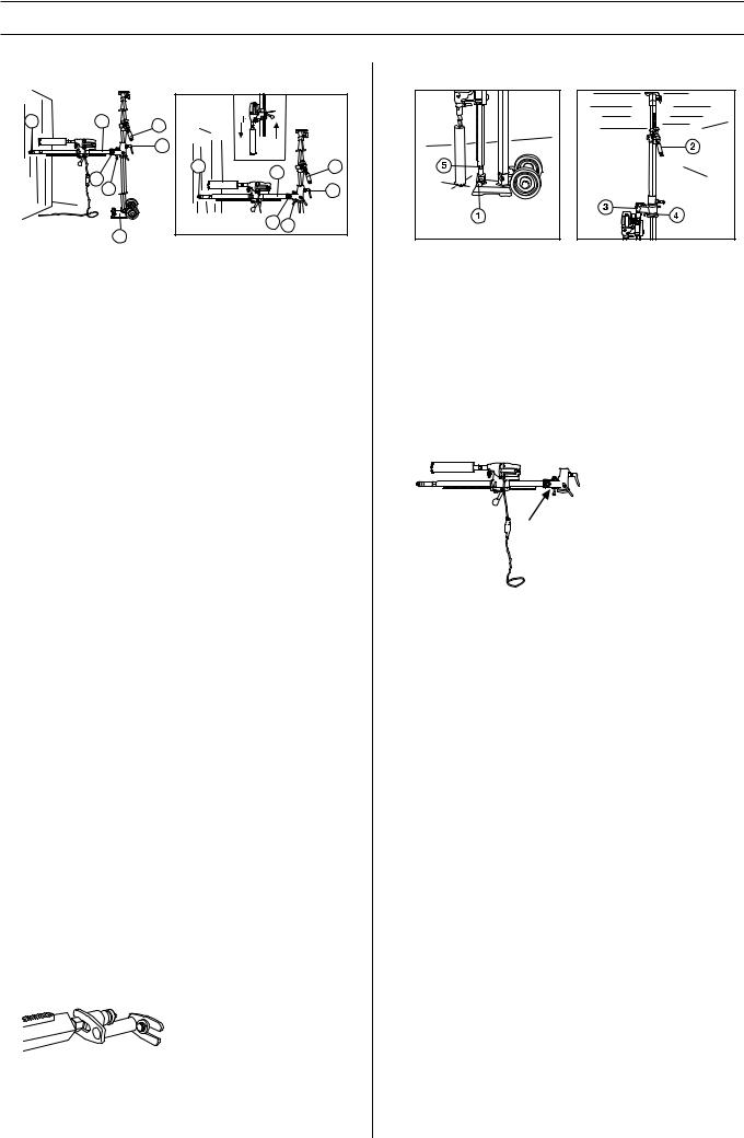
Drilling in the floor
1Locking screw
2Column screw and lock screw
3Locking knob
4L-handle
5Locking screw
•Fold down the drill column using the L-handle.
•Make sure that the support column enters the lock sleeve.
•Tighten the locking nut with a 30 mm key and lock the locking handle.
•Place the stand in the required position.
6Lock the support column in the lock sleeve with the locking screw and the nut. Tighten using the 24 and 30 mm spanners.
•Clamp the telescopic support column against the ceiling with the support column mechanism. Tighten the last bit using a 24 mm spanner, do not tighten too tight. The telescopic support column has a maximum length of 3.1 metres, but can be extended an additional 0.75 metres using an extension module.
10 – English
ASSEMBLY
Drilling in the ceiling
1Column screw and lock screw
2Locking nut
3Column screw and lock screw
•Place the stand in the required position.
•Check that the support column screw in the drill column is screwed in. Fold up and lock the drill column in the vertical position with the locking nut.
•Check that the drill bit is in the right position. Clamp the telescopic support column against the ceiling with the support column mechanism.
•Screw in the support column screw against the ceiling to secure the drill column. Secure with a locking nut, 30 mm. Use a wooden batten as packing.
•The expander attachment can be used to provide additional anchorage of the drill column. (Available as an accessory.) The attachment is adjusted against the support column screw and is secured on the wall with an expansion bolt. Secure with a locking nut, 30 mm.
! |
WARNING! The vacuum plate must never be used for ceiling drilling. Careless or incorrect use can result in serious or fatal injury to the operator or others.
English – 11
STARTING AND STOPPING
Before starting
WARNING! Note the following before ! starting:
The machine should be connected to an earthed outlet socket.
Check that the mains voltage corresponds with that stated on the rating plate on the machine. Keep people and animals well away from the working area.
WARNING! Before drilling, check that all
!locking screws are tightened well.
Serious accidents can occur if the concrete core remains in the drill when backing out the drill motor/drill from the floor, wall or ceiling.
Make sure that:
•The switch is undamaged. If not, the switch must be replaced by an authorised repairman.
•The machine and its equipment are correctly installed:
-The drill is secured properly.
-The stand is firmly attached.
-Secure the machine on the stand using a suitable method.
•Wear personal protective equipment. See instructions under the heading Personal protective equipment.
•Water cooling is connected to the machine.
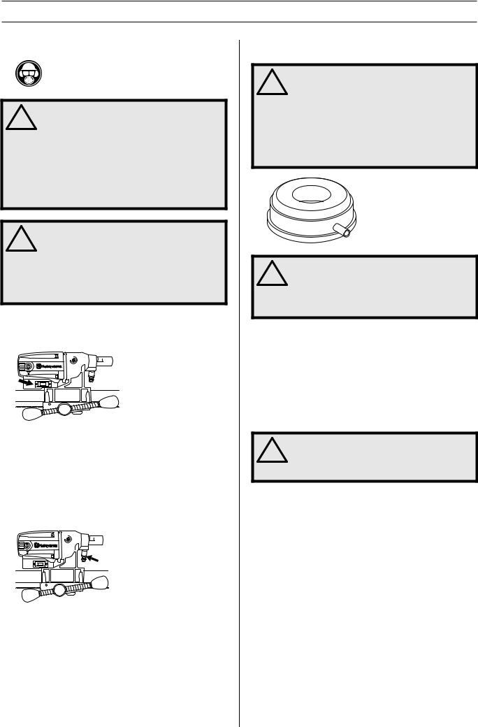
Drilling in the ceiling |
||
! |
WARNING! The vacuum plate must never be |
|
used for ceiling drilling. |
||
|
||
Use a water collector to avoid water penetrating into the machine. The machine must be covered with plastic or the like in order to prevent water penetrating into the machine, but do not cover the air intakes and air outlets.
! |
WARNING! A maximum of one extension |
|
module may be used. |
||
|
Check that no one on the floor below can be injured by falling concrete cores.
Starting
•Turn on the water cooling.
•Press in the switch fully.
•Start to feed the drill bit with the help of the feed handle.
Stopping
! |
WARNING! The drill bit continues to rotate |
for a while after the motor has been switched |
|
off. Do not stop the drill bit with your hands. |
|
|
Personal injuries can occur. |
Shut down the machine by pressing the power switch.
Cooling
Run the machine unloaded for a minute or two to cool the motor.
12 – English

WORKING TECHNIQUES
General working instructions
! |
WARNING! This section takes up the basic |
safety precautions for working with the |
|
drilling machine. This information is never a |
|
|
substitute for professional skills and |
|
experience. If you encounter a situation |
|
where you are uncertain how to proceed you |
|
should ask an expert. Contact your dealer, |
|
service agent or an experienced drilling |
|
machine user. Do not attempt any task that |
|
you feel unsure of! |
WARNING! Overexposure to vibration can
!lead to circulatory damage or nerve damage in people who have impaired circulation. Contact your doctor if you experience symptoms of overexposure to vibration. Such symptoms include numbness, loss of feeling, tingling, pricking, pain, loss of strength, changes in skin colour or condition.These symptoms normally appear in the fingers, hands or wrists. These symptoms may be increased in cold temperatures.
•Do not use the machine in bad weather, such as dense fog, rain, strong wind, intense cold, etc. Working in bad weather is tiring and can lead to dangerous conditions, e.g. slippery surfaces.
•Never start to work with the power cutter before the working area is clear and you have a firm foothold. Look out for any obstacles with unexpected movement. Ensure when cutting that no material can become loose and fall, causing operating injury.
•Remain at a distance from the drill bit when the motor is running.
•Ensure that the working area is sufficiently illuminated to create a safe working environment.
•Make sure that no pipes or electrical cables are routed in the area to be drilled.
•Ensure the cord is behind you when you start to use the machine so that the cord will not be damaged.
•Never leave the machine unsupervised with the motor running. A rotating drill bit can entail a risk of serious injury.
•Always unplug the machine during longer work breaks.
•Do not overload the machine. Overloading can damage the machine.
•Keep tools sharp and clean in order to enable safer work.
•Always check the rear side of the surface where the drill bit will emerge when drilling right through. Secure and cordon off the area and make sure that no one can be injured or material damaged.
•Always switch off the machine before you move it.
•Never work alone, always ensure there is another person close at hand. Apart from being able to receive help to assemble the machine, you can also get help if an accident should occur.
•Keep all parts in good working order and ensure that all fixtures are properly tightened.
English – 13
WORKING TECHNIQUES
Using the machine
•Keep your hands at a safe distance from the drill spindle and drill bit when the machine is running.
•Keep an eye open for oil or water leakage.
Drilling outdoors
Always use extension cables that are approved for outdoor use.
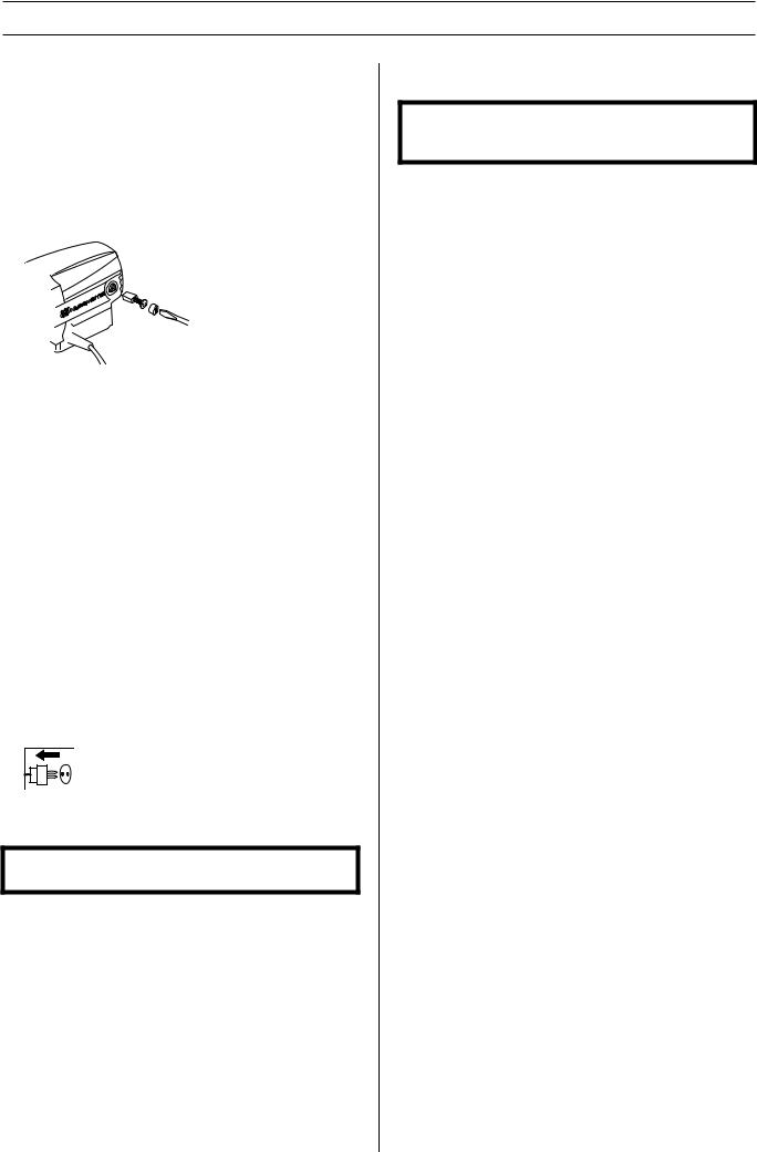
Changing the drill bit
1Pull out the plug.
2Get:
-The new drill bit.
-The supplied open-ended spanners, size 24 mm and 32 mm.
-Water-resistant grease.
3Remove the old drill bit using the open-ended spanners.
4Apply water-resistant grease to the thread of the new drill bit.
5Attach the drill bit using the open-ended spanners.
Slip clutch (SMC)
The machine is equipped with a mechanical slip clutch (SMC).
Tension the slip clutch as follows:
•Loosen the cover for the slip clutch.
 2
2
1 |
3 |
|
•Carefully lock the hook nut using a flat wide screwdriver in one of the hook nut’s four notches.
•Turn the drill spindle with a 27 mm open-ended spanner 15 degrees.
Remove the screwdriver and refit the cover on the slip clutch.
Load/power indication (LCS-Load control system).
The machine works at its best if not overloaded, let the maximum yellow LED on the load/power indicator (LCSLoad Control System) be on. Max. 10 minutes max. load the machine must then be run without a load for 2 minutes.
14 – English
MAINTENANCE
Maintenance of the drill motor
IMPORTANT! Inspection and/or maintenance should be carried out with the motor switched off and the plug disconnected.
The lifetime of your machine can be extended considerably if it is used, cared for and maintained in the proper manner.
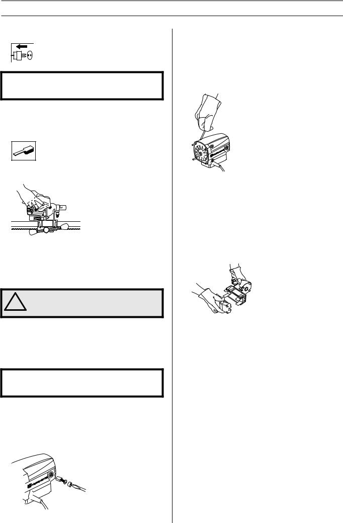
Cleaning
•Keep the machine and drill bit clean in order for drilling to be carried out safely.
•In order for the machine to always be cooled sufficiently the cooling air openings must be kept clear and clean. Blow down the machine regularly with compressed air.
Electrical Feed
! |
WARNING! Never use damaged cables that |
can cause serious, even fatal, personal |
|
injuries. |
Check that the cord and extension cord are intact and in good condition. Never use the machine if the cord is damaged, hand it in to an authorized service workshop for repair.
Repairs
IMPORTANT! All types of repairs may only be carried out by authorised repairmen. This is so that the operators are not exposed to great risks.
Replacing the motor and the gearbox
1Secure the machine with drill spindle downwards in a vice or the like.
2Remove the cover for the carbon brushes using a flat wide screwdriver.
3 Carefully remove the carbon brushes.
4Unscrew the four screws holding together the motor and gearbox.
5Loosen the ground cable from the gearbox cover (only applies to 230V).
6Carefully disassemble the machine.
7Replace the module that needs to be replaced. Use Castrol MS3 Molybdenum grease in the gearbox.
8Assemble the motor with the gearbox.
9Replace the screws.
10Screw on the brush cover.
Changing the rear section
1Loosen the four screws and the locking knob on the rear of the drill.
2Replace the two slide plates when the rear section is to be replaced.
3Bolt together the rear section using the four screws. Screw in the locking knob.
English – 15
MAINTENANCE
Replacing the carbon brushes
The carbon brushes must be removed and checked regularly. Weekly if the machine is used daily or at longer intervals if the machine is used more seldom. The area of wear should be even and undamaged.
Both carbon brushes must always be replaced as a pair, but one at a time. Do as follows:
1Remove the cover for the carbon brushes using a flat wide screwdriver.
2Carefully remove the carbon brushes. The carbon brushes must be replaced if there is less than 6 mm remaining on the brushes.
3Fit new carbon brushes.
4Screw on the brush cover.
5Let the machine idle for 10 minutes to run in the new carbon brushes.
Daily maintenance
1Check that nuts and screws are tight.
2Check that the power switch unit works smoothly.
3Clean the outside of the machine.
4Check and clean the cooling air openings.
5Check that the cord and extension cord are intact and in good condition.
Stand maintenance
Cleaning and lubrication
IMPORTANT! Remove the drill motor. For maintenance of the drill motor see maintenance of the drill motor.
•It is important that the drill stand is kept clean for functionality to be maintained.
•Clean the stand using a high pressure washer and then wipe dry.
•Lubricate the moving parts on the stand. Apply standard grease to counteract corrosion on the contact surfaces.
Repairs
IMPORTANT! All types of repairs may only be carried out by authorised repairmen. This is so that the operators are not exposed to great risks.
Daily maintenance
1Check that nuts and screws are tight.
2Clean the outside of the machine.
16 – English

TECHNICAL DATA |
|
Drill motor DMS 160 |
|
Electric motor |
Single-phase |
Rated voltage, V |
230/100-120 |
Rated output, W |
1560 |
Rated current, A |
|
230 V |
6A |
100-120 V |
13A |
Weight, kg |
5,9 |
Diameter drill bit, mm |
|
Max. diameter of the drill bit, with stand |
120 mm (4.7”) |
Spindle thread |
Int. 1/2” R |
Water connector |
G 1/4” |
Spindle speed, idle, rpm |
|
Green 1 |
1100 |
Green 2 |
980 |
Green 3 |
840 |
Spindle speed, rpm |
|
Yellow |
700 |
Red |
640 |
Noise emissions (see note 1) |
|
Sound power level, measured dB(A) |
102 |
Sound power level, guaranteed LWA dB(A) |
103 |
Sound levels (see note 2) |
|
Sound pressure level at the operators ear, dB(A) |
89 |
Vibration levels (see note 3) |
|
Handle, m/s2 |
<2,5 |
Note 1: Noise emissions in the environment measured as sound power (LWA) in conformity with EN 12348.
Note 2: Noise pressure level according to EN 12348. Reported data for noise pressure level has a typical statistical dispersion (standard deviation) of 1.0 dB(A).
Note 3: Vibration level according to EN 12348. Reported data for vibration level has a typical statistical dispersion (standard deviation) of 1 m/s2.
English – 17

|
TECHNICAL DATA |
Stand DMS 160 |
|
Height, mm |
|
DMS 160 A height, mm |
840 |
DMS 160 AT height, mm |
900 |
DMS 160 Gyro height, mm |
1900-3100 |
Stroke, mm |
600 |
Max. drill bit diameter (mm) |
120 |
Weight, kg |
|
DMS 160 A |
10,5 |
DMS 160 AT |
12 |
DMS 160 Gyro |
31,4 |
Tool kit DMS 160 AT |
0,3 |
Tool kit DMS 160 Gyro |
0,8 |
Weight, kg (extra accessory) |
|
Vacuum plate |
2,5 |
Water collector |
0,7 |
Extension module l |
2,9 |
Extension module U |
2,9 |
Expansion attachment |
0,8 |
EC-declaration of conformity
(Applies to Europe only)
Husqvarna AB, SE-433 81 Göteborg, Sweden, tel: +46-31-949000, declares under sole responsibility that drilling machine and stand Husqvarna DMS 160 drill motor, DMS 160 A/AT/Gyro from 2010’s serial number and onward (the year is stated in plain text on the type plate plus a subsequent serial number) conform with the regulations in the COUNCIL’S DIRECTIVE:
•of May 17, 2006 "relating to machinery" 2006/42/EC
•of December 15, 2004 ”relating to electromagnetic compatibility” 2004/108/EC.
•of December 12, 2006 ”relating to electrical equipment” 2006/95/EC.
The following standards have been applied: EN ISO 12100:2003, EN 55014-1:2006, EN 55014-2/A1:2001, EN 61000-3-2:2006, EN 61000-3-3/A1/A2:2005, EN 12348/A1:2009.
Göteborg December 29, 2009
Henric Andersson
Vice President, Head of Power Cutters and Construction Equipment
Husqvarna AB
(Authorized representative for Husqvarna AB and responsible for technical documentation.)
18 – English
ACLARACIÓN DE LOS SÍMBOLOS
Símbolos en la máquina:
¡ATENCIÓN! La máquina, si se utiliza de forma errónea o descuidada, puede ser una herramienta peligrosa que puede causar daños graves e incluso la muerte al usuario y a otras personas.
Lea detenidamente el manual de instrucciones y asegúrese de entender su contenido antes de utilizar la máquina.
Utilice siempre:
• Casco protector homologado
• Protectores auriculares homologados
•Gafas protectoras o visor
•Máscara respiratoria
Este producto cumple con la directiva CE vigente.
Etiquetado ecológico. El símbolo en el producto o en su envase indica que no se puede tratar este producto como desperdicio doméstico. Deberá por lo tanto depositarse en un centro de recogida adecuado para el reciclado de equipos eléctricos y electrónicos.
Haciendo que este producto sea manipulado adecuadamente, se ayuda a evitar consecuencias negativas potenciales para el medio ambiente y las personas, lo que puede ocurrir con la manipulación inadecuada como residuos del producto.
Para obtener información más detallada sobre el reciclado de este producto, contacte con la oficina municipal local, con el servicio de eliminación de desperdicios domésticos o con la tienda donde compró el producto.
Al perforar en techo, comprobar que no puede entrar agua en la máquina. Utilizar un colector de agua adecuado y cubrir la máquina con un plástico, pero sin tapar las bocas de entrada y salida de aire.
La taladradora debe ser adecuada y estar adaptada para el tamaño de la broca. El diámetro máximo de broca está indicado en la máquina.
Utilizar una broca adecuada para el trabajo a realizar.
Ø
Indicación de carga/corriente (sistema de control de carga LCS).
Comprobar que el techo es adecuado. El techo debe ser macizo.
Comprobar que la horquilla agarra en la orejeta interior. Apretar con una llave adecuada.
Fijar la tuerca con una llave de 30 mm. Controlar la tuerca de seguridad del mango en L. Comprobar que está apretada.
¡ATENCIÓN! Al taladrar se genera polvo que puede causar daños por inhalación. Utilizar una máscara respiratoria homologada. Procurar que haya buena ventilación.
Los demás símbolos/etiquetas que
aparecen en la máquina corresponden a requisitos de homologación específicos en determinados mercados.
Símbolos en el manual de instrucciones:
El control y/o mantenimiento de la máquina debe hacerse con el motor parado y el enchufe desenchufado.
Utilice siempre guantes protectores homologados.
La máquina debe limpiarse regularmente.
Control visual.
Debe utilizarse gafas protectoras o visor.
Spanish – 19

|
ÍNDICE |
Índice |
|
ACLARACIÓN DE LOS SÍMBOLOS |
|
Símbolos en la máquina: ............................................. |
19 |
Símbolos en el manual de instrucciones: .................... |
19 |
ÍNDICE |
|
Índice ........................................................................... |
20 |
¿QUÉ ES QUÉ? |
|
Componentes de la taladradora ................................... |
21 |
¿QUÉ ES QUÉ? |
|
Componentes del soporte ............................................ |
22 |
INSTRUCCIONES DE SEGURIDAD |
|
Medidas a tomar antes de utilizar una taladradora |
|
nueva ........................................................................... |
23 |
Equipo de protección personal .................................... |
23 |
Equipo de seguridad de la máquina ............................ |
24 |
Control, mantenimiento y servicio del equipo de |
|
seguridad de la máquina ............................................. |
24 |
Instrucciones generales de seguridad ......................... |
24 |
PRESENTACIÓN |
|
Motor de taladradora y soporte .................................... |
25 |
Motor de taladradora DMS160 ..................................... |
25 |
Soporte DMS160 ........................................................ |
25 |
MONTAJE |
|
Montaje del soporte - DMS160 A/AT ........................... |
26 |
Montaje del soporte - DMS160 Gyro ........................... |
26 |
ARRANQUE Y PARADA |
|
Antes de arrancar ........................................................ |
29 |
Arranque ...................................................................... |
29 |
Parada ......................................................................... |
29 |
TÉCNICA DE TRABAJO |
|
Instrucciones generales de trabajo .............................. |
30 |
Empleo de la máquina ................................................. |
31 |
MANTENIMIENTO |
|
Mantenimiento del motor de taladradora ..................... |
32 |
Mantenimiento del soporte .......................................... |
33 |
DATOS TECNICOS |
|
Motor de taladradora DMS160 ..................................... |
34 |
Soporte DMS160 ........................................................ |
35 |
Declaración CE de conformidad .................................. |
35 |
20 – Spanish
¿QUÉ ES QUÉ? |
Componentes de la taladradora
1 |
Husillo de taladradora |
8 |
Manija de fijación |
2 |
Conexión de agua |
9 |
Tornillos (4 unidades) para pieza trasera de alimentador y |
3 |
Tornillos que fijan el motor en la caja de cambios. |
|
caja de cambios |
|
|
||
4 |
Interruptor |
10 |
Empuñadura de alimentador |
|
|
||
5 |
Tapa del acoplamiento deslizante (SMC) |
11 |
Pieza trasera de alimentador |
|
|
||
6 |
Tapa de escobillas |
12 |
Ruptor de falla de tierra PRCD |
|
|
||
7 |
Indicación de carga/corriente (sistema de control de |
13 |
Llaves |
|
|
||
|
carga LCS). |
14 |
Manual de instrucciones |
Spanish – 21
¿QUÉ ES QUÉ? |
Componentes del soporte
1 |
Puntal telescópico 40 |
11 |
Mango en L |
2 |
Columna de perforación |
12 |
Manual de instrucciones |
3 |
Motor de taladradora DMS160 |
13 |
Módulo prolongador U (Disponible como accesorio.) |
4 |
Riel de pared |
14 |
Módulo prolongador I (Disponible como accesorio.) |
5 |
Puntal / mecanismo de bloqueo |
15 |
Fijación de expansión (Disponible como accesorio.) |
6 |
Placa de techo |
16 |
Colector de agua (Disponible como accesorio.) |
7 |
Placa base (GB 40 T) con ruedas de transporte |
17 |
Placa de vacío (Disponible como accesorio.) |
8 |
Placa base inclinada expansible |
18 |
Juego de herramientas DMS160 AT |
9 |
Tornillo de puntal y tornillo de fijación |
19 |
Juego de herramientas DMS160 Gyro |
10 |
Contratuerca |
|
|
22 – Spanish
Loading...