

Page 1

Maintenance and Service
Guide
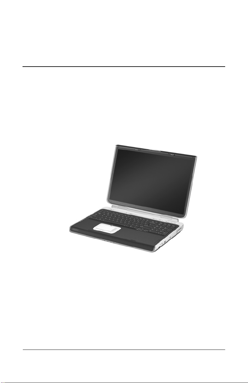
HP Pavilion Widescreen Notebook zd7000
Document Part Number: 333621-001
August 2003
This guide is a troubleshooting reference used for maintaining
and servicing the notebook. It provides comprehensive
information on identifying notebook features, components, and
spare parts; troubleshooting notebook problems; and performing
notebook disassembly procedures.
Page 2

Please check out our eBay auctions for more great
deals on Factory Service Manuals:
Page 3

© 2003 Hewlett-Packard Development Company, L.P.
Microsoft and Windows are trademarks of Microsoft Corporation in the
U.S. and/or other countries. Intel and Pentium are trademarks of Intel
Corporation in the U.S. and/or other countries. SD Logo is a trademark.
The information contained herein is subject to change without notice. The
only warranties for HP products and services are set forth in the express
warranty statements accompanying such products and services. Nothing
herein should be construed as constituting an additional warranty. HP shall
not be liable for technical or editorial errors or omissions contained herein.
Maintenance and Service Guide
HP Pavilion Widescreen Notebook zd7000
First Edition August 2003
Document Part Number: 333621-001
Page 4

Contents
1 Product Description
1.1 Models. . . . . . . . . . . . . . . . . . . . . . . . . . . . . . . . . . . . 1–2
1.2 Features . . . . . . . . . . . . . . . . . . . . . . . . . . . . . . . . . . . 1–4
1.3 Clearing a Password . . . . . . . . . . . . . . . . . . . . . . . . . 1–6
1.4 Power Management. . . . . . . . . . . . . . . . . . . . . . . . . . 1–7
1.5 External Components . . . . . . . . . . . . . . . . . . . . . . . . 1–8
1.6 Design Overview. . . . . . . . . . . . . . . . . . . . . . . . . . . 1–18
2 Troubleshooting
2.1 Computer Setup and Diagnostics Utilities . . . . . . . . 2–1
Using Computer Setup. . . . . . . . . . . . . . . . . . . . . . . . 2–2
Selecting from the File Menu . . . . . . . . . . . . . . . . . . 2–3
Selecting from the Security Menu. . . . . . . . . . . . . . . 2–4
Selecting from the Advanced Menu . . . . . . . . . . . . . 2–5
2.2 Using Diagnostics for Windows . . . . . . . . . . . . . . . . 2–7
Obtaining, Saving, or Printing Configuration
Information . . . . . . . . . . . . . . . . . . . . . . . . . . . . . . . . 2–7
Obtaining, Saving, or Printing Diagnostic
Test Information . . . . . . . . . . . . . . . . . . . . . . . . . . . . 2–8
2.3 Troubleshooting Flowcharts . . . . . . . . . . . . . . . . . . 2–10
Maintenance and Service Guide iii
Page 5

Contents
3 Illustrated Parts Catalog
3.1 Serial Number Location . . . . . . . . . . . . . . . . . . . . . . 3–1
3.2 Notebook Major Components. . . . . . . . . . . . . . . . . . 3–2
3.3 Miscellaneous Plastics Kit Components . . . . . . . . . . 3–8
3.4 Miscellaneous Cable Kit Components . . . . . . . . . . . 3–9
3.5 Mass Storage Devices . . . . . . . . . . . . . . . . . . . . . . . 3–10
3.6 Miscellaneous . . . . . . . . . . . . . . . . . . . . . . . . . . . . . 3–11
4 Removal and Replacement Preliminaries
4.1 Tools Required . . . . . . . . . . . . . . . . . . . . . . . . . . . . . 4–1
4.2 Service Considerations . . . . . . . . . . . . . . . . . . . . . . . 4–2
Plastic Parts . . . . . . . . . . . . . . . . . . . . . . . . . . . . . . . . 4–2
Cables and Connectors . . . . . . . . . . . . . . . . . . . . . . . 4–2
4.3 Preventing Damage to Removable Drives . . . . . . . . 4–3
4.4 Preventing Electrostatic Damage . . . . . . . . . . . . . . . 4–4
4.5 Packaging and Transporting Precautions . . . . . . . . . 4–4
4.6 Workstation Precautions . . . . . . . . . . . . . . . . . . . . . . 4–5
4.7 Grounding Equipment and Methods . . . . . . . . . . . . . 4–6
5 Removal and Replacement Procedures
5.1 Serial Number . . . . . . . . . . . . . . . . . . . . . . . . . . . . . . 5–2
5.2 Disassembly Sequence Chart . . . . . . . . . . . . . . . . . . 5–3
5.3 Preparing the Notebook for Disassembly . . . . . . . . . 5–4
5.4 Notebook Feet . . . . . . . . . . . . . . . . . . . . . . . . . . . . . . 5–7
5.5 Memory Expansion Board . . . . . . . . . . . . . . . . . . . . 5–8
5.6 Mini PCI Communications Board. . . . . . . . . . . . . . 5–10
5.7 Optical Drive. . . . . . . . . . . . . . . . . . . . . . . . . . . . . . 5–11
5.8 Keyboard. . . . . . . . . . . . . . . . . . . . . . . . . . . . . . . . . 5–12
5.9 Keyboard Cover . . . . . . . . . . . . . . . . . . . . . . . . . . . 5–16
iv Maintenance and Service Guide
Page 6

5.10 Display Assembly . . . . . . . . . . . . . . . . . . . . . . . . . 5–18
5.11 Top Cover . . . . . . . . . . . . . . . . . . . . . . . . . . . . . . . 5–20
5.12 System Board . . . . . . . . . . . . . . . . . . . . . . . . . . . . 5–23
5.13 RTC Battery . . . . . . . . . . . . . . . . . . . . . . . . . . . . . 5–27
5.14 Heat Sink. . . . . . . . . . . . . . . . . . . . . . . . . . . . . . . . 5–28
5.15 Processor . . . . . . . . . . . . . . . . . . . . . . . . . . . . . . . . 5–32
5.16 SD Card Slot/Infrared Module . . . . . . . . . . . . . . . 5–34
5.17 Speakers . . . . . . . . . . . . . . . . . . . . . . . . . . . . . . . . 5–36
6 Specifications
A Connector Pin Assignments
B Power Cord Set Requirements
3-Conductor Power Cord Set . . . . . . . . . . . . . . . . . . . . . . B–1
General Requirements . . . . . . . . . . . . . . . . . . . . . . . . . . . B–1
Country-Specific Requirements. . . . . . . . . . . . . . . . . . . . B–2
C Screw Listing
Contents
Index
Maintenance and Service Guide v
Page 7
1
Product Description
The HP Pavilion Widescreen Notebook zd7000 offers advanced
modularity, Intel Mobile Pentium DT processors with 64-bit
architecture, industry-leading NVIDIA graphics controllers, and
extensive multimedia support.
HP Pavilion Widescreen Notebook zd7000
Maintenance and Service Guide 1–1
Page 8
Product Description
1.1 Models
Notebook model information is shown in Tables 1-1 and 1-2.
Table 1-1
HP Pavilion Widescreen Notebook zd7000
Model Naming Conventions
Key
V P 320 Y7 80 Y Gg 10 H XXXXXX-XXX
123456789 10
Key Description Options
1 Brand/Series
designator
2 Processor type P = Intel Pentium 4 DT
3 Processor speed 320 = 3.20 GHz
4 Display type/
size/resolution
5 Hard drive size 80 = 80 GB 60 = 60 GB
6 Optical drive
designator
7 Integrated
communication/
wireless device
8 RAM 10 = 1024 MB
9 Operating system H = Windows XP Home
10 SKU#
V = Pavilion
280 = 2.80 GHz
306 = 3.06 GHz
Y = wide SXGA+
(1680 × 1050)
W = wide XGA
(1280 × 800)
Y = DVD-RW W = DVD-ROM/
G = combination modem + GB NIC
g = 802.11g Bluetooth
N = none
76 = 768 MB
266 = 2.66 GHz
7 = 17.1 in
5 = 15.4 in
CD-RW combo
51 = 512 MB
1–2 Maintenance and Service Guide
Page 9
Table 1-2
HP Pavilion Widescreen Notebook zd7000
All HP Pavilion zd7000 models feature:
■ TouchPad pointing device
■ 12-cell, lithium ion (Li-Ion) battery pack
■ 1-year warranty on parts and labor
V7999 P 320 Y7 80 Y Gg 10 H
United States DP446U ABA
V7001 P 320 Y7 80 Y Gg 76 H
Fran ce
Germany
Italy
V7020 P 280 Y7 80 Y Gg 51 H
United States DR089U ABA
V7030 P 306 Y7 80 Y Gg 10 H
United States DM790A ABA
V7001 P 306 Y7 80 Y GN 51 H
DP353E ABF
DP763E ABD
DP353E UUZ
Spain
Switzerland
United Kingdom
Product Description
DP353E ABE
DP353E ABZ
DP353E ABU
United States DM793A ABA
V7020 P 280 Y7 80 Y Gg 51 H
United States DM794A ABA
V7005 P 280 Y7 60 Y Gg 51 H
United States DP448U ABA
V7040 P 280 Y7 60 W GN 51 H
Fran ce
Germany
Italy
V7010 P 266 Y7 60 W Gg 51 H
United States DM788A ABA
V7998 P 266 W5 60 W Gg 51 H
United States DP447U ABA
Maintenance and Service Guide 1–3
DP761E ABF
DP762E ABD
DP761E ABZ
Spain
Switzerland
United Kingdom
DP761E ABE
DP761E UUZ
DP761E ABU
Page 10

Product Description
1.2 Features
■ The following processors, all with 512-KB L2 cache, are
available, varying by notebook model:
❏ Intel Pentium 4 DT 3.2-GHz processor with
Hyper-Threading front-side bus (FSB)
❏ Intel Pentium 4 DT 3.2-, 3.0-, and 2.8-GHz processors
with 800-MHz FSB
❏ Intel Pentium 4 DT 3.06-, 2.8-, and 2.66-GHz processors
with 533-MHz FSB
■ 17.0- or 15.4-inch wide XGA (1490×900) TFT display with
over 16.7 million colors, varying by notebook model
■ NVIDIA GeForce FX Go5000 with 128-MB video memory,
NVIDIA GeForce FX Go5000 with 64-MB video memory, or
NVIDIA GeForce 4 440 Go with 64-MB video memory,
varying by notebook model
■ 80-, 60-, or 40-GB high-capacity hard drive, varying by
notebook model
■ 256-MB DDR Synchronous DRAM (SDRAM) at 333 MHz,
expandable to 2.0 GB
■ Microsoft Windows XP Home or XP Pro, varying by
notebook model
■ Full-size Windows 98 keyboard with integrated numeric
keypad
■ TouchPad pointing device with on/off button and dedicated
vertical scroll up/down pad
■ Integrated Secure Digital (SD) flash media slot
■ Integrated 10/100BASE-T Ethernet local area network
(LAN) network interface card (NIC) with RJ-45 connector
■ Integrated wireless support for Mini PCI 802.11b/g and
Bluethumb LAN devices
1–4 Maintenance and Service Guide
Page 11

Product Description
■ Support for one Type II PC Card slot with support for both
32-bit (CardBus) and 16-bit PC Cards
■ External 135-watt AC adapter with power cord
■ 12-cell Li-Ion battery pack
■ Harman/Kardon stereo speakers
■ Support for the following optical drives:
❏ 24X Max DVD/CD-RW combination drive
❏ 8X Max DVD-RW drive
❏ 24X Max CD-ROM drive
■ Connectors:
❏ SD Card
❏ Infrared
❏ 1 Type II PC Card slot
❏ RJ-11 (modem)
❏ RJ-45 (network interface card, [NIC])
❏ 4 Universal Serial Bus (USB) v. 2.0
❏ S-Video
❏ Parallel
❏ External monitor
❏ DC power
❏ Docking
❏ IEEE 1394 digital
❏ Microphone
❏ Stereo speaker/headphone
Maintenance and Service Guide 1–5
Page 12

Product Description
1.3 Clearing a Password
If the notebook you are servicing has an unknown password,
follow these steps to clear the password. These steps also
clear CMOS:
1. Prepare the notebook for disassembly (refer to Section 5.3,
“Preparing the Notebook for Disassembly,” for more
information).
2. Remove the real time clock (RTC) battery (refer to
Section 5.13, “RTC Battery”).
3. Wait approximately 5 minutes.
4. Replace the RTC battery and reassemble the notebook.
5. Connect AC power to the notebook. Do not reinsert any
battery packs at this time.
6. Turn on the notebook.
All passwords and all CMOS settings have been cleared.
1–6 Maintenance and Service Guide
Page 13

1.4 Power Management
The notebook comes with power management features that
extend battery operating time and conserve power. The notebook
supports the following power management features:
■ Standby
■ Hibernation
■ Setting customization by the user
■ Hotkeys for setting the level of performance
■ Battery calibration
■ Lid switch Standby/resume
■ Power/Standby button
■ Advanced Configuration and Power Management (ACPM)
compliance
Product Description
Maintenance and Service Guide 1–7
Page 14
Product Description
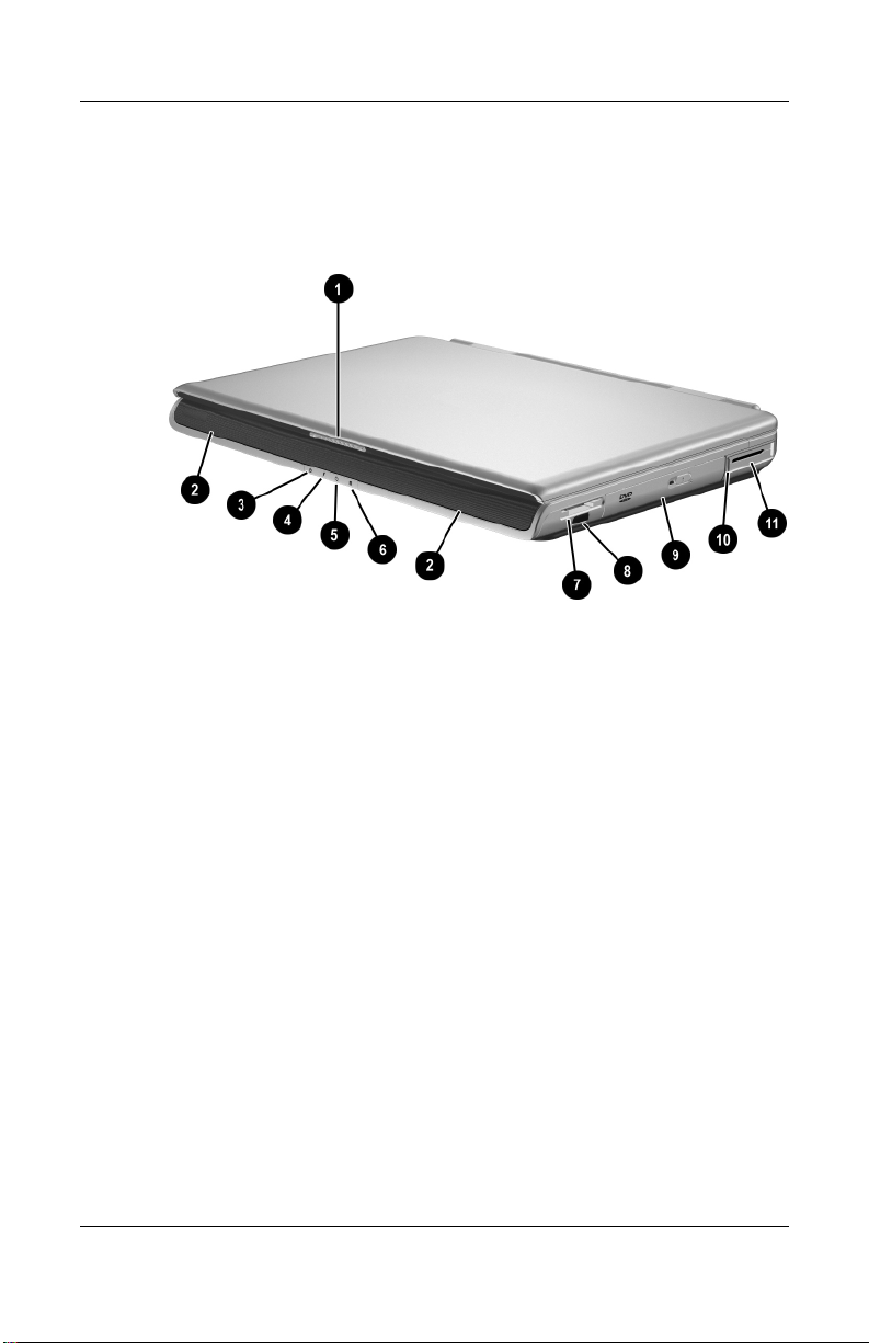
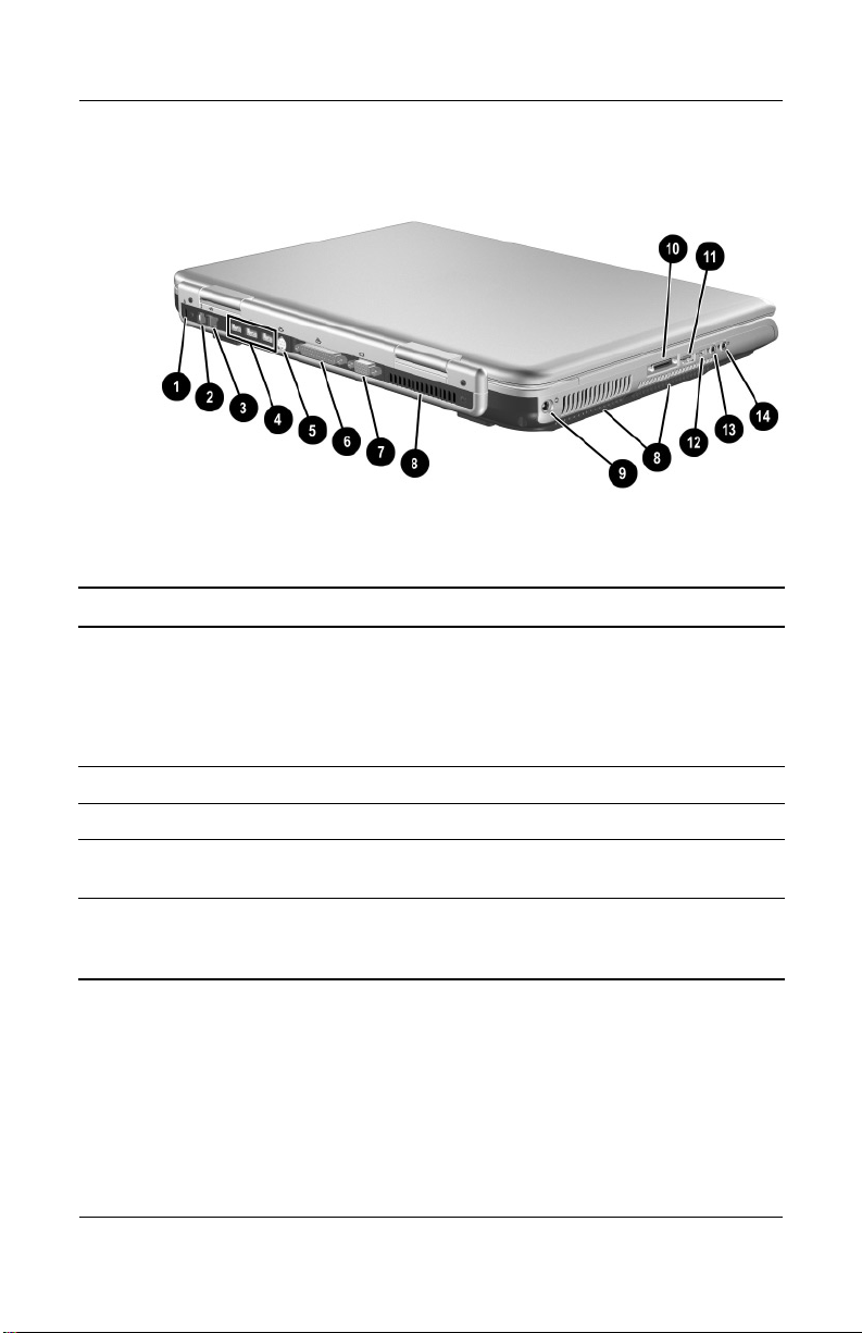
1.5 External Components
The external components on the front panel and right side of the
notebook are shown below and described in Table 1-3.
Front Panel and Right-Side Components
1–8 Maintenance and Service Guide
Page 15

Table 1-3
Front and Right Side Components
Item Component Function
1 Display release latch Opens the notebook.
2 Stereo speakers (2) Produce stereo sound.
Product Description
3 Integrated Drive
Electronics (IDE)
drive light
4 Battery light
On: The internal hard drive or optical drive
is being accessed.
■ On: The notebook is receiving battery
power.
■ Amber: A battery pack is charging.
■ Green: A battery pack is fully charged.
■ Flashing: A battery pack is
malfunctioning and might need to be
replaced.
5 AC power light On: The notebook is receiving AC power.
6 Power/Standby light On: Notebook is turned on.
Flashing: Notebook is in Standby.
7 Digital Media slot Supports SD, MMC, Memory Stick, and
SmartMedia.
8 Infrared port Provides wireless communication between
the notebook and an optional
IrDA-compliant device.
9 Optical drive Supports an optical disc.
10 PC Card eject button Ejects an optional PC Card from the
PC Card slot.
11 PC Card slot Supports an optional Type I or Type II 32-bit
(CardBus) or 16-bit PC Card.
Maintenance and Service Guide 1–9
Page 16
Product Description
The external components on the rear panel and left side are shown
below and described in Table 1-4.
Rear Panel and Left-Side Components
Table 1-4
Rear Panel and Left-Side Components
Item Component Function
1 Security cable slot Attaches an optional security cable to the
✎
2 RJ-11 telephone jack Connects a modem cable.
3 RJ-45 network jack Connects an Ethernet network cable.
4 USB connectors (3) Connect optional 2.0-compliant USB
5 S-Video jack Connects an optional S-Video device, such
1–10 Maintenance and Service Guide
The purpose of security solutions is to act as a deterrent. These
solutions do not prevent the product from being mishandled or
stolen.
notebook.
devices.
as a television, VCR, camcorder, projector,
or video capture card.
Page 17

Product Description
Table 1-4
Rear Panel and Left-Side Components
Item Component Function
6 Parallel connector Connects an optional parallel device such
as a printer.
7 External monitor
connector
8 Vents (3) Allow airflow to cool internal components.
Ä
9 Power connector Connects an AC adapter cable.
10 HP notebook
11 USB connector Connects optional 2.0-compliant USB
12 1394 connector Connects an optional 1394 device such as
13 Microphone jack Connects an optional monaural or stereo
14 Audio line-out jack Connects optional headphone or powered
To prevent overheating, use the notebook only on hard surfaces that
cannot obstruct the vents. Do not allow a soft surface, such as
bedding, clothing, or a thick rug, to block airflow.
expansion base
connector
Connects an optional VGA external monitor
or projector.
Connects to an optional expansion base.
devices.
a camcorder or digital camera.
microphone.
stereo speakers. Also connects the audio
function of an audio/video device such as a
television or VCR.
(Continued)
Maintenance and Service Guide 1–11
Page 18
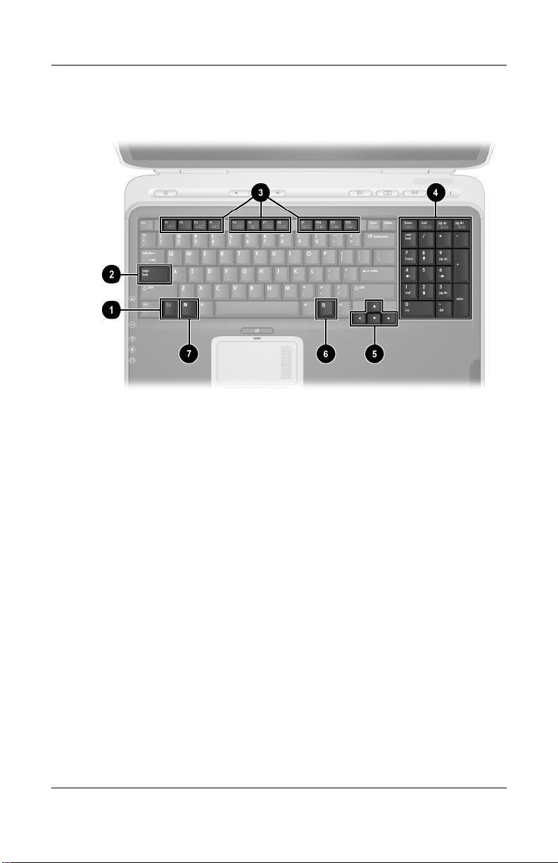
Product Description
The notebook keyboard components are shown below and
described in Table 1-5.
Keyboard Components
1–12 Maintenance and Service Guide
Page 19

Product Description
Table 1 - 5
Keyboard Components
Item Component Function
1 fn key Executes frequently used system
functions when pressed in combination
with another key.
2 caps lock key Enables caps lock and turns on the caps
3 f1 through f12 function
keys
4 Keypad keys (17) Standard numeric keypad.
5 Cursor control keys Move the cursor around the screen.
6 Applications key Displays a shortcut menu for items
7 Microsoft logo key Displays the Windows Start menu.
lock light.
Perform system and application tasks.
When combined with the fn key, the
function keys f1 and f3 through f12 perform
additional tasks as hotkeys.
beneath the pointer.
Maintenance and Service Guide 1–13
Page 20
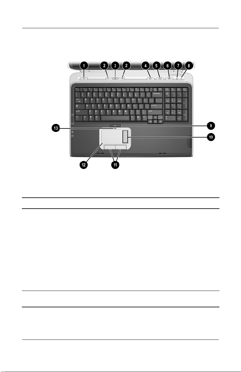
Product Description
The notebook top components are shown below and described in
Table 1-6.
Top Components
Table 1-6
Top Components
Item Component Function
1 Power button When the notebook is:
■ Off, press to turn on the notebook.
■ On, briefly press to initiate Hibernation.
■ In Standby, briefly press to resume from
Standby.
■ In Hibernation, briefly press to restore
from Hibernation.
Power/Standby light
■ On: Notebook is turned on.
■ Flashing: Notebook is in Standby.
2 Volume control
buttons (2)
1–14 Maintenance and Service Guide
Increase or decrease system volume.
Page 21

Product Description
Table 1-6
Top Components
Item Component Function
3 Mute button Mutes or restores volume.
Mute light On: Volume is muted.
4 Media button Launches a multimedia application.
5 Picture button Launches a digital imaging application.
✎
The settings for the media and picture buttons can be changed.
Refer to the “Using Custom Assignments and Schemes” section in
Chapter 3 of the Startup and Reference Guide for information on
reassigning these buttons to other applications.
(Continued)
6 Wireless on/off button Turns the wireless network device on
Wireless on/off light On: an integrated wireless device has been
7 Caps lock light On: Caps lock is on.
8 Num lock light On: Num lock is on.
9 TouchPad on/off
button
10 TouchPad scroll zone Scrolls upward or downward.
11 Left and right
TouchPad buttons
12 TouchPad Moves the pointer and selects or activates
13 TouchPad light On: TouchPad is enabled.
and off.
enabled.
Enables/disables the TouchPad.
Function like the left and right buttons on an
external mouse.
items on the screen.
Maintenance and Service Guide 1–15
Page 22
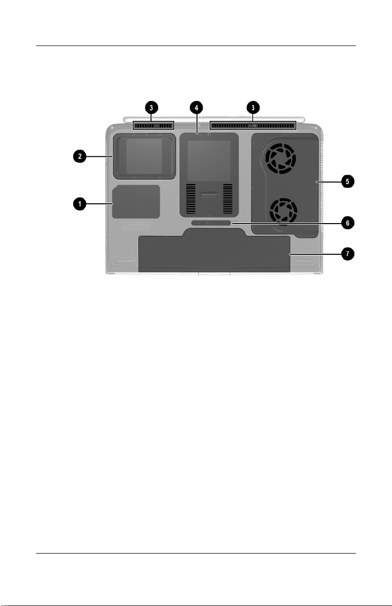
Product Description
The external components on the bottom of the notebook are
shown below and described in Table 1-7.
Bottom Components
1–16 Maintenance and Service Guide
Page 23

Product Description
Table 1-7
Bottom Components
Item Component Function
1 Labels area Contains the notebook serial
number and other applicable
regulatory labels.
2 Hard drive bay Holds the internal hard drive.
3 Vents (3) Allow airflow to cool internal
components.
Ä
To prevent overheating, do not obstruct vents. Using the notebook
on a soft surface, such as a pillow, blanket, rug, or thick clothing,
can block airflow.
4 Memory expansion/Mini PCI
communication compartment
5 Fan compartment Contains the heat sink and the two
6 Battery release latch Releases a battery pack from the
7 Battery bay Holds the battery pack.
Contains two memory slots for
optional 256-, 512-, or 1024-MB
memory modules and one slot for
a Mini PCI wireless card.
system fans.
battery bay.
Maintenance and Service Guide 1–17
Page 24

Product Description
1.6 Design Overview
This section presents a design overview of key parts and features
of the notebook. Refer to Chapter 3, “Illustrated Parts Catalog,”
to identify replacement parts, and Chapter 5, “Removal and
Replacement Procedures,” for disassembly steps.
The system board provides the following device connections:
■ Memory expansion board
■ Mini PCI communications devices
■ Hard drive
■ Display
■ Keyboard and TouchPad
■ Audio
■ Intel Pentium 4 DT processors
■ Fan
■ PC Card
The notebook uses an electrical fan for ventilation. The fan is
controlled by a temperature sensor and is designed to turn on
automatically when high temperature conditions exist. These
conditions are affected by high external temperatures, system
power consumption, power management/battery conservation
configurations, battery fast charging, and software applications.
Exhaust air is displaced through the ventilation grill located on
the left side of the notebook.
CAUTION: To properly ventilate the notebook, allow at least a 7.6-cm
Ä
(3-inch) clearance on the left and right sides of the notebook.
1–18 Maintenance and Service Guide
Page 25

2
Troubleshooting
WARNING: Only authorized technicians trained by HP should repair
this equipment. All troubleshooting and repair procedures are detailed
Å
to allow only subassembly/module level repair. Because of the
complexity of the individual boards and subassemblies, do not attempt
to make repairs at the component level or modifications to any printed
wiring board. Improper repairs can create a safety hazard. Any
indication of component replacement or printed wiring board
modification may void any warranty or exchange allowances.
2.1 Computer Setup and Diagnostics Utilities
The notebook features two system management utilities:
■ Computer Setup—A system information and customization
utility that can be used even when your operating system is
not working or will not load. This utility includes settings that
are not available in Windows.
Maintenance and Service Guide 2–1
Page 26

Troubleshooting
■ Diagnostics for Windows—A system information and
diagnostic utility that is used within the Windows operating
system. Use this utility whenever possible to:
❏ Display system information.
❏ Test system components.
❏ Troubleshoot a device configuration problem in
Windows XP Professional or Windows XP Home.
It is not necessary to configure a device connected to a USB
✎
connector on the notebook or to an optional expansion base.
Using Computer Setup
Information and settings in Computer Setup are accessed from
the File, Security, or Advanced menus:
1. Turn on or restart the notebook. Press
F10 = ROM-Based Setup message is displayed in the lower
left corner of the screen.
f10 while the
❏ To change the language, press f2.
❏ To view navigation information, press f1.
❏ To return to the Computer Setup menu, press esc.
2. Select the File, Security, or Advanced menu.
3. To close Computer Setup and restart the notebook:
❏ Select File > Save Changes and Exit and press enter.
-or-
❏ Select File > Ignore Changes and Exit and press enter.
4. When you are prompted to confirm your action, press f10.
2–2 Maintenance and Service Guide
Page 27

Selecting from the File Menu
Table 2 - 1
File Menu
Select To Do This
Troubleshooting
System Information
■ View identification information about the
notebook, an expansion base, and any
battery packs in the system.
■ View specification information about the
processor, memory and cache size, and
system ROM.
Save to Floppy Save system configuration settings to a diskette.
Restore from Floppy Restore system configuration settings from a
diskette.
Restore Defaults Replace configuration settings in Computer
Setup with factory default settings. Identification
information is retained.
Ignore Changes and Exit Cancel changes entered during the current
Save Changes and Exit Save changes entered during the current
session, then exit and restart the notebook.
session, then exit and restart the notebook.
Maintenance and Service Guide 2–3
Page 28

Troubleshooting
Selecting from the Security Menu
Table 2 - 2
Security Menu
Select To Do This
Setup Password Enter, change, or delete a Setup password.
The Setup password is called an administrator
password in Computer Security, a program
accessed from the Windows Control Panel.
Power-on Password Enter, change, or delete a power-on password.
DriveLock Passwords Enable/disable DriveLock; change a DriveLock
Password Options
(Password options can be
selected only when a
power-on password has
been set.)
Device Security Enable/disable:
User or Master password.
DriveLock Settings are accessible only
✎
when you enter Computer Setup by
turning on (not restarting) the notebook.
Enable/disable:
■ QuickLock
■ QuickLock on Standby
■ QuickBlank
To enable QuickLock on Standby or
✎
QuickBlank, you must first enable
QuickLock.
■ Ports or diskette drives*
■ Diskette write*
■ CD-ROM or diskette startup
Settings for a DVD-ROM can be
✎
entered in the CD-ROM field.
System IDs Enter identification numbers for the notebook,
*Not applicable to SuperDisk LS-120 drives.
an expansion base, and all battery packs in the
system.
2–4 Maintenance and Service Guide
Page 29

Selecting from the Advanced Menu
Table 2 - 3
Advanced Menu
Select To Do This
Language Change the Computer Setup language.
Boot Options Enable/disable:
■ QuickBoot, which starts the notebook more
quickly by eliminating some startup tests.
(If you suspect a memory failure and want
to test memory automatically during startup,
disable QuickBoot.)
■ MultiBoot, which sets a startup sequence that
can include most bootable devices and media
in the system.
Device Options
■ Enable/disable the embedded numeric
keypad at startup.
■ Enable/disable multiple standard pointing
devices at startup. (To set the notebook to
support only a single, usually nonstandard,
pointing device at startup, select Disable.)
■ Enable/disable USB legacy support for a
USB keyboard. (When USB legacy support
is enabled, the keyboard works even when
a Windows operating system is not loaded.)
■ Set an optional external monitor or overhead
projector connected to a video card in an
expansion base as the primary device.
(When the notebook display is set as
secondary, the notebook must be shut down
before undocking from an expansion base.)
Troubleshooting
Maintenance and Service Guide 2–5
Page 30

Troubleshooting
Table 2 - 3
Advanced Menu
Select To Do This
(Continued)
Device Options
(continued)
■ Change the parallel port mode from
Enhanced Parallel Port (EPP, the default
setting) to standard, bidirectional, EPP, or
Enhanced Capabilities Port (ECP).
■ Set video-out mode to NTSC (default), PAL,
NTSC-J, or PAL-M.*
■ Enable/disable all settings in the SpeedStep
window. (When Disable is selected, the
notebook runs in Battery Optimized mode.)
■ Specify how the notebook recognizes
multiple identical expansion bases that are
identically equipped. Select Disable to
recognize the expansion bases as a single
expansion base; select Enable to recognize
the expansion bases individually, by serial
number.
■ Enable/disable the reporting of the processor
serial number by the processor to the
software.
HDD Self Test Options Run a quick comprehensive self test on hard
*Video modes vary even within regions. However, NTSC is common in North
America; PAL, in Europe, Africa, and the Middle East; NTSC-J, in Japan; and
PAL-M, in Brazil. Other South and Central American regions can use NTSC,
PAL, or PAL-M.
drives in the system that support the test
features.
2–6 Maintenance and Service Guide
Page 31

Troubleshooting
2.2 Using Diagnostics for Windows
When you access Diagnostics for Windows, a scan of all system
components is displayed on the screen before the diagnostics
window opens.
You can display more or less information from anywhere within
Diagnostics for Windows by selecting Level on the menu bar.
Diagnostics for Windows is designed to test HP components.
If non-HP components are tested, the results might be
inconclusive.
Obtaining, Saving, or Printing Configuration Information
1. Access Diagnostics for Windows by selecting Start >
Settings > Control Panel > Diagnostics for Windows.
2. Select Categories, then select a category from the
drop-down list.
❏ To save the information, select File > Save As.
❏ To print the information, select File > Print.
3. To close Diagnostics for Windows, select File > Exit.
Maintenance and Service Guide 2–7
Page 32

Troubleshooting
Obtaining, Saving, or Printing Diagnostic Test Information
1. Access Diagnostics for Windows by selecting Start >
Settings > Control Panel > Diagnostics for Windows.
2. Select the Test tab.
3. In the scroll box, select the category or device you want
to test.
4. Select a test type:
❏ Quick Test—Runs a quick, general test on each device
in a selected category.
❏ Complete Test—Performs maximum testing on each
device in a selected category.
❏ Custom Test—Performs maximum testing on a selected
device.
◆ To run all tests for your selected device, select the
Check All button.
◆ To run only the tests you select, select the Uncheck
All button, then select the check box for each test you
want to run.
5. Select a test mode:
❏ Interactive Mode—Provides maximum control over the
testing process. You determine whether the test was
passed or failed. You might be prompted to insert or
remove devices.
❏ Unattended Mode—Does not display prompts. If errors
are found, they are displayed when testing is complete.
2–8 Maintenance and Service Guide
Page 33

Troubleshooting
6. Select the Begin Testing button.
7. Select a tab to view a test report:
❏ Status tab—Summarizes the tests run, passed, and failed
during the current testing session.
❏ Log tab—Lists tests run on the system, the number of
times each test has run, the number of errors found on
each test, and the total run time of each test.
❏ Error tab—Lists all errors found in the notebook with
the corresponding error codes.
8. Select a tab to save the report:
❏ Log tab—Select the Log tab Save button.
❏ Error tab—Select the Error tab Save button.
9. Select a tab to print the report:
❏ Log tab—Select File > Save As, then print the file from
your folder.
Maintenance and Service Guide 2–9
Page 34

Troubleshooting
2.3 Troubleshooting Flowcharts
Table 2-4
Troubleshooting Flowcharts Overview
Flowchart Description
2.1 Initial troubleshooting
2.2 No power, part 1
2.3 No power, part 2
2.4 No power, part 3
2.5 No power, part 4
2.6 No video, part 1
2.7 No video, part 2
2.8 Nonfunctioning expansion base
2.9 No operating system (OS) loading
2.10 No OS loading from hard drive, part 1
2.11 No OS loading from hard drive, part 2
2.12 No OS loading from hard drive, part 3
2.13 No OS loading from diskette drive
2.14 No OS loading from CD- or DVD-ROM drive
2.15 No audio, part 1
2.16 No audio, part 2
2.17 Nonfunctioning device
2.18 Nonfunctioning keyboard
2.19 Nonfunctioning pointing device
2.20 No network or modem connection
2–10 Maintenance and Service Guide
Page 35

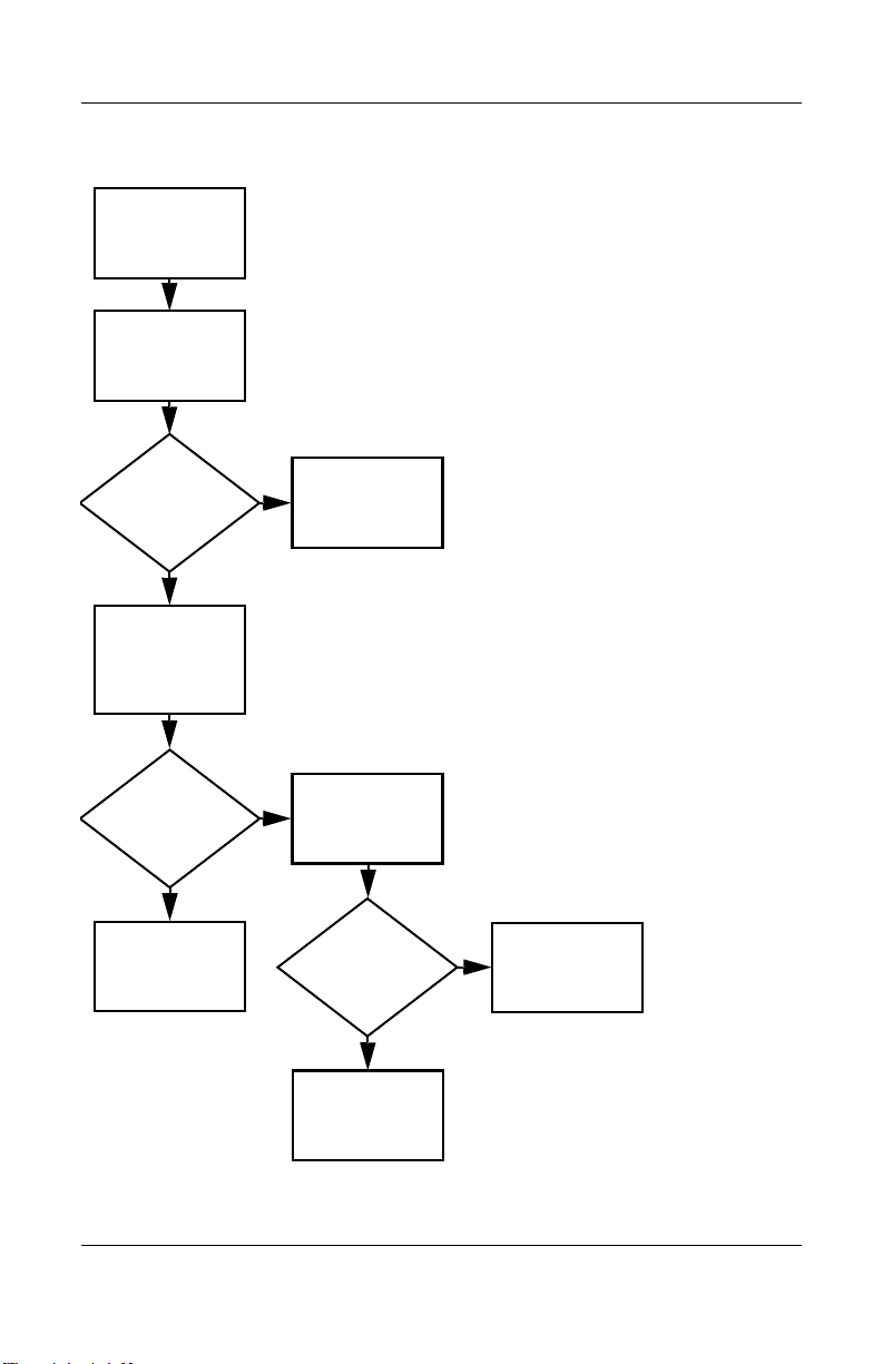
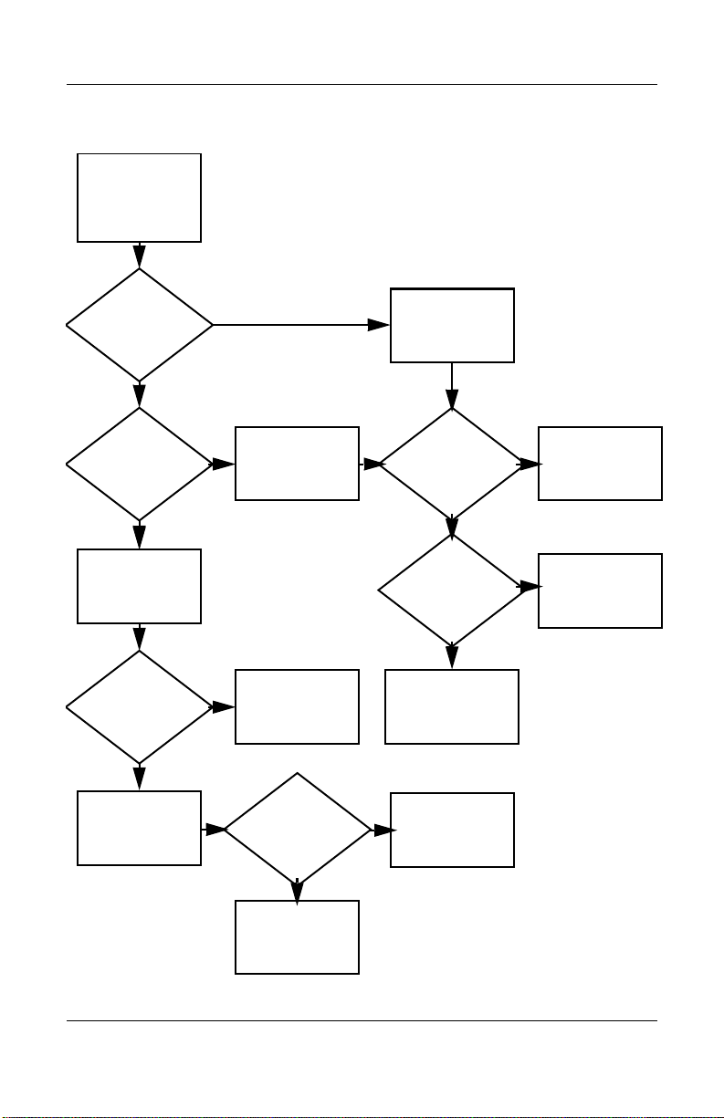
Flowchart 2.1—Initial Troubleshooting
Begin
troubleshooting.
N
Is there
power?
Y
N
Beeps,
LEDs, or error
messages?
Y
N
Is there video?
(no boot)
Y
N
Is the OS
loading?
Y
N
Is there
sound?
Y
Go to
Flowchart 2.2,
No Power.
Check
LED board,
speaker
connections.
Go to
Flowchart 2.6,
No Video.
Go to
Flowchart 2.9,
No OS Loading.
Go to
Flowchart 2.15,
No Audio.
All drives
working?
Y
Keyboard/
pointing
device
working?
Y
Connecting
to network
or modem?
Y
End
Troubleshooting
N
Flowchart 2.17,
Nonfunctioning
N
Flowchart 2.18,
Nonfunctioning
or Flowchart 2.19,
Nonfunctioning
Pointing Device.
N
Flowchart 2.20,
No Network or
Go to
Device.
Go to
Keyboard
Go to
Modem.
Maintenance and Service Guide 2–11
Page 36

Troubleshooting
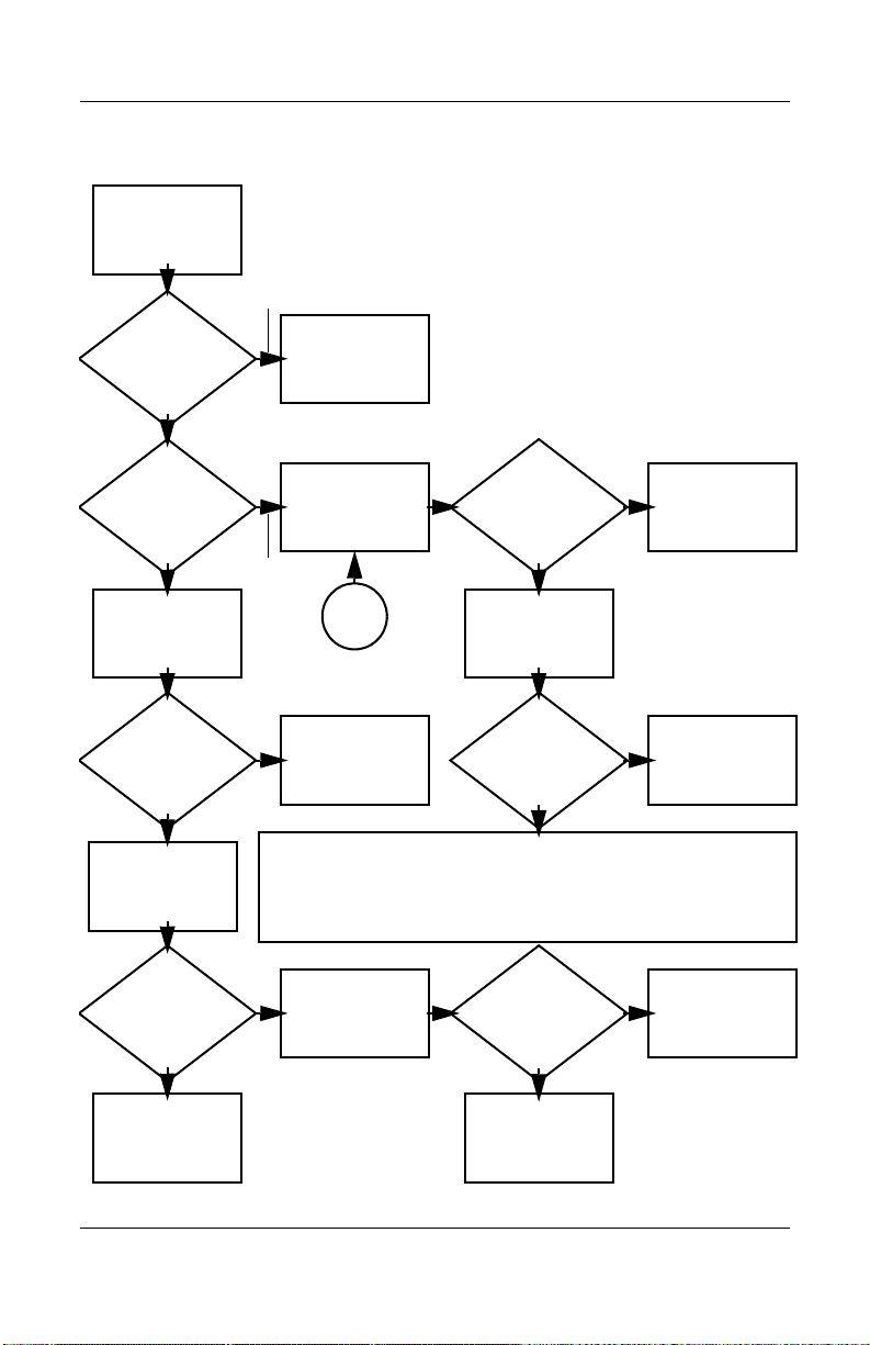
Flowchart 2.2—No Power, Part 1
No power
(power LED
is off).
Remove from
expansion base
(if applicable).
N
Power up
on battery
power?
*Reset
power.
Y
N
Power up
on AC
power?
*Reset
power.
Y
Y
Power up in
expansion
base?
Done
N
1. Reseat the power cables in the
expansion base and at the AC outlet.
2. Ensure the AC power source is active.
3. Ensure that the power strip is working.
YN
Power up
Done
in expansion
base?
N
Power up
on battery
power?
Go to
Flowchart 2.3,
No Power,
Part 2.
Y
N
Power up
on AC
power?
Go to
Flowchart 2.4,
No Power,
Part 3.
Y
*NOTES:
1. On some models, there is a separate
reset button.
2. On some models, the notebook can be
reset using the Standby switch and
either the lid switch or the main power
switch.
Go to
Flowchart 2.8,
Nonfunctioning
Expansion Base.
2–12 Maintenance and Service Guide
Page 37
Flowchart 2.3—No Power, Part 2
Continued from
Flowchart 2.2,
No Power, Part 1.
Visually check for
debris in battery
socket and clean
if necessary.
Y
Troubleshooting
Power on?
N
Check battery by
recharging it,
moving it to
another notebook,
or replacing it.
Power on?
Y
Done
Done
N
Replace
power supply
(if applicable).
N
Go to
Power on?
Flowchart 2.4,
No Power,
Part 3.
Y
Done
Maintenance and Service Guide 2–13
Page 38

Troubleshooting
Flowchart 2.4—No Power, Part 3
Continued from
Flowchart 2.3,
No Power, Part 2.
Plug directly
into AC outlet.
Y
Power LED
on?
N
Reseat AC adapter
in notebook and
at power source.
Power on?
N
Power outlet
active?
Y
Replace
power cord.
Power on?
Done
Y
Done
N
Try different
outlet.
Internal or
external AC
adapter?
Internal
Flowchart 2.5,
No Power,
External
Replace external
AC adapter.
N
Go to
Power on?
Part 4.
Y
Y
Done
Done
N
2–14 Maintenance and Service Guide
Page 39

Flowchart 2.5—No Power, Part 4
Continued from
Flowchart 2.4,
No Power, Part 3.
Open
notebook.
Troubleshooting
Loose or
damaged
parts?
N
Close
notebook and
retest.
Power on?
Y
Done
Y
Reseat loose
components and
boards and
replace damaged
items.
N
Replace the following items (if applicable).
Check notebook operation after each
replacement:
1. Internal DC-DC converter*
2. Internal AC adapter
3. Processor board*
4. System board*
*NOTE: Replace these items as a set to
prevent shorting out among components.
Maintenance and Service Guide 2–15
Page 40
Troubleshooting
Flowchart 2.6—No Video, Part 1
No video.
Expansion
Base
Stand-alone
or expansion
base?
Go to
Flowchart 2.7,
No Video, Part 2.
*NOTE: To change from internal to
external display, use the hotkey
combination.
Stand-alone
Y
Internal or
external
display*?
External
Adjust
brightness.
Internal
Y
Video OK? Done
N
Check for bent
pins on cable.
N
Video OK?
Adjust
brightness.
Video OK? Done
N
A
Press lid
switch to ensure
operation.
Y
Video OK? Done
N
Replace the following one at a time. Test after each replacement.
1. Cable between notebook and notebook display (if applicable)
2. Inverter board (if applicable)
3. Display
4. System board
N
Try
another
display.
Internal and
external
video OK?
Replace
system
board.
YY
Done
2–16 Maintenance and Service Guide
Done
Page 41

Flowchart 2.7—No Video, Part 2
Continued from
Flowchart 2.6,
No Video, Part 1.
Remove
notebook from
expansion base,
if connected.
Troubleshooting
Adjust
display
brightness.
N
Video OK?
No Video, Part 1.
Y
Check that notebook is properly
seated in expansion base, for
bent pins on cable, and for
monitor connection.
Y
Video OK?
N
Adjust external
monitor display.
Go to “A” in
Flowchart 2.6,
Done
Check brightness
of external
monitor.
Video OK?
N
Try another
external
monitor.
Internal
and external
video OK?
N
Go to
Flowchart 2.8,
Nonfunctioning
Expansion Base.
Y
Done
Y
Done
Maintenance and Service Guide 2–17
Page 42
Troubleshooting
Flowchart 2.8—Nonfunctioning Expansion Base
(if applicable)
Nonfunctioning
expansion base.
Reseat power
cord in expansion
base and
power outlet.
Check voltage
setting on
expansion base.
Reset monitor
cable connector at
expansion base.
Expansion
base
operating?
N
Remove
notebook, reseat
all internal parts,
and replace any
damaged items in
expansion base.
Reinstall
notebook into
expansion base.
Y
Expansion
base
operating?
Y
Done
N
Replace the following expansion base
components one at a time. Check
notebook operation after each
replacement.
1. Power supply
2. I/O board
3. Backplane board
4. Switch box
5. Expansion base motor mechanism
Done
2–18 Maintenance and Service Guide
Page 43

Troubleshooting
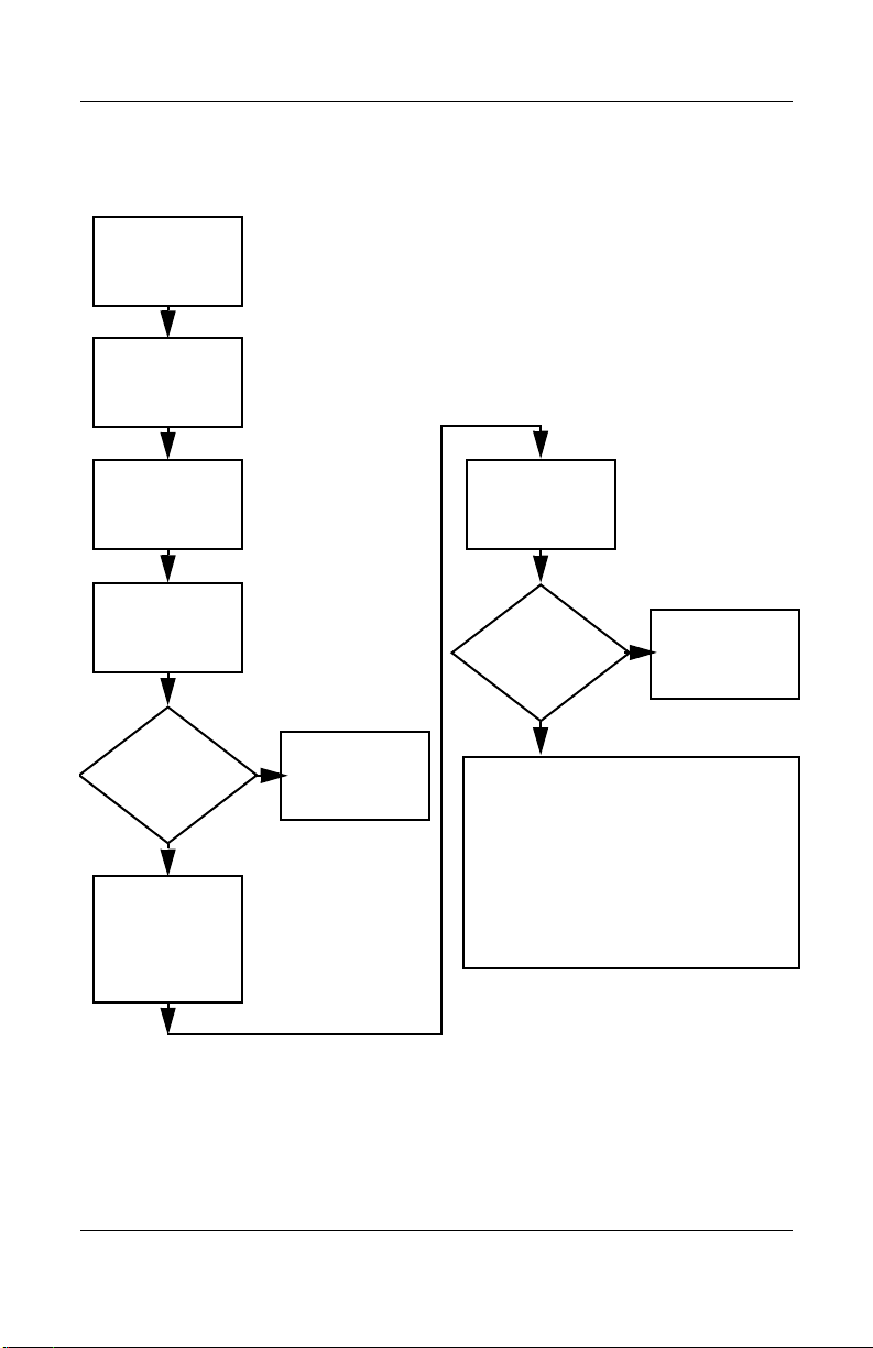
Flowchart 2.9—No Operating System (OS) Loading
No OS
loading.*
Reseat power
cord in expansion
base and
power outlet.
No OS loading from hard drive,
go to Flowchart 2.10,
No OS Loading, Hard Drive, Part 1.
No OS loading from diskette drive,
go to Flowchart 2.13,
No OS Loading, Diskette Drive.
No OS loading from CD- or DVD-ROM drive,
No OS Loading, CD- or DVD-ROM Drive.
*NOTE: Before beginning troubleshooting,
always check cable connections, cable ends,
and drives for bent or damaged pins.
Maintenance and Service Guide 2–19
go to Flowchart 2.14,
No OS loading from network,
go to Flowchart 2.20,
No Network/Modem Connection.
Page 44

Troubleshooting
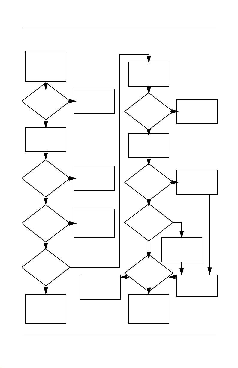
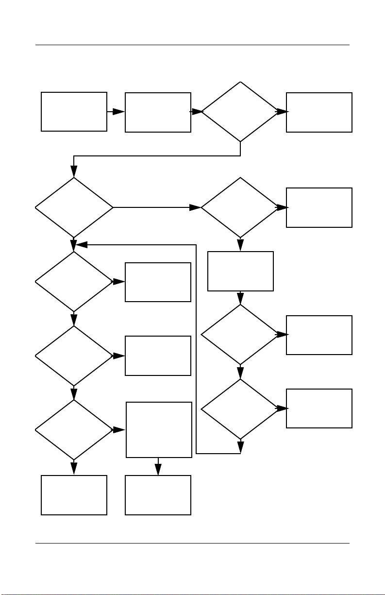
Flowchart 2.10—No OS Loading, Hard Drive, Part 1
OS not
loading from
hard drive.
Nonsystem
disk message?
N
Reseat
external
hard drive.
OS loading?
N
Boot
from
CD?
Y
Check the Setup
utility for correct
booting order.
Y
Go to
Flowchart 2.11,
No OS Loading
from Hard Drive,
Part 2.
Y
Done
N
N
Boot
from
diskette?
Y
Go to
Flowchart 2.13,
No OS
Loading from
Diskette Drive.
N
Boot
from
hard drive?
Y
Done
Change boot
priority through
the Setup utility
and reboot.
Boot
from
hard drive?
N
Go to
Flowchart 2.17,
Nonfunctioning
Device.
Y
2–20 Maintenance and Service Guide
Page 45
Troubleshooting
Flowchart 2.11—No OS Loading, Hard Drive, Part 2
Continued from
Flowchart 2.10,
No OS Loading
from Hard Drive,
Part 1.
CD or
diskette in
drive?
Y
Remove
diskette and
reboot.
N
1. Replace hard
drive.
2. Replace system
board.
hard drive.
accessible?
N
Run FDISK.
Reseat
Hard drive
Y
Done
Boot
from
hard drive?
N
Boot
from diskette
drive?
Y
Hard drive
accessible?
Y
Go to
Flowchart 2.12,
No OS Loading
from Hard Drive,
Part 3.
Y
N
Flowchart 2.13,
No OS Loading
N
Done
Go to
from Diskette
Drive.
Done
Hard drive
partitioned?
Y
Hard drive
formatted?
Y
Y
Notebook
booted?
Go to
Flowchart 2.12,
No OS Loading
from Hard Drive,
Part 3.
N
Create partition,
then format hard
drive to bootable
C:\ prompt.
N
Format hard drive
and bring to
a bootable
C:\ prompt.
Load OS using
System Restore
CD
N
(if applicable).
Maintenance and Service Guide 2–21
Page 46
Troubleshooting
Flowchart 2.12—No OS Loading, Hard Drive, Part 3
Continued from
Flowchart 2.11,
No OS Loading
from Hard Drive,
Part 2.
N
System
files on hard
drive?
Y
Virus
on hard
drive?
N
Run SCANDISK
and check for
bad sectors.
Can bad
sectors
be fixed?
Y
Fix bad
sectors.
Install OS
and reboot.
Y
Clean virus.
OS
loading from
hard drive?
Y
Done
N
Y
Diagnostics
on diskette?
Replace
hard drive.
N
N
Replace
hard drive.
Run diagnostics
and follow
recommendations.
N
Boot from
hard drive?
Replace
hard drive.
Y
Done
2–22 Maintenance and Service Guide
Page 47
Troubleshooting
Y
Flowchart 2.13—No OS Loading, Diskette Drive
OS not loading
from
diskette drive.
Nonsystem
disk message?
Boot
from another
device?
Y
Diskette
drive enabled
in the Setup
utility?
Y
Y
N
N
Reseat
diskette drive.
Go to
Flowchart 2.17,
Nonfunctioning
Device.
Enable drive
and cold boot
notebook.
OS
loading?
N
Bootable
diskette
in drive?
YN
Check diskette
for system files.
Try different
diskette.
Nonsystem
disk error?
N
Done
N
Install bootable
diskette and
reboot notebook.
Y
1. Replace
diskette drive.
2. Replace system
board.
Y
Y
Is diskette
drive boot
order
correct?
N
Change boot
priority using
the Setup utility.
Maintenance and Service Guide 2–23
Clear CMOS.
Refer to
Section 1.2,
“Clearing a
Password,” for
instructions.
Go to
Flowchart 2.17,
Nonfunctioning
Device.
N
OS
loading?
Done
Page 48

Troubleshooting
Y
N
Flowchart 2.14—No OS Loading, CD- or
DVD-ROM Drive
No OS
loading from
CD- or
DVD-ROM Drive.
Boots from
CD or DVD?
N
Reseat
drive.
N
Y
N
Y
Disc
in drive?
Install
bootable disc.
Done
Boots from
CD or DVD?
Booting
from another
device?
Y
Y
N
Bootable
disc in
drive?
Try another
bootable disc.
Done
Go to
Flowchart 2.17,
Nonfunctioning
Device.
Install bootable
disc and
reboot
notebook.
Clear CMOS.
Y
Booting
order
correct?
N
Correct boot
order using
the Setup utility.
2–24 Maintenance and Service Guide
Refer to
Section 1.2,
“Clearing a
Password,” for
instructions.
Go to
Flowchart 2.17,
Nonfunctioning
Device.
Page 49

Flowchart 2.15—No Audio, Part 1
Y
Turn up audio
No audio.
internally or
externally.
Audio? Done
N
Troubleshooting
Notebook in
expansion base
(if applicable)?
N
Go to
Flowchart 2.16,
No Audio, Part 2.
Y
Undock
Replace the following expansion base
components one at a time, as applicable.
Check audio status after each change.
1. Reseat expansion base audio cable.
2. Replace audio cable.
3. Replace speaker.
4. Replace expansion base audio board.
5. Replace backplane board.
6. Replace I/O board.
Go to
Flowchart 2.17,
Nonfunctioning
Device.
N
Internal
audio?
Y
Y
Audio? Done
N
Go to
Flowchart 2.16,
No Audio, Part 2.
Maintenance and Service Guide 2–25
Page 50

Troubleshooting
Flowchart 2.16—No Audio, Part 2
Continued from
Flowchart 2.15,
No Audio, Part 1.
N
Audio
driver in OS
configured?
Reload
audio drivers.
Y
N
Correct
drivers for
application?
Load drivers and
set configuration
in OS.
Y
Connect to
external
speaker.
Replace audio
board and
Audio?
YN
speaker
connections
in notebook
(if applicable).
1. Replace internal speakers.
2. Replace audio board (if applicable).
3. Replace system board.
Audio? Done
YN
2–26 Maintenance and Service Guide
Page 51

Flowchart 2.17—Nonfunctioning Device
Nonfunctioning
device.
Reseat
device.
Unplug the nonfunctioning device from
the notebook and inspect cables and plugs for
bent or broken pins or other damage.
Y
Clear
CMOS.
Any physical
device detected?
N
Troubleshooting
Fix or
replace
broken item.
Reattach device.
Close notebook,
plug in power,
and reboot.
Replace hard
drive.
Go to
Flowchart 2.9,
No OS Loading.
N
Device
boots
properly?
Replace NIC.
If integrated NIC,
replace system
board.
Y
Done
Maintenance and Service Guide 2–27
Replace diskette
drive.
Device
boots
properly?
Y
Done
N
Page 52
Troubleshooting
Flowchart 2.18—Nonfunctioning Keyboard
Keyboard
not operating
properly.
Connect notebook
to good external
keyboard.
N
External
device
works?
Replace
system
board.
Y
Reseat internal
keyboard
connector
(if applicable).
N
OK?
Replace internal
keyboard or
cable.
Y
Y
Done Done
OK?
N
Replace
system
board.
2–28 Maintenance and Service Guide
Page 53

Troubleshooting
Flowchart 2.19—Nonfunctioning Pointing Device
Pointing device
not operating
properly.
Connect notebook
to good external
pointing device.
N
External
device
works?
Replace
system
board.
Y
Reseat internal
pointing device
connector
(if applicable).
N
OK?
Replace internal
pointing device
or cable.
Y
Y
Done Done
OK?
N
Replace
system
board.
Maintenance and Service Guide 2–29
Page 54

Troubleshooting
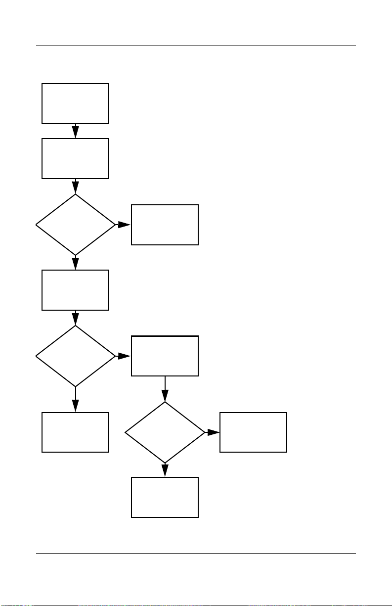
Flowchart 2.20—No Network/Modem Connection
No network
or modem
connection.
N
Network
or modem
jack active?
Y
Replace jack
or have jack
activated.
Y
Digital
line?
N
NIC/modem
configured
in OS?
Y
Disconnect all
power from
the notebook
and open.
Reseat
NIC/modem
(if applicable).
N
Connect
to nondigital
line.
Reload
drivers and
reconfigure.
N
Replace
NIC/modem
(if applicable).
N
Replace
system
Y
OK?
Done
Y
OK? Done
board.
2–30 Maintenance and Service Guide
Page 55

Illustrated Parts Catalog
This chapter provides an illustrated parts breakdown and a
reference for spare part numbers and option part numbers.
3.1 Serial Number Location
When ordering parts or requesting information, provide the
notebook serial number and model number located on the bottom
of the notebook.
3
Serial Number Location
Maintenance and Service Guide 3–1
Page 56
Illustrated Parts Catalog
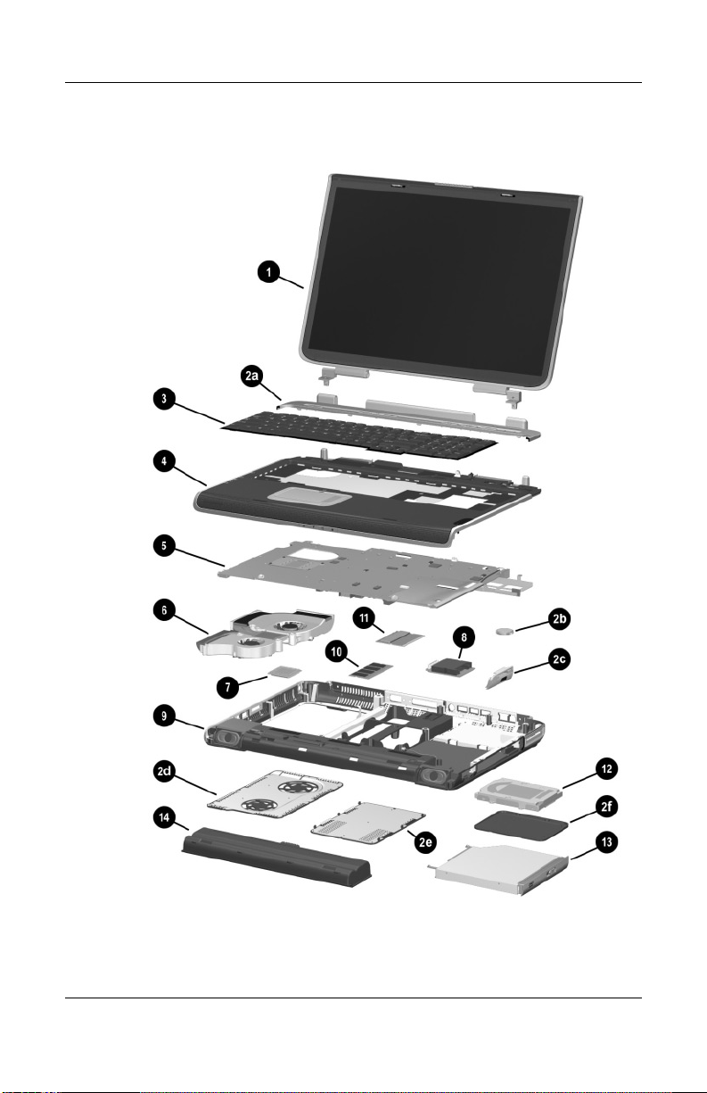
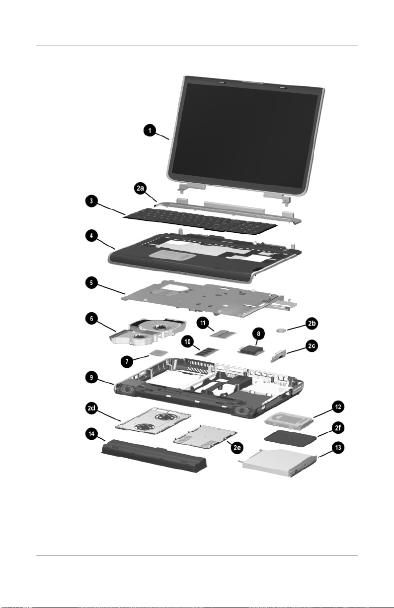
3.2 Notebook Major Components
Notebook Major Components
3–2 Maintenance and Service Guide
Page 57

Spare Parts: Notebook Major Components
Item Description
1 Display assemblies
Illustrated Parts Catalog
Table 3 - 1
Spare Part
Number
17.0-inch, WXGA
15.4-inch, WXGA
Miscellaneous Plastics Kit, includes: 344852-001
2a
2b
2c
2d
2e
2f
3 Keyboards
4 Top cover 344876-001
5 System boards (include the following video controllers and
Keyboard cover
RTC battery
SD Card slot/infrared module bezel
Fan cover
Memory expansion/Mini PCI compartment cover
Hard drive cover
Notebook feet (not illustrated)
France
French
Canada
Germany
Italy
video memory)
NVIDIA GeForce FX Go5000 with
128-MB video memory
NVIDIA GeForce FX Go5000 with
64-MB video memory
NVIDIA GeForce 4 440 Go with
64-MB video memory
344898-051
344898-121
344898-041
344898-061
Spain
Switzerland
United Kingdom
United States and
Canada
344894-001
344893-001
344898-071
344898-111
344898-031
344898-001
344879-001
344878-001
344877-001
6 Heat sink (includes large and small fans and
thermal paste)
Thermal Paste Kit 346178-001
Maintenance and Service Guide 3–3
344872-001
Page 58

Illustrated Parts Catalog
Notebook Major Components
3–4 Maintenance and Service Guide
Page 59

Table 3 - 1
Spare Parts: Notebook Major Components
Item Description
7 Processors (includes thermal paste)
Intel Pentium 4 DT with Hyper-Threading
Technology FSB
3.2-GHz 344890-001
Intel Pentium 4 DT with 800-MHz FSB
3.2-GHz
3.0-GHz
2.8-GHz
Illustrated Parts Catalog
(Continued)
Spare Part
Number
344889-001
344888-001
344887-001
Intel Pentium 4 DT with 533-MHz FSB
3.06-GHz
2.8-GHz
2.66-GHz
Thermal Paste Kit 346178-001
8 SD Card slot/infrared module (includes cable) 344880-001
9 Base enclosure (includes right and left speakers) 344883-001
10 Memory expansion boards, 333-MHz
1024-MB DDR
512-MB DDR
256-MB DDR
11 Mini PCI communications boards
Mini PCI 802.11b wireless LAN
Mini PCI 802.11g wireless LAN
344886-001
344885-001
344884-001
324702-001
324701-001
324700-001
344864-001
344863-001
Maintenance and Service Guide 3–5
Page 60
Illustrated Parts Catalog
Notebook Major Components
3–6 Maintenance and Service Guide
Page 61

Table 3 - 1
Spare Parts: Notebook Major Components
Item Description
12 Hard drives
Illustrated Parts Catalog
(Continued)
Spare Part
Number
80-GB (5400-rpm)
80-GB (4200-rpm)
60-GB (5400-rpm)
60-GB (4200-rpm)
40-GB (4200-rpm)
13 Optical drives
8X Max DVD-ROM/CD-RW combination drive
8X Max DVD-ROM drive
24X Max DVD+RW drive
14 Battery pack, 12-cell, 14.8-volt 342661-001
Wireless LAN antennae (not illustrated) 344875-001
Miscellaneous Cable Kit (not illustrated), includes: 344851-001
SD Card slot/infrared module cable
Display cable
LED board cable
344858-001
344856-001
344857-001
344855-001
344854-001
344860-001
344859-001
344861-001
Maintenance and Service Guide 3–7
Page 62

Illustrated Parts Catalog
3.3 Miscellaneous Plastics Kit Components
Miscellaneous Plastics Kit Components
Table 3 - 2
Miscellaneous Plastics Kit Components
Spare Part Number 344852-001
Item Description
1 Keyboard cover
2Fan cover
3RTC battery
4 Memory expansion/Mini PCI compartment cover
5Feet (5)
6 Hard drive cover
7 SD Card slot/infrared module bezel
3–8 Maintenance and Service Guide
Page 63
Illustrated Parts Catalog
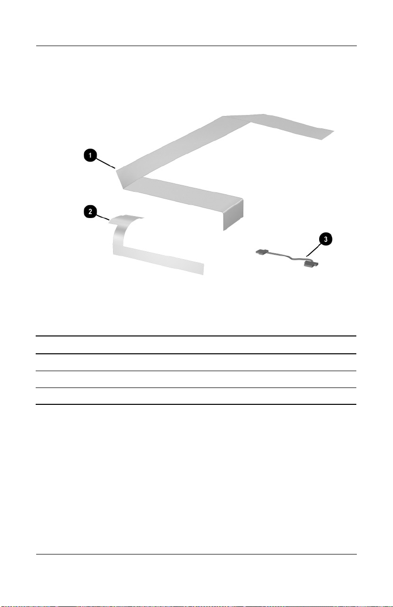
3.4 Miscellaneous Cable Kit Components
Miscellaneous Cable Kit Components
Table 3 - 3
Miscellaneous Cable Kit Components
Spare Part Number 344851-001
Item Description
1 SD Card slot/infrared module cable
2Display cable
3 LED board cable
Maintenance and Service Guide 3–9
Page 64

Illustrated Parts Catalog
3.5 Mass Storage Devices
Mass Storage Devices
Table 3-4
Mass Storage Devices
Spare Part Number Information
Item Description
Spare Part
Number
1 Hard drives (include hard drive bezel and frame)
80-GB (5400-rpm)
80-GB (4200-rpm)
60-GB (5400-rpm)
60-GB (4200-rpm)
40-GB (4200-rpm)
2 Optical drives
8X Max DVD-ROM/CD-RW combination drive
8X Max DVD-ROM drive
24X Max DVD+RW drive
USB v.1.1 diskette drive (not illustrated) 344897-001
3–10 Maintenance and Service Guide
344858-001
344856-001
344857-001
344855-001
344854-001
344860-001
344859-001
344861-001
Page 65

Illustrated Parts Catalog
3.6 Miscellaneous
Table 3-5
Spare Parts: Miscellaneous (not illustrated)
Description
Logo Kit 347990-001
120-watt AC adapter with power cord (for use in Canada,
French Canada, and United States)
135-watt AC adapter (for use in France, Germany, Italy,
Spain, Switzerland, and United Kingdom with the
following power cords)
Power cords (for use in the following countries with the 135 W AC adapter
listed above)
Fran ce
Germany
Italy
Spain
Switzerland
United Kingdom
Spare Part
Number
344895-001
346958-001
344895-051
344895-041
344895-061
344895-071
344895-111
344895-031
Screw Kit (includes the following screws; refer to
Appendix C, “Screw Listing,” for more information on
screw specifications and usage.)
■ PM2.5×8.0 screw
■ PM2.5×5.0 screw
■ PM2.5×4.0 screw
■ PM1.5×4.0 screw
Maintenance and Service Guide 3–11
■ Slotted M1.5×10.0 shoulder
screw
■ HM5.0×9.0 standoffs
■ PM1.5×12.0 spring-loaded
shoulder screw
344850-001
Page 66

Removal and Replacement
This chapter provides essential information for proper and safe
removal and replacement service.
4.1 Tools Required
You will need the following tools to complete the removal and
replacement procedures:
■ Magnetic screwdriver
■ Phillips P0 screwdriver
■ 5.0-mm socket for system board standoffs
■ Flat-bladed screwdriver
■ Tool kit (includes connector removal tool, loopback plugs,
and case utility tool)
4
Preliminaries
Maintenance and Service Guide 4–1
Page 67

Removal and Replacement Preliminaries
4.2 Service Considerations
The following sections include some of the considerations that
you should keep in mind during disassembly and assembly
procedures.
As you remove each subassembly from the notebook, place the
✎
subassembly (and all accompanying screws) away from the work
area to prevent damage.
Plastic Parts
Using excessive force during disassembly and reassembly can
damage plastic parts. Use care when handling the plastic parts.
Apply pressure only at the points designated in the maintenance
instructions.
Cables and Connectors
Cables must be handled with extreme care to avoid damage.
Apply only the tension required to unseat or seat the cables
during removal and insertion. Handle cables by the connector
whenever possible. In all cases, avoid bending, twisting, or
tearing cables. Ensure that cables are routed in such a way that
they cannot be caught or snagged by parts being removed or
replaced. Handle flex cables with extreme care; these cables
tear easily.
CAUTION: When servicing the notebook, ensure that cables are
Ä
placed in their proper locations during the reassembly process.
Improper cable placement can damage the notebook.
4–2 Maintenance and Service Guide
Page 68

Removal and Replacement Preliminaries
4.3 Preventing Damage to Removable Drives
Removable drives are fragile components that must be handled
with care. To prevent damage to the notebook, damage to a
removable drive, or loss of information, observe the following
precautions:
■ Before removing or inserting a hard drive, shut down the
notebook. If you are unsure whether the notebook is off or in
Hibernation, turn the notebook on, then shut it down.
■ Before removing a diskette drive or optical drive, ensure that
a diskette or disc is not in the drive. Ensure that the optical
drive tray is closed.
■ Before handling a drive, ensure that you are discharged of
static electricity. While handling a drive, avoid touching the
connector.
■ Handle drives on surfaces that have at least one inch of
shock-proof foam.
■ Avoid dropping drives from any height onto any surface.
■ After removing a hard drive, CD-ROM drive, or a diskette
drive, place it in a static-proof bag.
■ Avoid exposing a hard drive to products that have magnetic
fields, such as monitors or speakers.
■ Avoid exposing a drive to temperature extremes or liquids.
■ If a drive must be mailed, place the drive in a bubble pack
mailer or other suitable form of protective packaging and
label the package, “Fragile: Handle With Care.”
Maintenance and Service Guide 4–3
Page 69

Removal and Replacement Preliminaries
4.4 Preventing Electrostatic Damage
Many electronic components are sensitive to electrostatic
discharge (ESD). Circuitry design and structure determine the
degree of sensitivity. Networks built into many integrated circuits
provide some protection, but in many cases, the discharge
contains enough power to alter device parameters or melt silicon
junctions.
A sudden discharge of static electricity from a finger or other
conductor can destroy static-sensitive devices or microcircuitry.
Often the spark is neither felt nor heard, but damage occurs.
An electronic device exposed to electrostatic discharge might not
be affected at all and can work perfectly throughout a normal
cycle. Or the device might function normally for a while, then
degrade in the internal layers, reducing its life expectancy.
4.5 Packaging and Transporting Precautions
Use the following grounding precautions when packaging and
transporting equipment:
■ To avoid hand contact, transport products in static-safe
containers, such as tubes, bags, or boxes.
■ Protect all electrostatic-sensitive parts and assemblies with
conductive or approved containers or packaging.
■ Keep electrostatic-sensitive parts in their containers until the
parts arrive at static-free workstations.
■ Place items on a grounded surface before removing items
from their containers.
■ Always be properly grounded when touching a sensitive
component or assembly.
4–4 Maintenance and Service Guide
Page 70

Removal and Replacement Preliminaries
■ Store reusable electrostatic-sensitive parts from assemblies in
protective packaging or nonconductive foam.
■ Use transporters and conveyors made of antistatic belts and
roller bushings. Ensure that mechanized equipment used for
moving materials is wired to ground and that proper materials
are selected to avoid static charging. When grounding is not
possible, use an ionizer to dissipate electric charges.
4.6 Workstation Precautions
Use the following grounding precautions at workstations:
■ Cover the workstation with approved static-shielding material
(refer to Table 4-2).
■ Use a wrist strap connected to a properly grounded work
surface and use properly grounded tools and equipment.
■ Use conductive field service tools, such as cutters,
screwdrivers, and vacuums.
■ When using fixtures that must directly contact dissipative
surfaces, only use fixtures made of static-safe materials.
■ Keep the work area free of nonconductive materials, such as
ordinary plastic assembly aids and Styrofoam.
■ Handle electrostatic-sensitive components, parts, and
assemblies by the case or PCM laminate. Handle these items
only at static-free workstations.
■ Avoid contact with pins, leads, or circuitry.
■ Turn off power and input signals before inserting or removing
connectors or test equipment.
Maintenance and Service Guide 4–5
Page 71

Removal and Replacement Preliminaries
4.7 Grounding Equipment and Methods
Grounding equipment must include either a wrist strap or a foot
strap at a grounded workstation.
■ When seated, wear a wrist strap connected to a grounded
system. Wrist straps are flexible straps with a minimum of
one megohm ±10% resistance in the ground cords. To
provide proper ground, wear a strap snugly against the skin
at all times. On grounded mats with banana-plug connectors,
use alligator clips to connect a wrist strap.
■ When standing, use foot straps and a grounded floor mat.
Foot straps (heel, toe, or boot straps) can be used at standing
workstations and are compatible with most types of shoes
or boots. On conductive floors or dissipative floor mats, use
foot straps on both feet with a minimum of one megohm
resistance between the operator and ground. To be effective,
the conductive strips must be worn in contact with the skin.
Other grounding equipment recommended for use in preventing
electrostatic damage includes:
■ Antistatic tape
■ Antistatic smocks, aprons, and sleeve protectors
■ Conductive bins and other assembly or soldering aids
■ Nonconductive foam
■ Conductive tabletop workstations with ground cords of
one megohm resistance
■ Static-dissipative tables or floor mats with hard ties to
the ground
■ Field service kits
■ Static awareness labels
■ Material-handling packages
■ Nonconductive plastic bags, tubes, or boxes
4–6 Maintenance and Service Guide
Page 72

Removal and Replacement Preliminaries
■ Metal tote boxes
■ Electrostatic voltage levels and protective materials
Table 4-1 shows how humidity affects the electrostatic voltage
levels generated by different activities.
Table 4 - 1
Typical Electrostatic Voltage Levels
Relative Humidity
Event 10% 40% 55%
Walking across carpet 35,000 V 15,000 V 7,500 V
Walking across vinyl floor 12,000 V 5,000 V 3,000 V
Motions of bench worker 6,000 V 800 V 400 V
Removing DIPS from plastic tube 2,000 V 700 V 400 V
Removing DIPS from vinyl tray 11,500 V 4,000 V 2,000 V
Removing DIPS from Styrofoam 14,500 V 5,000 V 3,500 V
Removing bubble pack from PCB 26,500 V 20,000 V 7,000 V
Packing PCBs in foam-lined box 21,000 V 11,000 V 5,000 V
A product can be degraded by as little as 700 V.
✎
Table 4-2 lists the shielding protection provided by antistatic bags
and floor mats.
Table 4-2
Static-Shielding Materials
Material Use Voltage Protection Level
Antistatic plastic Bags 1,500 V
Carbon-loaded plastic Floor mats 7,500 V
Metallized laminate Floor mats 5,000 V
Maintenance and Service Guide 4–7
Page 73

5
Removal and Replacement
Procedures
This chapter provides removal and replacement procedures.
There are 66 screws and standoffs, in seven different sizes, that
must be removed, replaced, and loosened when servicing the
notebook. Make special note of each screw size and location
during removal and replacement.
Refer to Appendix C, “Screw Listing,” for detailed information
on screw sizes, locations, and usage.
Maintenance and Service Guide 5–1
Page 74

Removal and Replacement Procedures
5.1 Serial Number
Report the notebook serial number to HP when requesting
information or ordering spare parts. The serial number is located
on the bottom of the notebook.
Serial Number Location
5–2 Maintenance and Service Guide
Page 75

Removal and Replacement Procedures
5.2 Disassembly Sequence Chart
Use the chart below to determine the section number to be
referenced when removing notebook components.
Disassembly Sequence Chart
# of Screws
Section Description
5.3 Preparing the notebook for disassembly
Removed
Battery pack
Hard drive
5.4 Notebook feet 0
5.5 Memory expansion board 2 loosened
5.6 Mini PCI communications board 2 loosened
5.7 Optical drive 2
5.8 Keyboard 8 loosened on fan
5.9 Keyboard cover 6
5.10 Display assembly 4
5.11 Top cover 13
5.12 System board 5 screws,
5.13 RTC battery 0
5.14 Heat sink
Fans
5.15 Processor 0
5.16 SD Card slot/infrared module 3
5.17 Speakers 3
0
4 loosened
cover,
2 removed for keyboard
4 standoffs
4 loosened
6 removed
Maintenance and Service Guide 5–3
Page 76
Removal and Replacement Procedures
5.3 Preparing the Notebook for Disassembly
Perform the following steps before disassembling the notebook:
1. Turn off the notebook.
2. Disconnect the AC adapter and all external devices.
Spare Part Number Information
Battery pack, 12-cell, 14.8-volt 342661-001
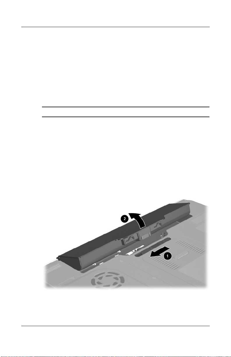
3. Remove the battery pack by following these steps:
a. Turn the notebook upside down with the rear panel
facing you.
b. Slide and hold the battery release latch 1 to the left. The
rear edge of the battery pack releases from the notebook.
c. Lift the rear edge of the battery pack up and swing it
forward 2.
d. Remove the battery pack.
Removing the Battery Pack
Reverse the above procedure to install the battery pack.
5–4 Maintenance and Service Guide
Page 77

Hard drives
Removal and Replacement Procedures
Spare Part Number Information
80-GB (5400-rpm)
80-GB (4200-rpm)
60-GB (5400-rpm)
60-GB (4200-rpm)
40-GB (4200-rpm)
4. Remove the hard drive by following these steps:
a. Turn the notebook upside down with the rear panel
facing you.
b. Loosen the four PM2.5×4.0 screws 1 that secure the hard
drive cover to the notebook.
c. Lift the cover straight up 2 to remove it from the
notebook.
The hard drive cover is included in the Miscellaneous Plastics
✎
Kit, spare part number 344852-001.
344858-001
344856-001
344857-001
344855-001
344854-001
Removing the Hard Drive Cover
Maintenance and Service Guide 5–5
Page 78

Removal and Replacement Procedures
d. Use the Mylar tab 1 to slide the hard drive to the right 2
to disconnect it from the system board.
e. Lift the hard drive straight up 3.
f. Remove the hard drive.
Removing the Hard Drive
Reverse the above procedure to install the hard drive.
5–6 Maintenance and Service Guide
Page 79

5.4 Notebook Feet
The notebook feet are adhesive-backed rubber pads. The feet are
included in the Miscellaneous Plastics Kit, spare part number
344852-001. The feet attach to the base enclosure as illustrated
below.
Replacing the Notebook Feet
Removal and Replacement Procedures
Maintenance and Service Guide 5–7
Page 80
Removal and Replacement Procedures
5.5 Memory Expansion Board
Spare Part Number Information
1024-MB DDR, 333-MHz
512-MB DDR, 333-MHz
256-MB DDR, 333-MHz
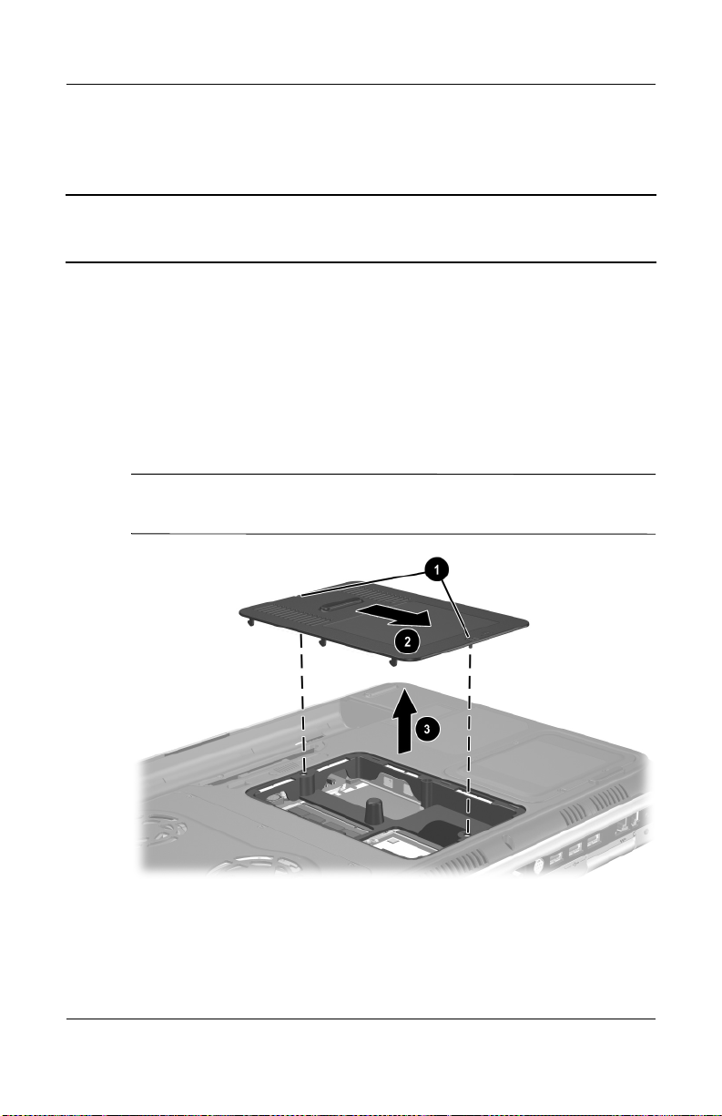
1. Prepare the notebook for disassembly (refer to Section 5.3).
2. Turn the notebook upside down with the rear panel
facing you.
3. Loosen the two PM2.5×4.0 screws 1 that secure the memory
expansion/Mini PCI compartment cover to the notebook.
4. Slide the cover forward 2, then lift the cover up 3.
5. Remove the cover.
The memory expansion/Mini PCI compartment cover is included
✎
in the Miscellaneous Plastics Kit, spare part number 344852-001.
324702-001
324701-001
324700-001
Removing the Memory Expansion/Mini PCI Compartment Cover
5–8 Maintenance and Service Guide
Page 81

Removal and Replacement Procedures
6. Spread the retaining tabs 1 that secure the memory
expansion board to the socket. The board rises up.
7. Pull the board away from the socket at a 45-degree angle 2.
Removing a Memory Expansion Board
Reverse the above procedure to install a memory expansion
board.
Maintenance and Service Guide 5–9
Page 82

Removal and Replacement Procedures
5.6 Mini PCI Communications Board
Spare Part Number Information
Mini PCI 802.11b wireless LAN
Mini PCI 802.11g wireless LAN
1. Prepare the notebook for disassembly (Section 5.3).
2. Remove the memory expansion/Mini PCI communications
compartment cover (Section 5.5).
3. Disconnect the two antenna cables 1 and 2 from the Mini
PCI communications board.
4. Spread the retaining tabs 3 that secure the Mini PCI
communications board to the socket. The board rises up.
5. Pull the board away from the socket at a 45-degree angle 4.
344864-001
344863-001
Removing a Mini PCI Communications Board
Reverse the above procedure to install a Mini PCI
communications board.
5–10 Maintenance and Service Guide
Page 83
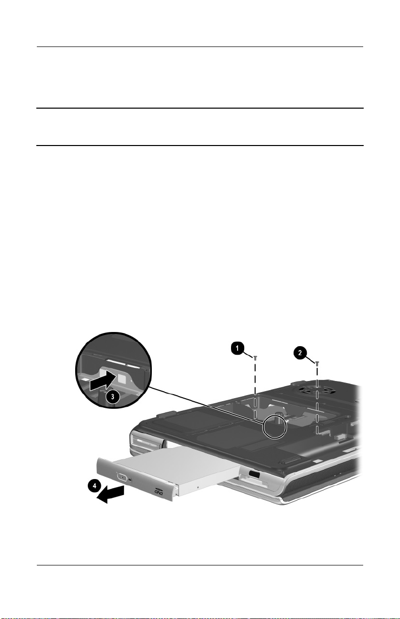
5.7 Optical Drive
Spare Part Number Information
8X Max DVD-ROM/CD-RW combination drive
8X Max DVD-ROM drive
24X Max DVD+RW drive
1. Prepare the notebook for disassembly (Section 5.3).
2. Remove the memory expansion/Mini PCI compartment cover
(Section 5.5).
3. Position the notebook so the front panel faces you.
4. Remove the PM2.5×5.0 screw 1 that secures the optical
drive in the memory expansion/Mini PCI compartment.
5. Remove the PM2.5×8.0 screw 2 that secures the optical
drive in the battery bay.
6. Push on the back of the optical drive 3 through the opening
on the left side of the memory expansion/Mini PCI
compartment.
7. Remove the optical drive 4.
Removal and Replacement Procedures
344860-001
344859-001
344861-001
Removing the Optical Drive
Reverse the above procedure to install an optical drive.
Maintenance and Service Guide 5–11
Page 84

Removal and Replacement Procedures
5.8 Keyboard
Spare Part Number Information
Fran ce
French Canada
Germany
Italy
1. Prepare the notebook for disassembly (Section 5.3).
2. Remove the memory expansion/Mini PCI compartment cover
(Section 5.5).
3. Turn the notebook upside down with the rear panel
facing you.
4. Loosen the eight PM2.5×5.0 screws 1 that secure the fan
cover to the notebook.
5. Remove the fan cover 2.
The fan cover is included in the Miscellaneous Plastics Kit,
✎
spare part number 344852-001.
344898-051
344898-121
344898-041
344898-061
Spain
Switzerland
United Kingdom
United States and
Canada
344898-071
344898-111
344898-031
344898-001
Removing the Fan Cover
5–12 Maintenance and Service Guide
Page 85

Removal and Replacement Procedures
6. Position the notebook so the front panel faces you.
7. Remove the PM2.5×8.0 screw 1 that secures the keyboard in
the memory expansion/Mini PCI compartment.
8. Remove the PM2.5×5.0 screw 2 that secures the keyboard in
the fan compartment.
Removing the Keyboard Screws
Maintenance and Service Guide 5–13
Page 86

Removal and Replacement Procedures
9. Turn the notebook right-side up with the front facing you.
10. Open the computer.
11. Use a flat-bladed tool to pry forward on the four keyboard
retaining tabs. The tabs are located above the
above the
the
f6 and f7 keys, above the f11 and f12 keys, and above
end and pg up keys.
f1 and f2 keys,
Releasing the Keyboard
5–14 Maintenance and Service Guide
Page 87

Removal and Replacement Procedures
12. Lift up on the back of the keyboard and swing it forward 1
until it rests on the palm rest.
13. Release the zero insertion force (ZIF) connector 2 to which
the keyboard cable is connected and disconnect the cable 3.
14. Remove the keyboard.
Removing the Keyboard
Reverse the above procedure to install the keyboard.
Maintenance and Service Guide 5–15
Page 88

Removal and Replacement Procedures
5.9 Keyboard Cover
The keyboard cover is included in the Miscellaneous Plastics Kit,
✎
spare part number 344852-001.
1. Prepare the notebook for disassembly (Section 5.3).
2. Remove the keyboard (Section 5.8).
3. Turn the notebook upside down with the rear panel
facing you.
4. Remove the four PM2.5×8.0 screws 1 that secure the
keyboard cover to the notebook.
5. Remove the two PM2.5×8.0 screws 2 that secure the
keyboard cover to the notebook through the rear panel.
Removing the Keyboard Cover Screws
5–16 Maintenance and Service Guide
Page 89

Removal and Replacement Procedures
6. Turn the notebook right-side up with the front facing you.
7. Open the notebook as far as it will open.
8. Lift up on the left and right sides 1 of the keyboard cover to
detach it from the notebook.
9. Lift the keyboard cover up and swing it forward 2 to
remove it.
Removing the Keyboard Cover
Reverse the above procedure to install the keyboard cover.
Maintenance and Service Guide 5–17
Page 90

Removal and Replacement Procedures
5.10 Display Assembly
Spare Part Number Information
17.0-inch, WXGA
15.4-inch, WXGA
1. Prepare the notebook for disassembly (Section 5.3).
2. Remove the keyboard (Section 5.8).
3. Remove the keyboard cover (Section 5.9).
4. Disconnect the display cable 1 and remove it from the
retaining clip 2 in the top cover.
5. Remove the two antenna cables from the hole and routing
channel in the top cover 3.
6. Remove the two PM2.5×8.0 screws 4 that secure the display
assembly to the notebook.
344894-001
344893-001
Removing the Display Assembly Screws
5–18 Maintenance and Service Guide
Page 91

Removal and Replacement Procedures
7. Position the notebook so the rear panel faces you and the
display is in an upright position.
8. Remove the two PM2.5×8.0 screws 1 that secure the display
assembly to the notebook through the rear panel.
9. Lift the display assembly straight up 2 to remove it.
Removing the Display Assembly
Reverse the above procedure to install the display assembly.
Maintenance and Service Guide 5–19
Page 92
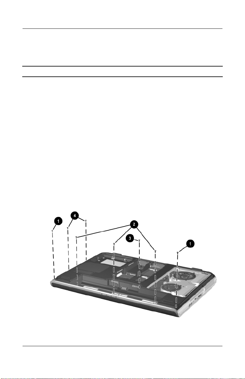
Removal and Replacement Procedures
5.11 Top Cover
Spare Part Number Information
Top cover 344876-001
1. Prepare the notebook for disassembly (Section 5.3) and
remove the following components:
❏ Optical drive (Section 5.7)
❏ Keyboard (Section 5.8)
❏ Keyboard cover (Section 5.9)
❏ Display assembly (Section 5.10)
2. Turn the notebook upside down with the front facing you.
3. Remove the following:
1 Two PM2.5×8.0 screws on the notebook front edge
2 Three PM2.5×5.0 screws in the battery bay
3 One PM2.5×8.0 screw in the rear/right corner of the
battery bay
4 Two PM2.5×5.0 screws in the optical drive bay
Removing the Top Cover Screws
5–20 Maintenance and Service Guide
Page 93
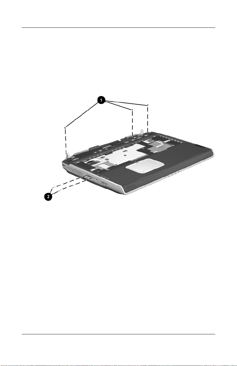
Removal and Replacement Procedures
4. Turn the notebook right-side up with the front facing you.
5. Remove the three PM2.5×8.0 screws 1 that secure the top
cover to the notebook.
6. Remove the two slotted M1.5×10.0 shoulder screws 2 that
secure the top cover to the notebook on each side of the
docking connector.
Removing the Top Cover Screws (continued)
Maintenance and Service Guide 5–21
Page 94

Removal and Replacement Procedures
7. Disconnect the LED board cable 1 from the system board
and remove the cable from the clip in the top cover.
The LED board cable is included in the Miscellaneous Cable Kit,
✎
spare part number 344851-001. The LED board is included with
the top cover.
8. Disconnect the display lid switch module cable 2 from the
display lid switch module.
9. Lift the front edge of the top cover 3 until the TouchPad
cable 4 is accessible.
10. Disconnect the TouchPad cable from the low insertion force
(LIF) connector on the system board.
11. Remove the top cover 5.
Removing the Top Cover
Reverse the above procedure to install the top cover.
5–22 Maintenance and Service Guide
Page 95

Removal and Replacement Procedures
5.12 System Board
Spare Part Number Information
NVIDIA GeForce FX Go5000 with 128-MB video memory
NVIDIA GeForce FX Go5000 with 64-MB video memory
NVIDIA GeForce 4 440 Go with 64-MB video memory
When replacing the system board, ensure that the following
✎
components are removed from the defective system board and
installed on the replacement system board:
■ Memory expansion boards (Section 5.5)
■ Mini PCI communications board (Section 5.6)
■ Real time clock battery (Section 5.13)
■ Heat sink (Section 5.14)
■ Processor (Section 5.15)
1. Prepare the notebook for disassembly (Section 5.3) and
remove the following components:
344879-001
344878-001
344877-001
❏ Optical drive (Section 5.7)
❏ Keyboard (Section 5.8)
❏ Keyboard cover (Section 5.9)
❏ Display assembly (Section 5.10)
❏ Top cover (Section 5.11)
Maintenance and Service Guide 5–23
Page 96

Removal and Replacement Procedures
2. Release the ZIF connector 1 to which the SD Card
slot/infrared module cable is attached and disconnect the
cable 2.
3. Disconnect the right 3 and left 4 speaker cables from the
system board.
Disconnecting the SD Card Slot/Infrared Module and Speaker
Cables from the System Board
5–24 Maintenance and Service Guide
Page 97

Removal and Replacement Procedures
4. Position the notebook so the rear panel faces you.
5. Remove the six PM2.5×8.0 screws 1 that secure the system
board to the notebook.
6. Use a 5.0-mm socket to remove the four HM5.0×9.0
standoffs 2 that secure the system board to the notebook on
each side of the parallel and external monitor connectors.
Removing the System Board Screws and Standoffs
Maintenance and Service Guide 5–25
Page 98
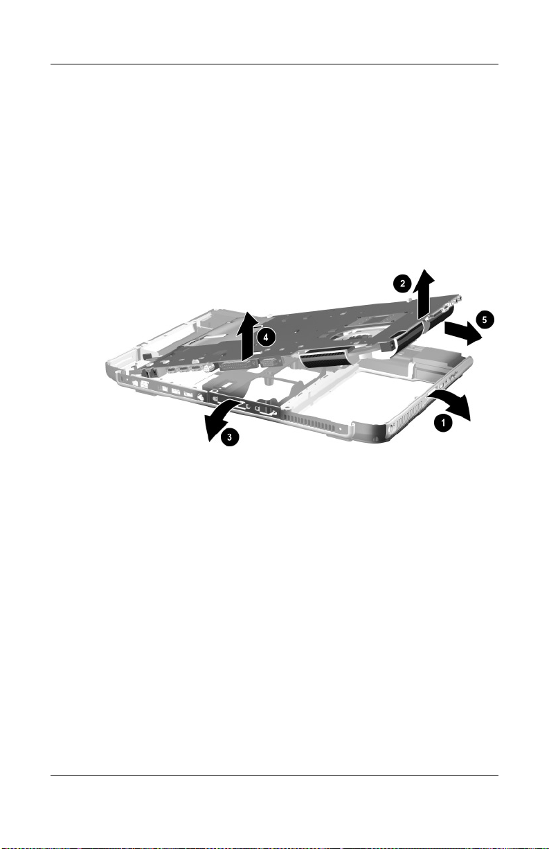
Removal and Replacement Procedures
7. Flex the right side of the base enclosure to the right 1.
8. Lift the right side of the system board 2 until the connectors
on the right side of the board clear the base enclosure.
9. Flex the rear edge of the system board toward you 3.
10. Lift the rear edge of the system board 4 until the connectors
on the rear panel of the board clear the base enclosure.
11. Slide the system board to the right at an angle 5 and
remove it.
Removing the System Board
Reverse the above procedure to install the system board.
5–26 Maintenance and Service Guide
Page 99

5.13 RTC Battery
The RTC battery is included in the Miscellaneous Plastics Kit,
✎
spare part number 344852-001.
1. Prepare the notebook for disassembly (Section 5.3) and
remove the following components:
❏ Optical drive (Section 5.7)
❏ Keyboard (Section 5.8)
❏ Keyboard cover (Section 5.9)
❏ Display assembly (Section 5.10)
❏ Top cover (Section 5.11)
❏ System board (Section 5.12)
2. Turn the system board upside down with the rear panel
facing you.
3. Remove the RTC battery from the socket.
Removal and Replacement Procedures
Removing the RTC Battery
Reverse the above procedure to install the RTC battery.
Maintenance and Service Guide 5–27
Page 100

Removal and Replacement Procedures
5.14 Heat Sink
Spare Part Number Information
Heat sink (includes large and small fans and thermal paste) 344872-001
Thermal Paste Kit 346178-001
1. Prepare the notebook for disassembly (Section 5.3) and
remove the following components:
❏ Optical drive (Section 5.7)
❏ Keyboard (Section 5.8)
❏ Keyboard cover (Section 5.9)
❏ Display assembly (Section 5.10)
❏ Top cover (Section 5.11)
❏ System board (Section 5.12)
2. Turn the system board upside down with the rear panel
facing you.
5–28 Maintenance and Service Guide
 Loading...