

Page 1

HP NJ5000-5G-PoE+ Walljack Switch
Getting Started Guide
Part number: 5998-7331
Document version: 5W100-20150430
Page 2

Legal and notice information
© Copyright 2015 Hewlett-Packard Development Company, L.P.
No part of this documentation may be reproduced or transmitted in any form or by any means without
prior written consent of Hewlett-Packard Development Company, L.P.
The information contained herein is subject to change without notice.
HEWLETT-PACKARD COMPANY MAKES NO WARRANTY OF ANY KIND WITH REGARD TO THIS
MATERIAL, INCLUDING, BUT NOT LIMITED TO, THE IMPLIED WARRANTIES OF MERCHANTABILITY
AND FITNESS FOR A PARTICULAR PURPOSE. Hewlett-Packard shall not be liable for errors contained
herein or for incidental or consequential damages in connection with the furnishing, performance, or use
of this material.
The only warranties for HP products and services are set forth in the express warranty statements
accompanying such products and services. Nothing herein should be construed as constituting an
additional warranty. HP shall not be liable for technical or editorial errors or omissions contained herein.
Page 3

i
Contents
Preparing for installation ················································································································································· 1
General safety recommendations ··································································································································· 1
Examining the installation site ········································································································································· 1
Accessories provided with the switch ····························································································································· 2
Installation preparation checklist ····································································································································· 2
Installing the Switch ························································································································································· 3
Installing the switch in an inwall ····································································································································· 3
Installing the switch on a wall ········································································································································· 6
Installing the switch on a horizontal surface ·················································································································· 9
Accessing the switch for the first time ························································································································· 10
Logging in to the CLI ······················································································································································ 10
Setting up configuration environment ·················································································································· 10
Connecting the console cable ······························································································································ 10
Setting terminal parameters ·································································································································· 11
Logging in to the Web interface for the first time ······························································································· 11
Setting the working mode ············································································································································ 13
Support and other resources ········································································································································ 14
Contacting HP ································································································································································· 14
Subscription service ··············································································································································· 14
Related information ························································································································································ 14
Documents ······························································································································································ 14
Websites ································································································································································· 14
Conventions ····································································································································································· 15
Appendix A Chassis views and technical specifications ·························································································· 17
Overview ········································································································································································· 17
Ports ·················································································································································································· 18
Reset button ···························································································································································· 18
Weights and dimensions ··············································································································································· 19
Power consumption ························································································································································ 19
Storage media and memory specifications ················································································································· 19
Power specifications ······················································································································································· 19
Appendix B LEDs ··························································································································································· 20
Page 4

1
Preparing for installation
IMPORTANT:
For regulatory identification purposes, the HP NJ5000-5G-PoE+
is assigned a regulatory model number
(RMN) HNGZA-HA0025. This regulatory number should not be confused with the marketing name HP
NJ5000-5G-PoE+, or product code JH237A.
The HP NJ5000-5G-PoE+ Walljack Switch is hereinafter referred to as the HP NJ5000-5G-PoE+.
General safety recommendations
To avoid possible bodily injury or equipment damage, read the following safety recommendations
before you install an HP NJ5000-5G-PoE+. The recommendations do not cover every possible
hazardous condition.
• Keep the chassis clean and dust-free.
• Make sure the ground is dry and flat and anti-slip measures are in place.
• Do not place the switch in a moist area and avoid liquid surrounding the switch.
• Keep the chassis and installation tools away from walkways.
Examining the installation site
The HP NJ5000-5G-PoE+ must be used indoors. To ensure correct operation and long service life of your
switch, install it in an environment that meets the requirements described in Table 1.
Table 1 Environmental specifications
Operating temperature
Relative humidity
0°C to 45°C (32°F to 113°F) 5% to 95%, noncondensing
Page 5
2
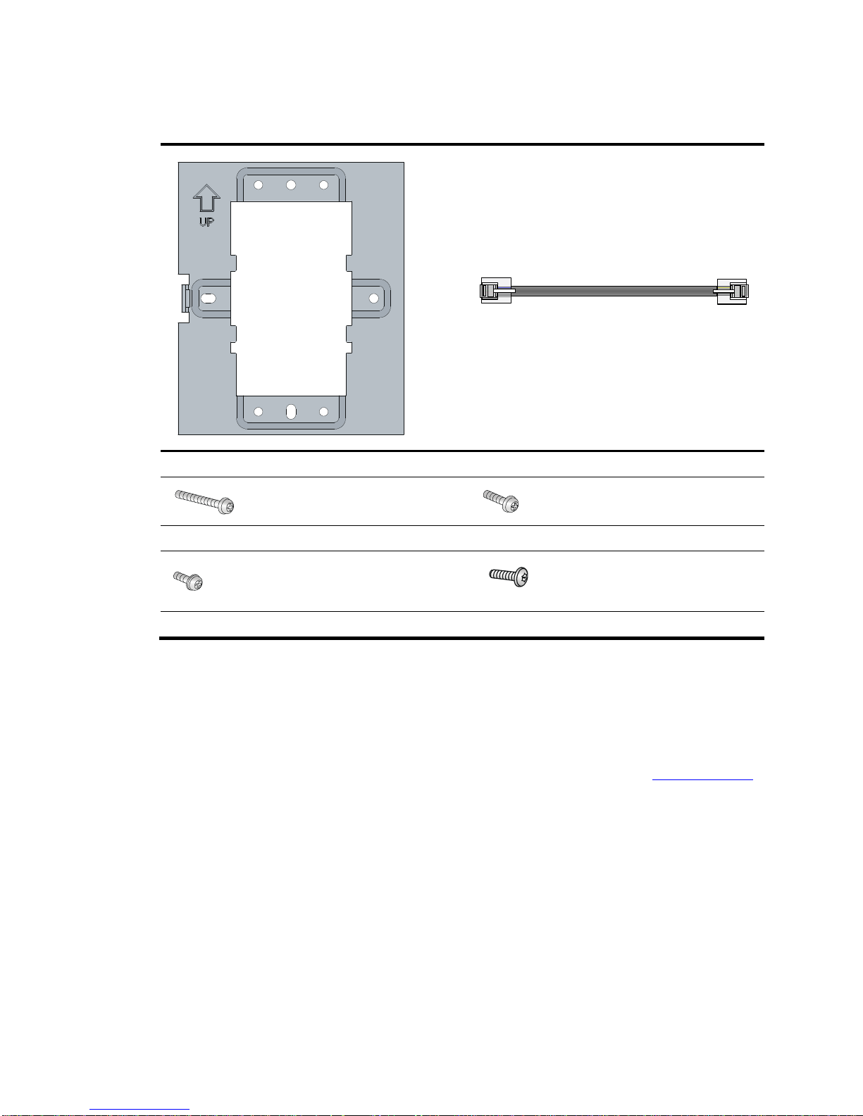
Accessories provided with the switch
× 1
× 1
Wall-mounting bracket Ethernet network cable
× 2
× 2
M3.5 × 25 Phillips-head screw(Length:25mm) M3.5 × 12 Phillips-head screw(Length:12mm)
× 1
× 1
M2.9 × 4 Phillips-head screw(Length:4mm) M2.9 × 4 security Torx-10 screw(Length:4mm)
Installation preparation checklist
Before you install the switch, verify the following items:
• Connect the power cord and connect the switch to the network. Examine the LED status to make sure
the switch can operate correctly. For more information about switch LEDs, see "Appendix B LEDs."
• Verify that cabling has been completed.
Page 6
3
Installing the Switch
The NJ5000-5G-PoE+ Walljack is designed to be mounted on a standard NEMA-WD6 (US) or BS 4662
(International)electrical outlet box.
You can also install the HP NJ5000-5G-PoE+ using the optional HP unified wired-WLAN walljack
table/flush wall mount kit (JL022A). This kit, which is purchased separately, lets you install the switch on
a horizontal surface or wall.
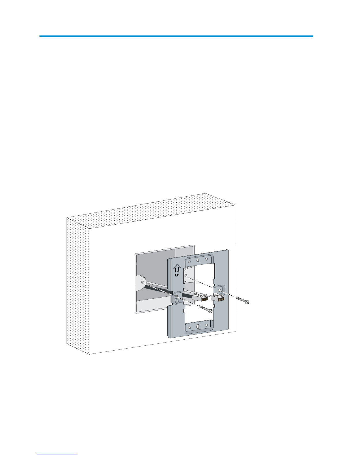
Installing the switch in an inwall
1. Place the mounting bracket, with the UP arrow pointing up, on the electrical outlet box, and then
use two of the supplied mounting screws to secure the bracket to the box.
The two M3.5 × 25 mounting screws are for a US electrical box. The two M3.5 × 12 mounting
screws are for an EU electrical outlet box.
Figure 1 Securing the mounting bracket to an electrical outlet box (EU)
Page 7
4
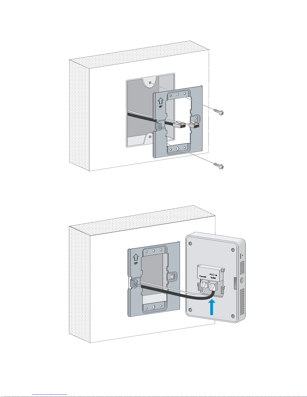
Figure 2 Securing the mounting bracket to an electrical outlet box (US)
2. Connect the network cable from the electrical outlet box to the RJ-45 uplink port on the back of the
HP NJ5000-5G-PoE+.
Figure 3 Connecting the network cable
3. Align the installation hole in the rear of the switch with the standout on the mounting bracket.
Page 8
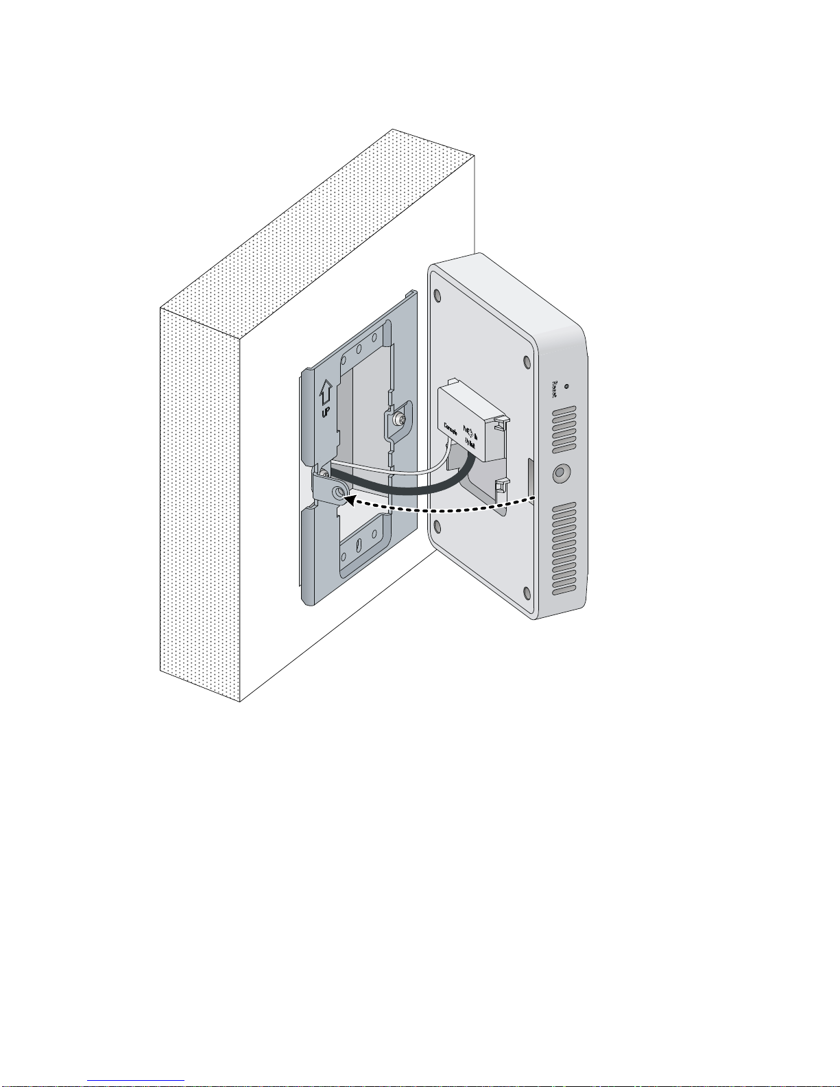
5
Figure 4 Aligning the installation hole
4. Push the HP NJ5000-5G-PoE+ onto the mounting bracket, and then slide it down until it is fully
engaged. Then secure the switch to the bracket by using the Phillips-head screw or security-head
security Torx-10 screw. Do not release the HP NJ5000-5G-PoE+ until you confirm that it is secured
in place.
Page 9

6
Figure 5 Securing the HP NJ5000-5G-PoE+
Installing the switch on a wall
Before installing the HP NJ5000-5G-PoE+ on a wall, make sure the surface of the wall can support a
minimum weight of 0.9 kg (2 lbs) and extra cables.
1. Hold the optional unified wired WLAN walljack table/flush wall mount panel in a vertical
orientation against the wall where it will be installed. Mark two holes for the screws or
user-supplied wall anchors.
2. Use the two supplied screws or user-supplied wall anchors to loosely attach the mount panel to the
wall. If using wall anchors, drill two holes, typically 4.7 mm (0.19 in) in diameter, and then insert
the anchors.
1
2
Page 10

7
Figure 6 Attaching the mount panel to the wall
3. Run the required network cable through the top, bottom, or side of the wall mount panel allowing
sufficient length for the cable to reach the not-yet installed HP NJ5000-5G-PoE+.
4. Tighten the screws or tap the wall anchors flush with the wall to secure the mount panel to the wall.
5. Place the mounting bracket, with the UP arrow pointing up, on the wall mount panel. Use four
mounting screws to secure the bracket to the panel.
Figure 7 Attaching the mounting bracket to the wall mount panel
6. Connect the network cable from the panel to the RJ-45 uplink port on the back of the HP
NJ5000-5G-PoE+.
HP Unified
WiredWLAN
Walljack
Table/Flush
Wall Mount
Kit
(JL022A)
Page 11

8
Figure 8 Connecting the network cable
7. Align the installation hole in the rear of the switch with the standout on the mounting bracket.
8. Push the HP NJ5000-5G-PoE+ onto the mounting bracket, and then slide it down until it is fully
engaged. Then secure the switch to the bracket by using the Phillips-head screws or security-head
security Torx-10 screws. Do not release the HP NJ5000-5G-PoE+ until you confirm that it is secured
in place.
Figure 9 Securing the HP NJ5000-5G-PoE+
1
2
Page 12

9
Installing the switch on a horizontal surface
CAUTION:
Be sure to install the units in an area that is well ventilated and maintains an ambient
temperature of less
than 45°C (113°F). Do not install in enclosed spaces or close to or directly above any heat sources or
heat-emitting devices. If the installation area has any obstructions to air
flow, you must take steps to ensure
adequate airflow is maintained. The ventilation slots must not
be blocked in any way. Ensure that there is
at least 15.25 cm (6 inches) of clearance from all vents.
1. Hold the optional Unified Wired WLAN Walljack Table/Flush Wall Mount panel on the desktop
where it will be installed. Mark two holes for the screws.
2. Use the supplied two screws to loosely attach the mount panel to the table.
3. Run the required network cables through the top, bottom, or sides of the mount panel allowing
sufficient length for the cables to reach the not-yet installed HP NJ5000-5G-PoE+.
4. Tighten the screws to secure the mount panel to the table.
5. Place the mounting bracket, on the mount panel, and then use four mounting screws to secure the
bracket to the panel.
6. Connect the network cable from the panel to the RJ-45 Uplink port on the back of the HP
NJ5000-5G-PoE+.
7. Push the HP NJ5000-5G-PoE+ onto the mounting bracket, then slide it down until it is fully engaged.
Do not release the HP NJ5000-5G-PoE+ until you confirm that it is securely in place.
8. Use the supplied small Phillips head bracket screw or Torx-10 security screw to secure the side of
the HP NJ5000-5G-PoE+ to the bracket.
9. Connect cables:
• Connect equipment that requires PoE to Port3 and 4.
• Connect other equipment to Ports 1, 2, 3, and 4.
Page 13

10
Accessing the switch for the first time
Logging in to the CLI
Setting up configuration environment
The first time you access the switch you must use a console cable (RJ-45 connector for console cable,user
supplied) to connect a configuration terminal, for example, a PC, to the console port on the switch, as
shown in Figure 10.
Figure 10 Connecting the console port to a terminal
Connecting the console cable
A console cable is an 8-core shielded cable, with a crimped RJ-45 connector at one end for connecting
to the console port of the switch, and a DB-9 female connector at the other end for connecting to the
serial port on the configuration terminal.
Figure 11 Console cable
Table 2 Console cable pinouts
RJ-45 Signal
DB-9
Signal
1 RTS 8 CTS
2 DTR 6 DSR
PoE Switch
PC
Main label
1
8
B side
B
Pos.9
Pos.1
A side
A
Page 14

11
RJ-45 Signal
DB-9
Signal
3 TXD 2 RXD
4 SG 5 SG
5 SG 5 SG
6 RXD 3 TXD
7 DSR 4 DTR
8 CTS 7 RTS
To connect a terminal (for example, a PC) to the switch:
1. Connect the DB-9 female connector of the console cable to the serial port of the PC.
2. Connect the RJ-45 connector to the console port of the switch.
NOTE:
• Identify the mark on the console port and make sure you are connecting to the correct port.
• The serial ports on PCs do not support hot swapping.To connect a PC to an operating switch, first
connect the PC end. To disconnect a PC from an operating switch, first disconnect the switch end.
• Purchase the console cable at HP Parts Store (http://partsurfer.hp.com/) using the part number
5184-6719. Note: the console cable (5184-6719) is supplied on many HP products.
Setting terminal parameters
Start a terminal application such as HyperTerminal on the computer. Configure the utility with the
following parameters:
Bits per second—38400
Data bits—8
Parity—None
Stop bits—1
Flow control—None
Emulation—VT100
Logging in to the Web interface for the first time
IMPORTANT:
For security purposes, HP recommends that you change the login information and assign access
permissions immediately after the first successful login.
By default, HTTP and HTTPS are enabled.
To log in to the Web interface:
1. Use an Ethernet cable to connect the configuration terminal to an Ethernet port on the device.
Page 15

12
2. Identify the IP address and mask of the device.
¡ If the device is not connected to the network, or no DHCP server exists on the network, the
device uses the default IP address and mask. The default mask is 255.255.0.0. The default IP
address is 169.254.xxx.xxx, where xxx.xxxdepends on the last two bytes of the MAC address.
Find the MAC address label on the device and use the following rules to determine the last two
bytes for the IP address:
Last two bytes of the
MAC address
Last two bytes for the IP address
All 0s 0.1
All Fs 255.1
Not all 0s or all Fs Decimal values of the last two bytes of the MAC address
For example:
MAC address
IP address
08004E080000 169.254.0.1
08004E08FFFF 169.254.255.1
08004E082A3F
169.254.42.63 (The decimal value of 2A is 42. The value
of 3F is 63.)
¡ If aDHCP server is available, the device obtains an IP address from the server. To identify the
address, log in to the device through the console port, and then execute the display ip interface
brief command. The following is the sample output:
<HP> display ip interface brief
*down: administratively down
(s): spoofing
Interface Physical Protocol IP Address Description
Vlan1 up up 169.254.54.32 Vlan-interface1
<HP>
For more information about console login, see the getting started guide for the device.
3. Assign the login host an IP address in the same subnet as the device.
4. Open the browser, and then enter login information:
a. In the address bar, enter the IP address of the device.
− HTTP access—Enter the address in thehttp://ip-address:portor ip-address:portformat.
− HTTPS access—Enter the address in thehttps://ip-address:portformat.
The ip-address argument represents the IP address of the device. The port argument represents
the HTTP or HTTPS service port. The default port number is 80 for HTTP and 443 for HTTPS.
You do not need to enter the port number if you have not changed the service port setting.
b. On the login page, enter the default username (admin) and the verification code.
You do not need to enter a password at the first login.
c. Click Login.
Page 16

13
Setting the working mode
The switch can operate in managed mode(the default) or unmanaged mode.
NOTE:
To change the
mode, connect to the console port of the switch and execute the following
commands at the CLI:
<HP> system-view
[HP] manage-mode on /* Managed mode */
[HP] undo manage-mode on /* Unmanaged mode */
• When the switch operates in unmanaged mode, you do not need to configure the switch.
• When the switch operates in managed mode, you can configure the switch at the CLI or the Web
interface. HP recommends that you use the Web interface. For more information about switch
configuration, see the user guide.
Page 17

14
Support and other resources
Contacting HP
For worldwide technical support information, see the HP support website:
http://www.hp.com/support
Before contacting HP, collect the following information:
• Product model names and numbers
• Technical support registration number (if applicable)
• Product serial numbers
• Error messages
• Operating system type and revision level
• Detailed questions
Subscription service
HP recommends that you register your product at the Subscriber's Choice for Business website:
http://www.hp.com/go/wwalerts
After registering, you will receive email notification of product enhancements, new driver versions,
firmware updates, and other product resources.
Related information
Documents
To find related documents, browse to the Manuals page of the HP Business Support Center website:
http://www.hp.com/support/manuals
• For related documentation, navigate to the Networking section, and select a networking category.
• For a complete list of acronyms and their definitions, see HP FlexNetwork Technology Acronyms.
Websites
• HP.com http://www.hp.com
• HP Networking http://www.hp.com/go/networking
• HP manuals http://www.hp.com/support/manuals
• HP download drivers and software http://www.hp.com/support/downloads
• HP software depot http://www.software.hp.com
• HP Education http://www.hp.com/learn
Page 18

15
Conventions
This section describes the conventions used in this documentation set.
Command conventions
Convention
Description
Boldface
Bold text represents commands and keywords that you enter literally as shown.
Italic Italic text represents arguments that you replace with actual values.
[ ] Square brackets enclose syntax choices (keywords or arguments) that are optional.
{ x | y | ... }
Braces enclose a set of required syntax choices separated by vertical bars, from which
you select one.
[ x | y | ... ]
Square brackets enclose a set of optional syntax choices separated by vertical bars, from
which you select one or none.
{ x | y | ... } *
Asterisk-marked braces enclose a set of required syntax choices separated by vertical
bars, from which you select at least one.
[ x | y | ... ] *
Asterisk-marked square brackets enclose optional syntax choices separated by vertical
bars, from which you select one choice, multiple choices, or none.
&<1-n>
The argument or keyword and argument combination before the ampersand (&) sign can
be entered 1 to n times.
# A line that starts with a pound (#) sign is comments.
GUI conventions
Convention
Description
Boldface
Window names, button names, field names, and menu items are in bold text. For
example, the New User window appears; click OK.
> Multi-level menus are separated by angle brackets. For example, File > Create > Folder.
Symbols
Convention
Description
WARNING
An alert that calls attention to important information that if not understood or followed can
result in personal injury.
CAUTION
An alert that calls attention to important information that if not understood or followed can
result in data loss, data corruption, or damage to hardware or software.
IMPORTANT
An alert that calls attention to essential information.
NOTE
An alert that contains additional or supplementary information.
TIP
An alert that provides helpful information.
Page 19

16
Network topology icons
Represents a generic network device, such as a router, switch, or firewall.
Represents a routing-capable device, such as a router or Layer 3 switch.
Represents a generic switch, such as a Layer 2 or Layer 3 switch, or a router that supports
Layer 2 forwarding and other Layer 2 features.
Represents an access controller, a unified wired-WLAN module, or the switching engine
on a unified wired-WLAN switch.
Represents an access point.
Port numbering in examples
The port numbers in this document are for illustration only and might be unavailable on your device.
Page 20

17
Appendix A Chassis views and technical
specifications
Overview
Figure 12 shows the back and bottom views of the HP NJ5000-5G-PoE+.
Figure 12 HP NJ5000-5G-PoE+ views
Page 21

18
Ports
• Four Gigabit Ethernet LAN ports—Auto-sensing 1000BASE-T Ethernet ports with RJ-45
connectors. Two ports provide IEEE 802.3af or 802.3at power over Ethernet (PoE) to supply power
to PD devices.
• One Gigabit Ethernet uplink port—An auto-sensing 1000BASE-T Ethernet port with an
RJ-45 connector.
• One console port—For HP-directed debugging and customizing. The console port is located at
the back of the unit.
Reset button
The reset button is accessible through a hole on the side panel of the HP NJ5000-5G-PoE+.
To reboot the HP NJ5000-5G-PoE+:
1. Insert a paper clip into the reset button hole.
2. Press and hold the button for less than 5 seconds.
3. Release the button.
To reset the HP NJ5000-5G-PoE+ to factory defaults:
1. Insert a paper clip into the reset button hole.
Page 22

19
2. Press and hold the button until the status LEDs (Power and Uplink) flash.
3. Release the button
Weights and dimensions
Item Description
Height 120 mm (4.72 in)
Width 86 mm (3.39 in)
Depth 35 mm (1.38 in)
Weight 200g (7.05 oz)
Power consumption
Chassis
Minimum p
ower consumption
Maximum p
ower consumption
HP NJ5000-5G-PoE+ 6.7W 26.8 W
Storage media and memory specifications
Item Description
Storage media Flash 32 MB
Memory DDR3 1Gb
Power specifications
Item Description
PoE In Supports 802.3at and 802.3af PoE
PoE Out
• In 802.3at (PoE+) power supply mode, the switch can
provide 802.3at class 0 (15.4 W) or class 3 (15.4 W) PoE
power on port 3 or 4. It can provide 802.3at class 1 (4 W)
or class 2 (7 W) PoE power on ports 3 and 4.
• In standard 802.3af power supply mode, the switch can
provide 802.3af class 1 (4 W) PoE power on port 3 or 4.
Page 23

20
Appendix B LEDs
Figure 13 shows the status LEDs on the HP NJ5000-5G-PoE+.
Figure 13 LED
Table 3 LED status descriptions
LED Status
Description
Power status LED
Steady green
The switch is powered by 802.3at PoE+ and the power
supply is operating correctly.
Flashing green The switch is powered on and is performing a self-test.
Slow flashing green
The switch is powered by 802.3af PoE and the power
supply is operating correctly.
Off The switch is not powered on or the power supply is faulty.
Steady red An important failure has occurred.
LAN port LED
Steady green A link is present.
Flashing green The port is receiving or sending data.
Off No link is present.
PoE output port LED
Steady green A link is present (no PoE).
Steady amber A link is present (PoE).
Flashing green The port is sending or receiving data (no PoE).
Flashing amber The port is sending or receiving data (PoE).
Slow flashing amber The PoE power supply is faulty.
Off No link is present.
Uplink port LED
Steady green A link is present.
Flashing green The port is sending or receiving data.
Off No Link is present.
Page 24

21
LED Status
Description
Management mode LED
On The switch is operating in managed mode.
Off The switch is operating in unmanaged mode.
 Loading...