

Page 1

3Com Corporation
3Com Network Jack
NJ2000
User Guidance
Tom Kinahan
3/12/2009
Page 2

3Com Network Jack NJ2000
Contents
Contents ........................................................................................................................................................ 2
Introduction .................................................................................................................................................. 3
System Information ...................................................................................................................................... 4
System Identity .................................................................................................................................... 5
Address Information ........................................................................................................................... 5
Port Information ................................................................................................................................. 5
Trunk Information .............................................................................................................................. 6
VLAN Information ............................................................................................................................. 6
Port Statistics ................................................................................................................................................ 7
System Name ................................................................................................................................................ 9
IP Address ................................................................................................................................................... 10
Password Settings ....................................................................................................................................... 11
Tools ............................................................................................................................................................ 12
Port Configuration ...................................................................................................................................... 14
Speed/Duplex ..................................................................................................................................... 15
Flow Control ...................................................................................................................................... 15
Storm Control .............................................................................................................................................. 16
Port Mirroring ............................................................................................................................................. 17
Port to Mirror to ............................................................................................................................... 18
Ports to Mirror .................................................................................................................................. 18
Cable Diagnostics ........................................................................................................................................ 19
Trunk Membership ..................................................................................................................................... 20
Working with Trunks ....................................................................................................................... 21
Trunk Setting ............................................................................................................................................... 22
LACP Setting ................................................................................................................................................ 23
LACP Status Overview ................................................................................................................................. 24
Aggregation Information .................................................................................................................. 25
LACP Port Status ............................................................................................................................. 25
Copyright © 2009 3Com Corporation. All Rights Reserved.
Page 2 of 44
Page 3

3Com Network Jack NJ2000
802.1Q VLAN Membership ......................................................................................................................... 26
Introduction to VLANs ..................................................................................................................... 27
VLAN IDs .......................................................................................................................................... 27
PVID ................................................................................................................................................... 27
Packet Type ....................................................................................................................................... 28
802.1Q VLAN Group .................................................................................................................................... 29
802.1Q Per Port Configuration ................................................................................................................... 30
802.1x Settings ............................................................................................................................................ 31
802.1x Settings ................................................................................................................................... 32
802.1x Statistics .......................................................................................................................................... 33
LLDP Configuration...................................................................................................................................... 34
LLDP .................................................................................................................................................. 34
LLDP Neighbor Table ................................................................................................................................... 35
RSTP Setting ................................................................................................................................................ 36
RSTP status .................................................................................................................................................. 38
QOS Configuration ...................................................................................................................................... 39
802.1p ................................................................................................................................................. 40
DSCP .................................................................................................................................................. 40
SNMP Configuration ................................................................................................................................... 41
PoE (Power over Ethernet) Settings ............................................................................................................ 42
Troubleshooting .......................................................................................................................................... 44
Introduction
There is no separate User Guide manual for the NJ2000. The NJ2000 Web interface includes context
relevant help on the administration Web pages.
Where you wish to consult this help without connecting to the Switch administration the help text is
captured in this document.
Copyright © 2009 3Com Corporation. All Rights Reserved.
Page 3 of 44
Page 4
3Com Network Jack NJ2000
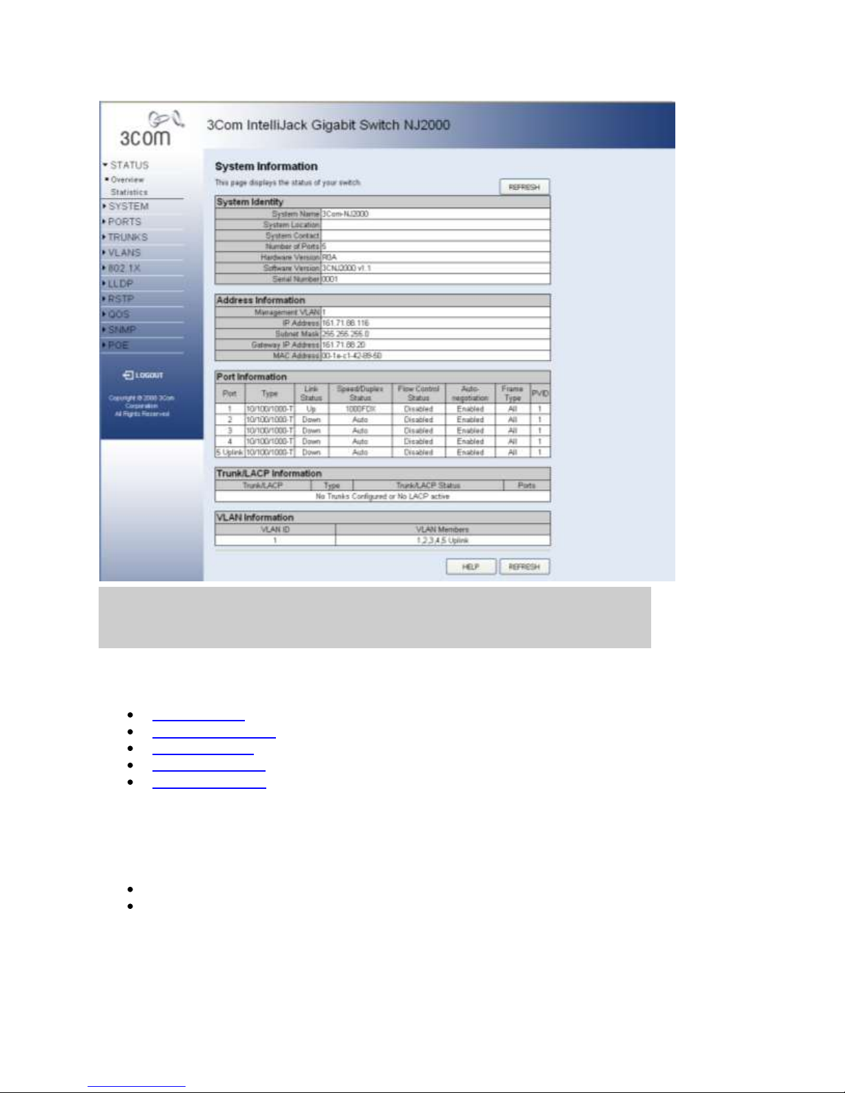
System Information
This page provides an overview of the configuration of the switch. There are five different tables on
this page:
System Identity - Displays general information about the switch.
Address Information - Displays the IP Address configuration of the switch.
Port Information - Displays the configuration of every port on the switch.
Trunk Information - Displays membership information for all trunks.
VLAN Information - Displays the membership information for all VLANs.
Note: This page displays an overview of the switch configuration. To change the switch
configuration, use the Web Management-Interface pages referenced on this page.
There are two main buttons associated with this page:
HELP - Displays this window.
REFRESH - Refreshes the page with the current switch configuration and status
information.
Copyright © 2009 3Com Corporation. All Rights Reserved.
Page 4 of 44
Page 5

3Com Network Jack NJ2000
System Identity
This section contains general information about the switch. System Name, System Location, and
System Contact are set in the SYSTEM > Name page. The Software Version changes when a new
version of software is updated on the switch from the SYSTEM> Tools page. The Number of
Ports, Hardware Version, and Serial Number values are created when the switch is manufactured
and cannot be changed.
Address Information
IP Address, Subnet Mask and Gateway IP Address are set from the SYSTEM > IP Address
page. Management VLAN and MAC Address are fixed during manufacture and are provided here
for information.
Port Information
This table contains one row for each port on the switch. Each row is divided into eight columns as
follows:
Port - The front-panel port number.
Type - All ports on this switch are 10/100/1000BASE-T.
Link Status - Up indicates that the port is connected to another device. Down indicates
there is no connection. The front-panel "image" that is always visible at the top of the page,
also displays this information.
Speed/Duplex Status - An indication of the speed and duplex setting of the port. This is a
number, the speed in Mbps, followed by either FDX for full-duplex or HDX for halfduplex. This can be changed on the PORTS > Configuration page.
Flow Control Status - Enabled indicates that Flow Control has been enabled on the
PORTS > Configuration page.
Auto-negotiation - Auto-negotiation is Enabled by default and is only Disabled when a
Speed/Duplex setting other than Auto is selected on the PORTS > Configuration page.
Frame Type - Tagged means that the port will only send and receive VLAN-tagged
frames. When set to All the port will also send and receive untagged packets. See VLANS
> Port Config for more information.
PVID - The Port VLAN ID. When Frame Type is set to All, untagged packets arriving on
the port will be associated with this VLAN. See VLANS > Port Config for more
information.
Copyright © 2009 3Com Corporation. All Rights Reserved.
Page 5 of 44
Page 6

3Com Network Jack NJ2000
Trunk Information
This table will be empty if no trunks have been configured from the TRUNKS > Membership
page. The table has four columns as follows:
Trunk - The Trunk Label. T1 through T4 may appear in this column.
Type - All trunks and ports on this switch are 10/100/1000M
Trunk Status - An indication of the speed and duplex setting of the trunk. This is a
number, the speed in Mbps, followed by either Full for full-duplex or Half for half-duplex.
This can be changed on the TRUNKS > Settings page.
Ports - The ports that are members of the trunk.
VLAN Information
VLANs can be added on the VLANS > VLAN Setup page. The two columns in this table are used
as follows:
VLAN ID - A number in the range 1 - 4094 which identifies the VLAN.
VLAN Members - A list of the ports that are members of the VLAN. By default, all ports
are members of VLAN 1.
Copyright © 2009 3Com Corporation. All Rights Reserved.
Page 6 of 44
Page 7
3Com Network Jack NJ2000
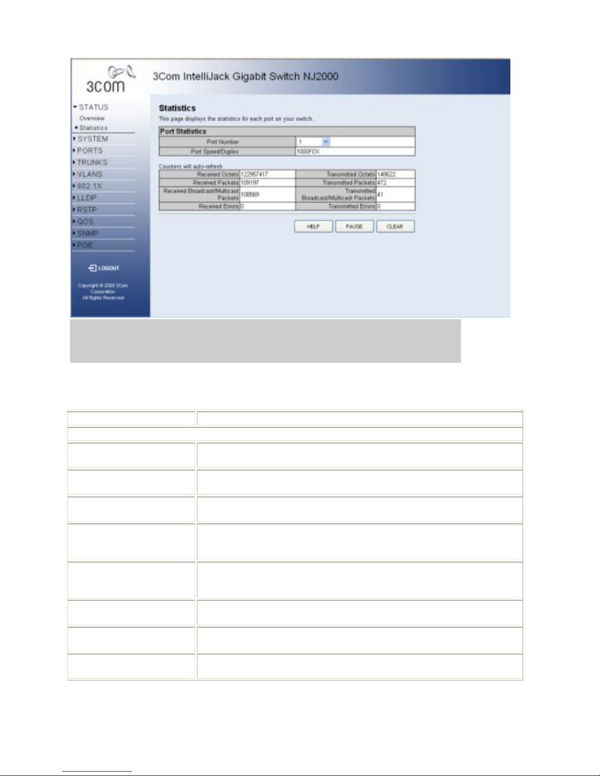
Port Statistics
Parameter
Description
Interface Statistics
Received Octets
The total number of octets received on the interface, including framing
characters.
Received Unicast Packets
The number of subnetwork-unicast packets delivered to a higher-layer
protocol.
Received Errors
The number of inbound packets that contained errors preventing them
from being deliverable to a higher-layer protocol.
Transmitted Multicast
Packets
The total number of packets that higher-level protocols
requested be transmitted, and which were addressed to a multicast
address at this sub-layer, including those that were discarded or not sent.
Transmitted Broadcast
Packets
The total number of packets that higher-level protocols
requested be transmitted, and which were addressed to a broadcast
address at this sub-layer, including those that were discarded or not sent.
Received High Priority
Packets
The total number of received packets that set as High Priority in the QoS
settings.
Transmitted High Priority
Packets
The total number of transmitted packets that set as High Priority in the
QoS settings.
Received Multicast Packets
The number of packets, delivered by this sub-layer to a higher (sub-)layer,
which were addressed to a multicast address at this sub-layer.
You can display statistics on network traffic from the ports. These statistics can be used to identify potential
problems with the switch (such as a faulty port or unusually heavy loading). All values displayed have been
accumulated since the last system reboot, but can be reset to zero by clicking the CLEAR button. The current
statistics are not displayed until you click the REFRESH button.
Copyright © 2009 3Com Corporation. All Rights Reserved.
Page 7 of 44
Page 8

3Com Network Jack NJ2000
Received Broadcast
Packets
The number of packets, delivered by this sub-layer to a higher (sub-)layer,
which were addressed to a broadcast address at this sub-layer.
Transmitted Octets
The total number of octets transmitted out of the interface, including
framing characters.
Transmitted Unicast
Packets
The total number of packets that higher-level protocols
requested be transmitted to a subnetwork-unicast address, including
those that were discarded or not sent.
Transmitted Errors
The number of outbound packets that could not be transmitted because of
errors.
Received Normal Priority
Packets
The total number of received packets that set as High Priority in the QoS
settings.
Transmitted Normal Priority
Packets
The total number of transmitted packets that set as High Priority in the
QoS settings.
There are two main buttons associated with this page:
REFRESH - Resends the information.
CLEAR - Clears all counters and sets them back to zero.
Copyright © 2009 3Com Corporation. All Rights Reserved.
Page 8 of 44
Page 9

3Com Network Jack NJ2000
System Name
This page allows you to change the System Name, System Location, and System Contact. The System Name is
displayed on the Login page, and the SYSTEM > Information page.
System Name - The name of the switch. The System Name can be up to 24 characters long.
System Location - Description of the switch location. The System Location can be up to 24 characters
long.
System Contact - The contact name for the switch. The System Contact can be up to 24 characters long.
Note: The System Name, System Location, and System Contact will accept all characters on the keyboard (i.e.:
numbers, upper-case and lower-case letters, and keyboard symbols).
There are three main buttons associated with this page:
HELP - Displays this window.
APPLY - Updates the switch configuration. No changes are made to the configuration until this
button is pressed.
CANCEL - All changes made to the page are discarded and the switch configuration remains
unchanged.
Copyright © 2009 3Com Corporation. All Rights Reserved.
Page 9 of 44
Page 10
3Com Network Jack NJ2000
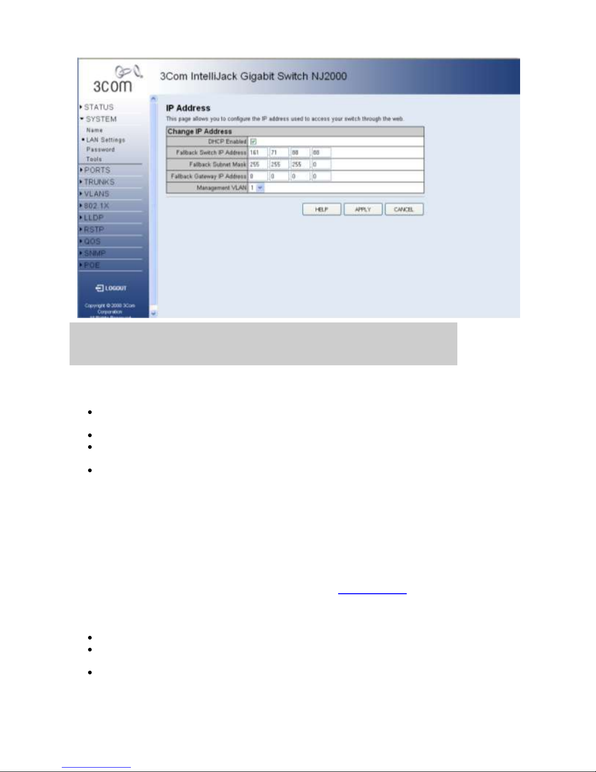
IP Address
I
This page allows you to change the IP Address used by the switch.
DHCP Enabled - If enabled, the IP Address will be assigned from the DHCP server. If disabled, the IP
Address must be assigned manually.
Switch IP Address - The dot-separated IPv4 address used by the switch.
Subnet Mask - The dot-separated IPv4 Subnet address used by the switch. If in doubt, set this to be the
same as the Subnet Mask used by your PC.
Gateway IP Address - The dot-separated IPv4 Gateway address used by the switch. If in doubt, set this to
be the same as the Default Gateway address used by your PC.
Note: If DHCP is enabled, the word "Fallback" will be added to the front of the other parameter names to indicate
the usage of a manually assigned IP Address.
Note: If you change the IP address used by the switch you will lose contact with this Web Management-Interface
and may have to change the IP address on your PC to reconnect.
Note: It is extremely important that you do not forget the IP Address of the switch. If you forget the IP Address you
will have to manually reset the switch to its factory defaults. See the Troubleshooting page for more details. Power
cycle will not reset the IP Address.
There are three main buttons associated with this page:
HELP - Displays this window.
APPLY - Updates the switch configuration. No changes are made to the configuration until this button is
pressed.
CANCEL - All changes made to the page are discarded and the switch configuration remains unchanged
Copyright © 2009 3Com Corporation. All Rights Reserved.
Page 10 of 44
Page 11

3Com Network Jack NJ2000
Password Settings
This page allows you to change the password that is required to access this Web
Management-Interface. You will need to enter the following:
Current Password - The password that you used to login to this interface. There is
no default password.
New Password - Your new password, up to 16 characters long. Passwords are
case-sensitive.
Confirm Password - Re-enter the new password to ensure it has been entered
correctly.
Note: Can be up to 16 characters long and can consist of any alphanumeric characters.
Passwords are case-sensitive.
Note: It is extremely important that you do not forget your password. If you forget your
password, you will have to manually reset the switch to its factory defaults. See the
Troubleshooting page for more details. Power cycle will not reset the password.
There are three main buttons associated with this page:
HELP - Displays this window.
APPLY - Updates the switch configuration. No changes are made to the
configuration until this button is pressed.
CANCEL - All changes made to the page are discarded and the switch
configuration remains unchanged
Copyright © 2009 3Com Corporation. All Rights Reserved.
Page 11 of 44
Page 12
3Com Network Jack NJ2000
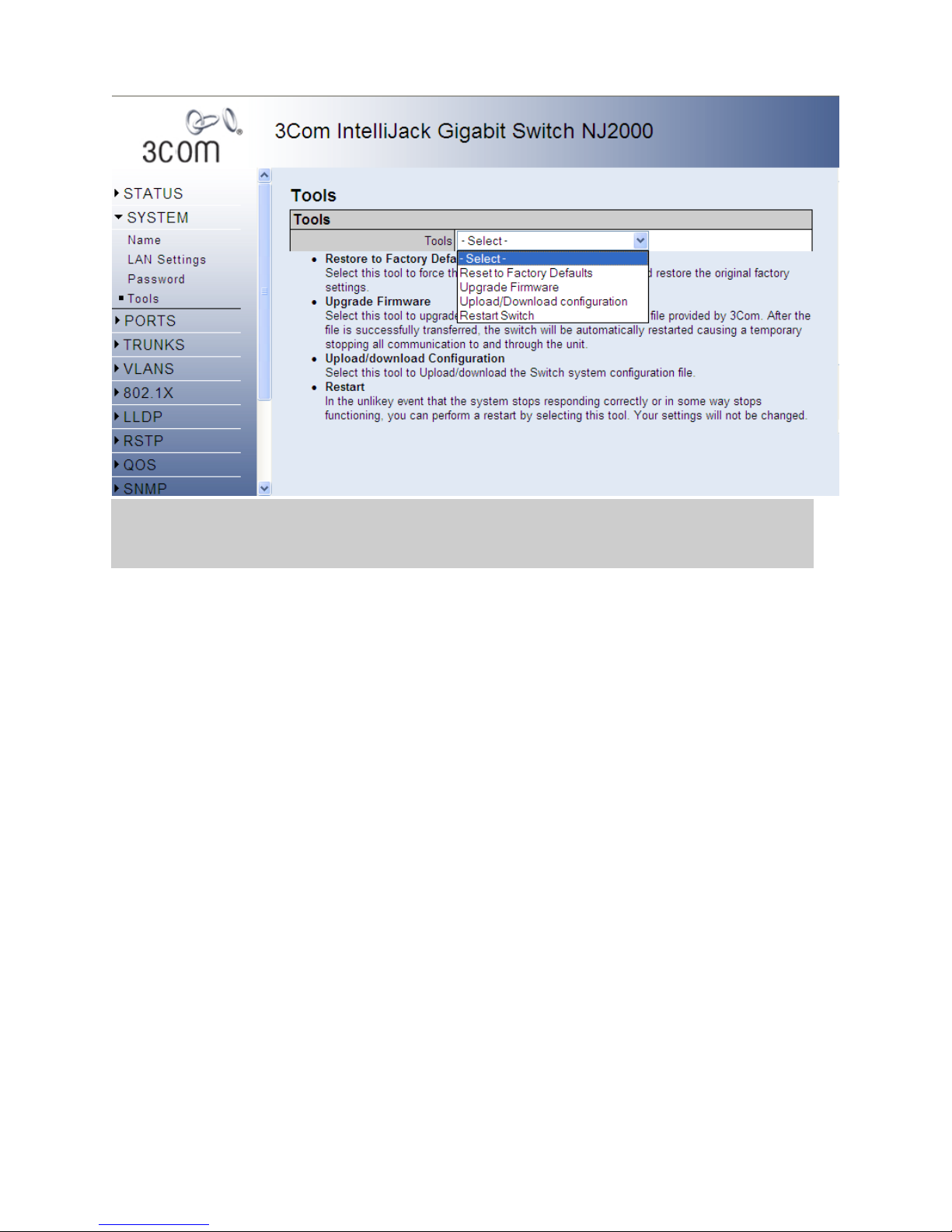
Tools
On the Tools page, you can restore the switch to default settings, upgrade the firmware of
the switch, or restart the switch.
Restore to Factory Defaults
Forces the switch to restore the original factory settings. To reset the switch, select “Reset to
Factory Defaults” from the drop-down list and click APPLY.
Upgrade Firmware
Upgrades the switch system firmware using a file provided by 3Com. Select “Upgrade
Firmware” from the Tools drop-down list then click on the “Browse” button to select the
firmware file. Normally you will use the .wrp file for the upgrade. Click the “APPLY”
button to upgrade the selected switch firmware file. After the file is successfully transferred,
the switch will be automatically restarted/rebooted causing a temporary stopping all
communication to and through the unit. The “System Rebooting” window will appear
during the reboot process. After the reset is complete, the user interface displays the “login“
page.
You can download firmware files for your switch from the Support section of the 3Com
web site at www.3com.com.
Copyright © 2009 3Com Corporation. All Rights Reserved.
Page 12 of 44
Page 13

3Com Network Jack NJ2000
Upload/Download Configuration
To upload or download the configuration file, select “Upload/Download Configuration”
from the Tools drop-down list, then click “Upload” or “Download,” and then click on the
“Browse” button to select the file.
Restart Switch
To restart the switch, select from the Tools drop-down list, and then click APPLY. The reset will be
complete when the user interface displays the login page.
There are three main buttons associated with this page:
HELP - Displays this window.
APPLY - Updates the switch configuration. No changes are made to the configuration until
this button is pressed.
BROWSE - Navigates to a file.
Copyright © 2009 3Com Corporation. All Rights Reserved.
Page 13 of 44
Page 14

3Com Network Jack NJ2000
Port Configuration
This page allows you to configure Jumbo Frames, Speed, Duplex and Flow Control settings for every port
on the switch.
Enable Jumbo Frames - Click box to enable jumbo frames. This setting is applied to all the
ports on the switch.
The Port Configuration table has one row for each port and four columns. The columns are:
Port - The front-panel port-number of the port. This cannot be changed.
Speed/Duplex - A combined data-rate and duplex setting for the port.
Flow Control - Used to control congestion and to minimize the number of dropped packets.
There are three main buttons associated with this page:
HELP - Displays this window.
APPLY - Updates the switch configuration. No changes are made to the configuration until this
button is pressed.
CANCEL - All changes made to the page are discarded and the switch configuration remains
unchanged.
Copyright © 2009 3Com Corporation. All Rights Reserved.
Page 14 of 44
Page 15

3Com Network Jack NJ2000
Speed/Duplex
The Speed and Duplex settings for the port are set by a single drop-down list. The possible values are:
Auto - Speed and duplex settings are auto-negotiated.
10HDX - 10 Mbps, half-duplex
10FDX - 10 Mbps, full-duplex
100HDX - 100 Mbps, half-duplex
100FDX - 100 Mbps, full-duplex
1000FDX - 1000 Mbps, full-duplex
Note: Auto is the default setting and need not be changed unless you are experiencing problems
establishing link with a connected device (i.e. the front-panel LEDs or STATUS > Overview page
indicate that the link is down when there is a cable connecting a device to the switch).
Note: Auto causes the switch to negotiate the link speed and duplex settings with the connected device;
this is called Auto-negotiation. All of the other settings cause Auto-negotiation to be turned off.
Note: In full-duplex mode, both ends of a connection can send traffic at the same time which effectively
doubles the available throughput. In half-duplex mode, only one end of the connection can send traffic at
any one time.
Flow Control
When Flow Control is selected on a port (by clicking on the tick-box in the Flow Control column), the
switch will attempt to slow incoming traffic down when traffic levels are high. It does this by sending
special Pause packets on full-duplex connections or creating back-pressure (deliberately causing
collisions) on half-duplex connections. This can increase traffic throughput by reducing the number of
dropped packets and, as a result, the number of resends that are required. However it is not appropriate in
all circumstances.
Copyright © 2009 3Com Corporation. All Rights Reserved.
Page 15 of 44
Page 16

3Com Network Jack NJ2000
Storm Control
This page allows you to set up a threshold for incoming broadcast and multicast packets. Too many incoming
packets can severely cripple the switch and network performance. Rate limiting protects the switch and network by
keeping the amount of data passing through the ports to a safe limit. The use of VLANs and Trunks to partition ports
and network devices into separate groups can also keep the network from unnecessary traffic by restricting the
packet destination. The same setting is applied to all the ports on the switch.
Enable Storm Control – Click the check box to enable storm control for the specific frame type.
Rate(number of frames per second) – The Rate field is set by a single drop-down list. The same threshold
is applied to every port on the switch. When the threshold is exceeded, packets are dropped, irrespective of
the flow-control settings.
There are three main buttons associated with this page:
HELP - Displays this window.
APPLY - Updates the switch configuration. No changes are made to the configuration until this button is
pressed.
CANCEL - All changes made to the page are discarded and the switch configuration remains unchanged.
Copyright © 2009 3Com Corporation. All Rights Reserved.
Page 16 of 44
Page 17

3Com Network Jack NJ2000
Port Mirroring
This page allows you to copy (mirror) incoming and outgoing packets on multiple ports to a single port. This can be
useful for diagnosing problems. The page is split into two sections:
Port to Mirror to - Choose the destination port. All the mirrored packets will be sent to the selected port.
Ports to Mirror - The front-panel port number.
Note: You cannot mirror the destination port.
There are three main buttons associated with this page:
HELP - Displays this window.
APPLY - Updates the switch configuration. No changes are made to the configuration until this button is
pressed.
CANCEL - All changes made to the page are discarded and the switch configuration remains unchanged.
Copyright © 2009 3Com Corporation. All Rights Reserved.
Page 17 of 44
Page 18

3Com Network Jack NJ2000
Port to Mirror to
Select the destination port from the Port to Mirror to drop-down list. Any port can be selected. The tick-box of the
selected port will be cleared and disabled (see the Ports to Mirror section).
Note: Broadcast and Multicast packets are not mirrored since they are flooded to all ports anyway.
Ports to Mirror
There are two columns in this table. One is titled Port and one is titled Mirroring Enabled.
Port - The front-panel port number.
Mirroring Enabled - This field is associated with the port-number that is displayed immediately on its
left. Click on the tick-box to enable/disable Port Mirroring for the port.
Note: It will not be possible to select Mirroring Enabled for the destination port (the Port to Mirror to).
Copyright © 2009 3Com Corporation. All Rights Reserved.
Page 18 of 44
Page 19

3Com Network Jack NJ2000
Cable Diagnostics
You can perform cable diagnostics for all ports or selected ports to diagnose any cable faults
(short, open etc..) and feedback a distance to the fault.
Cable Diagnostics – Cable diagnostics is performed on a per-port basis. Select the
port number from the drop-down list.
Cable Status – Shows the cable length, operating conditions and isolates a variety of
common faults that can occur on Category 5 twisted pair cabling.
There are two main buttons associated with this page:
HELP - Displays this window.
APPLY - Updates the switch configuration. No changes are made to the configuration until
this button is pressed.
Copyright © 2009 3Com Corporation. All Rights Reserved.
Page 19 of 44
Page 20

3Com Network Jack NJ2000
Trunk Membership
This page allows you to create a maximum of 4 trunks of up to 4 ports each. For instructions on how to create,
modify, and delete trunks, please see Working with Trunks.
The Membership Table has one row for each port and a column for each trunk, plus an additional column for ports
that are not members of a trunk. Each row contains radio buttons which are used to indicate which trunk (if any) the
port belongs to. Each radio button is in a column of its own. The columns are:
Port - The front-panel port number.
Not a Trunk Member - If the radio button in this column is selected, the port is not a member of any
trunks. This is the default state.
Trunk T1 - T4 - These columns correspond to the 4 trunks that are supported by the switch. Clicking on
the radio button in any one of these columns causes the port to become a member of the corresponding
trunk. Each trunk can have a maximum of 4 ports, and a minimum of 2 ports.
When a trunk is first created it is given the following, default configuration:
Speed/Duplex is set to Auto Speed (see TRUNKS > Configuration)
Flow Control is turned off (see TRUNKS > Configuration)
The trunk is a member of VLAN 1 with a PVID of 1. The trunk will accept both tagged and untagged
packets (see VLANS > VLAN Settings)
Ports that are removed from a trunk retain the configuration (i.e. Speed, Duplex, and Flow Control) that they had
when they were members of the trunk. Ports that are added to the trunk after its creation, inherit the current
configuration of the trunk.
You can configure the trunks from the TRUNKS > Configuration page.
Copyright © 2009 3Com Corporation. All Rights Reserved.
Page 20 of 44
Page 21

3Com Network Jack NJ2000
There are three main buttons associated with this page:
HELP - Displays this window.
APPLY - Updates the switch configuration. No changes are made to the configuration until this button is
pressed.
CANCEL - All changes made to the page are discarded and the switch configuration remains unchanged.
Working with Trunks
You can create multiple links between devices that work as one virtual, aggregate link. A port trunk offers a
dramatic increase in bandwidth for network segments where bottlenecks exist, as well as providing a fault-tolerant
link between two devices.
To create a trunk or add a port to an existing trunk (from the TRUNKS > Membership page):
1. Under one of the trunk columns (Trunk T1 to Trunk T4), click the tick-box of the port you would like to
add to the trunk. You can choose a maximum of 4 ports or minimum of 1 port per trunk.
2. Click the APPLY button.
To delete a trunk or remove a port from an existing trunk (from the TRUNKS > Membership page):
1. Under the Not a Trunk Member column, click the tick-box of the port you would like to remove from the
trunk. If you remove all ports from a trunk then the trunk itself will be deleted.
2. Click the APPLY button.
To configure an existing trunk (from the TRUNKS > Configuration page):
1. From the Speed/Duplex drop down menu, you can set the speed and duplex for all the ports in that trunk.
2. Click the Flow Control box to enable or disable flow control for all the ports in that trunk.
Copyright © 2009 3Com Corporation. All Rights Reserved.
Page 21 of 44
Page 22

3Com Network Jack NJ2000
Trunk Setting
This page allows you to change the Speed, Duplex and Flow Control settings for each trunk on the switch. The
Trunk Setting Table has one row for each trunk and four columns. The columns are:
Trunk - The Trunk Label. Trunks are labeled T1 up to T4.
Speed/Duplex - A combined data-rate and duplex setting for the port.
Flow Control - Used to control congestion and to minimize the number of dropped packets.
Member Ports - The individual ports that go together to make the trunk (i.e. the members of the trunk).
Note: When configuring a trunk, all member ports are configured identically.
There are three main buttons associated with this page:
HELP - Displays this window.
APPLY - Updates the switch configuration. No changes are made to the configuration until this button is
pressed.
CANCEL - All changes made to the page are discarded and the switch configuration remains unchanged.
Copyright © 2009 3Com Corporation. All Rights Reserved.
Page 22 of 44
Page 23

3Com Network Jack NJ2000
LACP Setting
This page allows you to configure LACP for each port. The switch supports both static trunking and
dynamic Link Aggregation Control Protocol (LACP). LACP configured ports can automatically negotiate
a trunked link with LACP-configured ports on another device. You can configure any number of ports on
the switch as LACP, as long as they are not already configured as part of a static trunk. If ports on another
device are also configured as LACP, the switch and the other device will negotiate a trunk link between
them. If an LACP trunk consists of more than four ports, all other ports will be placed in a standby mode.
Should one link in the trunk fail, one of the standby ports will automatically be activated to replace it. The
LACP Table has one row for each port and three columns. The columns are:
Port - The front-panel port number.
LACP Enabled on Port - Allows LACP to be enabled or disabled. When the box is checked,
LACP is enabled.
Key Value (0..255, 0 means auto-generated key) - Used to determine the link aggregation
group membership, and to identify this device to other switches during negotiations.
Copyright © 2009 3Com Corporation. All Rights Reserved.
Page 23 of 44
Page 24

3Com Network Jack NJ2000
LACP Status Overview
This page displays the status of the LACP groups.
The LACP Aggregation table has one row for each LACP group. Normal means no LACP group is active. For
active LACP groups, a new row is created from which the status of its port members is displayed. Status of each port
is indicated by a colored box, which use color and number to differentiate status. There are two different tables on
this page:
Aggregation Information - Information on the Link Aggregation Groups.
LACP Port Status - Information includes Protocol Active, Partner Port Number, and Operational Port Key
There are two main buttons associated with this page:
HELP - Displays this window.
REFRESH - Reloads the current page with the latest configuration settings.
Copyright © 2009 3Com Corporation. All Rights Reserved.
Page 24 of 44
Page 25

3Com Network Jack NJ2000
Aggregation Information
The following information is displayed for Link Aggregation Groups:
Aggregation Group - Displays the ID number of the LACP group.
Partner MAC Address - Displays the MAC address of a device in the LACP group that is attached to this
switch.
Local Port Aggregated - Displays port member list of the local LACP group. The port members are ports
on this switch.
Seconds Since Last Changed - Number of seconds since the last LACP was received.
LACP Port Status
The following information is displayed for LACP port status:
Port - Displays the ID number of the LACP group.
Protocol Active - Shows if the port is a member of the active LACP group.
Partner Port Number - The port number on the device in the LACP group that is attached to this port.
Operation Port Key - The current operational value of the key for the LACP group.
Copyright © 2009 3Com Corporation. All Rights Reserved.
Page 25 of 44
Page 26

3Com Network Jack NJ2000
802.1Q VLAN Membership
This page allows you to create up to 64 VLANs. You can also delete the VLANs or make changes to the VLAN
membership and behavior of individual ports. VLANs are powerful but can be difficult to set up properly. If you are
unfamiliar with VLANs please see the Introduction to VLANs. To create a VLAN, enter a VLAN ID into the
VLAN ID field. After clicking the ADD button, you will be directed to the 802.1Q VLAN Group page to add port
members to the VLAN. Each row of the table corresponds to one VLAN.
There are four main buttons associated with this page:
HELP - Display this window.
ADD - Create a VLAN with the inputted VLAN ID.
MODIFY - Choose a VLAN to modify.
DELETE - Delete a VLAN from the VLAN table.
Copyright © 2009 3Com Corporation. All Rights Reserved.
Page 26 of 44
Page 27

3Com Network Jack NJ2000
Introduction to VLANs
VLANs (or Virtual LANs) are logical partitions of the physical LAN. You can use VLANs to:
Increase network performance
Increase internal network security
Create separate broadcast domains
If the network has adequate performance and security for your current needs, it is recommended that you leave the
VLAN settings in the default configuration. The default configuration is as follows:
All ports are members of VLAN 1
The switch management interface is on VLAN 1 (this cannot be changed)
All ports have a Port VLAN ID (PVID) of 1
All ports can send and receive both VLAN-tagged and untagged packets (i.e. they are "hybrid" ports)
In the default configuration, any port is able to send traffic to any other port and a PC connected to any port will be
able to reach the management interface. Broadcast traffic, for example, will be flooded to all ports on the switch.
There are three different parameters that can be configured for each port on the switch; VLAN IDs (VLAN
membership), PVID and Packet Type. Note that the ports within a Trunk cannot be configured individually;
configure the Trunk instead (Trunks are labeled T1 to T4).
VLAN IDs
VLAN 1 is a special VLAN; it cannot be deleted and, if there is a possibility that a port could become
isolated, the Web User-interface will add the port to VLAN 1.
You can add up to 64 VLANs to the configuration of the switch. Each VLAN must be given a VLAN ID in
the range 1-4094.
A port can be a member of up to 64 VLANs.
All packets travelling through the switch are associated with one and only one VLAN.
If a port is not a member of a VLAN, it cannot send or receive packets associated with that VLAN.
A tagged packet carries its VLAN ID in the payload of the packet.
An untagged packet, received on a port with Packet Type set to All, is associated with the VLAN
identified by the PVID.
PVID
The PVID is (Port VLAN ID) is the VLAN ID that is associated with untagged, ingress packets.
It is not possible to remove a port from VLAN 1 unless its PVID has been changed to something other
than 1.
Outgoing packets are tagged unless the packet's VLAN ID is the same as the PVID. When the PVID is set
to "None," all outgoing packets are tagged.
Copyright © 2009 3Com Corporation. All Rights Reserved.
Page 27 of 44
Page 28

3Com Network Jack NJ2000
Packet Type
PCs should be connected to ports with Packet Type set to All. PCs cannot, in general, send or receive
tagged packets.
Switches should be connected to each other with Packet Type set to Tagged.
If the Packet Type is set to All, the port can accept incoming tagged and untagged packets. Untagged
packets will be associated with the VLAN identified by the PVID. Tagged packets will be dropped unless
the port is a member of the VLAN identified by the VLAN tag in the packet. Outgoing packets will be
tagged unless the packet's VLAN ID is the same as the PVID.
If the Packet Type is set to Tagged, the port will drop untagged packets and will only send and receive
tagged packets. Tagged packets will be dropped unless the port is a member of the VLAN identified by the
VLAN tag in the packet. The PVID has no effect in this case.
Copyright © 2009 3Com Corporation. All Rights Reserved.
Page 28 of 44
Page 29

3Com Network Jack NJ2000
802.1Q VLAN Group
After inputting a VLAN ID and clicking the ADD button on the VLAN Setup page, you will be
directed to this page. This page allows you to select the ports to include as a member of the
newly created VLAN.
There are three main buttons associated with this page:
APPLY - Updates the switch configuration. No changes are made to the configuration
until this button is pressed.
CANCEL - All changes made to the page are discarded and the switch configuration
remains unchanged
Copyright © 2009 3Com Corporation. All Rights Reserved.
Page 29 of 44
Page 30

3Com Network Jack NJ2000
802.1Q Per Port Configuration
This page allows you to configure the VLAN parameters for individual ports. VLANs are powerful
but can be difficult to set up properly. If you are unfamiliar with VLANs please see the
Introduction to VLANs. Each row of the table corresponds to one port or trunk; trunked ports
cannot be configured individually. The columns of the table are used as follows:
Port/Trunk - The front-panel port number or the ID of a trunk.
VLAN Aware Enabled - VLAN aware ports are able to use VLAN tagged frames to
determine the destination of the frame. Click to enable or disable VLAN awareness
mode for this port. (Default: Enabled)
Ingress Filtering Enabled - If enabled, incoming frames for VLANs which do not
include this ingress port as a member will be discarded. (Default: Disabled)
PVID - Set the Port VLAN ID. (Default: All)
Packet Type - Set a port's handling of tagged and untagged packets.
(Default: 1)
There are three main buttons associated with this page:
HELP - Displays this window.
APPLY - Saves the settings to memory, and updates the configuration. No changes are
made to the switch's configuration until this button is pressed.
REFRESH - Reloads the current page with the latest configuration setting.
Copyright © 2009 3Com Corporation. All Rights Reserved.
Page 30 of 44
Page 31

3Com Network Jack NJ2000
802.1x Settings
Network switches can provide open and easy access to network resources by simply
attaching a client PC. Although this automatic configuration and access is a desirable
feature, it also allows unauthorized personnel to easily intrude and possibly gain access to
sensitive network data. With IEEE 802.1X (802.1X), access
to all switch ports in a network can be centrally controlled from a server, which means that
authorized users can use the same credentials for authentication from any point within the
network.
There are three main buttons associated with this page:
HELP - Displays this window.
APPLY - Updates the switch configuration. No changes are made to the
configuration until this button is pressed.
REFRESH - Resends the information.
Copyright © 2009 3Com Corporation. All Rights Reserved.
Page 31 of 44
Page 32

3Com Network Jack NJ2000
802.1x Settings
The IEEE 802.1X standard defines a port-based access control procedure that prevents
unauthorized access to a network by requiring users to first submit credentials for
authentication.
System Setting
Mode - Indicates if 802.1X protocol is globally enabled or disabled on the switch.
RADIUS IP - Sets the RADIUS server IP address.
RADIUS UDP Port - Sets the UDP port to the use for the external RADIUS server.
RADIUS Secret - Sets the text string used for encryption between the switch and
the RADIUS server.
Reauthentication Enabled - Sets the client to be re-authenticated after the interval
specified by the Re-authentication Period. Re-authentication can be used to detect
if a new device is plugged into a switch port.
Reauthentication Period - Sets the time period after which a connected client must
be re-authenticated.
EAP timeout - The time the switch shall wait for the supplicant response before re-
transmitting a packet.
Port Setting
Port - The port number.
Admin State - Sets the authentication mode to one of the following options:
o Auto - Requires an 802.1X-aware client to be authorized by the
authentication server. Clients that are not 802.1X-aware will be denied
access.
o Force-Authorized - Forces the port to grant access to all clients, either
802.1X-aware or otherwise.
o Force-Unauthorized - Forces the port to deny access to all clients, either
802.1X-aware or otherwise.
Port State - The state of the port.
Reset - Two options available:
o Re-Authenticate - Schedules a reauthentication to whenever the quiet-
period of the port runs out.
o Force-Reinitialize - Bypasses the quiet-period of the port and enables
immediate reauthentication regardless of the status for the quiet-period.
Copyright © 2009 3Com Corporation. All Rights Reserved.
Page 32 of 44
Page 33

3Com Network Jack NJ2000
802.1x Statistics
Displays 802.1x statistics
There are two main buttons associated with this page:
HELP - Displays this window.
REFRESH - Resends the information.
Port Statistics - Statistics can be viewed on a per-port basis. Select the port that you want
to view here.
Authenticator counters - General statistics for authenticator.
Backend Authenticator counters - General statistics for RADIUS server.
802.1X MIB counters - MIB module defined for 802.1X.
Other statistics
Copyright © 2009 3Com Corporation. All Rights Reserved.
Page 33 of 44
Page 34

3Com Network Jack NJ2000
LLDP Configuration
This page allows you to setup the LLDP configuration.
The LLDP State table contains a row for each port and two columns. The two columns are:
Port - The front-panel port number.
State - You can choose to disable or enable LLDP for each port. Enabling LLDP will allow the port to
receive and transmit TLVs.
There are three main buttons associated with this page:
HELP - Displays this window.
APPLY - Updates the switch configuration. No changes are made to the configuration until this button is
pressed.
REFRESH - Reloads the current page with the latest configuration settings.
LLDP
Link Layer Discovery Protocol (LLDP) allows devices on the network to share information about themselves for the
reasons of simplified troubleshooting, enhanced network management, and maintaining an accurate network
topology. LLDP-capable devices periodically transmit information in messages called Type Length Value (TLV)
fields to neighbor devices. This information includes port description, system name, system description, system
capabilities, and management address.
Copyright © 2009 3Com Corporation. All Rights Reserved.
Page 34 of 44
Page 35

3Com Network Jack NJ2000
LLDP Neighbor Table
This page displays the LLDP Neighbor Table, which provides information on neighboring
devices. The table contains the following seven columns:
Local Port - The local port of the switch.
Chassis ID - The chassis information where the device is located.
Remote Port ID - The remote port ID on the neighboring device.
System Name - The devices full name.
Port Description - The port description and information of the neighboring device.
System Capabilities - The system capabilities information of the device.
Management Address - Displays the management address.
There are two main buttons associated with this page:
HELP - Displays this window.
REFRESH - Reloads the current page with the latest configuration settings.
Copyright © 2009 3Com Corporation. All Rights Reserved.
Page 35 of 44
Page 36

3Com Network Jack NJ2000
RSTP Setting
This page enables you to setup the configuration of RSTP. RSTP is a protocol that prevents loops in
the network and dynamically reconfigures which physical links in a switch should forward frames.
The page is composed of two tables:
RSTP System Configuration - Configure global system settings.
RSTP Port Configuration - Setup port related settings.
There are three main buttons associated with this page:
HELP - Displays this window.
APPLY - Updates the Switch configuration. No changes are made to the configuration until
this button is pressed.
REFRESH - Refreshes the page with the current RSTP configuration.
Copyright © 2009 3Com Corporation. All Rights Reserved.
Page 36 of 44
Page 37

3Com Network Jack NJ2000
STA Introduction
The Spanning Tree Algorithm (STA) can be used to detect and disable network loops, and
to provide backup links between switches, bridges or routers. This allows the switch to
interact with other bridging devices (that is, an STA-compliant switch, bridge or router) in
your network to ensure that only one route exists between any two stations on the network,
and provide backup links which automatically take over when a primary link goes down.
The spanning tree algorithms supported by this switch include these versions:
STP Spanning Tree Protocol (IEEE 802.1D)
RSTP Rapid Spanning Tree Protocol (IEEE 802.1w)
RSTP System Configuration
There are five configurable parameters in this table. As follows:
System Priority - This parameter configures the spanning tree priority globally for
this switch. The device with the highest priority becomes the STA root device.
However, if all devices have the same priority, the device with the lowest MAC
address will then become the root device. Number between 0 - 61440 in increments
of 4096. Therefore, there are 16 distinct values.
Hello Time - Interval (in seconds) at which the root device transmits a
configuration message (BPDU frame). Number between 1 - 10 (default is 2).
Max Age - The maximum time (in seconds) a device can wait without receiving a
configuration message before attempting to reconfigure. That also means the
maximum life time for a BPDU frame. Number between 6 - 40 (default is 20).
Forward Delay - The maximum time (in seconds) the root device will wait before
changing states (i.e., discarding to learning to forwarding). Number between 4 - 30
(default is 15).
Force Version - Set and show the RSTP protocol to use. Normal - use RSTP,
Compatible - compatible with STP.
RSTP Port Configuration
The table has one row for each port and four columns. The columns are:
Port - The port ID. It cannot be changed. Aggregations mean any configured trunk
group.
Enabled - Click on the tick-box to enable/disable the RSTP protocol for the port.
Edge - Expect the port to be an edge port (linking to an end station) or a link to
another STP device.
Path Cost - This parameter is used by the STP to determine the best path between
devices. Therefore, lower values should be assigned to ports attached to faster
media, and higher values assigned to ports with slower media. Set the RSTP path
cost on the port. Number between 0 - 200000000. 0 means auto-generated path
cost.
Copyright © 2009 3Com Corporation. All Rights Reserved.
Page 37 of 44
Page 38

3Com Network Jack NJ2000
RSTP status
This page shows RSTP bridge and port states. There are two tables on this page:
RSTP Bridge Overview - Show the RSTP settings for the whole switch.
RSTP Port Status - Detailed RSTP information for each port.
There are two main buttons associated with this page:
HELP - Displays this window.
REFRESH - Refreshes the page with the current status.
RSTP Bridge Overview
The RSTP Bridge Overview table has one row to display settings for the whole switch.
Hello Time, Maximum Age and Forward Delay are displayed. Topology shows the switch
current state. Root ID indicates the root port ID for the switch.
RSTP Port Status
The table has one row for each port and seven columns. The columns are:
Port/Trunk - Port/Trunk ID number.
Path Cost - Show the path cost on this port.
Edge Port - Yes if the port is an edge port which connects to an end station.
P2p Port - Yes if the port link is connected to another STP device.
Protocol - Show the running protocol, RSTP or STP.
Port Role - Show the current port role
Copyright © 2009 3Com Corporation. All Rights Reserved.
Page 38 of 44
Page 39

3Com Network Jack NJ2000
QOS Configuration
QoS (Quality of Service) is a mechanism which is used to prioritize certain traffic as it is moves through the switch.
Traffic can be classified as High, Medium, Normal or Low priority. This switch features both strict priority-based
and weighted round-robin (WRR) forwarding, with guaranteed bandwidth allocation for the different QOS classes.
The queuing method can be selected using the Queue Mode drop-down list:
Strict priority - Higher priority frames take precedence over lower priority frames during forwarding. In
case of congestion, the lowest priority traffic is dropped before higher priority frames. Head-of-queue
blocking maybe encountered by using this mode.
WRR - In this mode, all priorities can be guaranteed a share of the bandwidth when the system is
overloaded. The bandwidth sharing percentage can be adjusted by specifying the four QOS class with
different ratio in WRR Weight, which appears after WRR is enabled in Queue Mode.
Note: WRR is selectable when Jumbo Frame is disabled in Ports > Settings.
You can select how traffic is prioritized by using one of the three QoS modes which is selected using the QoS Mode
drop-down list:
QoS Disabled - QoS is turned off and all packets have equal priority.
802.1p - Packets are prioritized using the content of the VLAN-tag.
DSCP - Packets are prioritized using the DSCP (Differentiated Services Code Point) value.
Note: Only one QoS mode can be active at one time. It is not possible, for example, to prioritize traffic using the
DSCP and 802.1p
Copyright © 2009 3Com Corporation. All Rights Reserved.
Page 39 of 44
Page 40

3Com Network Jack NJ2000
There are three main buttons associated with this page:
HELP - Displays this window.
APPLY - Saves the settings to memory, and updates the configuration. No changes
are made to the switch's configuration until this button is pressed.
REFRESH - Reloads the current page with the latest configuration setting.
802.1p
The 802.1p field is held within the VLAN-tag of a packet. The field is three bits long so can
hold eight values; 0 - 7 inclusive. When QoS Mode is set to 802.1p, the 802.1p
Configuration table appears which allows a priority to be set for each of the eight values.
You can use the Prioritize Traffic drop-down list to quickly set the values in the 802.1p
Configuration table. Select All Low Priority to set all values to low priority, All Normal
Priority to set all values to normal priority, All Medium Priority to set all values to
medium priority, or select All High Priority to set all values to high priority. Use Custom
if you want to set each value individually.
Note: Because end-stations, like PCs, are not usually VLAN aware, they do not create
VLAN-tagged frames. As a result, this method of prioritization is not ideal when there are a
lot of PCs connected to the Switch.
DSCP
The Differentiated Services Code Point (DSCP) is a six bit field that is contained within an
IP (TCP or UDP) header. Six bits allows the DSCP field to take any value in the range 0 63 inclusive. When QoS Mode is set to DSCP, the DSCP Configuration table appears
which allows a priority to be set for each of the DSCP values.
You can use the Prioritize Traffic drop-down list to quickly set the values in the DSCP
Configuration table. Select All Low Priority to set all values to low priority, All Normal
Priority to set all values to normal priority, All Medium Priority to set all values to
medium priority, or select All High Priority to set all values to high priority. Use Custom
if you want to set each value individually.
Copyright © 2009 3Com Corporation. All Rights Reserved.
Page 40 of 44
Page 41

3Com Network Jack NJ2000
SNMP Configuration
This page allows you to configure the Simple Network Management Protocol (SNMP). The SNMP agent
permits the switch to be managed from any system in the network using management software. You can
set the following options:
SNMP Enabled -Activate or deactivate SNMP.
SNMP Trap Destination - IP address of the trap manager.
Traps indicating status changes are issued by the switch to specified trap managers. You must
specify trap managers so that key events are reported by this switch to your management station.
SNMP trap destination specifies the IP address of the trap manager.
SNMP Read Community - A community string that acts like a password and permits access to
the SNMP protocol. The read community string specifies read-only access. Authorized
management stations are only able to retrieve MIB objects.
SNMP Write Community - Specifies read-write access. Authorized management stations are
able to both retrieve and modify MIB objects.
SNMP Trap Community - Community string sent with the notification operation.
There are three main buttons associated with this page:
HELP - Displays this window.
APPLY - Updates the switch configuration. No changes are made to the configuration until this
button is pressed.
CANCEL - All changes made to the page are discarded and the switch configuration remains
unchanged.
Copyright © 2009 3Com Corporation. All Rights Reserved.
Page 41 of 44
Page 42

3Com Network Jack NJ2000
PoE (Power over Ethernet) Settings
The switch can provide DC power to a wide range of connected devices, eliminating the
need for an additional power source and cutting down on the amount of cables attached to
each device. Once configured to supply power, an automatic detection process is initialized
by the switch that is authenticated by a PoE signature from the connected device. Detection
and authentication prevent damage to non-802.3af compliant devices.
The switch’s power management enables total switch power and individual port power to be
controlled within the switch power budget. PSE ethernet ports 1 and 2 are capable of
delivering 802.3af PoE. Port power can be automatically turned on and off for connected
devices, and a per-class power priority can be set so that the switch never exceeds its power
budget. When a device is connected to a switch port, its power requirements are detected
and classified by the switch before power is supplied. If the power required by a device
exceeds the power budget of the port or the whole switch, power is not supplied.
The power source for the NJ2000 determines if PSE ethernet ports 1 and 2 can be used as
802.3af ports. If the NJ2000 uplink port (PD) is connected to a high-power midspan 802.3at
POE device or the external 48VDC power adapter is being used, PSE ethernet ports 1 and 2
can be used as 802.3af ports, 15.4W power budget. If power is provided to the NJ2000 thru
the uplink port connected to a regular 802.3af PoE, then Ethernet ports 1 and 2 cannot be
used as 802.3af ports.
PSE ethernet ports 1 and 2 can be configured to one of two power priority levels, high and
low. To control the power supply within the switch’s budget, ports set at high priority have
power enabled in preference to those ports set at low priority with the same PD class. For
example, when a device is connected to a port set to high priority, the switch supplies the
required power, if necessary by dropping power to ports set for a lower priority. If power is
dropped to some low-priority ports and later the power demands on the switch fall back
within its budget, the dropped power is automatically restored.
Copyright © 2009 3Com Corporation. All Rights Reserved.
Page 42 of 44
Page 43

3Com Network Jack NJ2000
Each device (PD) that is connected to the PSE ethernet ports will have a PD class. This will
limit the number of devices powered thru the PSE Ethernet ports 1 and 2.
The NJ2000 can power:
One class 0 or 3 PD or
Two class 2 PD’s
Two class 1 PD’s or
One class 1 PD and One class 2 PD.
Switch Power Status
Displays the Power over Ethernet parameters for the switch.
Power Consumed – Displays the percentage of power budget (15.4W) being
drawn by attached devices.
Port – The port number.
PoE Enabled – The administrative status of PoE power on the port.
Delivering Power – The current operating status of PoE power on the port.
Current – The current power consumption on the port.
Priority – The port’s configured power priority setting. (Range: Low, High;
Default: Port 1 as High, Port 2 as Low)
PD Class – The current power device class on the port.
There are three main buttons associated with this page:
HELP - Displays this window.
APPLY - Updates the switch configuration. No changes are made to the
configuration until this button is pressed.
REFRESH - Resends the information.
Copyright © 2009 3Com Corporation. All Rights Reserved.
Page 43 of 44
Page 44

3Com Network Jack NJ2000
Troubleshooting
Forgot or Lost Password
If you have forgotten the administration password you can return the switch to its factory default
state by following these steps:
Press reset button (Feature 7) for at least for 20 seconds.
After completing this procedure, the password will be “password”.
Feature
Description
1
4 Gigabit LAN switch
ports with LEDs
Allows you to connect up to four devices to the network.
2
Two pass-through ports
The pass-through ports bypass the functionality of the switch and are directly wired to the
associated pass-through ports on the rear of the unit.
3
Power LEDs
Indicate whether the NJ2000 is being powered by a local power supply (DC) or PoE.
4
Uplink LED
Indicates network connection status for the uplink port on the rear of the unit.
5
Local Power Socket
Can be used to power the NJ2000 with the optional local power supply, 3CNJ1000PSL.
6
Locking screw hole
Used to secure the NJ2000 to the wall-mount plate.
7
Reset Button
•Press and hold <20 seconds to reset the NJ2000
•Press and hold >20 seconds to erase the password and reset the unit to factory defaults
Copyright © 2009 3Com Corporation. All Rights Reserved.
Page 44 of 44
 Loading...