

Page 1

HP Dual-port 4x Fabric Adapter
User Guide
November 2004 (Second Edition)
Part Number 377704-002
Page 2

© Copyright 2004 Hewlett-Packard Development Company, L.P.
The information contained herein is subject to change without notice. The only warranties for HP products and
services are set forth in the express warranty statements accompanying such products and services. Nothing herein
should be construed as constituting an additional warranty. HP shall not be liable for technical or editorial errors
or omissions contained herein.
HP Dual-port 4x Fabric Adapter User Guide
November 2004 (Second Edition)
Part Number 377704-002
Page 3

Table of Contents
Regulatory Model Number ..........................................................................................................................v
Federal Communications Commission Notice ............................................................................................v
Declaration of Conformity for Products marked with the FCC Logo, United States Only....................... vi
Modifications ............................................................................................................................................. vi
Cables......................................................................................................................................................... vi
Canadian Notice (Avis Canadien) ............................................................................................................. vi
European Union Regulatory Notice........................................................................................................... vi
Japanese Notice......................................................................................................................................... vii
Korean Notice ........................................................................................................................................... vii
BSMI Notice ............................................................................................................................................. vii
Electrostatic Discharge ............................................................................................................................ viii
Preventing Electrostatic Damage................................................................................................ viii
Grounding Methods To Prevent Electrostatic Damage .............................................................. viii
Contact Information................................................................................................................................. viii
i
1: About the Host Channel Adapter (HCA) .................... 1
HP Dual-port 4x Fabric Adapters ................................................................................................................1
Supported Protocols........................................................................................................................ 1
HCA Package Contents .................................................................................................................. 2
About the HCA Drivers ...............................................................................................................................2
IPoIB............................................................................................................................................... 2
Socket Direct Protocol (SDP) ......................................................................................................... 2
uDAPL ............................................................................................................................................ 2
SCSI RDMA (SRP) ........................................................................................................................ 2
MPI ................................................................................................................................................. 2
Linux Kernels ................................................................................................................................. 3
About Boot Over InfiniBand Functionality .................................................................................................3
How Boot Over IB Works .............................................................................................................. 3
Value of Boot over IB..................................................................................................................... 3
2: Installing the Host Channel Adapter (HCA) ............... 5
Requirements ...............................................................................................................................................5
Installation Overview...................................................................................................................................5
Selecting the Host Connector ......................................................................................................................6
Selecting PCI-X Connector(s) ........................................................................................................ 6
Selecting PCI-Express Connector(s) .............................................................................................. 7
Warnings......................................................................................................................................... 7
Selecting the Type of Installation ................................................................................................................8
Installing a High Profile HCA in a PCI-X Connector .................................................................... 8
Installing a Low Profile HCA in a PCI-X Connector..................................................................... 9
Page 4

ii
Installing Two HCAs in One Host with PCI-X Connectors......................................................... 10
Installing HCA(s) in a 1U Host with PCI-Express Connectors.................................................... 11
Installing HCA(s) in a 2U+ Host with PCI-Express Connectors.................................................. 12
Connecting the InfiniBand Cables.............................................................................................................12
3: Installing the HCA Drivers........................................ 15
About the Installation.................................................................................................................................15
Installing HCA Host Drivers .....................................................................................................................15
Verify the HCA and Driver Installation.....................................................................................................18
Check the HCA............................................................................................................................. 18
Verify the HCA and Server Communication................................................................................ 19
Check the Modules ....................................................................................................................... 19
Verify the HCA Initialization ....................................................................................................... 20
Upgrading the Firmware on the HCA........................................................................................................20
Determine the Card Type.............................................................................................................. 21
Upgrade the Firmware .................................................................................................................. 21
4: Configuring IPoIB Drivers ........................................ 23
Assign Interfaces to HCAs.........................................................................................................................23
About Assigning Interface for Single HCAs ................................................................................ 23
About Assigning Interfaces for Multiple HCAs ........................................................................... 23
View all the Interfaces .................................................................................................................. 24
Create Interface Partitions..........................................................................................................................25
About Dividing an Interface ......................................................................................................... 25
Configuring a Subinterface........................................................................................................... 26
Verify IPoIB Connectivity............................................................................................................ 26
Deleting an Interface Partition...................................................................................................... 27
Run an IPoIB Performance Test ................................................................................................................27
5: Configuring MPI Drivers........................................... 29
Configure MPI ...........................................................................................................................................29
Configure SSH.............................................................................................................................. 30
Edit PATH Variable...................................................................................................................... 31
Perform Bandwidth Test............................................................................................................... 32
Perform Latency Test.................................................................................................................... 32
6: Configuring SDP Drivers.......................................... 35
Configure IPoIB Interfaces........................................................................................................................35
Specify Connection Overrides ...................................................................................................................35
Convert Sockets-Based Applications.........................................................................................................35
Converting Sockets-Based Applications to Use SDP................................................................... 36
Run a Performance Test on SDP ...............................................................................................................37
Sample Configuration - OracleNet™ Over SDP for Oracle 9i..................................................................38
Performance Acceleration............................................................................................................. 38
Page 5

Overview....................................................................................................................................... 38
Sample Topology.......................................................................................................................... 38
Configure the Application Server ................................................................................................. 39
Configure the Database Server ..................................................................................................... 39
Set Up Non-IB Connections ......................................................................................................... 40
Troubleshoot the Configuration.................................................................................................... 40
7: Configuring SRP Drivers.......................................... 41
Auto-Mount SRP Devices .........................................................................................................................41
Verify Configurations from the Host.........................................................................................................41
Verify the SCSI Devices from the Host........................................................................................ 41
Special Considerations...............................................................................................................................44
Scenario ........................................................................................................................................ 44
SRP Sample Configuration........................................................................................................................45
Sample SRP/Storage Topology .................................................................................................... 45
Viewing the Storage Configuration .............................................................................................. 45
Viewing the SRP Host .................................................................................................................. 46
View the Topology ....................................................................................................................... 47
Configure the Fibre Channel Gateway ......................................................................................... 48
Verify Configurations from the Host............................................................................................ 51
Verify SRP Functionality.............................................................................................................. 52
Configure the SRP Target............................................................................................................. 54
iii
8: Configuring uDAPL Drivers...................................... 59
About the uDAPL Configuration...............................................................................................................59
Building uDAPL Applications...................................................................................................................59
Run a uDAPL Performance Test ...............................................................................................................60
Run a uDAPL Throughput Test.................................................................................................... 60
Run a uDAPL Latency Test.......................................................................................................... 61
9: Troubleshooting the HCA Installation ...................... 63
Interpret HCA LEDs..................................................................................................................................63
Check the InfiniBand Cable.......................................................................................................................64
Check the InfiniBand Network Interfaces .................................................................................................64
Run the HCA Self-Test..............................................................................................................................65
10: Sample Test Plan................................................... 67
Overview....................................................................................................................................................67
Requirements .............................................................................................................................................67
Prerequisites.................................................................................................................................. 67
Hardware and Applications .......................................................................................................... 67
Network Topology.....................................................................................................................................68
Host and Switch Setup...............................................................................................................................68
IPoIB Setup................................................................................................................................................69
Page 6

iv
About IPoIB.................................................................................................................................. 69
Configuring IPoIB ........................................................................................................................ 69
IPoIB Performance vs Ethernet Using netperf...........................................................................................70
Perform a Throughput Test........................................................................................................... 70
Perform a Latency Test................................................................................................................. 71
SDP Performance vs IPoIB Using netperf.................................................................................................71
About SDP .................................................................................................................................... 71
Configuring SDP........................................................................................................................... 71
Perform a Throughput Test........................................................................................................... 72
Perform a Latency Test................................................................................................................. 72
Page 7

Regulatory Notices
Regulatory Model Number
For the purpose of regulatory compliance certifications and identification, this product has been
assigned a unique regulatory model number. The regulatory model number can be found on the product
nameplate label, along with all required approval markings and information. When requesting
compliance information for this product, always refer to this regulatory model number. The regulatory
model number is not the marketing name or model number of the product.
v
Federal Communications Commission Notice
This equipment has been tested and found to comply with the limits for a Class B digital device,
pursuant to Part 15 of the FCC Rules. These limits are designed to provide reasonable protection against
harmful interference in a residential installation. This equipment generates, uses, and can radiate radio
frequency energy and, if not installed and used in accordance with the instructions, may cause harmful
interference to radio communications. However, there is no guarantee that interference will not occur in
a particular installation. If this equipment does cause harmful interference to radio or television
reception, which can be determined by turning the equipment off and on, the user is encouraged to try to
correct the interference by one or more of the following measures:
• Reorient or relocate the receiving antenna.
• Increase the separation between the equipment and receiver.
• Connect the equipment into an outlet on a circuit that is different from that to which the receiver is
connected.
• Consult the dealer or an experienced radio or television technician for help.
Page 8

vi
Declaration of Conformity for Products marked with
the FCC Logo, United States Only
This device complies with Part 15 of the FCC Rules. Operation is subject to the following two
conditions: (1) this device may not cause harmful interference, and (2) this device must accept any
interference received, including interference that may cause undesired operation.
For questions regarding your product, contact us by mail or telephone:
Hewlett-Packard Company
P. O. Box 692000, Mail Stop 530113
Houston, Texas 77269-2000
1-800-652-6672 (For continuous quality improvement, calls may be recorded or monitored.)
For questions regarding this FCC declaration, contact us by mail or telephone:
Hewlett-Packard Company
P. O. Box 692000, Mail Stop 510101
Houston, Texas 77269-2000
1-281-514-3333
To identify this product, refer to the part, series, or model number found on the product.
Modifications
The FCC requires the user to be notified that any changes or modifications made to this device that are
not expressly approved by Hewlett-Packard Company may void the user’s authority to operate the
equipment.
Cables
Connections to this device must be made with shielded cables with metallic RFI/EMI connector hoods
in order to maintain compliance with FCC Rules and Regulations.
Canadian Notice (Avis Canadien)
This Class B digital apparatus meets all requirements of the Canadian Interference-Causing Equipment
Regulations
Cet appareil numérique de la classe B respecte toutes les exigences du Règlement sur le matériel
brouilleur du Canada
.
European Union Regulatory Notice
This product complies with the following EU Directives:
•Low Voltage Directive 73/23/EEC
Page 9

•EMC Directive 89/336/EEC
Compliance with these directives implies conformity to applicable harmonized European standards (European Norms) which are listed on the EU Declaration of Conformity issued by Hewlett-Packard for this product or product family.
This compliance is indicated by the following conformity marking placed on the
product:
vii
This marking is valid for non-Telecom products
and EU harmonized Telecom products (e.g. Bluetooth).
Japanese Notice
Korean Notice
This marking is valid for EU non-harmonized Telecom products .
*Notified body number (used only if applicable - refer to the product label)
xxxx*
BSMI Notice
Page 10

viii
Electrostatic Discharge
Preventing Electrostatic Damage
A discharge of static electricity from a finger or other conductor may damage system boards or other
static-sensitive devices. This type of damage may reduce the life expectancy of the device.
To prevent electrostatic damage when setting up the system or handling parts:
• Avoid hand contact by transporting and storing products in static-safe containers.
• Keep electrostatic-sensitive parts in their containers until they arrive at static-free workstations.
• Place parts on a grounded surface before removing them from their containers.
• Avoid touching pins, leads, or circuitry.
• Handle parts by edges only.
• Avoid contact between the parts and clothing (for example, a wool sweater) . Wrist straps only
protect parts of the body from ESD voltages.
• Do not wear jewelry.
• Always be properly grounded when touching a static-sensitive component or assembly.
Grounding Methods To Prevent Electrostatic
Damage
There are several methods for grounding. Use one or more of the following methods when handling or
installing electrostatic-sensitive parts:
• Use a wrist strap connected by a ground cord to a grounded workstation or computer chassis. Wrist
straps are flexible straps with a minimum of 1 megohm ± 10 percent resistance in the ground cords.
To provide proper ground, wear the strap snug against the skin.
• Use heel straps, toe straps, or boot straps at standing workstations. Wear the straps on both feet
when standing on conductive floors or dissipating floor mats.
• Use conductive field service tools.
• Use a portable field service kit with a folding static-dissipating work mat.
If you do not have any of the suggested equipment for proper grounding, have an authorized reseller
install the part.
For more information on static electricity, or assistance with product installation, contact your
authorized reseller.
Contact Information
Table 2-1: Customer Contact Information
For the name of your nearest authorized
HP reseller:
In the United States, call 1-800-345-1518.
In Canada, call 1-800-263-5868.
Page 11

Table 2-1: Customer Contact Information
For HP technical support: In the United States and Canada, call 1-800-HP-INVENT
(1-800-474-6836). This service is available 24 hours a day,
7 days a week. For continuous quality improvement, calls
may be recorded or monitored.
Outside the United States and Canada, refer to
www.hp.com
ix
Page 12

x
Page 13

About the Host Channel Adapter (HCA)
This document provides the following information:
• “HP Dual-port 4x Fabric Adapters” on page 1
• “About the HCA Drivers” on page 2
• “About Boot Over InfiniBand Functionality” on page 3
1
1
HP Dual-port 4x Fabric Adapters
This document describes the following HCAs:
• HP NC570C PCI-X Dual-port 4x Fabric Adapter
• HP NC571C PCI Express Dual-port 4x Fabric Adapter
Both HCAs provide 4x InfiniBand
each direction. Each HCA and associated protocol drivers are designed to run in conjunction with an HP
Dual-port 4x Fabric Adapter. The HP Dual-port 4x Fabric Adapters feature a full suite of upper-layer
protocols and APIs.
Supported Protocols
• IPoIB - Internet Protocol over InfiniBand. Refer to “IPoIB” on page 2 or “Configuring IPoIB
Drivers” on page 23.
• SDP - Socket Direct Protocol. Refer to “Socket Direct Protocol (SDP)” on page 2 or “Configuring
SDP Drivers” on page 35.
• uDAPL - User Direct Access Programming Library. Refer to “uDAPL” on page 2 or “Configuring
uDAPL Drivers” on page 59
• SRP - SCSI RDMA Protocol. Refer to “SCSI RDMA (SRP)” on page 2 or “Configuring SRP
Drivers” on page 41.
• MPI - Message Passing Interface. Refer to page 2 or “Configuring MPI Drivers” on page 29
™ copper connectors which provide 10Gbps connections per port in
Page 14

2
HCA Package Contents
Inspect all items for shipping damage. If anything appears to be damaged, or if you encounter problems
when installing or configuring your system, contact a customer service representative.
The HP Dual-port 4x Fabric Adapters ship with the following components:
• One HP Dual-port 4x Fabric Adapter
• HP Dual-port 4x Fabric Adapter Quick Setup Instructions
• Limited Warranty and Material Limitations Documentation
About the HCA Drivers
The HP Dual-port 4x Fabric Adapters provide a full suite of upper-layer protocols, including IPoIB,
SD P, SRP, M PI a n d uD A P L.
IPoIB
IPoIB is a required protocol; it allows the IP network to utilize the InfiniBand fabric. It is used by SDP
and uDAPL to resolve IP addresses. IPoIB is configured like a normal Ethernet interface. During the
installation process, ib interface names are automatically added to the network configuration. These
correspond to the ports on the HCA.
Socket Direct Protocol (SDP)
The Socket Direct Protocol (SDP) is a high-performance, zero-copy data-transfer protocol used for
stream-socket networking over an InfiniBand fabric. The driver can be configured to automatically
translate TCP to SDP based on source IP, destination, or program name.
uDAPL
The User Direct Access Programming Library (uDAPL) defines a set of APIs that exploits RDMA
capabilities. uDAPL is installed transparently with the driver library. Your application must explicitly
support uDAPL. uDAPL is transparently installed and requires no further configuration. However, if
your application supports uDAPL, it may require additional configuration changes. Please refer to your
application documentation for more information.
SCSI RDMA (SRP)
The SCSCI RDMA (SRP) protocol runs SCSI commands across RDMA-capable networks for
InfiniBand hosts to communicate with Fibre Channel storage devices. This information is used to assign
devices and mount file-systems so that the data on those file-systems is accessible to the host.
The SRP driver is installed as part of the driver package, and is loaded automatically upon host reboot.
Use of this protocol requires that a Fibre Channel gateway be present in the chassis.
MPI
The MPI protocol is bundled with the Upper Layer Protocol (ULP) suite. Topspin has taken the Ohio
State University’s (OSU’s) MVAPICH and created Topspin’s version of this release. However, in
addition, the HCAs also run using other popular InfiniBand MPI implementations.
Alternative MPI Implementations
Topspin customers have also deployed a variety of MPIs that use Mellanox’s VAPI layer. This includes
OSU, LAM-MPI, Verari Systems Software, Inc’s MPI/Pro (formerly Softech’s ), and LANL MPI.
Topspin products have also been used successfully with SCALI MPI, which is based on uDAPL.
Page 15

Differences Between Topspin and Standard MPI
There are significant differences between the version of MPI provided, and OSU’s MPI.
• There is no restriction on which HCA port is used (OSU only supports Port 1)
• Support for Opteron 64 bit operation is provided
• Bug fixes have been provided for the purpose of improving stability
Linux Kernels
Check the HP Support website at: http://support.hp.com/ website for the latest list of supported kernels
and system architectures.
About Boot Over InfiniBand Functionality
The Host Channel Adapter has the capability of running bootable firmware, which allows you to use
Boot Over InfiniBand functionality.
How Boot Over IB Works
When the InfiniBand host boots, it initializes the HCA and executes the HCA Boot over IB firmware
image. The HCA firmware communicates with the connected Server Switch to load the operating
system (OS) from Fibre Channel storage that the Server Switch accesses through the Fibre Channel
gateway. Once the host loads the image from the target FC storage, it boots the OS.
3
Value of Boot over IB
The Boot over IB feature serves as a manageability tool to help you more easily and centrally
administer your network. With this feature, you can:
• Quickly and easily change the image that hosts run.
• Centrally localize images.
• Easily reallocate hosts based on your immediate needs.
• Eliminate any need for local storage.
• Reduce the amount of power that your servers consume.
• Increase the mean time between failure of your servers.
• Replace old hardware with new hardware and boot the existing image and configuration.
With the Boot over IB feature, you can change storage mappings during production, then reboot servers
from different storage to change the functions of the servers.
Page 16

4
Page 17

Installing the Host Channel Adapter (HCA)
This chapter provides the following information:
• “Requirements” on page 5
• “Installation Overview” on page 5
• “Selecting the Host Connector” on page 6
• “Selecting the Type of Installation” on page 8
5
2
Requirements
• HCA cards support 64-bit PCI variants. 32-bit slots are not compatible.
• A maximum of 3.3V power is required. The HCA(s) should be installed in those slots that are
keyed to provide 3.3V. Note: low-profile HCAs require 1 watt less power.
• For maximum performance, 133 MHz PCI-X or PCI-Express is required. 100 MHz is the minimum
that can be utilized, but is not recommended.
Installation Overview
The following steps are required when performing the HCA installation procedure:
• “Selecting the Host Connector” on page 6
• “Selecting the Type of Installation” on page 8
• “Installing a High Profile HCA in a PCI-X Connector” on page 8
• “Installing a Low Profile HCA in a PCI-X Connector” on page 9
• “Installing Two HCAs in One Host with PCI-X Connectors” on page 10
• “Installing HCA(s) in a 1U Host with PCI-Express Connectors” on page 11
• “Installing HCA(s) in a 2U+ Host with PCI-Express Connectors” on page 12
Page 18

6
• “Installing HCA Host Drivers” on page 15
Selecting the Host Connector
The following types of connectors are supported:
• “Selecting PCI-X Connector(s)” on page 6
• “Selecting PCI-Express Connector(s)” on page 7
Selecting PCI-X Connector(s)
The HCA requires that specific PCI-X slots be used.
When determining which PCI-X slot to use, inspect the server chassis and keep the following in mind:
Consider the Speed of the Slot
Locate the 133MHz PCI-X (64-bit, 3.3V) or 100MHz PCI-X (64-bit, 3.3V) slots.
A conventional PCI 64-bit connector is not recommended as the first option, but is supported.
Systems with 66 MHz PCI-X connectors are supported.
Consider Other Devices on the Bus
It is recommended that you select a connector that is the only one on that particular PCI-X bus. This is
most often the case for the 133MHz connectors.
Use the mother board (server) documentation in order to get a block diagram of all the available
PCI-X/PCI buses. This will help you determine which connectors belong to which bus. If this is not
obvious from the documentation you may need to contact the server vendor technical support.
If there are two connectors (or more) on the same PCI-X bus, make sure to remove all other devices
from this bus. It is highly undesirable to have another device on the same PCI-X bus, as performance
will most likely be affected. However, if performance is not a concern and the frequency of the PCI-X
bus is 100MHz, it is permissible to have two devices (for example, an IB HCA and GE NIC) on the
same bus.
If the bus is 133MHz, it is mandatory that you remove any other devices so that the InfiniBand HCA is
the only device on that bus.
Consider Cooling
Most HCAs have totally passive cooling, which means there are no extra fans installed on the board.
It is mandatory that you arrange for suitable airflow to go around the HCA head sink. This may mean
choosing PCI-X slots that do not place the HCA too close to another card.
In addition, some server chassis vendors provide extra fan assemblies, and you should make sure to
have them installed.
Consider the Physical Stability of the Installation
When selecting the PCI-X slot, consider whether the HCA(s) can be installed in such a way that they are
absolutely secure. It is possible to stress the HCA connectors while arranging the cables. A poorly
secured HCA could also damage the PCI-X connector mechanically.
Consider the PCI-X Frequency Configuration
It is important that you verify the PCI-X frequency configuration.
Some motherboards have jumper configurations for the PCI-X frequency. Check the mother board
documentation and verify that the frequencies are set to 133MHz or 100MHz.
Some mother boards are PCI-X frequency-configurable via the CMOS BIOS setup, and some provide
jumpers and CMOS configuration.
Page 19

Consider Dual HCA Installation Requirements
• For dual HCA installation in a single host, it is required to have two completely isolated PCI-X
buses to avoid any performance degradation.
• If the host has only one PCI-X 100 or 133MHz bus (regardless of the number of connectors), then
this mother board should not be used for a dual HCA installation.
• It is acceptable to have one of the PCI-X slots operate at 133MHz and the other at 100MHz.
However, the best case is to have two 133MHz individual connectors on two completely isolated
PCI-X buses.
• Systems with one 133MHz connector, and one 66MHz connector are suitable for dual-HCA
installations.
Selecting PCI-Express Connector(s)
Consider the Type of PCI-E Connector
Only PCI-Express 8x connectors should be used to install an HCA. PCI-Express 1x, 4x, 16x should not
be used, even if it is possible mechanically.
Before selecting a connector, you should verify with the motherboard documentation that the connector
is actually 8x, and is supported by the BIOS as 8x. This is important because some vendors use 8x
connectors for 4x.
Consider the following general rules:
• If there are three 8x PCI-Express connectors in your server, it is almost a guarantee that one of them
is actually 4x.
• If there are 16x and 8x connectors in your server, its very possible the 8x connector is actually 4x.
Verify with the motherboard documentation that the connector is actually 8x and is supported by
the BIOS as 8x.
• Some early version of the PCI Express motherboards had issues on one of the PCI Express
connectors. If you encounter problems when using the HCA in one of the PCI-Express connectors,
it might help to move the HCA to a different PCI-Express connector.
7
Consider Cooling
Most HCAs have totally passive cooling, which means there are no extra fans installed on the board.
It is mandatory that you arrange for suitable airflow to go around the HCA head sink. This may mean
choosing slots that do not place the HCA too close to another card.
In addition, some server chassis vendors provide extra fan assemblies, and you should make sure to
have them installed.
Consider the Physical Stability of the Installation
When selecting the PCI-Express slot, consider whether the HCA(s) can be installed in such a way that
they are absolutely secure. It is possible to stress the HCA connectors while arranging the cables. A
poorly secured HCA could also damage the PCI-E connector mechanically.
Warnings
When installing the HCA in the server, observe the following:
• To avoid the risk of personal injury or damage to the equipment, consult the User's Documentation
provided with your equipment before attempting the installation.
• Many computers are capable of producing energy levels that are considered hazardous. Users
should not remove enclosures nor should they bypass the interlocks provided to protect one from
these hazardous conditions.
Page 20

8
• Installation of this HCA should be performed by individuals who are both qualified in the servicing
of computer equipment, and trained in the hazards associated with products capable of producing
hazardous energy levels.
• To reduce the risk of personal injury from hot surfaces, allow the internal system components to
cool before touching.
Selecting the Type of Installation
There are a variety of HCA installations with slight differences, depending on the type of HCA you
have, the type of PCI connector your host has, and the number of HCAs you are installing:
• “Installing a High Profile HCA in a PCI-X Connector” on page 8
• “Installing a Low Profile HCA in a PCI-X Connector” on page 9
• “Installing Two HCAs in One Host with PCI-X Connectors” on page 10
• “Installing HCA(s) in a 1U Host with PCI-Express Connectors” on page 11
• “Installing HCA(s) in a 2U+ Host with PCI-Express Connectors” on page 12
Installing a High Profile HCA in a PCI-X
Connector
The HCA comes preconfigured. You do not have to set any jumpers or connectors.
To install the HCA:
1. Note the Global Unique ID (GUID) numbers from the hardware. You will need this number when
performing configurations.
Optionally, you can run vstat (a utility that is available after host driver installation) to view the
Global ID (GID). The GUID is the last 8-bytes of the GID.
The GUID will look something like this: 00:05:ad:00:00:00:02:40
2. Log on to the host system as the root user.
3. Power-down the host system.
4. Disconnect the power cable.
Note: This is an important step, as serious damage could be caused by the standby power accidently
being powered on during the HCA installation.
5. Ground yourself appropriately to the host chassis.
6. Remove the host-system cover to access the PCI-X slots.
7. Select a PCI-X or PCI slot in which to insert HCA, if you have not already done so. Refer to
“Selecting the Host Connector” on page 6.
Page 21

8. (Optional) If it is not necessary for you to remove the riser from the server, slide the HCA
edge-connector into the PCI-X slot now. If you need to remove the riser, refer to Step 9.
a. Slip the IB ports into the back of the open slot.
b. Slide the edge-connector of the HCA into the PCI-X slot. Make sure that the card is fully
seated by pushing the card gently into the slot until the connectors are no longer visible.
9. Optional) Remove the riser from the host, if necessary. It may not be possible to fit the
edge-connector into the slot without removing the riser.
a. Unscrew the riser and lift it from the host chassis. This step will vary depending on your server.
b. Slide the HCA edge-connector into the PCI-X slot while the riser is out of the server.
c. Make sure that the edge-connectors are fully seated in the slot. Push the card gently until the
connectors are no longer visible.
10. Screw the HCA to the host mounting-rail.
11. Replace the host-system access cover.
12. Power-up the host system.
13. Install the host drivers as described in page 15.
14. Connect the InfiniBand cables, as described in “Connecting the InfiniBand Cables” on page 12.
9
Installing a Low Profile HCA in a PCI-X
Connector
The HCA comes preconfigured. You do not have to set any jumpers or connectors.
To install the HCA:
1. Note the Global Unique ID (GUID) numbers from the hardware. You will need this number when
performing configurations. Optionally, you can run vstat (a utility that is available after host driver
installation) to view the Global ID (GID). The GUID is the last 8-bytes of the GID. The GUID will
look something like this: 00:05:ad:00:00:00:02:40
2. Log on to the host system as the root user.
3. Power-down the host system.
4. Disconnect the power cable.
Note: This is an important step, as serious damage could be caused by the standby power accidently
being powered on during the HCA installation.
5. Ground yourself appropriately to the host chassis.
6. Remove the host-system cover to access the PCI-X slots.
7. Select a PCI-X or PCI slot in which to insert HCA, if you have not already done so. Refer to
“Selecting the Host Connector” on page 6.
The low-profile HCA comes with a high-profile bracket.
Page 22

10
8. (Optional) If it is not necessary for you to remove the riser from the server, slide the HCA
edge-connector into the PCI-X slot now. If you need to remove the riser, refer to Step 9.
a. Slip the IB ports into the back of the open slot.
b. Slide the edge-connector of the HCA into the PCI-X slot. Make sure that the card is fully
seated by pushing the card gently into the slot until the connectors are no longer visible.
9. (Optional) Remove the riser from the host, if necessary. It may not be possible to fit the
edge-connector into the slot without removing the riser.
a. Unscrew the riser and lift it from the host chassis. This step will vary depending on your server.
b. Slide the HCA edge-connector into the PCI-X slot while the riser is out of the server.
c. Make sure that the edge-connectors are fully seated in the slot. Push the card gently until the
connectors are no longer visible.
10. Screw the HCA to the host mounting-rail.
11. Replace the host-system access cover.
12. Power-up the host system.
13. Install the host drivers as described in page 15.
14. Connect the InfiniBand cables as described in “Connecting the InfiniBand Cables” on page 12.
Installing Two HCAs in One Host with PCI-X
Connectors
The HCA comes preconfigured. You do not have to set any jumpers or connectors.
To install the HCAs:
1. Note the Global Unique ID (GUID) numbers from the hardware. You will need this number when
performing configurations. Optionally, you can run vstat (a utility that is available after host driver
installation) to view the Global ID (GID). The GUID is the last 8-bytes of the GID. The GUID will
look something like this: 00:05:ad:00:00:00:02:40
2. Log on to the host system as the root user.
3. Power-down the host system.
4. Disconnect the power cable.
Note: This is an important step, as serious damage could be caused by the standby power accidently
being powered on during the HCA installation.
5. Ground yourself appropriately to the host chassis.
6. Remove the host-system cover to access the PCI-X slots.
7. Select two PCI-X or PCI slots in which to install the HCAs, if you have not already done so. When
installing two HCAs in a single host, it is particularly important to select the appropriate slots.
Refer to “Selecting the Host Connector” on page 6.
Page 23

8. (Optional) If it is not necessary for you to remove the riser from the server, slide the HCA
edge-connector into the PCI-X slot now. If you need to remove the riser, refer to Step 9.
a. Slip the IB ports into the back of the open slot.
b. Slide the edge-connector of the HCA into the PCI-X slot. Make sure that the card is fully
seated by pushing the card gently into the slot until the connectors are no longer visible.
c. Repeat for the second HCA.
9. (Optional) Remove the riser from the host, if necessary. It may not be possible to fit the
edge-connector into the slot without removing the riser.
a. Unscrew the riser and lift it from the host chassis. This step will vary depending on your server.
b. Slide the HCA edge-connector into the PCI-X slot while the riser is out of the server.
c. Make sure that the edge-connectors are fully seated in the slot. Push the card gently until the
connectors are no longer visible.
d. Repeat on a second PCI-X slot.
10. Screw the HCAs to the host mounting-rail.
11. Replace the host-system access cover.
12. Power-up the host system.
13. Install the host drivers as described in page 15.
14. Connect the InfiniBand cables as described in “Connecting the InfiniBand Cables” on page 12.
11
Installing HCA(s) in a 1U Host with PCI-Express
Connectors
The HCA comes preconfigured. You do not have to set any jumpers or connectors.
To install the HCA:
1. Note the Global Unique ID (GUID) numbers from the hardware. You will need this number when
performing configurations. Optionally, you can run vstat (a utility that is available after host driver
installation) to view the Global ID (GID). The GUID is the last 8-bytes of the GID. The GUID will
look something like this: 00:05:ad:00:00:00:02:40
2. Log on to the host system as the root user.
3. Power-down the host system.
4. Disconnect the power cable.
Note: This is an important step, as serious damage could be caused by the standby power accidently
being powered on during the HCA installation.
5. Ground yourself appropriately to the host chassis.
Remove the host-system cover to access the PCI-Express slots.
6. Select the PCI-Express slot in which to install the HCA, if you have not already done so.
Refer to “Selecting PCI-Express Connector(s)” on page 7.
7. Slide the HCA into the PCI-Express slot.
8. Gently push the HCA until it is fully seated in the slot.
9. Press the fastener on the host closed.
10. (Optional) Install a second HCA in the host.
11. Gently push the HCA into place.
Page 24

12
12. Snap the fastener on the host closed.
13. Make sure that the HCA installation is secure before connecting any InfiniBand cables.
14. Reinstall the host system cover.
Installing HCA(s) in a 2U+ Host with PCI-Express
Connectors
The HCA comes preconfigured. You do not have to set any jumpers or connectors.
To install the HCA:
1. Note the Global Unique ID (GUID) numbers from the hardware. You will need this number when
performing configurations. Optionally, you can run vstat (a utility that is available after host driver
installation) to view the Global ID (GID). The GUID is the last 8-bytes of the GID. The GUID will
look something like this: 00:05:ad:00:00:00:02:40
2. Log on to the host system as the root user.
3. Power-down the host system.
4. Disconnect the power cable.
Note: This is an important step, as serious damage could be caused by the standby power accidently
being powered on during the HCA installation.
5. Ground yourself appropriately to the host chassis.
Remove the host-system cover to access the PCI-Express slots.
6. Insert the HCA into a PCI-Express slot, and make sure the InfiniBand ports extend out of the
opening.
7. Screw the bracket to the host when the bracket is flush.
8. (Optional) Add a second HCA to the host.
9. Screw the bracket to the host when the bracket is flush.
10. Replace the system cover on the host.
Connecting the InfiniBand Cables
To connect the InfiniBand host to the InfiniBand switch, standard 4x InfiniBand cables are required.
InfiniBand cables can be used to connect any two InfiniBand devices, whether switch or host.
Figure 2-1: Example of InfiniBand Ports
Page 25
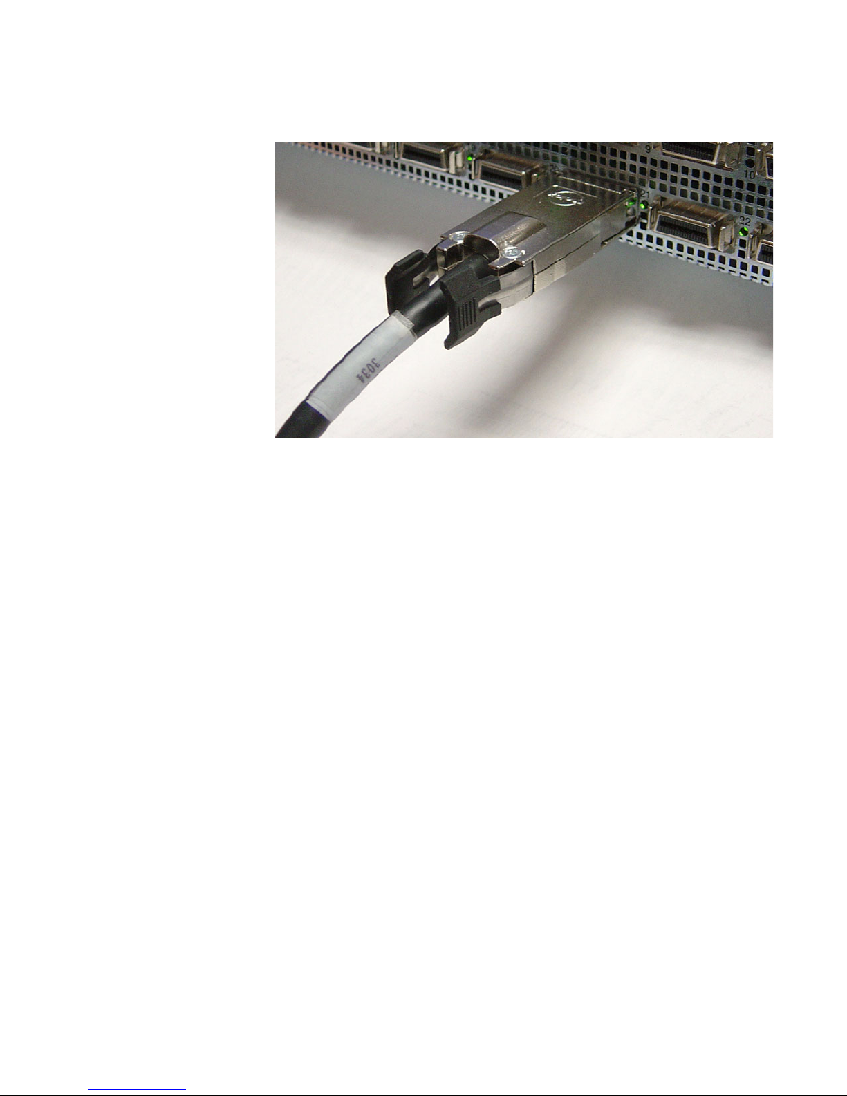
1. Plug InfiniBand cables from the host to the InfiniBand switch.
a. To plug in an InfiniBand cable, push the connector into the interface until you hear/feel a click.
Figure 2-2: Fully Installed IB Cable with Pinch Connector
13
Page 26
14
NOTE: If your host does not provide an ample amount of free space around a given IB port,
double-check that your IB cable connector engages fully. Wiggle your connector back and forth to be
sure that both sides of the connector have locked firmly into place.
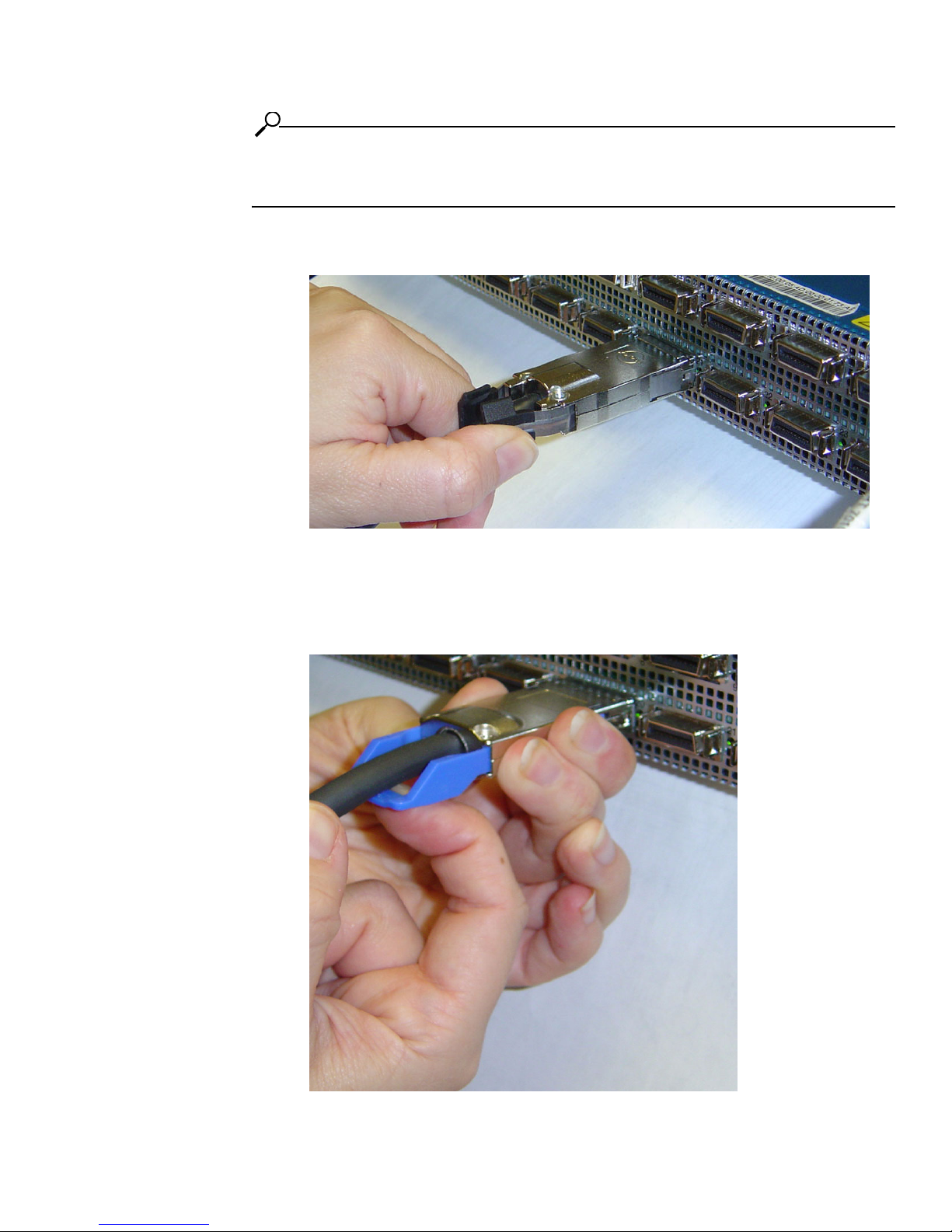
b. To remove a cable with a pinch connector, pinch both sides of the back of the connector and
pull the connector away from the port.
Figure 2-3: Removing a Pinch Connector
c. To remove a cable with a pull connector, grasp the connector with one hand and push it toward
the port, then pull the latch away from the port with your other hand and gently wiggle the
connector away from the port.
1. push connector toward port
2. pull latch away from port
3. pull connector away from port
Figure 2-4: Removing a Pull Connector
Page 27

Installing the HCA Drivers
This chapter provides the following information:
• “Installing HCA Host Drivers” on page 15.
• “Verify the HCA and Driver Installation” on page 18
• “Upgrading the Firmware on the HCA” on page 20
15
3
About the Installation
The driver suite is architected to work optimally as a group of drivers. Due to inter-driver dependencies,
it is recommended that you install all the drivers. If you use tsinstall as described, all drivers are
installed.
After the installation, you can move on to configuring the drivers of your choice.
• “Configuring IPoIB Drivers” on page 23
• “Configuring SDP Drivers” on page 35
• “Configuring MPI Drivers” on page 29
• “Configuring SRP Drivers” on page 41
• “Configuring uDAPL Drivers” on page 59
Installing HCA Host Drivers
To install HCA software:
1. Go to http://support.hp.com/
2. Select “Software & Driver downloads.”
3. On the Software & Driver Downloads page, enter your product name, then click the double arrow.
Page 28

16
# ./tsinstall
4. Install the software.
a. Unzip the tar file containing the software using gunzip.
b. Extract the software into a local directory using tar.
c. Change to the local directory.
d. In a terminal window, execute the command ./tsinstall to install the host drivers. This script
automatically detects the available kernel and installs the appropriate RPM packages.
This command does not require arguments. For example:
Example
NOTE: The HCA drivers are usually installed as an RPM package. However, you can individually
install the drivers, if you chose. To uninstall the HCA drivers, uninstall these packages.
If you uninstall then re-install the HCA drivers, you must reboot the host before accessing the
InfiniBand switch.
Note the log data displayed.
The following is a sample output of the tsinstall script. It lists the OS kernels discovered by the
installation program and installed HCA drivers. It also lists the OS kernels for which there are currently
no available host drivers.
[root@elrond]# ./tsinstall
The following kernels are installed, but do not have drivers available:
2.4.20-8.i686
The following installed packages are out of date and will be upgraded:
topspin-ib-mod-rh9-2.4.20-8smp-1.1.3-666.i686
The following packages will be installed:
topspin-ib-rh9-1.1.3-687.i686.rpm (libraries, binaries, etc)
topspin-ib-mod-rh9-2.4.20-8smp-1.1.3-687.i686 (drivers)
installing 100%
#############################################################################
############
Page 29

Note: tsinstall upgrades the firmware on the HCA if it is outdated.
installing 100%
#############################################################################
############
Upgrading HCA 0 to firmware v2.00.0000 build 0
New Node GUID = 0005ad0000001720
New Port1 GUID = 0005ad0000001721
New Port2 GUID = 0005ad0000001722
Programming Tavor Microcode... Flash Image Size = 309760
Failsafe
[===========================================================================]
Erasing
[===========================================================================]
Writing
[===========================================================================]
Verifying
[===========================================================================]
Flash verify passed!
5. You must reboot the host before using InfiniBand if either of the following scenarios occurred:
• the firmware was upgraded
• you uninstalled, then re-installed the firmware
6. (Optional) Verify the installation.
17
Example
[root@elrond]# rpm -qa | grep topspin
topspin-ib-rh9-1.1.3-687
topspin-ib-mod-rh9-2.4.20-8smp-1.1.3-687
[root@elrond]#
7. Refer to the HP website http://support.hp.com/ for driver updates.
Page 30

18
Verify the HCA and Driver Installation
Check the HCA
1. Check HCA information with the /usr/local/topspin/bin/vstat script.
Example A:
The following example shows two HCA ports are connected to the InfiniBand fabric:
a. Note the port field to determine the HCA port designations. Port 1 is assigned the ib0 network
interface. For 2-port HCAs, port 2 is assigned the ib1 network interface.
The status should be PORT_ACTIVE. If the status is PORT_INITIALIZE, wait a few seconds
and check again.
b. Note the hw_ver (i.e., hardware version) and fw_ver (i.e., firmware version) fields. Check with
HP Customer Support to determine the appropriate hardware and firmware versions for your
HCA.
[root@gandalf]# /usr/local/topspin/bin/vstat
1 HCA found:
hca_id=InfiniHost0
vendor_id=0x02C9
part_id=0x5A44
hw_ver=0xA1
fw_ver=0x200000000
num_phys_ports=2
port=1
port_state=PORT_ACTIVE
sm_lid=0x0001
port_lid=0x01f1
port_lmc=0x00
max_mtu=2048
gid_tbl_len=32
GID[ 0]= fe:80:00:00:00:00:00:00:00:05:ad:00:00:01:43:5d
port=2
port_state=PORT_ACTIVE
sm_lid=0x0001
port_lid=0x01f2
port_lmc=0x00
max_mtu=2048
gid_tbl_len=32
GID[ 0]= fe:80:00:00:00:00:00:00:00:05:ad:00:00:01:43:5e
Page 31

Example B:
The following example shows one HCA port is connected to the InfiniBand fabric:
[root@gandalf]# /usr/local/topspin/bin/vstat
1 HCA found:
hca_id=InfiniHost0
vendor_id=0x02C9
part_id=0x5A44
hw_ver=0xA1
fw_ver=0x200000000
num_phys_ports=2
port=1
port_state=PORT_ACTIVE
sm_lid=0x0001
port_lid=0x02b9
port_lmc=0x00
max_mtu=2048
gid_tbl_len=32
GID[ 0]= fe:80:00:00:00:00:00:00:00:05:ad:00:00:00:16:70
port=2
port_state=PORT_DOWN
sm_lid=0x0000
port_lid=0x02ba
port_lmc=0x00
max_mtu=2048
gid_tbl_len=32
GID[ 0]= fe:80:00:00:00:00:00:00:00:05:ad:00:00:00:16:71
19
Verify the HCA and Server Communication
2. Verify that the HCA is recognized by the server.
a. Enter the lspci command. Look for Mellanox PCI bridge and InfiniBand listings. If a Mellanox
PCI bridge is not displayed, re-seat the HCA in the slot.
Example
[root@gandalf]# lspci
…
02:01.0 PCI bridge: Mellanox Technology: Unknown device 5a46 (rev a0)
03:00.0 InfiniBand: Mellanox Technology: Unknown device 5a44 (rev a0)
Check the Modules
The modules running on the server provide the underlying drivers for the respective protocols and
subnet management.
Page 32

20
3. Check the modules running on the HCA server by using the lsmod command.
a. Look for modules like ts_udapl, ts_sdp, ts_ipoib, ts_ib_sa_client, etc.
Example
[root@enclus2 root]# lsmod
Module Size Used by Tainted: P
ts_srp_host 70936 0
ts_ib_dm_client 22780 0 [ts_srp_host]
ts_ib_useraccess 13252 0 (autoclean) (unused)
ts_sdp 152376 0 (autoclean) (unused)
ts_ib_useraccess_cm 15520 0 (autoclean) (unused)
ts_udapl 36904 0 (autoclean) (unused)
ts_ip2pr 28156 0 (autoclean) [ts_sdp ts_ib_useraccess_cm
ts_udapl]
ts_ipoib 57260 1 (autoclean) [ts_udapl ts_ip2pr]
lp 9220 0 (autoclean)
parport 39072 0 (autoclean) [lp]
autofs 13780 1 (autoclean)
nfs 96880 3 (autoclean)
lockd 60624 1 (autoclean) [nfs]
sunrpc 91996 1 (autoclean) [nfs lockd]
ts_ib_cm 58808 0 [ts_srp_host ts_sdp ts_ib_useraccess_cm]
ts_ib_sa_client 29440 0 [ts_srp_host ts_ib_dm_client ts_udapl
ts_ip2pr
ts_ipoib]
ts_ib_client_query 12644 0 [ts_srp_host ts_ib_dm_client ts_udapl
ts_ip2pr
ts_ipoib ts_ib_sa_client]
ts_kernel_poll 14360 0 [ts_ib_dm_client ts_sdp ts_ip2pr ts_ib_cm
ts_i
b_client_query]
ts_ib_mad 21132 0 [ts_ib_useraccess ts_ib_cm
ts_ib_client_query]
ts_ib_tavor 24452 0 (autoclean) [ts_ib_useraccess_cm]
mod_vapi 132288 0 (autoclean) [ts_ib_useraccess_cm ts_udapl
ts_i
<output truncated>
Verify the HCA Initialization
1. Run the dmesg command.
Look for a line towards the end of the dmesg output like “Mellanox Tavor Device Driver is
creating device InfiniHost0.”
There should be no error messages immediately following this line.
[root@gandalf]# dmesg
…
Mellanox Tavor Device Driver is creating device “InfiniHost0”
THH kernel module initialized successfully
Upgrading the Firmware on the HCA
When initially installing host drivers, the firmware is upgraded automatically, if needed. However, the
following procedure may be used to upgrade an HCA at a later time.
Page 33

Note: If you have a Boot Over IB license agreement, any HCA can be upgraded to become a bootable
HCA.
Determine the Card Type
1. Determine card hardware version by entering:
[root@test root]#/usr/local/topspin/sbin/tvflash –i
• The card type will be Jaguar (older), Cougar, Cougar Cub.
• The ASIC revision will be A0 or A1.
Output will be displayed from tvflash.
HCA #0: Found MT23108, Cougar, revision A0 (firmware autoupgrade)
Primary image is v2.00.0000 build 0, for hardware with label
'HCA.Cougar.A0'
Secondary image is v1.18.0000 build 0, for hardware with label
'HCA.Cougar.A0'
Upon installation of the host drivers, the firmware is automatically updated, if needed. However, if
you have outdated firmware on a previously installed HCA, proceed to the next step.
21
Upgrade the Firmware
2. Upgrade the firmware by executing the following script:
/usr/local/topspin/sbin/tvflash –h 0 ./share/fw-AA-BB-XX.YY.0000.bin
Where:
•“0” = the HCA number. “-h 0” specifies the HCA # 1. “-h 1” would specify the HCA # 2
• AA = the card type, which is Cougar in the following example
• BB = the ASIC revision, which is A0 or A1
• XX and YY = the revision of the firmware file
Example
/usr/local/topspin/sbin/tvflash –h 0 ./share/fw-cougar-a1-3.00.0002.bin
The example above shows a firmware upgrade on HCA #1, which has a Cougar ASIC, the revision
A0, and firmware file revision 1.18.
3. Repeat steps 1 - 2 on each HCA card.
4. Reboot the PC.
Page 34

22
Page 35

Configuring IPoIB Drivers
IPoIB must be installed before it can be configured. Refer to “Installing the HCA Drivers” on page 15.
• “Assign Interfaces to HCAs” on page 23
• “Create Interface Partitions” on page 25
• “Run an IPoIB Performance Test” on page 27
23
4
Assign Interfaces to HCAs
About Assigning Interface for Single HCAs
When you are installing a single HCA in a server, the possible interfaces for the HCA will be ib0 and
ib1.
About Assigning Interfaces for Multiple HCAs
When you are installing multiple HCAs in one server, the driver will keep numbering the ports
consecutively. For example, the ports on the second HCA would be interfaces ib2 and ib3.
To assign ib interfaces:
1. Use ifconfig to assign IP addresses to the ib0 and ib1 interfaces. These addresses work like any
other IP address on the system.
Syntax:
[root@test root]# /usr/local/topspin/sbin/ifconfig ib# ip addr netmask mask
• ib# is the HCA network interface getting the IP address. This may be either ib0 or ib1.
• IP addr is the IP address to assign the network interface.
• netmask is a mandatory keyword.
Page 36

24
• mask is the netmask for the IP address.
Example of Single HCA
[root@test root]# /usr/local/topspin/sbin/
[root@test root]# ifconfig ib0 192.168.0.0 netmask 255.255.255.0
#
[root@test root]# ifconfig ib1 192.168.0.1 netmask 255.255.255.0
Example of Two HCAs
[root@test root]# /usr/local/topspin/sbin/
[root@test root]# ifconfig ib0 192.168.0.0 netmask 255.255.255.0
#
[root@test root]# ifconfig ib1 192.168.0.1 netmask 255.255.255.0
#
[root@test root]# ifconfig ib2 192.168.0.2 netmask 255.255.255.0
#
[root@test root]# ifconfig ib3 192.168.0.3 netmask 255.255.255.0
The IPoIB driver is automatically started when the interface ports are accessed the first time. To
enable these drivers across reboots, you must explicitly add these settings to the networking
interface startup script.
Refer to your Linux Distribution documentation for additional information about configuring IP
addresses.
View all the Interfaces
To view all the interfaces that are currently configured, as well as interfaces that are available to be
configured, use the ifconfig -a command.
Interfaces that are configured will display the assigned address. Interfaces that are not configured will
appear, but will not have an address to display.
Page 37

[root@enclus2 root]# /usr/local/topspin/sbin/
[root@enclus2 root]# ifconfig -a
eth0 Link encap:Ethernet HWaddr 00:30:48:29:B9:FA
inet addr:10.3.0.11 Bcast:10.3.255.255 Mask:255.255.0.0
UP BROADCAST RUNNING MULTICAST MTU:1500 Metric:1
RX packets:1200029 errors:0 dropped:0 overruns:0 frame:0
TX packets:12095 errors:0 dropped:0 overruns:0 carrier:0
collisions:0 txqueuelen:1000
RX bytes:99263236 (94.6 Mb) TX bytes:1293346 (1.2 Mb)
Interrupt:54 Base address:0x3000 Memory:e8200000-e8220000
eth1 Link encap:Ethernet HWaddr 00:30:48:29:B9:FB
BROADCAST MULTICAST MTU:1500 Metric:1
RX packets:0 errors:0 dropped:0 overruns:0 frame:0
TX packets:0 errors:0 dropped:0 overruns:0 carrier:0
collisions:0 txqueuelen:1000
RX bytes:0 (0.0 b) TX bytes:0 (0.0 b)
Interrupt:55 Base address:0x3040 Memory:e8220000-e8240000
ib0 Link encap:Ethernet HWaddr D8:15:05:AE:F3:5A
inet addr:192.168.0.2 Bcast:192.168.0.255 Mask:255.255.255.0
UP BROADCAST RUNNING MULTICAST MTU:2044 Metric:1
RX packets:142 errors:0 dropped:0 overruns:0 frame:0
TX packets:21 errors:0 dropped:0 overruns:0 carrier:0
collisions:0 txqueuelen:128
RX bytes:16273 (15.8 Kb) TX bytes:1456 (1.4 Kb)
25
ib1 Link encap:Ethernet HWaddr 00:00:00:00:00:00
BROADCAST MULTICAST MTU:2044 Metric:1
RX packets:0 errors:0 dropped:0 overruns:0 frame:0
TX packets:0 errors:0 dropped:0 overruns:0 carrier:0
collisions:0 txqueuelen:128
RX bytes:0 (0.0 b) TX bytes:0 (0.0 b)
lo Link encap:Local Loopback
inet addr:127.0.0.1 Mask:255.0.0.0
UP LOOPBACK RUNNING MTU:16436 Metric:1
RX packets:52369 errors:0 dropped:0 overruns:0 frame:0
TX packets:52369 errors:0 dropped:0 overruns:0 carrier:0
collisions:0 txqueuelen:0
RX bytes:3314198 (3.1 Mb) TX bytes:3314198 (3.1 Mb)
[root@enclus2 root]#
Create Interface Partitions
About Dividing an Interface
The parent interface is the main IPoIB interface (ib0, ib1, ib2, etc.). However, subinterfaces can be
created to be associated with InfiniBand Partitions. The main interface has a Partition Key (p_key)
associated with it, which is always ff:ff, and the subinterface is optional. If the subinterface is not
specified, it defaults to the parent interface.
The partitions (p_keys) provide traffic isolation.
Page 38

26
Configuring a Subinterface
For traffic isolation, partitions must be created on:
• the interfaces on the HCA
• the ports for the InfiniBand server switch
Refer to the HP 24-Port 4x Fabric Copper Switch User Guide for information regarding partitions
on the IB switch.
1. Locate the ipoibcfg utility through the following path:
/usr/local/topspin/sbin
2. Create the new interface. Enter the
to add the subinterface, and the partition value that has been created on the InfiniBand switch:
ipoibcfg add
Example
[root@test root]# /usr/local/topspin/sbin/ipoibcfg add ib0 80:0b
A new interface ib0 80:0b is created.
3. Configure the new interface just as you would the parent interface.
a. Use ifconfig to assign IP addresses to the ib0 8:00b interface. These addresses work like any
other IP address on the system.
ifconfig ib# ip addr netmask mask
• ib# is the HCA network interface getting the IP address, such as ib0.80:0b.
• IP addr is the IP address to assign the network interface.
• netmask is a mandatory keyword.
• mask is the netmask for the IP address.
<parent interface> <p_key value>
ipoibcfg add
command, the parent interface to which you want
Example
[root@test root]# cd /usr/local/topspin/sbin/
[root@test sbin]# file ipoibcfg ib0 80:0b 192.168.0.0 netmask 255.255.255.0
4. Create partitions on the ports of the InfiniBand server switch, if you have not already done so.
Refer to the HP 24-Port 4x Fabric Copper Switch User Guide for information regarding partitions
on the IB switch.
Verify IPoIB Connectivity
Ping between two InfiniBand-enabled hosts over IPoIB to test IPoIB connectivity.
1. Log into an InfiniBand-enabled server.
2. Use the ping command to reach a second InfiniBand-enabled server.
Example
# ping -c 1 192.168.0.2
PING 192.168.0.2 (192.168.0.2) from 192.168.0.1 : 56(84) bytes of data.
64 bytes from 192.168.0.2: icmp_seq=0 ttl=64 time=154 usec
--- 192.168.0.2 ping statistics --1 packets transmitted, 1 packets received, 0% packet loss
round-trip min/avg/max/mdev = 0.154/0.154/0.154/0.000 ms
3. Refer to “IPoIB Performance vs Ethernet Using netperf” on page 70 for a sample IPoIB test plan.
Page 39

Deleting an Interface Partition
To delete a subinterface:
1. Enter the
subinterface, and the partition value that has been created on the InfiniBand switch:
ipoibcfg del
Example
[root@test root]# /usr/local/topspin/sbin/
-bash: /usr/local/topspin/sbin/: is a directory
# ipoibcfg del ib0 80:0b
ipoibcfg del
<parent interface> <p_key value>
command, the parent interface from which you want to delete the
Run an IPoIB Performance Test
Refer to “IPoIB Performance vs Ethernet Using netperf” on page 70.
27
Page 40

28
Page 41

Configuring MPI Drivers
MPI must be installed before it can be configured. Refer to “Installing the HCA Drivers” on page 15.
• “Configure MPI” on page 29
• “Configure SSH” on page 30
• “Edit PATH Variable” on page 31
• “Perform Bandwidth Test” on page 32
• “Perform Latency Test” on page 32
For more information about MPI, refer to “MPI” on page 2.
The following procedure describes steps that will simplify your use of MPI.
29
5
Configure MPI
Before you can rsh MPI, you must establish a SSH connection between two hosts so that you can run
commands between the nodes without a log-in or password.
Page 42

30
Configure SSH
To configure SSH between two hosts so that a connection does not require a password, perform the
following steps:
1. Log in to the host that you want to configure as the local host (hereafter, “host 1”). (The second
host serves as the remote host.)
Example
login: username
Password: password
Last login: Tue Aug 31 14:52:42 from 10.10.253.115
You have new mail.
[root@qa-bc1-blade4 root]#
2. Enter the ssh-keygen -t rsa command to generate a public/private RSA key pair. The CLI prompts
you for a folder in which to store the key.
Example
qa-bc1-blade4:~ # ssh-keygen -t rsa
Generating public/private rsa key pair.
Enter file in which to save the key (/root/.ssh/id_rsa):
3. Press the Enter key to store the key in the default directory (/root/.ssh). The CLI prompts you to
enter a password.
NOTE: Do not enter a password!
Example
Enter file in which to save the key (/root/.ssh/id_rsa):
Created directory '/root/.ssh'.
Enter passphrase (empty for no passphrase):
4. Press the Return key to bypass the password option. The CLI prompts you to re-enter the
password.
Example
Enter passphrase (empty for no passphrase):
Enter same passphrase again:
5. Press the Return key again (once again, omit a password). The CLI displays the fingerprint of the
host.
Example
Enter same passphrase again:
Your identification has been saved in /root/.ssh/id_rsa.
Your public key has been saved in /root/.ssh/id_rsa.pub.
The key fingerprint is:
0b:3e:27:86:0d:17:a6:cb:45:94:fb:f6:ff:ca:a2:00 root@qa-bc1-blade4
qa-bc1-blade4:~ #
Page 43

6. Move to the .ssh directory that you created.
Example
qa-bc1-blade4:~ # cd .ssh
qa-bc1-blade4:~/.ssh #
7. Copy the public key to a file.
Example
qa-bc1-blade4:~/.ssh # cp id_rsa.pub authorized_keys4
8. Log in to the host that you want to configure as the remote host (hereafter “host 2”).
Example
login: username
Password: password
Last login: Tue Aug 31 14:52:42 from 10.10.253.115
You have new mail.
[root@qa-bc1-blade5 root]#
31
9. Create a .ssh directory in the root directory in host 2.
Example
qa-bc1-blade5:~ # mkdir .ssh
10. Return to host 1 and copy the file from step 7 to the directory that you created in step 9.
Example
qa-bc1-blade4:~/.ssh # scp authorized_keys4 qa-bc1-blade5:/root/.ssh
11. Test your ssh connection.
Example
[root@qa-bc1-blade4 root]# ssh qa-bc1-blade5
Last login: Tue Aug 31 14:53:09 2004 from host
[root@qa-bc1-blade5 root]#
Edit PATH Variable
1. Establish rsh or ssh connections between two nodes so that you can run commands between a local
and remote node without a log-in or password (see “Configure SSH” on page 30).
2. Verify that you do not need to add the compiler to the PATH
3. Add, if required, the following paths to your environment PATH:
• /usr/local/topspin/mpi/mpich/bin
• /usr/local/topspin/bin
Page 44

32
NOTE: Optionally, you can add the paths for all users by adding
export PATH=$PATH:/usr/local/topspin/mpi/mpich/bin:/usr/local/topspin/bin to your
/etc/profile.d script.
4. Verify that your compiler and MPI script match. Compilers reside in the
/usr/local/topspin/mpi/mpich/bin directory. GNU compilers use mpicc and mpif77 scripts. Intel
compilers use mpicc.i and mpif90.i scripts.
Perform Bandwidth Test
Before you perform the bandwidth test, configure rsh or ssh on your hosts. To perform the test, perform
the following steps:
1. Log in to your local host.
2. Enter the mpirun_ssh (or mpirun_rsh) command with
• the -np keyword to specify the number of processes
• the number of processes (integer)
• the host name of the local host
• the host name of the remote host
• the mpi_bandwidth command
• the number of times to transfer the data (integer)
• the number of bytes to transfer (integer)
to perform the bandwidth test.
Example
[root@qa-bc1-blade2 root]# /usr/local/topspin/mpi/mpich/bin/mpirun_ssh -np 2 qabc1-blade2 qa-bc1-blade3 /usr/local/topspin/mpi/mpich/bin/mpi_bandwidth 1000
262144
The authenticity of host 'qa-bc1-blade2 (X.X.X.X)' can't be established.
RSA key fingerprint is 0b:57:f2:c9:dc:cb:ef:67:1c:51:3b:bf:58:8a:35:04.
Are you sure you want to continue connecting (yes/no)?
3. Enter yes at the prompt to connect to your remote host.
Example
Are you sure you want to continue connecting (yes/no)? yes
Warning: Permanently added 'qa-bc1-blade2,10.2.1.176' (RSA) to the list of known
hosts.
262144 241.250722
[root@qa-bc1-blade2 root]#
The output (in the example, 241.250722) represents available bandwidth, in MB/sec.
Perform Latency Test
Before you perform the bandwidth test, configure rsh or ssh on your hosts. To perform the test, perform
the following steps:
1. Log in to your local host.
2. Enter the mpiruh_ssh command with
Page 45

• the -np keyword to specify the number of processes
• the number of processes (integer)
• the host name of the local host
• the host name of the remote host
• the mpi_latency command
• the number of times to transfer the data (integer)
• the number of bytes to transfer (integer)
to run the latency test.
Example
[root@qa-bc1-blade2 root]# /usr/local/topspin/mpi/mpich/bin/mpirun_ssh -np 2 qabc1-blade2 qa-bc1-blade3 /usr/local/topspin/mpi/mpich/bin/mpi_latency 10000 1
1 6.684000
The output (in the example, 6.684000) represents the latency, in microseconds.
33
Page 46

34
Page 47

Configuring SDP Drivers
SDP must be installed before it can be configured. Refer to “Installing the HCA Drivers” on page 15.
• “Configure IPoIB Interfaces” on page 35.
• “Specify Connection Overrides” on page 35
• “Convert Sockets-Based Applications” on page 35
• “Run a Performance Test on SDP” on page 37
• “Sample Configuration - OracleNet™ Over SDP for Oracle 9i” on page 38
35
6
Configure IPoIB Interfaces
SDP uses the same IP addresses and interface names as IPoIB.
1. Configure the IPoIB IP interfaces, if you have not already done so (page 23).
Specify Connection Overrides
2. Use a text editor to open the libsdp.conf file (located in /usr/local/topspin/etc). This file defines
when to automatically use SDP instead of TCP. You may edit this file to specify connection
overrides.
Convert Sockets-Based Applications
3. Refer to “Converting Sockets-Based Applications to Use SDP” on page 36 for information on the
various conversion methods.
Page 48

36
Converting Sockets-Based Applications to Use
SDP
There are three ways to convert your sockets-based applications to use SDP instead of TCP, which are
described in the table below:
S
Table 6-1: SDP Conversion Information
Conversion
Type
Explicit/
source code
Explicit/
application
Method Required Action
Converts sockets to use
SDP based on application
source code.
This is useful when you
want full control from
your application when
using SDP.
Converts socket streams to
use SDP based on the
application environment.
1. Change your source code to use
AF_INET
•
1. Load the installed
following ways:
• Edit the
• Add the full path of the library into
2. Set the application environment to include AF_INET_SDP.
Example:
csh setenv AF_INET_SDP
when calling the socket ( ) system call.
AF_INET_SDP
/usr/local/topspin/include/sdp_sock.h
full path of the library you want to use and it will be
preloaded.
or
/etc/ld.so.preload
for every executable that is linked with
is defined in
libsdp_sys.so
LD_PRELOAD
AF_INET_SDP
library in one of the
environment variable. Set this to the
. The library will be preloaded
instead of
libc
.
sh AF_INET_SDP =1
export AF_INET_SDP
Page 49

Table 6-1: SDP Conversion Information
37
Conversion
Type
Automatic
Method Required Action
Converts socket streams
based upon destination
port, listening port, or
program name.
1. Load the installed
ways:
• Edit the
the full path of the library you want to use will cause it to be
preloaded.
or
• Add the full path of the library into
/etc/ld.so.preload
preloaded for every executable that is linked with
2. Configure the ports, IP addresses, or applications that explicitly
use SDP by editing the
a. locate
/usr/local/topspin/etc
libsdp.conf
b. Make the following modifications:
• Match on Destination Port
Syntax:
destination ip_addr
prefix_length
Example:
match
• Match on Listening Port
Syntax
listen
ip_addr[/prefix_length
_port
Example:
match listen *:5001
• Match on Program Name:
Syntax:
libsdp.so
LD_PRELOAD
library in one of the following
environment variable. Setting this to
. This will cause the library to be
libsdp.conf
file.
(located in
)
[/
][:
destination
start_port
192.168.1.0/24
[-
end_port
][:
start_port[-end
]]
match program program_name*
libc
.
]]
Run a Performance Test on SDP
To perform throughput and latency tests on SDP, refer to “SDP Performance vs IPoIB Using netperf” on
page 71.
This uses shell type globs.
db2*
matches on any
program with a name starting with
match on
ttcp
, etc.
Example:
match program db2*
For more information about how
AF_SDP
/usr/local/topspin/etc/libsdp.conf
sockets, please refer to
AF_INET
sockets are converted to
db2. t?p
.
would
Page 50

38
Sample Configuration - OracleNet™ Over SDP for
Oracle 9i
• “Sample Topology” on page 38
• “Configure the Application Server” on page 39
• “Configure the Database Server” on page 39
• “Set Up Non-IB Connections” on page 40
• “Troubleshoot the Configuration” on page 40
Performance Acceleration
By leveraging a Server Switch, it is very simple to accelerate the database to application tier through the
network by utilizing the SDP protocol between connected systems. While additional improvements can
be achieved by modifying the application tier client and/or database server connection code, this is not
necessary to enable much of the benefit that a database environment can achieve.
Overview
To accelerate application performance in database systems:
• an additional library is loaded for all binaries
• a configuration script is set up to focus the scope of the SDP acceleration to the appropriate
processes.
This needs to be done on both the application server and database server in the same way.
Sample Topology
The following example shows a single Database server attached to a single Application Server.
• The client communicates via Ethernet to InfiniBand gateway with the Application Server on the
10.10.1.50 IP address via normal TCP/IP communications.
• The Database and the Application Servers communicate via Ethernet to InfiniBand gateway on an
alternate 192.168.10.50 address via the SDP protocol.
Figure 6-1: Sample Topology Using SDP
Page 51

Configure the Application Server
Set up a Preload Script
1. Set up a preload script in order to load the SDP library for all programs.
# echo '/lib/libsdp.so' >> /etc/ld.so.preload
Add Configuration Lines to the SDP Initialization Script
2. Add the appropriate configuration lines to the SDP initialization script.
This sets the host to listen on port 1521 for SDP connections, and to use SDP for any outbound
connections targeted to port 1521 on a remote host. This also assumes that the Oracle server and
client are configured to connect on port 1521. Set this as appropriate to your environment.
Perform these changes on all clients and servers.
# echo 'match listen *:1521' >>
/usr/local/topspin/etc/libsdp.conf
# echo 'match destination *:1521' >>
/usr/local/topspin/etc/libsdp.conf
3. Restart any client or server processes, such as the listener process on the database server, and any
applications that leverage OracleNet for database connectivity on the application server.
39
Examine Configuration Files
4. View SDP connection information by examining the following two files:
/proc/topspin/sdp/conn_data
/proc/topspin/sdp/conn_main
These files should show you the connections coming over SDP. If there are no SDP connections,
these special files will only show header information. If SDP is enabled properly on the server, you
should see at least one connection in wait state on the server.
Configure the Database Server
Set up a Preload Script
1. Set up a preload script in order to load the SDP library for all programs.
# echo '/lib/libsdp.so' >> /etc/ld.so.preload
Add Configuration Lines to the SDP Initialization Script
2. Add the appropriate configuration lines to the SDP initialization script.
This sets the host to listen on port 1521 for SDP connections, and to use SDP for any outbound
connections targeted to port 1521 on a remote host. This also assumes that the Oracle server and
client are configured to connect on port 1521. Set this as appropriate to your environment.
Perform these changes on all clients and servers.
# echo 'match listen *:1521' >>
/usr/local/topspin/etc/libsdp.conf
# echo 'match destination *:1521' >>
/usr/local/topspin/etc/libsdp.conf
3. Restart any client or server processes, such as the listener process on the database server, and any
applications that leverage OracleNet for database connectivity on the application server.
Page 52

40
Examine Configuration Files
4. View SDP connection information by examining the following two files:
/proc/topspin/sdp/conn_data
/proc/topspin/sdp/conn_main
These files should show you the connections coming over SDP. If there are no SDP connections,
these special files will only show header information. If SDP is enabled properly on the server, you
should see at least one connection in wait state on the server.
Set Up Non-IB Connections
The above configuration assumes that all processes connecting on port 1521 are SDP processes.
Processes communicating over SDP need to connect to other processes using SDP; mismatches will not
work.
Configure Other Listeners
If you need to set up other connections to clients that are not InfiniBand-connected (not using SDP), you
could configure other listeners using port numbers not specified in the libsdp.conf file.
Refer to “Examine Configuration Files” on page 39.
Confine SDP Processes
As an alternative to configuring additional listeners, you could confine SDP to processes connecting
over the IPoIB subnet(s) defined over the InfiniBand fabric.
Troubleshoot the Configuration
A typo in the /etc/ld.so.preload file can cause glibc processes to fail.
If glibc processes should fail:
1. Clear out the /etc/ld.so.preload file using echo.
# echo “” > /etc/ld.so.preload
Page 53

Configuring SRP Drivers
SRP must be installed before it can be configured. Refer to “Installing the HCA Drivers” on page 15.
For more information about SRP, refer to “Socket Direct Protocol (SDP)” on page 2.
• “Auto-Mount SRP Devices” on page 41.
• “Verify Configurations from the Host” on page 41
• “Special Considerations” on page 44 (If you are using RHEL 3 and have a local SCSI drive, refer to
page 44).
• “SRP Sample Configuration” on page 45
41
7
Auto-Mount SRP Devices
Auto-mount SRP devices by putting them in /etc/fstab.
SRP LUNS are automatically configured when the system boots; no further configuration is required.
Note that any LUN changes of Fibre Channel storage requires a host reboot in order for the host to see
the changes.
Verify Configurations from the Host
Once you have configured your storage and the Fibre Channel Gateway, verify the gateway and the
storage configuration from the host.
Verify the SCSI Devices from the Host
The following example shows verification of an EMC CX200 configuration from the SRP host. For the
complete configuration example, refer to “Sample SRP/Storage Topology” on page 45.
Page 54

42
Verify SRP Functionality
To show the SCSI devices that are currently visible from the SRP host:
Example of CX200
# cat /proc/scsi/scsi
Attached devices:
Host: scsi0 Channel: 00 Id: 00 Lun: 00
Vendor: SEAGATE Model: ST336706LC Rev: 010A
Type: Direct-Access ANSI SCSI revision: 03
Host: scsi0 Channel: 00 Id: 01 Lun: 00
Vendor: SEAGATE Model: ST336706LC Rev: 010A
Type: Direct-Access ANSI SCSI revision: 03
Host: scsi2 Channel: 00 Id: 00 Lun: 00
Vendor: DGC Model: RAID 1 Rev: 0099
Type: Direct-Access ANSI SCSI revision: 04
Host: scsi2 Channel: 00 Id: 00 Lun: 01
Vendor: DGC Model: RAID 5 Rev: 0099
Type: Direct-Access ANSI SCSI revision: 04
Host: scsi2 Channel: 00 Id: 00 Lun: 02
Vendor: DGC Model: RAID 5 Rev: 0099
Type: Direct-Access ANSI SCSI revision: 04
a. Note the following LUNs are visible, but cannot be accessed, (which is appropriate for this
set-up).
Host: scsi2
Channel: 00
Id: 00
Lun: 00/01
b. Note the following LUN is the CX200 RAID-5 group, which is available to the IB host:
Host: scsi2
Channel: 00
Id: 00
Lun: 02
Verify the SCSI HCA Driver Information
The following examples show verification of an EMC CX200 configuration from the SRP host.
1. Verify the SCSI HCA driver instance information that is associated with the SRP driver:
Example of CX200
# cat /proc/scsi/srp/2
Topspin SRP Driver
Index Service Active Port GID
0 T10.SRP5006016810201173 fe:80:00:00:00:00:00:00:00:05:ad:00:00:01:29:81
IOC GUID
00:05:ad:00:00:01:1e:d8 64 256 255
Number of Pending Connections 0
Number of Active Connections 1
Number of Connections 1
srp_host: target_bindings=5006016810201173.0
Page 55

2. Reload the SRP host driver:
Example
/etc/init.d/ts_srp restart
3. Rescan the SRP targets:
Example
/usr/local/topspin/sbin/rescan-scsi-bus.sh
Host adapter 0 (aic79xx) found.
Host adapter 1 (aic79xx) found.
Host adapter 2 (srp) found.
Scanning for device 0 0 0 0 ...
OLD: Host: scsi0 Channel: 00 Id: 00 Lun: 00
Vendor: SEAGATE Model: ST336607LC Rev: 0006
Type: Direct-Access ANSI SCSI revision: 03
Scanning for device 0 0 6 0 ....
OLD: Host: scsi0 Channel: 00 Id: 06 Lun: 00
Vendor: SUPER Model: GEM318 Rev: 0
Type: Processor ANSI SCSI revision: 02
Scanning for device 0 0 6 9 ...
4. To perform a simple test to access the CX200:
43
Example
# dd if=/dev/sde of=/dev/null bs=1000k
5. To perform a more stressful sequence test:
Create a raw device corresponding to the CX200 RAID group:
Example
# raw /dev/raw/raw1 /dev/sde
- Testing
# dd if=/dev/raw/raw1 of=/dev/null bs=512k &
# dd if=/dev/raw/raw1 of=/dev/null bs=512k &
# dd if=/dev/raw/raw1 of=/dev/null bs=512k &
# dd if=/dev/raw/raw1 of=/dev/null bs=512k &
# dd if=/dev/raw/raw1 of=/dev/null bs=512k &
# dd if=/dev/raw/raw1 of=/dev/null bs=512k &
# dd if=/dev/raw/raw1 of=/dev/null bs=512k &
# dd if=/dev/raw/raw1 of=/dev/null bs=512k &
sar -b 1 0
Page 56

44
or
Example
[root@enclus2 root]# iostat
Linux 2.4.21-9.ELsmp
avg-cpu: %user %nice %sys %idle
0.02 0.00 0.02 99.96
Device: tps Blk_read/s Blk_wrtn/s Blk_read Blk_wrtn
dev8-0 0.48 0.44 4.49 492912 5028152
dev8-1 0.00 0.00 0.00 344 0
dev8-2 0.00 0.00 0.00 336 0
[root@enclus2 root]#
Observe the results.
6. Kill all dds when verification is complete.
Example
[root@enclus2 root]# pkill dd
[root@enclus2 root]#
Special Considerations
If you are using RHEL 3 and have a local SCSI drive, you must use the following process so that the
SRP driver can discover multiple LUNs in the correct order.
Scenario
1. Determine if your set-up requires the special procedure:
• You are running RHEL 3
• Your host has a local SCSI drive
• You have installed an InfiniBand HCA in your host
• You have installed the SRP protocol
• The SRP initiator is communicating with a target that has multiple LUNs (for example LUN 0
and LUN 1)
If the above description fits your scenario, the SRP driver will start and discover the LUNs.
However, it will discover only LUN 0. Use the steps below to discover the LUNs in the correct
order.
2. Rescan the SRP targets from the host to discover all the LUNs.
Note: If you have multiple targets with multiple LUNs, the LUNs will be discovered in the wrong
order. Instead of all the LUNs on one device being discovered first (LUN 0, LUN 1, etc), LUN 0 on
the first target will be discovered, then LUN 0 on the second target will be discovered.
Page 57

Follow Step 3 - Step 6 to correct the LUN discovery.
Example
/usr/local/topspin/sbin/rescan-scsi-bus.sh
Host adapter 0 (aic79xx) found.
Host adapter 1 (aic79xx) found.
Host adapter 2 (srp) found.
Scanning for device 0 0 0 0 ...
OLD: Host: scsi0 Channel: 00 Id: 00 Lun: 00
Vendor: SEAGATE Model: ST336607LC Rev: 0006
Type: Direct-Access ANSI SCSI revision: 03
Scanning for device 0 0 6 0 ....
OLD: Host: scsi0 Channel: 00 Id: 06 Lun: 00
Vendor: SUPER Model: GEM318 Rev: 0
Type: Processor ANSI SCSI revision: 02
Scanning for device 0 0 6 9 ...
3. Edit the /etc/modules.conf file.
[root@enclus3 root]# /etc/modules.conf
4. Add the following line to the directory:
45
# BEGIN TOPSPIN ##
options scsi_mod max_scsi_luns=255
...
5. Rebuild the Initial RAM disk (initrd)
[root@enclus3 etc]# cd initrd
[root@enclus3 initrd]# mkinitrd -v-f /boot/initrd-2.4.21-9.0.1.ELsmp.img
2.4.21-9.0.1.ELsmp
6. (Optional) If your Initial RAM disk (initrd) uses LILO as the bootloader, you must include the
following step. This is not necessary if your bootloader is grub.
[root@enclus3 initrd]# lilo -c
SRP Sample Configuration
The following sample configuration covers a complex storage solution.
Sample SRP/Storage Topology
The following sample includes the following elements:
• EMC CX200 storage
• Topspin 360 InfiniBand chassis with a Fibre Channel gateway
• REL3 host with a single InfiniBand HCA installed
The example uses Logical Volume Manager (LVM) based storage subsystem configuration.
Viewing the Storage Configuration
In this example, the CX200 configuration is displayed through the EMC Navisphere Management Suite.
Page 58

46
The service processor B is being used to access one RAID-5 group. RAID-5 group is exposed as LUN
2.
1. Note the following information:
a. The WWN that ends with 12:33:0F:D8:11
b. The LUN 2
Figure 7-1: Viewing the Storage Configuration with Navisphere
Viewing the SRP Host
The InfiniBand driver on the SRP host system should be installed by using the procedure provided in
“Installing HCA Host Drivers” on page 15.
2. Use vstat to view information on the SRP host.
From the information below, you can conclude the following:
• The Node GUID of the SRP host is 00:05:ad:00:00:01:29:80.
The node GUID is located in the GID field. The GUID is the last 8-bytes.
• The HCA port being used is Port 1
Page 59

Example
# /usr/local/topspin/bin/vstat
1 HCA found:
hca_id=InfiniHost0
vendor_id=0x02C9
part_id=0x5A44
hw_ver=0xA1
fw_ver=0x300000002
num_phys_ports=2
port=1
port_state=PORT_ACTIVE
sm_lid=0x0007
port_lid=0x000f
port_lmc=0x00
max_mtu=2048
gid_tbl_len=32
GID[ 0]= fe:80:00:00:00:00:00:00:
port=2
port_state=PORT_DOWN
sm_lid=0x0000
port_lid=0x0002
port_lmc=0x00
max_mtu=2048
gid_tbl_len=32
GID[ 0]= fe:80:00:00:00:00:00:00:00:05:ad:00:00:01:29:82
00:05:ad:00:00:01:29:81
47
View the Topology
In this example, the SRP host is connected to port 3 on the InfiniBand switch card of the Topspin 360.
Use the Element Manager’s Topology view to display the physical topology.
3. Launch Element Manager
4. Select InfiniBand -> To po logy.
5. Click OK to specify the number of switches that will appear in the Topology.
Page 60

48
The InfiniBand Topology appears.
Figure 7-2: Element Manager InfiniBand -> Topology View
Configure the Fibre Channel Gateway
The Fibre Channel gateway used in this example is the one in slot 11, although this particular Topspin
360 has several gateways installed.
The example shown here is for reference purposes and to help make sense of the SRP host configuration
procedure. It can also be used in troubleshooting the SRP host configuration.
Page 61

1. View the InfiniBand chassis with Element Manager.
49
Slot 11
Figure 7-3: Element Manager View of Topspin 360
2. Double-click the Fibre Channel gateway.
The Fibre Channel Port Properties window appears.
The figure below shows the fibre channel port properties. The fibre channel port is directly linked
to the CX200 storage, with no intermediate fibre channel switches.
Figure 7-4: Element Manager Detailed Port View
Page 62

50
3. View general information about the SRP host swclus6 with Element Manager.
a. Select Fibre Channel -> Storage Manager.
b. Click open the SRP Hosts folder from the left navigation bar.
c. Click on the swclus6 host. View the General tab.
Figure 7-5: Element Manager SRP Host Information
4. View information for the SRP targets.
a. Click open the Ta rgets folder from the left navigation bar.
This example shows the available LUNs that are configured for the SRP host swclus6. Note
that only the LUN that is visible via the SP-B of the CX200 (the last one in the figure) will be
accessible. This is the LUN that has the WWN ending with 0F:D8:11.
Page 63

The following SRP targets are visible through port of the fibre channel gateway in slot 11.
51
Figure 7-6: Element Manager - SRP Targets View
Verify Configurations from the Host
Once you have configured your storage and the Fibre Channel Gateway, verify the gateway and the
storage configuration from the host.
Verify the SCSI Devices from the Host
The following example shows verification of an EMC CX200 configuration from the SRP host.
Page 64

52
Verify SRP Functionality
To show the SCSI devices that are currently visible from the SRP host:
Example of CX200
# cat /proc/scsi/scsi
Attached devices:
Host: scsi0 Channel: 00 Id: 00 Lun: 00
Vendor: SEAGATE Model: ST336706LC Rev: 010A
Type: Direct-Access ANSI SCSI revision: 03
Host: scsi0 Channel: 00 Id: 01 Lun: 00
Vendor: SEAGATE Model: ST336706LC Rev: 010A
Type: Direct-Access ANSI SCSI revision: 03
Host: scsi2 Channel: 00 Id: 00 Lun: 00
Vendor: DGC Model: RAID 1 Rev: 0099
Type: Direct-Access ANSI SCSI revision: 04
Host: scsi2 Channel: 00 Id: 00 Lun: 01
Vendor: DGC Model: RAID 5 Rev: 0099
Type: Direct-Access ANSI SCSI revision: 04
Host: scsi2 Channel: 00 Id: 00 Lun: 02
Vendor: DGC Model: RAID 5 Rev: 0099
Type: Direct-Access ANSI SCSI revision: 04
a. Note the following LUNs are visible, but cannot be accessed, (which is appropriate for this
set-up).
Host: scsi2
Channel: 00
Id: 00
Lun: 00/01
b. Note the following LUN is the CX200 RAID-5 group, which is available to the swclus6:
Host: scsi2
Channel: 00
Id: 00
Lun: 02
Page 65

Verify the SCSI HCA Driver Information
The following examples show verification of an EMC CX200 configuration from the SRP host.
1. To verify the SCSI HCA driver instance information that is associated with the SRP driver:
Example of CX200
# cat /proc/scsi/srp/2
Topspin SRP Driver
Index Service Active Port GID
0 T10.SRP5006016810201173 fe:80:00:00:00:00:00:00:00:05:ad:00:00:01:29:81
IOC GUID
00:05:ad:00:00:01:1e:d8 64 256 255
Number of Pending Connections 0
Number of Active Connections 1
Number of Connections 1
srp_host: target_bindings=5006016810201173.0
53
2. To reload the SRP host driver:
Example
/etc/init.d/ts_srp restart
3. To rescan the SRP targets:
Example
/usr/local/topspin/sbin/rescan-scsi-bus.sh
4. To perform a simple test to access the CX200:
Example
# dd if=/dev/sde of=/dev/null bs=1000k
5. To perform a more stressful sequence test:
Create a raw device corresponding to the CX200 RAID group:
Example
# raw /dev/raw/raw1 /dev/sde
- Testing
# dd if=/dev/raw/raw1 of=/dev/null bs=512k &
# dd if=/dev/raw/raw1 of=/dev/null bs=512k &
# dd if=/dev/raw/raw1 of=/dev/null bs=512k &
# dd if=/dev/raw/raw1 of=/dev/null bs=512k &
# dd if=/dev/raw/raw1 of=/dev/null bs=512k &
# dd if=/dev/raw/raw1 of=/dev/null bs=512k &
# dd if=/dev/raw/raw1 of=/dev/null bs=512k &
# dd if=/dev/raw/raw1 of=/dev/null bs=512k &
sar -b 1 0
Page 66

54
or
Example
# iostat
Observe the results.
6. Kill all dds when verification is complete.
Example
# pkill dd
Configure the SRP Target
The following example shows a Logical Volume Manager (LVM) configuration of the SRP target
1. Wipe out the current partition table and re-read.
Example
root@swclus6 root]# dd if=/dev/zero of=/dev/sde bs=1k count=1
1+0 records in
1+0 records out
[root@swclus6 root]# blockdev --rereadpt /dev/sde
The following sequence has been tested with:
# rpm -qa | grep lvm
lvm-1.0.3-15
2. Run vgscan for the first time
Example
[root@swclus6 root]# vgscan
vgscan -- reading all physical volumes (this may take a while...)
vgscan -- “/etc/lvm tab” and “/etc/lvmtab.d” successfully created
vgscan -- WARNING: This program does not do a VGDA backup of your volume group
3. Prepare the physical volume
Example
# pvcreate /dev/sde
pvcreate -- physical volume “/dev/sde” successfully created
[root@swclus6 root]# pvdisplay /dev/sde
pvdisplay -- “/dev/sde” is a new physical volume of 181.18 GB
Page 67

4. Create the volume group
Example
[root@swclus6 root]# vgcreate cx200_vg_000 /dev/sde
vgcreate -- INFO: using default physical extent size 4 MB
vgcreate -- INFO: maximum logical volume size is 255.99 Gigabyte
vgcreate -- doing automatic backup of volume group “cx200_vg_000”
vgcreate -- volume group “cx200_vg_000” successfully created and activated
[root@swclus6 root]# vgdisplay
--- Volume group --VG Name cx200_vg_000
VG Access read/write
VG Status available/resizable
VG # 0
MAX LV 256
Cur LV 0
Open LV 0
MAX LV Size 255.99 GB
Max PV 256
Cur PV 1
Act PV 1
VG Size 181.17 GB
PE Size 4 MB
Total PE 46380
Alloc PE / Size 0 / 0
Free PE / Size 46380 / 181.17 GB
VG UUID qyp8s0-D8zb-ES8L-m6R4-iRcm-nPwF-FDA6ny
55
5. Create the file system
Example
[root@swclus6 root]# mkfs -t ext3 /dev/cx200_vg_000/swbld_lv
mke2fs 1.32 (09-Nov-2002)
Filesystem label=
OS type: Linux
Block size=4096 (log=2)
Fragment size=4096 (log=2)
23724032 inodes, 47448064 blocks
2372403 blocks (5.00%) reserved for the super user
First data block=0
1448 block groups
32768 blocks per group, 32768 fragments per group
16384 inodes per group
Superblock backups stored on blocks:
32768, 98304, 163840, 229376, 294912, 819200, 884736, 1605632, 2654208,
4096000, 7962624, 11239424, 20480000, 23887872
Writing inode tables: done
Creating journal (8192 blocks): done
Writing superblocks and filesystem accounting information: done
This filesystem will be automatically checked every 23 mounts or
180 days, whichever comes first. Use tune2fs -c or -i to override.
[root@swclus6 root]#
Page 68

56
6. View performance results taken during the mkfs
Example
IO pattern during the mkfs:
09:27:49 PM tps rtps wtps bread/s bwrtn/s
09:27:50 PM 0.00 0.00 0.00 0.00 0.00
09:27:51 PM 0.00 0.00 0.00 0.00 0.00
09:27:52 PM 5.05 5.05 0.00 40.40 0.00
09:27:53 PM 160.61 13.13 147.47 98.99 4149.49
09:27:53 PM tps rtps wtps bread/s bwrtn/s
09:27:54 PM 6457.14 0.00 6457.14 0.00 206653.06
09:27:55 PM 6735.90 2.56 6733.33 20.51 212748.72
09:27:56 PM 12516.67 0.00 12516.67 0.00 391566.67
09:27:57 PM 13010.53 0.00 13010.53 0.00 406400.00
09:27:58 PM 13721.05 0.00 13721.05 0.00 431157.89
09:27:58 PM tps rtps wtps bread/s bwrtn/s
09:27:59 PM 14482.35 0.00 14482.35 0.00 451694.12
09:28:00 PM 12747.62 0.00 12747.62 0.00 398171.43
09:28:01 PM 12952.63 0.00 12952.63 0.00 405452.63
09:28:02 PM 16187.50 0.00 16187.50 0.00 506787.50
09:28:02 PM tps rtps wtps bread/s bwrtn/s
09:28:03 PM 12680.00 0.00 12680.00 0.00 396910.00
09:28:04 PM 13110.00 0.00 13110.00 0.00 410560.00
09:28:05 PM 16833.33 0.00 16833.33 0.00 526293.33
09:28:06 PM 13445.00 0.00 13445.00 0.00 419940.00
09:28:07 PM 15966.67 0.00 15966.67 0.00 500977.78
09:28:07 PM tps rtps wtps bread/s bwrtn/s
09:28:08 PM 14817.65 0.00 14817.65 0.00 468141.18
09:28:09 PM 15629.41 0.00 15629.41 0.00 494494.12
09:28:10 PM 14682.35 0.00 14682.35 0.00 463247.06
09:28:11 PM 15305.88 0.00 15305.88 0.00 483400.00
09:28:11 PM tps rtps wtps bread/s bwrtn/s
09:28:12 PM 16037.50 0.00 16037.50 0.00 506662.50
09:28:13 PM 13621.05 0.00 13621.05 0.00 430084.21
09:28:14 PM 14288.89 0.00 14288.89 0.00 451211.11
09:28:15 PM 14366.67 0.00 14366.67 0.00 455033.33
09:28:15 PM tps rtps wtps bread/s bwrtn/s
09:28:16 PM 13510.53 0.00 13510.53 0.00 427021.05
09:28:17 PM 11795.45 0.00 11795.45 0.00 371927.27
09:28:18 PM 11269.23 0.00 11269.23 0.00 355184.62
09:28:19 PM 13331.58 0.00 13331.58 0.00 418873.68
09:28:20 PM 13235.00 0.00 13235.00 0.00 415840.00
09:28:20 PM tps rtps wtps bread/s bwrtn/s
09:28:21 PM 13652.63 0.00 13652.63 0.00 428126.32
09:28:22 PM 13484.21 0.00 13484.21 0.00 422557.89
09:28:23 PM 12857.14 0.00 12857.14 0.00 402447.62
09:28:24 PM 15431.25 0.00 15431.25 0.00 485000.00
<output truncated>
Page 69

7. Mount the file system
Example
[root@swclus6 root]# mount /dev/cx200_vg_000/swbld_lv /swbld
8. Verify that the configuration is still working.
Example
Full fsck:
[root@swclus6 /]# umount /swbld/
[root@swclus6 /]# fsck -f /dev/cx200_vg_000/swbld_lv
fsck 1.32 (09-Nov-2002)
e2fsck 1.32 (09-Nov-2002)
Pass 1: Checking inodes, blocks, and sizes
Pass 2: Checking directory structure
Pass 3: Checking directory connectivity
Pass 4: Checking reference counts
Pass 5: Checking group summary information
/dev/cx200_vg_000/swbld_lv: 54/23724032 files (0.0% non-contiguous),
752717/47448064 blocks
57
Page 70

58
9. View the actual SRP host configuration
a. Click into the swclus6 host in the left navigation bar.
b. Click the LUN Access tab.
Figure 7-7: Element Manager - Storage Manager View
c. Click onto one of the LUNs in the Accessible LUNs window.
d. Click the Edit ITL Properties button.
Figure 7-8: Element Manager - Storage Manager Edit ITL Properties
10. View the ITL properties. Assign a description, or set the Port Mask, if necessary.
Page 71

Configuring uDAPL Drivers
The uDAPL drivers must be installed before they can be configured. Refer to “Installing the HCA
Drivers” on page 15.
About the uDAPL Configuration
The User Direct Access Programming Library (uDAPL) protocol is transparently installed and requires
no further configuration. However, your application may require configuration for uDAPL. In addition,
you may want to run the Performance and Latency tests that are provided with the RPMs.
Refer to “uDAPL” on page 2 for information about the protocol
• “Building uDAPL Applications” on page 59
• “Run a uDAPL Performance Test” on page 60
59
8
Building uDAPL Applications
1. The User Direct Access Programming Library (uDAPL) protocol is transparently installed and
requires no further configuration.
2. Verify the application requirements:
a. Your application must support uDAPL. Please refer to your application documentation for
more information.
b. uDAPL applications must include udat.h (which is located in /usr/local/topspin/include/dat)
c. uDAPL applications must be linked against the libraries in /usr/local/topspin/lib
3. View sample make files and C code. See /usr/local/topspin/examples/dapl
Page 72

60
Run a uDAPL Performance Test
The utility to test uDAPL performance is included with the RPMs after the host-side drivers are
installed.
The uDAPL test utility is located in the following directory:
/usr/local/topspin/bin/
The uDAPL test must be run on a server and a client host.
Run a uDAPL Throughput Test
The Throughput test measures RDMA WRITE throughput using uDAPL.
1. Start the Throughput test on the server host.
Syntax for Server:
/usr/local/topspin/bin/thru_server.x <device_name> <RDMA size> <iterations> <batch size>
Example
[root@cdrom]# /usr/local/topspin/bin/thru_server.x ib0 262144 500 100
• ib0 is the name of the device
• 262144 is the size in bytes of the RDMA WRITE
• 500 is the numbers of RDMAs to perform for the test
• 100 is the number of RDMAs to perform before waiting for completions
2. Start the Throughput test on the client.
Syntax for Client:
/usr/local/topspin/bin/thru_client.x <server IP address> <RDMA size>
Example
[root@gcdrom]# /usr/local/topspin/bin/thru_server.x ib1 10.3.2.12 262144
• ib1 is the name of the device
• 10.3.2.12 is the IPoIB address of computer 1
• 262144 is the size in bytes of the RDMA WRITE
3. View the Throughput results.
Example
RDMA throughput server started on ib0
Created an EP with ep_handle = 0x8143718
queried max_recv_dtos = 256
queried max_request_dtos = 1024
Accept issued...
Received an event on ep_handle = 0x8143718
Context = 29a
Connected!
received rmr_context = bfb78 target_address = 80ea000 segment_length = 10000
Sent 6006.243 Mb in 1.0 seconds throughput = 6003.805 Mb/sec
Sent 6006.243 Mb in 1.0 seconds throughput = 6003.001 Mb/sec
Sent 6006.243 Mb in 1.0 seconds throughput = 6004.016 Mb/sec
Sent 6006.243 Mb in 1.0 seconds throughput = 6003.127 Mb/sec
Sent 6006.243 Mb in 1.0 seconds throughput = 6001.610 Mb/sec
total secs 5 throughput 6003 Mb/sec
Received an event on ep_handle = 0x8143718
Context = 29a
Page 73

Run a uDAPL Latency Test
The uDAPL Latency test measures the half of round-trip latency for uDAPL sends.
1. Start the Latency test on the server host.
Syntax for Server:
/usr/local/topspin/bin/lat_server.x <device_name> <RDMA size> <iterations> <batch size>
Example
[root@cdrom]# /usr/local/topspin/bin/lat_server.x ib0 150000 1 1
• ib0 is the name of the device
• 150000 is the numbers of RDMAs to perform for the test
• 1 is the size in bytes of the RDMA WRITE
• 1 is a flag specifying whether polling or event should be used. 0 signifies polling, and 1
signifies events.
2. Start the Latency test on the Client host.
Syntax for Client:
/usr/local/topspin/bin/lat_client.x <server IP address> <RDMA size>
Example
61
[root@gcdrom]# /usr/local/topspin/bin/lat_client.x ib1 10.3.2.12 150000 1 1
• ib1 is the name of the device
• 10.3.2.12 is the IPoIB address of computer 1 (server device)
• 150000 is the numbers of RDMAs to perform for the test
• 1 is the size in bytes of the RDMA WRITE
• 1 is a flag specifying whether polling or event should be used. 0 signifies polling, and 1
signifies events.
3. View the Latency results.
Example
Server Name: 10.3.2.12
Server Net Address: 10.3.2.12
Connection Event: Received the correct event
Latency: 29.0 us
Latency: 29.0 us
Latency: 28.5 us
Latency: 29.5 us
Latency: 29.5 us
Latency: 29.5 us
Latency: 29.0 us
Average latency: 29.1 us
Connection Event: Received the correct event
closing IA...
Exiting program...
Page 74

62
Page 75

Troubleshooting the HCA Installation
The following are a list of things you can check if the HCA does not operate appropriately.
• “Interpret HCA LEDs” on page 63
• “Check the InfiniBand Cable” on page 64
• “Check the InfiniBand Network Interfaces” on page 64
• “Run the HCA Self-Test” on page 65
63
9
Interpret HCA LEDs
There are two types of LEDs on the HCA card.
• The top yellow LED indicates a logical link has taken place.
• The bottom green LED indicates a physical link has occurred.
Figure 9-1: The HCA LEDs
Table 9-1: Interpreting the LEDs
LED Indication
Top LED Off indicates there is no logical link detected.
logical link status
physical link status
If this LED is Off, but the bottom LED is On, then a logical link error
has occurred. This indicates that the subnet manager has not done a
sweep.
Page 76

64
Table 9-1: Interpreting the LEDs
LED Indication
Top LED On indicates a logical link is detected. A logical link is established
when the subnet manager makes a sweep. A logical link must be
established if you are to use the port.
Bottom LED Off indicates that no physical link is detected. A physical link requires
that the drivers on the attached InfiniBand host have been installed and
are running.
Bottom LED On indicates that a physical link is detected.
Check the InfiniBand Cable
• Make sure an InfiniBand cable is connected to a port on the HCA and a port on the InfiniBand
switch card. HP recommends that you tug slightly on the cable to verify that is tightly connected as
poorly connected InfiniBand cables can cause errors that are difficult to detect.
• If you are running the Element Manager, click the Refresh button and note if the corresponding
InfiniBand port on the Element Manager turns green. If it’s green, you have a physical connection
and a logical link.
• Check the port LEDs on the HCA. The bottom LED should be green.
• Check the port LEDs on the InfiniBand switch. One should turn green, indicating a physical
connection is established.
• Note the port designations next to the HCA ports.
If you have one HCA installed in the host:
• Port 1 is assigned the ib0 network interface. Port 2 is assigned the ib1 network interface. If they
are not correctly connected, reconnect them.
If you have two HCAs installed in the host:
• ib0 is linked to port 1 of whichever HCA is discovered first in the system. You can run
/usr/local/topspin/bin/vstat and physically check which port reacts to the connection to
determine which HCA is first (ib0 and ib1). Refer to “Verify the HCA and Driver Installation”
on page 18.
Check the InfiniBand Network Interfaces
Check for InfiniBand network interfaces using the ifconfig -a command.
You should see interfaces that begin with ib (i.e., ib0, ib1).
Use the ifconfig -a command to display InfiniBand interfaces. If there are no ib0 and ib1 interfaces,
you may create them automatically or manually. To create them automatically each time the server
reboots, change the directory. The directory may be:
/etc/sysconfig/network-scripts.
Create one script per HCA port you wish to use (i.e., ifcfg-ib0, ifcfg-ib1). (You may copy another ifcfg
file, modify the DEVICE and IPADDR lines, then save it as either ifcfg-ib0 or ifcfg-ib1.)
To create it manually each time after booting the server, enter:
Syntax:
ifconfig ib# addr netmask mask
• ib# is the HCA network interface getting the IP address. This may be either ib0 or ib1.
Page 77

• addr is the IP address to assign the network interface.
• netmask is a mandatory keyword.
• mask is the netmask for the IP address.
Run the HCA Self-Test
The HCA Self-test verifies the state of the HCA component, the state of each port on the HCA, as well
as the connectivity to the fabric.
1. Log into the InfiniBand-enabled host.
2. Run the hca_self_test.
Example
[root@1750]# /usr/local/topspin/sbin/hca_self_test
Figure 9-2: Running the HCA Self-Test
Example
---- Performing InfiniBand HCA Self Test ----
Number of HCAs Detected ................ 1
PCI Device Check ....................... PASS
Host Driver Version .................... rhel3-2.4.21-4.ELsmp-2.0.0-530
Host Driver RPM Check .................. PASS
HCA Type of HCA #0 ..................... Cougar
HCA Firmware on HCA #0 ................. v3.01.0000
HCA Firmware Check on HCA #0 ........... PASS
Host Driver Initialization ............. PASS
Number of HCA Ports Active ............. 1
Port State of Port #0 on HCA #0 ........ UP
Port State of Port #1 on HCA #0 ........ DOWN
Error Counter Check .................... PASS
Kernel Syslog Check .................... PASS
------------------ DONE ---------------------
65
Figure 9-3: HCA Self-Test with Port Error
3. View the output of the HCA Self-test. In the example shown in Figure 9-3, port #1 of the HCA is
not properly connected.
4. View another example of the HCA Self-test. In the example shown in Figure 9-4, both ports on the
HCA appear to be disconnected, or are not connected properly.
The following errors appear:
• Port State of Port #0 on HCA #0 is Down
• Error Counters Failure
Page 78

66
Example
[root@1750]# /usr/local/topspin/sbin/hca_self_test
---- Performing InfiniBand HCA Self Test ----
Number of HCAs Detected ................ 1
PCI Device Check ....................... PASS
Host Driver Version .................... rhel3-2.4.21-4.ELsmp-2.0.0-530
Host Driver RPM Check .................. PASS
HCA Type of HCA #0 ..................... Cougar
HCA Firmware on HCA #0 ................. v3.01.0000
HCA Firmware Check on HCA #0 ........... PASS
Host Driver Initialization ............. PASS
Number of HCA Ports Active ............. 0
Port State of Port #0 on HCA #0 ........ DOWN
Port State of Port #1 on HCA #0 ........ DOWN
Error Counter Check .................... FAIL
REASON: found errors in the following counters
Errors in /proc/topspin/core/ca1/port1/counters
Symbol error counter: 29
Kernel Syslog Check .................... PASS
Figure 9-4: HCA Self-Test with Errors on Two Ports
5. To locate further information about an error counter failure, execute counters on a specific port.
Example
[root@1750]# cat /proc/topspin/core/ca1/port1/counters
Symbol error counter: 29
Link error recovery counter: 0
Link downed counter: 1
Port receive errors: 0
Port receive remote physical errors: 0
Port receive switch relay errors: 0
Port transmit discards: 2
Port transmit constrain errors: 0
Port receive constrain errors: 0
Local link integrity errors: 0
Excessive buffer overrun errors: 0
VL15 dropped: 0
Port transmit data: 1133136
Port receive data: 1099008
Port transmit packets: 15738
Port receive packets: 15264
Figure 9-5: Example of Error Counter Output
Page 79

Sample Test Plan
The following evaluation test plan will walk you through basic setup of the InfiniBand-based switching
fabric, introduce you to some of the ULPs (Upper Layer Protocols) supported on the fabric, and perform
some basic tests that showcase the fabric's performance.
Overview
67
10
• “Requirements” on page 67
• “Network Topology” on page 68
• “Host and Switch Setup” on page 68
• “IPoIB Setup” on page 69
• “IPoIB Performance vs Ethernet Using netperf” on page 70
• “SDP Performance vs IPoIB Using netperf” on page 71
Requirements
Prerequisites
This test plan requires basic knowledge of Linux administration, networking protocols, and network
administration. This test of basic functionality and performance of the system should be completed in 3
days or less.
Hardware and Applications
• A minimum of two x86-based servers are required for demonstrating some of the basic
functionality of the switch and the associated ULPs. To take advantage of the high throughput and
Page 80

68
low latency aspects of the fabric, a minimum of dual Xeon servers (in the neighborhood of 2.0
GHz) with 133Mhz PCI-X expansion busses are required.
• An Ethernet switch should be used to network the two servers together. This switch can be of any
speed, but a gigabit version will provide the best platform for comparing high performance
communication over Ethernet and InfiniBand.
• One host channel adapter is required for each server.
• A utility called netperf is also required for performance testing. The tool and more information can
be found by going to http://www.netperf.org,
RPM. Install the netperf server and client on both servers in the test setup.
Network Topology
The network diagram in Figure 10-1 illustrates the way two servers, a switch, and an Ethernet network
should be connected for basic testing.
Test Client
or by contacting your sales engineer for a pre-built
Host (Listener)
Figure 10-1: Sample Test Topology
Host and Switch Setup
For basic inter-fabric testing of the switch, no configuration is required on the switch itself; therefore,
configuration of the switch's management interface can be left for later.
• For instructions on installing the Host Channel Adapters (HCAs), please refer to “Installing the
Host Channel Adapter (HCA)” on page 5. This section will instruct you how to physically install
the HCAs into your servers.
• To install the ULP drivers, please read and follow the instructions in “Installing HCA Host Drivers”
on page 15.
Note: Do not continue on to configure the drivers after the installation, as this will be described
below to suit the appropriate environment.
Page 81

IPoIB Setup
69
About IPoIB
IPoIB (IP over InfiniBand) is simply that: IP packets running over the InfiniBand fabric. This protocol
is useful for testing connectivity into the fabric between two hosts, and also for taking advantage of the
high speed fabric for “legacy” applications that are written to communicate over IP.
The drawback to using IPoIB compared to standard Gigabit Ethernet is that the operating system must
do packet checksumming, whereas modern NIC cards usually offload this function to hardware.
Configuring IPoIB
Configuration of IPoIB is similar to configuring Ethernet interfaces under Linux except the interfaces
are called ibx (i.e. ib0, ib1, etc) instead of ethx (e.g. eth0, eth1, etc).
To test the IPoIB interfaces, choose a subnet that is currently not routed in your network environment.
For this test, we'll choose 192.168.0.0 with a netmask of 255.255.255.0 and assign “Server 1” the
address 192.168.0.1 and “Server 2” 192.168.0.2.
1. On Server 1, use ifconfig to configure ib0:
Example
# ifconfig ib0 192.168.0.1 netmask 255.255.255.0
2. Verify that the interface was configured properly:
Example
# ifconfig ib0
ib0 Link encap:Ethernet HWaddr 00:00:00:00:00:00
inet addr:192.168.0.1 Bcast:192.168.0.255 Mask:255.255.255.0
UP BROADCAST MTU:2044 Metric:1
RX packets:0 errors:0 dropped:0 overruns:0 frame:0
TX packets:3 errors:0 dropped:0 overruns:0 carrier:0
collisions:0 txqueuelen:128
RX bytes:0 (0.0 b) TX bytes:126 (126.0 b)
3. Repeat the process on Server 2 by configuring ib0 to 192.168.0.2.
If the system failed to configure the interface properly, you may not have successfully installed the
HCA drivers on the operating system. If the drivers did not install, it is likely due to a version
mismatch between the driver suite and the installed kernel.
4. To test connectivity, attempt to ping Server 2 from Server 1, using the ping command:
Example
# ping -c 1 192.168.0.2
PING 192.168.0.2 (192.168.0.2) from 192.168.0.1 : 56(84) bytes of data.
64 bytes from 192.168.0.2: icmp_seq=0 ttl=64 time=154 usec
--- 192.168.0.2 ping statistics --1 packets transmitted, 1 packets received, 0% packet loss
round-trip min/avg/max/mdev = 0.154/0.154/0.154/0.000 ms
If you do not receive a response from the other server, check cable connectivity. Be sure the
InfiniBand cable is plugged into the correct port for ib0 on the HCA (top port on the PCI adapter
card). Also, check the LEDs on both the HCA and the InfiniBand switch. Refer to “Interpret HCA
LEDs” on page 63.
Page 82

70
IPoIB Performance vs Ethernet Using netperf
To test the performance characteristics of IPoIB, use a tool called netperf. This utility runs on both
machines with one machine listening on a TCP socket and the other connecting and sending test data.
The listening program is called netserver while the test client is called netperf.
Netperf has many options, but this example just uses the basic TCP stream test for measurements.
1. Install the netperf utility on both the netperf server and client in the test setup.
For more information, refer to the requirements in “Hardware and Applications” on page 67.
2. Start the listener on Server 2:
Example
# netserver
Perform a Throughput Test
3. Develop a base case for comparison.
a. On Server 1, run netperf across a normal Ethernet interface.
b. For the output below, we used a cross-over cable between the two servers on their Gigabit
Ethernet interfaces:
c. The options entered into netperf mean the following:
• “-c” and “-C” - requests a report of the local and remote CPU utilization metrics
• “-f g” - requests a report of the results in gigabits per second
d. “-H 192.168.10.21” - specifies the host to contact for running the test
Example
# netperf -c -C -f g -H 192.168.10.21
4. Read the test results.
The sample results show about wire speed over the Gigabit Ethernet link, with around 20% CPU
utilization on both ends.
Example
TCP STREAM TEST to 192.168.10.21
Recv Send Send Utilization Service Demand
Socket Socket Message Elapsed Send Recv Send Recv
Size Size Size Time Throughput local remote local remote
bytes bytes bytes secs. 10^9bits/s % T % T us/KB us/KB
87380 16384 16384 10.00 0.94 19.10 23.70 1.662 2.062
5. Run the test over the IPoIB interface, which was previously setup.
# netperf -c -C -f g -H 192.168.0.2
TCP STREAM TEST to 192.168.0.2
Recv Send Send Utilization Service Demand
Socket Socket Message Elapsed Send Recv Send Recv
Size Size Size Time Throughput local remote local remote
bytes bytes bytes secs. 10^9bits/s % T % T us/KB us/KB
87380 16384 16384 10.01 1.21 33.88 87.35 2.290 5.905
The results in this example show about a 28% increase in throughput, but that has come at the
expense of higher CPU utilization on both the sender and receiver. This is because the native
Ethernet card does TCP/IP checksumming in hardware, while the IPoIB interface must use the host
CPU.
Page 83

Perform a Latency Test
To demonstrate the latency advantage of InfiniBand compared to Ethernet, use a netperf test called TCP
request/response. This test will send a 1 byte request to the remote machine and the remote machine will
issue a 1 byte response.
6. Develop a base case for comparison on Server 1. Add the -t TCP_RR option to the netperf
command to specify this test.
Example
# netperf -c -C -f g -H 192.168.10.21 -t TCP_RR
7. Read the results. The sample results show performance of about 5800 request/response transactions
per second.
Example
TCP REQUEST/RESPONSE TEST to 192.168.10.21
Local /Remote
Socket Size Request Resp. Elapsed Trans. CPU CPU S.dem S.dem
Send Recv Size Size Time Rate local remote local remote
bytes bytes bytes bytes secs. per sec % T % T us/Tr us/Tr
16384 87380 1 1 10.00 5787.80 4.50 7.30 7.775 12.619
71
8. Run the test over the InfiniBand interface on Server 1.
Example
netperf -c -C -f g -H 192.168.0.2 -t TCP_RR
TCP REQUEST/RESPONSE TEST to 192.168.0.2
Local /Remote
Socket Size Request Resp. Elapsed Trans. CPU CPU S.dem S.dem
Send Recv Size Size Time Rate local remote local remote
bytes bytes bytes bytes secs. per sec % T % T us/Tr us/Tr
16384 87380 1 1 10.00 11629.08 18.30 19.51 15.733 16.777
9. Compare the results. The IB interface shows about 11600 request/response transactions per second,
which is approximately double the performance of the gigabit Ethernet interface.
SDP Performance vs IPoIB Using netperf
About SDP
If you performed the steps in “IPoIB Performance vs Ethernet Using netperf” on page 70, you saw that
it's difficult to take advantage of the high bandwidth of InfiniBand using IPoIB without sacrificing the
CPU overhead associated with TCP/IP.
To solve the CPU overhead problem, the SDP (Sockets Direct Protocol) can be used over the fabric. The
SDP protocol sets up a reliable connection over the InfiniBand fabric, and TCP socket connections can
be made without the overhead of TCP. RDMA (Remote Direct Memory Access) semantics are used in
the protocol, which essentially transmits data between the two host's buffers without CPU intervention.
Configuring SDP
The decision to use this protocol rather than setting up a normal TCP socket is made at the kernel level.
Applications do not have to be re-written or re-compiled to take advantage of this capability. The
decision to use this protocol rather than setting up a normal TCP socket is made at the kernel level.
There are a variety of methods to control how connections are configured to use SDP, as documented in
/usr/local/topspin/etc/libsdp.conf.
Page 84

72
# killall netserver
# netserver.sdp
10. Make sure processes include the SDP library when they load.
The /etc/ld.so.preload file tells the system's dynamic linker to load the SDP library when processes
are started.
a. Create the /etc/ld.so.preload file if the file does not exist.
b. Add the following line to /etc/ld.so.preload on both systems:
/lib/libsdp_sys.so
11. Stop the existing netserver daemon, which expects TCP connections over a normal network socket.
a. Stop the netserver daemon on Server 2, using the killall command.
Example
Perform a Throughput Test
12. Tell the SDP library that the next process should use SDP, and start the netserver process on
Server 2:
Example
13. Run the netperf SDP Throughput test on Server 1.
Example
# netperf.sdp -c -C -f g -H 192.168.0.2
Recv Send Send Utilization Service Demand
Socket Socket Message Elapsed Send Recv Send Recv
Size Size Size Time Throughput local remote local remote
bytes bytes bytes secs. 10^9bits/s % T % T us/KB us/KB
65535 65535 65535 10.00 1.94 36.70 57.90 1.551 2.446
14. Read the test results.
The throughput has increased about 50% from using IPoIB, and the CPU utilization has been
significantly reduced.
Perform a Latency Test
In addition to the Throughput test, you can also test the effect of using SDP on the request/response test:
Example
# netperf.sdp -c -C -f g -H 192.168.0.2 -t TCP_RR
TCP REQUEST/RESPONSE TEST to 192.168.0.2
Local /Remote
Socket Size Request Resp. Elapsed Trans. CPU CPU S.dem S.dem
Send Recv Size Size Time Rate local remote local remote
bytes bytes bytes bytes secs. per sec % T % T us/Tr us/Tr
65535 65535 1 1 10.00 17145.82 15.00 17.10 8.747 9.976
In the example above, there is approximately a 50% increase in transactions per second from the
IPoIB case. In addition, there is a reduction in CPU utilization on both the transmit and receive end.
Page 85

Symbols
/etc/modules.conf ..................................................45
file system .............................................................55
firmware
upgrade ............................................................20
Numerics
133 MHz PCI-X
required speed ...................................................5
A
AF_INET_SDP .....................................................36
alloc .......................................................................55
B
Boot Over IB .........................................................21
C
cable connection ....................................................12
cables
remove ............................................................14
check for errors
dmesg ..............................................................20
configure
SDP .................................................................35
connect IB cables ..................................................12
cooling requirements ...........................................6, 7
counters .................................................................66
D
dapl
directory ..........................................................59
dds .........................................................................44
determine the HCA type .......................................21
diagnostic test .......................................................65
display IB interfaces .............................................64
dmesg ....................................................................20
drivers
install ...............................................................15
dual HCA installation .......................................7, 10
G
GID .................................................................18, 46
grounding methods to prevent electrostatic damage .
viii
grub .......................................................................45
GUID ..............................................................18, 46
H
hardware version ...................................................21
HCA initialization .................................................20
HCA self-test ........................................................65
HCA version .........................................................21
high profile installation ...........................................8
I
IB cable connection ..............................................12
ifconfig -a ........................................................24, 64
InfiniBand
LEDs ...............................................................63
InfiniBand partitions .............................................25
initial ram disk ......................................................45
initialization
dmesg ..............................................................20
initrd ......................................................................45
installation stability .............................................6, 7
iostat ......................................................................44
IPoIB
about ............................................................2, 69
configure for performance test ........................69
ITL properties .......................................................58
K
kernels
supported ...........................................................3
E
error counters ........................................................66
F
FCC notices
device modifications ....................................... vi
L
latency test
IPoIB ...............................................................71
SDP .................................................................72
uDAPL ............................................................60
LD_PRELOAD .....................................................37
LEDs
Page 86

Infiniband ........................................................63
LILO .....................................................................45
list of supported kernels ..........................................3
list of supported protocols .......................................1
Logical Volume Manager .....................................54
low profile installation ................................9, 11, 12
lsmod .....................................................................20
lspci .......................................................................19
Lun ........................................................................52
LVM ......................................................................54
M
remove IB cables ..................................................14
required speed .........................................................5
requirements
dual HCA install ...............................................7
rescan SRP targets ................................................43
restart ....................................................................43
RHEL 3
SRP .................................................................44
rpm -qa ..................................................................54
rpm -qa | grep lvm .................................................54
RPMs ....................................................................59
rsh ..........................................................................29
mkfs ......................................................................55
mkinitrd .................................................................45
module
verify ...............................................................20
MPI
about ..................................................................2
supported implementations ...............................2
N
netperf ...................................................................68
P
package contents .....................................................2
partition
about ................................................................25
delete ...............................................................27
PCI-Express
installing in a 1U host .....................................11
installing in a 2U+ host ...................................12
selecting the connector ......................................7
PCI-X slot ...............................................................6
performance test
IPoIB ...............................................................69
port mask ...............................................................58
power requirements .................................................5
protocols
supported ...........................................................1
R
S
sample topology
database cluster ...............................................38
sbin ........................................................................21
SCSI
show devices from SRP host ..........................52
verify HCA driver on drive .............................42
SCSI drive
local .................................................................44
SDP
about ..................................................................2
configure .........................................................35
performance test ..............................................71
vs IPoIB ..........................................................71
self-test
HCA ................................................................65
SRP
about ..................................................................2
configure .........................................................41
LUN discovery ................................................44
reload the SRP driver ......................................43
rescan targets ...................................................43
RHEL 3 ...........................................................44
Storage Manager .............................................58
target configuration .........................................54
Storage Manager ...................................................58
subinterface
about ................................................................25
configure .........................................................26
supported slots ........................................................5
RDMA
performance ....................................................60
performance test ..............................................60
RDMA thru_client.x .............................................60
regulatory compliance notices
device modifications ....................................... vi
T
TCP
convert to SDP ................................................36
TCP/IP checksumming .........................................70
throughput test
Page 87

IPoIB ...............................................................70
SDP .................................................................72
thru_server.x .........................................................60
tsinstall ..................................................................16
tvflash ....................................................................21
U
uDAPL
about ............................................................2, 59
application configuation .................................59
sample make files ............................................59
ULP
performance test ..............................................67
upgrading firmware ...............................................20
upper layer protocols
performance test ..............................................67
V
verify modules
lsmod ...............................................................20
vgscan ...................................................................54
vstat .................................................................18, 46
 Loading...