

Page 1
Troubleshooting Manual
For printer part removal and part number
information, see the Repair Manual.
LaserJet Pro MFP M227
M227fdw
www.hp.com/support/ljM203
www.hp.com/support/ljmfpM227
M203d
M203dn
M203dw
M227d
M227sdn
M227fdn
LaserJet Pro M203
Page 2

Page 3

HP LaserJet Pro M203 and HP LaserJet Pro
MFP M227
Troubleshooting Manual
Page 4

Copyright and License
Trademark Credits
© Copyright 2016 HP Development Company,
L.P.
Reproduction, adaptation, or translation without
prior written permission is prohibited, except as
allowed under the copyright laws.
The information contained herein is subject to
change without notice.
The only warranties for HP products and
services are set forth in the express warranty
statements accompanying such products and
services. Nothing herein should be construed as
constituting an additional warranty. HP shall not
be liable for technical or editorial errors or
omissions contained herein.
Edition 1, 11/2016
Microsoft®, Windows®, Windows® XP, and
Windows Vista® are U.S. registered trademarks
of Microsoft Corporation.
Page 5

Conventions used in this guide
TIP: Helpful hints or shortcuts.
Reinstallation tip: Reinstallation helpful hints, shortcuts, or considerations.
NOTE: Information that explains a concept or how to complete a task.
IMPORTANT: Information that help the user to avoid potential printer error conditions.
CAUTION: Procedures that the user must follow to avoid losing data or damaging the printer.
WARNING! Procedures that the user must follow to avoid personal injury, catastrophic loss of data, or
extensive damage to the printer.
ENWW iii
Page 6

iv Conventions used in this guide ENWW
Page 7

For additional service and support information
HP service personnel, go to the Service Access Work Bench (SAW) at http://sawpro.glb.itcs.hp.com.
Channel partners, go to HP Channel Services Network (CSN) at www.hp.com/partners/csn .
At these locations, find information on the following topics:
●
Install and configure
●
Printer specifications
●
Up-to-date control panel message (CPMD) troubleshooting
●
Solutions for printer issues and emerging issues
●
Remove and replace part instructions and videos
●
Service advisories
●
Warranty and regulatory information
Channel partners, access training materials in the HP University and Partner Learning Center at
https://content.ext.hp.com/sites/LMS/HPU.page.
To access HP PartSurfer information from any mobile device, go to http://partsurfermobile.hp.com/ or scan the
Quick Response (QR) code below.
ENWW v
Page 8

vi For additional service and support information ENWW
Page 9

Table of contents
1 Theory of operation .................................................................................................................................................................................. 1
Related documentation and software .................................................................................................................................. 2
Basic operation ......................................................................................................................................................................... 3
Sequence of operation ........................................................................................................................................ 4
Formatter-control system ...................................................................................................................................................... 5
Sleep delay ............................................................................................................................................................ 5
Printer job language (PJL) .................................................................................................................................. 5
Printer management language (PML) .............................................................................................................. 6
Control panel ........................................................................................................................................................ 6
Wireless ................................................................................................................................................................. 6
Low end data model (LEDM) overview ............................................................................................................. 6
Advanced control language (ACL) overview .................................................................................................... 6
CPU ......................................................................................................................................................................... 6
Input/output (I/O) ................................................................................................................................................. 6
USB .................................................................................................................................................... 6
USB hosts ......................................................................................................................................... 6
10/100 networking ......................................................................................................................... 6
Fax ..................................................................................................................................................... 7
Memory ............................................................................................................................................. 7
Firmware ...................................................................................................................... 7
Nonvolatile random access memory (NVRAM) ...................................................... 7
Flash memory ............................................................................................................. 7
Random access memory ........................................................................................... 7
HP Memory Enhancement technology (MEt) ......................................................... 7
Engine-control system ............................................................................................................................................................ 8
DC controller ......................................................................................................................................................... 9
Motor control ................................................................................................................................. 11
Fan control ..................................................................................................................................... 11
Low-voltage power supply .............................................................................................................................. 12
Overcurrent/overvoltage protection ......................................................................................... 14
Low-voltage power supply failure detection ...................................................... 14
High-voltage power supply ............................................................................................................................. 14
ENWW vii
Page 10

High-voltage power supply circuits ........................................................................................... 15
Fuser control ...................................................................................................................................................... 15
Fuser control functions ................................................................................................................ 17
Fuser heater protection ............................................................................................................... 18
Engine laser scanner system ............................................................................................................................................... 19
Laser scanner failure detection ...................................................................................................................... 20
Safety .................................................................................................................................................................. 20
Image-formation process ................................................................................................................................ 21
Step 1: Pre-exposure ................................................................................................................... 24
Step 2: Primary charging ............................................................................................................. 24
Step 3: Laser-beam exposure .................................................................................................... 25
Step 4: Development ................................................................................................................... 25
Step 5: Transfer ............................................................................................................................ 26
Step 6: Separation ........................................................................................................................ 27
Step 7: Fusing ................................................................................................................................ 27
Step 8: Drum cleaning .................................................................................................................. 28
Toner cartridges ................................................................................................................................................ 28
Design ............................................................................................................................................. 28
Engine pickup, feed, and delivery system .......................................................................................................................... 30
Sensors and switches ....................................................................................................................................... 32
Motors and solenoids ....................................................................................................................................... 33
Jam detection/prevention ................................................................................................................................ 33
Scanning and image capture system (MFP printers) ....................................................................................................... 36
Motor and sensors ............................................................................................................................................ 38
Document feeder system (MFP printers) ........................................................................................................................... 39
Document feeder simplex operation ............................................................................................................. 39
Fax functions and operation (fax models only) ................................................................................................................ 40
Computer and network security features ..................................................................................................... 40
PSTN operation .................................................................................................................................................. 40
Receive faxes when you hear fax tones ........................................................................................................ 40
Distinctive ring function .................................................................................................................................... 41
Set up the distinctive ring function ............................................................................................ 41
Fax by using voice over IP (VOIP) services ..................................................................................................... 41
The fax subsystem ............................................................................................................................................ 42
Fax card in the fax subsystem ........................................................................................................................ 42
Safety isolation ............................................................................................................................. 42
Safety-protection circuitry .......................................................................................................... 42
Data path ........................................................................................................................................ 42
Hook state ...................................................................................................................................... 43
Downstream device detection .................................................................................................... 43
Hook switch control ...................................................................................................................... 43
viii ENWW
Page 11

Ring detect ..................................................................................................................................... 43
Line current control ...................................................................................................................... 43
Billing or metering tone filters .................................................................................................... 44
Fax page storage in flash memory ................................................................................................................. 44
Stored fax pages ........................................................................................................................... 44
Advantages of flash memory storage ...................................................................................... 44
2 Solve problems ....................................................................................................................................................................................... 45
For additional service and support ...................................................................................................................................... 46
Troubleshooting process ...................................................................................................................................................... 47
Determine the problem source ....................................................................................................................... 47
Pre-troubleshooting checklist .................................................................................................... 47
Troubleshooting flowchart ......................................................................................................... 48
Power subsystem .............................................................................................................................................. 49
Power-on checks .......................................................................................................................... 49
Control panel checks ......................................................................................................................................... 49
Tools for troubleshooting ..................................................................................................................................................... 51
Individual component diagnostics .................................................................................................................. 51
Tools for troubleshooting: LED diagnostics ............................................................................. 51
Network LEDs (network models) ........................................................................... 51
Control-panel LEDs .................................................................................................. 51
Change the link speed setting (network models) ............................................... 52
Tools for troubleshooting: Engine diagnostics ........................................................................ 52
Engine test ................................................................................................................ 52
Diagrams ............................................................................................................................................................. 54
Diagrams: Block diagrams .......................................................................................................... 54
Sensors and switches (image formation system; printer base) ....................... 54
Cross section diagrams ........................................................................................... 56
Diagrams: Printed circuit assembly (PCA) connector locations ............................................ 59
Engine controller PCA .............................................................................................. 59
Formatter PCA .......................................................................................................... 60
Diagrams: External plug and port locations ............................................................................. 62
Diagrams: Locations of major components ............................................................................. 64
Major components (printer base) .......................................................................... 64
Diagrams: Timing chart ................................................................................................................ 65
Diagrams: Circuit diagrams ......................................................................................................... 67
Use advanced configuration with HP Embedded Web Server (EWS) and HP Device Toolbox
(Windows) ........................................................................................................................................................... 68
Internal test and information pages .............................................................................................................. 71
Print the configuration report ..................................................................................................... 72
Print a configuration report from an LED control panel (M203) ...................... 72
ENWW ix
Page 12

Print the configuration report from a 2-line control panel (M227) ................. 72
Print the configuration report from a touchscreen control panel (M227) ...... 72
Finding important information on the configuration report ............................. 73
Control panel menus ........................................................................................................................................ 76
Setup menu ................................................................................................................................... 76
HP Web Services menu ........................................................................................... 76
Reports menu ........................................................................................................... 77
Self Diagnostics menu ............................................................................................. 79
Fax Setup menu (fax models) ................................................................................ 79
System Setup menu ................................................................................................ 82
Network Setup menu .............................................................................................. 85
Quick Forms menu ................................................................................................... 86
Function specific menus .............................................................................................................. 88
Fax Menu (fax models) ............................................................................................ 88
Copy menu (MFP models) ....................................................................................... 89
Scan menu (MFP models) ....................................................................................... 91
USB menu (MFP models) ........................................................................................ 91
Apps ............................................................................................................................ 91
Supplies ..................................................................................................................... 91
Control panel message document (CPMD) ................................................................................................... 92
Control-panel message types .................................................................................................... 92
Control-panel messages and event log entries ...................................................................... 92
Control Panel Error Messages (M203d/dn/dw, M206dn models) ................... 92
Control Panel Error Messages (M227d/sdn/fdn/fdw, M230sdn/fdw
models) ...................................................................................................................... 98
Tools for troubleshooting: Event log messages ................................................................... 114
Print an event log ................................................................................................... 114
View the event log ................................................................................................. 115
Improve print quality ........................................................................................................................................................... 117
Print from a different software program .................................................................................................... 117
Check the paper-type setting for the print job ........................................................................................... 117
Check the paper type setting (Windows) ................................................................................ 117
Check the paper type setting (OS X) ........................................................................................ 118
Check toner-cartridge status (M203) .......................................................................................................... 118
Check toner-cartridge status (M227) .......................................................................................................... 118
Print a cleaning page (M203) ........................................................................................................................ 119
Print a cleaning page (M227) ........................................................................................................................ 120
Check the scanner glass for dirt and smudges (M227) ............................................................................ 121
Visually inspect the toner cartridge or cartridges ..................................................................................... 121
Check paper and the printing environment ................................................................................................ 121
Step one: Use paper that meets HP specifications ............................................................... 121
x ENWW
Page 13

Step two: Check the environment ........................................................................................... 122
Step three: Set the individual tray alignment (M203) .......................................................... 122
Step three: Set the individual tray alignment (M227) .......................................................... 123
Try a different print driver ............................................................................................................................. 124
Check the EconoMode settings ..................................................................................................................... 125
Adjust print density (M203) ........................................................................................................................... 125
Adjust print density (M227) ........................................................................................................................... 126
Print quality troubleshooting guide .................................................................................................................................. 127
Image defects table ........................................................................................................................................ 127
Printer-specific image defects ...................................................................................................................... 134
Repetitive image defect ruler ................................................................................................... 134
Use a ruler to measure between repetitive defects ........................................ 135
Print quality troubleshooting guide ........................................................................................ 138
OPC short ................................................................................................................ 139
White blotches at low temperature .................................................................... 140
OPC drum ghost ..................................................................................................... 141
Toner block contamination on the exit roller .................................................... 142
Cartridge coupling defect (1 of 2) ....................................................................... 143
Cartridge coupling defect (2 of 2) ....................................................................... 144
Toner contamination ............................................................................................. 145
Sharp vertical streaks ........................................................................................... 146
Improve copy and scan image quality (M227) ................................................................................................................ 147
Introduction ...................................................................................................................................................... 147
Check the scanner glass for dirt and smudges .......................................................................................... 147
Check the paper settings ............................................................................................................................... 148
Optimize for text or pictures ......................................................................................................................... 149
Edge-to-edge copying ................................................................................................................................... 150
Clean the pickup rollers and separation pad in the document feeder ................................................... 150
Clean the printer .................................................................................................................................................................. 152
Print a cleaning page (M203) ........................................................................................................................ 152
Print a cleaning page (M227) ........................................................................................................................ 152
Clean the pickup roller and separation pad ................................................................................................ 153
Clean the pickup rollers and separation pad in the document feeder ................................................... 155
Check the scanner glass and white backing for dirt or smudges (M227) .............................................. 156
Clean the ADF replaceable film assembly (M227) ..................................................................................... 157
Clean the touchscreen (M227) ...................................................................................................................... 159
Solve paper-handling problems ....................................................................................................................................... 160
Printer feeds incorrect page size .................................................................................................................. 160
Printer pulls from incorrect tray ................................................................................................................... 160
Printer will not duplex or duplexes incorrectly .......................................................................................... 160
Paper does not feed from the input tray .................................................................................................... 160
ENWW xi
Page 14

Output is curled or wrinkled .......................................................................................................................... 161
Printer does not pick up paper or misfeeds ............................................................................................... 161
The printer does not pick up paper ......................................................................................... 161
The printer picks up multiple sheets of paper ....................................................................... 162
The document feeder jams, skews, or picks up multiple sheets of paper (MFP
models) ........................................................................................................................................ 162
Paper does not feed automatically ......................................................................................... 162
Clear paper jams (M203, M206) ................................................................................................................... 163
Introduction ................................................................................................................................. 163
Paper path jam sensor locations (M203) ............................................................................... 163
Jam locations .............................................................................................................................. 164
Experiencing frequent or recurring paper jams? ................................................................... 165
Clear jams in the Main input tray ............................................................................................. 166
Clear jams in the toner-cartridge area .................................................................................... 170
Clear jams in the output bin ...................................................................................................... 174
Clear jams in the duplexer ........................................................................................................ 176
Clear paper jams (M227, M230) ................................................................................................................... 179
Introduction ................................................................................................................................. 179
Paper path jam sensor locations (M227) ............................................................................... 180
Jam locations .............................................................................................................................. 182
Experiencing frequent or recurring paper jams? ................................................................... 182
Clear jams in the document feeder ......................................................................................... 184
Clear jams in the Main input tray ............................................................................................. 187
Clear jams in the toner-cartridge area .................................................................................... 170
Clear jams in the output bin ...................................................................................................... 174
Clear jams in the duplexer ........................................................................................................ 176
Solve performance problems ............................................................................................................................................ 203
Solve connectivity problems .............................................................................................................................................. 204
Solve USB connection problems .................................................................................................................. 204
Solve wired network problems ..................................................................................................................... 204
Introduction ................................................................................................................................. 204
Poor physical connection .......................................................................................................... 204
The computer is using the incorrect IP address for the printer .......................................... 204
The computer is unable to communicate with the printer .................................................. 205
The printer is using incorrect link speed and duplex settings for the network ................ 205
New software programs might be causing compatibility problems ................................. 205
The computer or workstation might be set up incorrectly .................................................. 205
The printer is disabled, or other network settings are incorrect ........................................ 205
Solve wireless network problems (M203, M206)) ..................................................................................... 205
Introduction ................................................................................................................................. 206
Wireless connectivity checklist ................................................................................................. 206
xii ENWW
Page 15

The printer does not print after the wireless configuration completes ............................ 206
The printer does not print, and the computer has a third-party firewall installed ......... 207
The wireless connection does not work after moving the wireless router or printer .... 207
Cannot connect more computers to the wireless printer .................................................... 207
The wireless printer loses communication when connected to a VPN ............................. 207
The network does not appear in the wireless networks list ............................................... 207
The wireless network is not functioning ................................................................................ 207
Perform a wireless network diagnostic test .......................................................................... 208
Reduce interference on a wireless network .......................................................................... 208
Solve wireless network problems (M227, M230) ...................................................................................... 209
Introduction ................................................................................................................................. 209
Wireless connectivity checklist ................................................................................................. 209
The printer does not print after the wireless configuration completes ............................ 210
The printer does not print, and the computer has a third-party firewall installed ......... 210
The wireless connection does not work after moving the wireless router or printer .... 210
Cannot connect more computers to the wireless printer .................................................... 210
The wireless printer loses communication when connected to a VPN ............................. 211
The network does not appear in the wireless networks list ............................................... 211
The wireless network is not functioning ................................................................................ 211
Perform a wireless network diagnostic test .......................................................................... 211
Reduce interference on a wireless network .......................................................................... 212
Service mode functions ...................................................................................................................................................... 213
Service menu (M227) ..................................................................................................................................... 213
Secondary service menu ................................................................................................................................ 215
Printer resets ................................................................................................................................................... 217
Restore the factory-set defaults (M203) ............................................................................... 217
Restore the factory-set defaults (M227) ............................................................................... 218
NVRAM initialization ................................................................................................................... 219
Super NVRAM initialization ........................................................................................................ 219
Solve fax problems (fax models only) ............................................................................................................................. 221
Checklist for solving fax problems ............................................................................................................... 221
Solve general fax problems .......................................................................................................................... 222
Faxes are sending slowly .......................................................................................................... 222
Print quality of a photo is poor or prints as a gray box. ....................................................... 223
Fax quality is poor ...................................................................................................................... 223
Fax cuts off or prints on two pages ......................................................................................... 224
You touched the Cancel button to cancel a fax, but the fax was still sent .................. 224
No fax address book button displays ..................................................................................... 224
Not able to locate the fax settings in HP Web Jetadmin ...................................................... 225
The header is appended to the top of the page when the overlay option is enabled .... 225
A mix of names and numbers is in the recipients box .......................................................... 225
ENWW xiii
Page 16

A one-page fax prints as two pages ....................................................................................... 225
A document stops in the document feeder in the middle of faxing .................................. 225
The volume for sounds coming from the fax accessory is too high or too low .............. 225
Use fax over VoIP networks ...................................................................................................... 225
Solve problems receiving faxes .................................................................................................................... 226
Solve problems sending faxes ...................................................................................................................... 230
Fax error messages on the control panel ................................................................................................... 231
The No Fax Detected message displays ................................................................................. 231
The Communication error message appears ........................................................................ 231
No Dial Tone ................................................................................................................................ 232
The Fax is busy message appears ........................................................................................... 233
The No fax answer message appears ..................................................................................... 233
Document feeder paper jam .................................................................................................... 234
The Fax storage is full message appears ............................................................................... 234
Scanner error .............................................................................................................................. 234
The control panel displays a Ready message with no attempt to send the fax .............. 234
The control panel displays the message "Storing page 1" and does not progress
beyond that message ................................................................................................................ 234
Faxes can be received, but not sent ........................................................................................ 235
Printer is password protected .................................................................................................. 235
Unable to use fax functions from the control panel ............................................................ 235
Unable to use speed dials ......................................................................................................... 235
Unable to use group dials ......................................................................................................... 236
Receive a recorded error message from the phone company when trying to send a
fax ................................................................................................................................................. 236
Unable to send a fax when a phone is connected to the printer ........................................ 237
Troubleshoot fax codes and trace reports ................................................................................................. 237
View and interpret fax error codes .......................................................................................... 237
Fax trace report .......................................................................................................................... 238
Fax logs and reports ....................................................................................................................................... 238
Print all fax reports .................................................................................................................... 238
Print individual fax reports ........................................................................................................ 238
Set the fax error report ............................................................................................................. 239
Set the fax-error-correction mode .............................................................................................................. 239
Change the fax speed ..................................................................................................................................... 239
Use fax on a DSL, PBX, or ISDN system ....................................................................................................... 240
DSL ................................................................................................................................................ 240
PBX ............................................................................................................................................... 240
ISDN .............................................................................................................................................. 240
Solve email problems (M129/M134) ................................................................................................................................ 241
Cannot connect to the email server ............................................................................................................. 241
xiv ENWW
Page 17

Validate the SMTP gateway (Windows) ....................................................................................................... 241
Validate the LDAP gateway (Windows) ....................................................................................................... 241
Update the firmware ........................................................................................................................................................... 242
Method one: Update the firmware using the control panel (M227) ....................................................... 242
Method two: Update the firmware using the Firmware Update Utility (M203 and M227) ................. 243
Appendix A Printer specifications ......................................................................................................................................................... 245
Printer dimensions (M203) ................................................................................................................................................ 246
Printer dimensions (M227) ................................................................................................................................................ 247
Printer space requirements ............................................................................................................................................... 248
Power consumption, electrical specifications, and acoustic emissions ..................................................................... 248
Operating environmental range ........................................................................................................................................ 249
Certificates of volatility ....................................................................................................................................................... 250
Index ........................................................................................................................................................................................................... 255
ENWW xv
Page 18

xvi ENWW
Page 19

List of tables
Table 1-1 Sequence of operation ........................................................................................................................................................... 4
Table 1-2 Motors ..................................................................................................................................................................................... 11
Table 1-3 Fans ......................................................................................................................................................................................... 11
Table 1-4 List of DC voltages ................................................................................................................................................................ 13
Table 1-5 Fuser components ................................................................................................................................................................ 16
Table 1-6 Fuser control functions ........................................................................................................................................................ 17
Table 1-7 Sensors ................................................................................................................................................................................... 22
Table 1-8 Image formation process .................................................................................................................................................... 23
Table 1-9 Toner cartridge functions .................................................................................................................................................... 29
Table 1-10 Pickup, feed, and delivery system functions ................................................................................................................. 30
Table 1-11 Photo sensors and switches ............................................................................................................................................. 32
Table 1-12 Motors and solenoids ........................................................................................................................................................ 33
Table 1-13 Jams that the printer detects ........................................................................................................................................... 34
Table 1-14 Motor and sensors ............................................................................................................................................................. 38
Table 2-1 Troubleshooting flowchart ................................................................................................................................................. 48
Table 2-2 Sensors and switches (image formation system; printer base) ................................................................................... 54
Table 2-3 Sensors (pickup, feed, and delivery system; printer base) ............................................................................................ 55
Table 2-4 Service parts (cross section; printer base) ........................................................................................................................ 56
Table 2-5 Motor (cross section; printer base) .................................................................................................................................... 58
Table 2-6 Engine controller PCA connectors ..................................................................................................................................... 59
Table 2-7 Formatter PCA (M203) ......................................................................................................................................................... 60
Table 2-8 Formatter PCA (M227) ......................................................................................................................................................... 61
Table 2-9 External plug and port locations (M203) .......................................................................................................................... 62
Table 2-10 External plug and port locations (M227) ........................................................................................................................ 62
Table 2-11 Main assemblies ................................................................................................................................................................. 64
Table 2-12 Main parts (printer base) ................................................................................................................................................... 65
Table 2-13 PCAs (printer base) ............................................................................................................................................................. 65
Table 2-14 M203 sample configuration report ................................................................................................................................. 73
Table 2-15 M227 sample configuration report (first page) ............................................................................................................. 74
Table 2-16 M227 sample configuration report (second page) ....................................................................................................... 75
Table 2-17 HP Web Services menu ...................................................................................................................................................... 76
Table 2-18 Reports menu ..................................................................................................................................................................... 77
ENWW xvii
Page 20

Table 2-19 Self Diagnostics menu ....................................................................................................................................................... 79
Table 2-20 Fax Setup menu .................................................................................................................................................................. 79
Table 2-21 System Setup menu .......................................................................................................................................................... 82
Table 2-22 Network Setup menu ......................................................................................................................................................... 85
Table 2-23 Quick Forms menu ............................................................................................................................................................. 86
Table 2-24 Fax Menu .............................................................................................................................................................................. 88
Table 2-25 Copy menu ........................................................................................................................................................................... 90
Table 2-26 Scan menu ........................................................................................................................................................................... 91
Table 2-27 USB Menu ............................................................................................................................................................................. 91
Table 2-28 Status-light legend ............................................................................................................................................................ 92
Table 2-29 Primary control-panel light patterns .............................................................................................................................. 92
Table 2-30 Secondary control-panel light patterns ......................................................................................................................... 94
Table 2-31 Image defects table quick reference ............................................................................................................................ 127
Table 2-32 Light print .......................................................................................................................................................................... 129
Table 2-33 Gray background or dark print ....................................................................................................................................... 129
Table 2-34 Blank page — No print .................................................................................................................................................... 130
Table 2-35 Black page ......................................................................................................................................................................... 130
Table 2-36 Banding defects ............................................................................................................................................................... 131
Table 2-37 Streak defects .................................................................................................................................................................. 131
Table 2-38 Fixing/fuser defects ......................................................................................................................................................... 132
Table 2-39 Image placement defects ............................................................................................................................................... 132
Table 2-40 Color plane registrations defects (color models only) .............................................................................................. 133
Table 2-41 Output defects .................................................................................................................................................................. 133
Table 2-42 Repetitive defects ............................................................................................................................................................ 134
Table 2-43 Printer base jam sensors ................................................................................................................................................ 163
Table 2-44 Printer base jam sensors ................................................................................................................................................ 180
Table 2-45 Document feeder jam sensors ...................................................................................................................................... 181
Table 2-46 Solve performance problems ........................................................................................................................................ 203
Table 2-47 Service menu .................................................................................................................................................................... 213
Table 2-48 Secondary service menu ................................................................................................................................................. 216
Table 2-49 Solve problems receiving faxes ..................................................................................................................................... 226
Table 2-50 Solve problems sending faxes ...................................................................................................................................... 230
Table A-1 Operating environmental range ...................................................................................................................................... 249
xviii ENWW
Page 21

List of figures
Figure 1-1 Relationship between the main printer systems ............................................................................................................. 3
Figure 1-2 Engine-control system ......................................................................................................................................................... 8
Figure 1-3 DC controller block diagram ................................................................................................................................................. 9
Figure 1-4 Low-voltage power-supply circuit .................................................................................................................................... 13
Figure 1-5 High-voltage power supply circuits .................................................................................................................................. 15
Figure 1-6 Fuser components .............................................................................................................................................................. 16
Figure 1-7 Fuser control ........................................................................................................................................................................ 17
Figure 1-8 Laser scanner system ......................................................................................................................................................... 19
Figure 1-9 Image-formation system ................................................................................................................................................... 21
Figure 1-10 Main motor (M1) and image formation components .................................................................................................. 22
Figure 1-11 Sensors ............................................................................................................................................................................... 22
Figure 1-12 Image-formation process ................................................................................................................................................ 23
Figure 1-13 Pre-exposure ..................................................................................................................................................................... 24
Figure 1-14 Primary charging ............................................................................................................................................................... 24
Figure 1-15 Laser-beam exposure ...................................................................................................................................................... 25
Figure 1-16 Development ..................................................................................................................................................................... 25
Figure 1-17 Primary transfer ................................................................................................................................................................ 26
Figure 1-18 Separation .......................................................................................................................................................................... 27
Figure 1-19 Fusing .................................................................................................................................................................................. 27
Figure 1-20 Drum cleaning ................................................................................................................................................................... 28
Figure 1-21 Cartridge block diagram ................................................................................................................................................... 29
Figure 1-22 Pickup, feed, and delivery system .................................................................................................................................. 30
Figure 1-23 Sensors and switches for the pickup, feed, and delivery system ............................................................................. 32
Figure 1-24 Motors and solenoids ....................................................................................................................................................... 33
Figure 1-25 Jam detection sensors ..................................................................................................................................................... 34
Figure 1-26 Image scanner model block diagram ............................................................................................................................ 36
Figure 1-27 Integrated scanner assembly model block diagram ................................................................................................... 37
Figure 1-28 Motor and sensors ............................................................................................................................................................ 38
Figure 2-1 Engine test page .................................................................................................................................................................. 53
Figure 2-2 Sensors and switches (image formation system; printer base) .................................................................................. 54
Figure 2-3 Sensors (pickup, feed, and delivery system; printer base) ........................................................................................... 55
Figure 2-4 Service parts (cross section; printer base) ...................................................................................................................... 56
ENWW xix
Page 22

Figure 2-5 Image formation (cross section; printer base) ............................................................................................................... 57
Figure 2-6 Motor (cross section; printer base) ................................................................................................................................... 58
Figure 2-7 Engine controller PCA connectors .................................................................................................................................... 59
Figure 2-8 Formatter PCA (M203) ........................................................................................................................................................ 60
Figure 2-9 Formatter PCA (M227) ........................................................................................................................................................ 61
Figure 2-10 External plug and port locations (M203) ...................................................................................................................... 62
Figure 2-11 External plug and port locations (M227) ...................................................................................................................... 62
Figure 2-12 Main assemblies ................................................................................................................................................................ 64
Figure 2-13 Main parts (printer base) .................................................................................................................................................. 65
Figure 2-14 PCAs (printer base) ........................................................................................................................................................... 65
Figure 2-15 General timing chart ......................................................................................................................................................... 66
Figure 2-16 General circuit diagram .................................................................................................................................................... 67
Figure 2-17 M203 sample configuration report ................................................................................................................................ 73
Figure 2-18 M227 sample configuration report (first page) ........................................................................................................... 74
Figure 2-19 M227 sample configuration report (second page) ...................................................................................................... 75
Figure 2-20 Repetitive image defect ruler ....................................................................................................................................... 134
Figure 2-21 Examples of repetitive defects ..................................................................................................................................... 136
Figure 2-22 Place the ruler on the page ........................................................................................................................................... 137
Figure 2-23 Locate the next repetitive defect ................................................................................................................................. 137
Figure 2-24 Determine the defective assembly .............................................................................................................................. 138
Figure 2-25 OPC short ......................................................................................................................................................................... 139
Figure 2-26 White blotches ................................................................................................................................................................ 140
Figure 2-27 OPC drum ghost .............................................................................................................................................................. 141
Figure 2-28 Toner block contamination ........................................................................................................................................... 142
Figure 2-29 Cartridge coupling (1 of 2) ............................................................................................................................................. 143
Figure 2-30 Cartridge coupling (2 of 2) ............................................................................................................................................. 144
Figure 2-31 Toner contamination ...................................................................................................................................................... 145
Figure 2-32 Vertical streaks ............................................................................................................................................................... 146
Figure 2-35 Printer base jam sensors ............................................................................................................................................... 163
Figure 2-36 Printer base jam sensors ............................................................................................................................................... 180
Figure 2-37 Document feeder jam sensors ..................................................................................................................................... 181
Figure A-1 Dimensions for the printer .............................................................................................................................................. 246
Figure A-2 Dimensions for the printer .............................................................................................................................................. 247
Figure A-3 Certificate of volatility M203-M206 (1 of 2) ................................................................................................................. 250
Figure A-4 Certificate of volatility M203-M206 (2 of 2) ................................................................................................................. 251
Figure A-5 Certificate of volatility M227-M230 (1 of 2) ................................................................................................................. 252
Figure A-6 Certificate of volatility M227-M230 (2 of 2) ................................................................................................................. 253
xx ENWW
Page 23

1 Theory of operation
●
Related documentation and software
●
Basic operation
●
Formatter-control system
●
Engine-control system
●
Engine laser scanner system
●
Engine pickup, feed, and delivery system
●
Scanning and image capture system (MFP printers)
●
Document feeder system (MFP printers)
●
Fax functions and operation (fax models only)
ENWW 1
Page 24

Related documentation and software
HP service personnel, go to the Services Access Workbench (SAW) at http://sawpro.glb.itcs.hp.com.
Channel partners, go to HP Channel Services Network (CSN) at www.hp.com/partners/csn .
Channel partners, access training materials in the HP University and Partner Learning Center at
https://content.ext.hp.com/sites/LMS/HPU.page.
2 Chapter 1 Theory of operation ENWW
Page 25
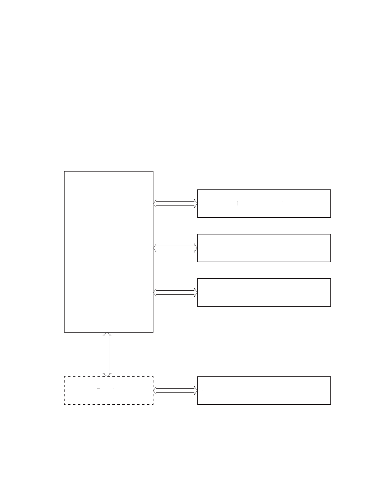
Basic operation
Engine-control system
Formatter
Laser scanner system
Image-formation system
Pickup, feed, and delivery system
Scanning and image capture system (M227/M230)
Engine-control system
Formatter
Laser scanner system
Image-formation system
Pickup, feed, and delivery system
S
canning and image capture system (M227/M230
)
The printer routes all high-level processes through the formatter, which stores font information, processes the
print image, and communicates with the host computer.
The basic printer operation comprises the following systems:
●
Engine-control system
●
Laser scanner system
●
Image-formation system
●
Pickup, feed, and delivery system
●
Scanning and image capture system (M227)
Figure 1-1 Relationship between the main printer systems
ENWW Basic operation 3
Page 26

Sequence of operation
The DC controller PCA controls the operating sequence, as described in the following table.
Table 1-1 Sequence of operation
Period Duration Description
Waiting From the time the power is turned on, the door is
closed, or when the printer exits sleep mode until the
printer is ready for printing.
Standby From the end of the waiting sequence or the last
rotation until the formatter receives a print command,
or until the printer is turned off.
Initial rotation From the time the formatter receives a print command
until the paper enters the paper path.
●
Heats the fuser film in the fuser
●
Detects the presence of the toner cartridge
●
Rotates and stops the main motor
●
Rotates and stops the main fan
●
Cleans the transfer roller
●
Separates the developer roller
●
Remains in the Ready state
●
Enters Active OFF mode if a power control mode
designation command is sent
●
Rotates and stops the main fan
●
Rotates the main motor
●
Rotates the main fan
●
Activates the high-voltage power supply (highvoltage bias)
●
Prepares the laser scanner unit
●
Warms the fuser to the correct temperature
●
Engages the developer roller
Printing From the time the first sheet of paper enters the paper
path until the last sheet passes through the fuser.
Last rotation From the time the last sheet of paper exits the fuser
until the motors stop rotating.
●
Forms the image on the photosensitive drum
●
Transfers the toner to the paper
●
Fuses the toner image onto the paper
●
Stops the main motor
●
Stops the main fan
●
Stops the high-voltage power supply (highvoltage bias)
●
Stops the laser scanner unit
●
Turns the fuser heater off
●
Separates the developer roller
●
If another print command is received, the printer
enters the initial rotation period when the last
rotation is complete.
4 Chapter 1 Theory of operation ENWW
Page 27

Formatter-control system
The formatter performs the following functions:
●
Controls the sleep delay function
●
Receives and processes print data from the various printer inputs
●
Monitors control-panel functions and relays printer status information (through the control panel and the
bidirectional input/output)
●
Develops and coordinates data placement and timing with the DC controller
●
Communicates with the host computer through the network or the bidirectional interface
The formatter receives a print job from the network or bidirectional interface and separates it into image
information and instructions that control the printing process. The DC controller synchronizes the image
formation system with the paper input and output systems, and then signals the formatter to send the print
image data.
Sleep delay
When the printer is in sleep delay mode, the control-panel backlight is turned off, but the printer retains all
printer settings, downloaded fonts, and macros. The default setting is a 1-minute idle time. The setting can be
changed or turned off from the control panel menus.
The printer exits sleep delay mode and enters the warm-up cycle when any of the following occurs.
●
A print job, valid data, or a PML or PJL command is received at the serial port.
●
The control panel is touched (button press or touchscreen touch depending on model).
●
A document is loaded in the document feeder or the scanner lid is opened (M227).
●
A tray is opened.
TIP: Error messages override the sleep delay message. The printer enters sleep mode at the appropriate time,
but the error message continues to appear.
Printer job language (PJL)
PJL is an integral part of printer configuration, in addition to the printer control language (PCL) and PostScript
(PS). With standard cabling, the printer can use PJL to perform a variety of functions.
●
Dynamic I/O switching: The printer can be configured with a host on each I/O by using dynamic I/O
switching. Even when the printer is offline, it can receive data from more than one I/O simultaneously, until
the I/O buffer is full.
●
Context-sensitive switching: The printer can automatically recognize the personality (PS or PCL) of each job
and configure itself to serve that personality.
●
Isolation of print environment settings from one print job to the next: For example, if a print job is sent to
the printer in landscape mode, the subsequent print jobs print in landscape only if they are formatted for
landscape printing.
ENWW Formatter-control system 5
Page 28

Printer management language (PML)
PML allows remote configuration of the printer and status monitoring through the input/output (I/O) ports.
Control panel
The formatter sends and receives printer status and command data to and from the control panel.
Wireless
NOTE: Wireless models only.
Wireless products contain a wireless card to enable 802.11b/g/n wireless communication.
Low end data model (LEDM) overview
The low-end data model (LEDM) provides one consistent data representation method and defines the dynamic
and capabilities tickets shared between clients and devices, as well as the access protocol, event, security, and
discovery methods.
Advanced control language (ACL) overview
The advanced control language (ACL) is a language that supports printer control and firmware downloads in
printers that support both PJL/PCL and host-based printing. Each sequence of ACL commands must be
preceded by a unified exit command (UEL) and an @PJL ENTER LANGUAGE=ACL command. The ACL sequence is
always followed by a UEL. Any number of commands can be placed between the UELs. The only exception to
these rules is the download command. If a firmware download is done, the download command must be the
last command in the sequence. It will not be followed by a UEL.
The firmware searches for the UEL sequence when parsing commands. However, while downloading binary data
such as host-based code or NVRAM data, the firmware suspends UEL parsing. To handle hosts that “disappear”
during binary sequences, the firmware times out all ACL command sessions. If a timeout occurs during a nondownload command sequence, it is treated as the receipt of a UEL. If a timeout occurs during firmware
download, the printer resets.
CPU
The formatter incorporates an 800 MHz processor.
Input/output (I/O)
The following sections discuss the input and output features of the printer.
USB
The printer includes a universal serial bus (USB) 2.0 connection.
USB hosts
The printer includes USB hosts for USB flash drive and wireless communication control.
10/100 networking
All printer models except the M203d include a 10/100 network (Ethernet) connection.
6 Chapter 1 Theory of operation ENWW
Page 29

Fax
NOTE: M227fdn/fdw and M230fdw models only.
The printer includes a fax phone line connection.
Memory
If the printer encounters a problem when managing available memory, a clearable warning message displays on
the control panel.
Firmware
The formatter stores the printer firmware. A remote firmware update process is used to overwrite and update
the firmware.
Nonvolatile random access memory (NVRAM)
The printer uses nonvolatile memory (NVRAM) to store I/O and information about the print environment
configuration. The contents of NVRAM are retained when the printer is turned off or disconnected.
Flash memory
DRR: Stores software applications. When the printer power is turned off, the data stored in DRR is erased.
NAND: Stores fax memory (M227fdn/fdw and M230fdw models only). When the printer power is turned off, the
data stored in NAND is preserved.
Random access memory
DDR memory
●
533 Mhz, 256 MB (M203, M206)
●
800 Mhz, 256 MB (M227, M230)
Flash memory
●
128 MB NAND flash
HP Memory Enhancement technology (MEt)
The HP Memory Enhancement technology (MEt) effectively doubles the standard memory through a variety of
font- and data-compression methods.
NOTE: The MEt is available only in PCL mode; it is not functional when printing in PS mode.
ENWW Formatter-control system 7
Page 30
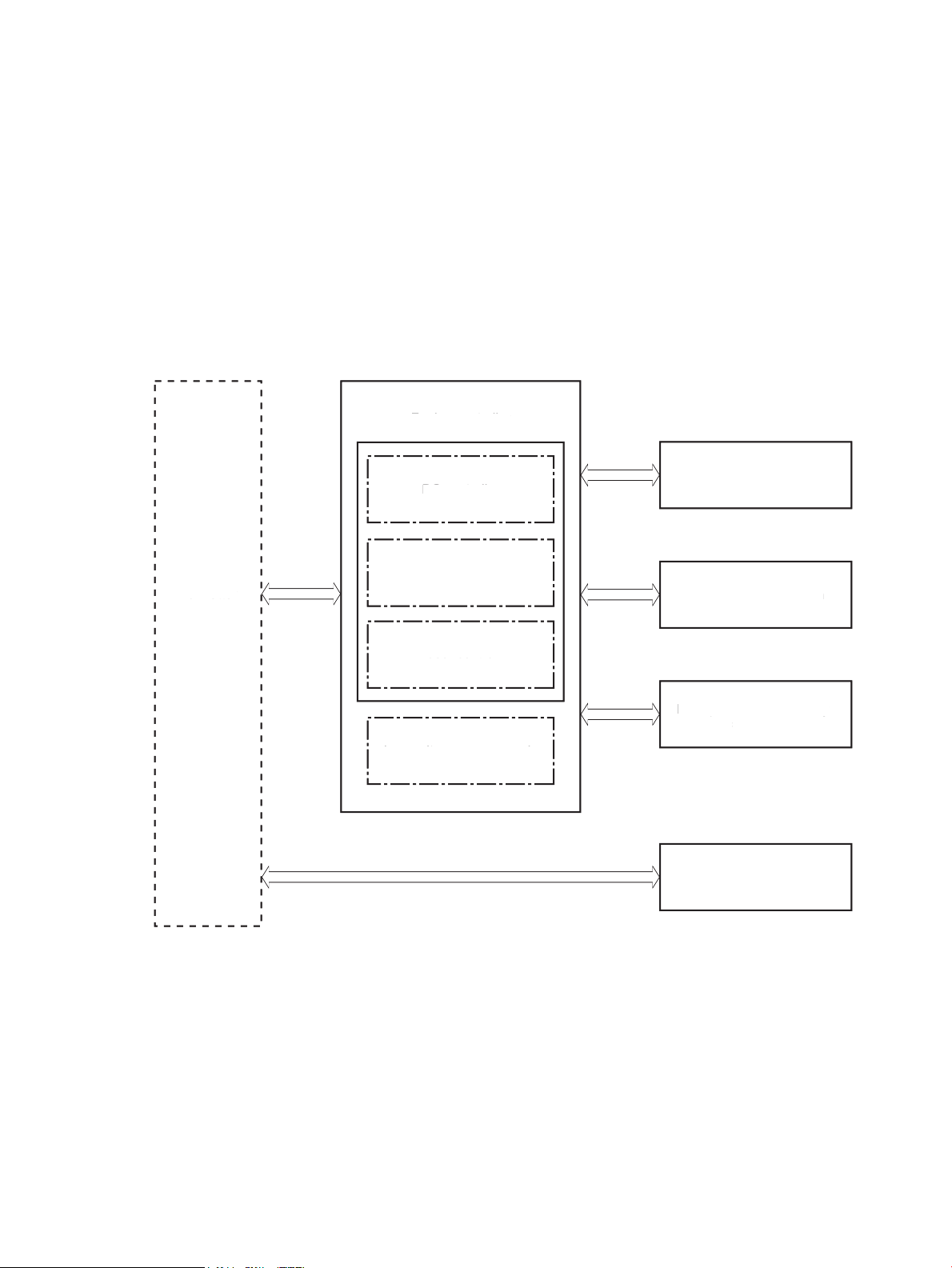
Engine-control system
Formatter
Engine-control system
Engine controller
DC controller
High-voltage power supply
Laser scanner system
Image-formation system
Pickup, feed, and delivery
system
Low-voltage power supply
Fuser control
Scanning and image
capture system (M227)
Formatter
Engine-control system
Engine controller
DC controller
igh-voltage power suppl
y
Laser scanner system
Image-formation system
Pickup, feed, and delivery
stem
Low-voltage power suppl
y
F
user co
ntrol
canning and image
apture system (M227
)
The engine-control system receives commands from the formatter and interacts with the other main systems
to coordinate all printer functions. The engine-control system consists of the following components:
●
DC controller
●
Low-voltage power supply
●
High-voltage power supply
●
Fuser power supply
Figure 1-2 Engine-control system
8 Chapter 1 Theory of operation ENWW
Page 31

DC controller
Transfer front guide
High-voltage
power supply
Fan
Cartridge
LED
Motor
Solenoid
Switch
Photointerrupter
Formatter
Control panel
Laser scanner
assembly
Fuser
AC input
Low-voltage
power supply
DC controller
Sensor
Engine controller
Transfer roller
Image Scanner
(M227)
Transfer front guid
e
igh-volta
ge
ower suppl
y
F
an
artrid
ge
LED
tor
olenoi
d
witc
h
Photointerrupter
Formatter
ontrol panel
L
aser scanne
r
assembl
y
F
use
r
AC inpu
t
Low-volta
ge
ower suppl
y
DC controller
ensor
Engine controller
Transfer roller
Image Scanner
M227
)
The DC controller controls the operation of the printer and its components. The DC controller starts the printer
operation when the printer power is turned on and the power supply sends DC voltage to the DC controller. After
the printer enters the standby period, the DC controller sends out various signals to operate motors, solenoids,
and other printer components based on the print command and image data that the host computer sends.
Figure 1-3 DC controller block diagram
Component type Abbreviation Description
Motor M1 Main motor
Fan FM1 Main fan
M6 Scanner motor
ENWW Engine-control system 9
Page 32

Component type Abbreviation Description
Solenoid SL1 Pickup solenoid
SL2 Developer alienation solenoid
SL3 Duplex switchback solenoid
Switch SW1 Developer alienation switch
SW501 Cartridge door switch
SW740 Power switch
Photointerrupter PS601 Main motor rotation number sensor
SR760 Top of page (TOP) sensor
SR770 Media out sensor
SR771 Pickup media width sensor
SR780 Fuser output sensor
SR781 Fuser media width sensor
Sensor - Environment sensor
LED LED391 Pre-exposure LED
LED740 Power supply LED
10 Chapter 1 Theory of operation ENWW
Page 33

Motor control
The engine control system has two motors.
The DC controller monitors the motors to determine if they have failed. It notifies the formatter when it
encounters the following conditions:
●
●
Table 1-2 Motors
Abbreviation Name Purpose Failure detection
Startup failure: the motors do not reach a specified speed within a specified time from when the motors
start.
Rotational failure: the rotational speed of the motors is not in the specified range for a specified time after
the motors reach a specified speed.
Fan control
The printer has one fan. The fan prevents the temperature from rising in the printer.
Table
M1 Main motor Pickup roller, photosensitive drum, feed roller,
pressure roller, output roller, duplex registration
roller
M6 Scanner motor Drives the scanner mirror Yes
1-3 Fans
Abbreviation Name Cooling area Type Speed Failure
FM1 Main fan Inside the printer Intake Full Yes
Yes
detection
ENWW Engine-control system 11
Page 34

Low-voltage power supply
The low-voltage power-supply (LVPS) circuit converts the AC power from the wall receptacle into the DC voltage
used by the printer components.
The following two printer states relate to the low-voltage power supply:
●
Inactive OFF: In this state, the printer power is turned off.
●
Active OFF: In this state, the printer is in sleep mode. The low-voltage power supply only sends power to
the formatter and DC controller.
12 Chapter 1 Theory of operation ENWW
Page 35

AC input
Fuse
FU101
Rectifying
circuit
Frequency
detection circuit
(220-240V only)
+24V
generation
circuit
Protection
circuit
+3.3V
generation
circuit
Formatter
+3.3F
FET
/3.3FON
FET
LVM
FREQSNS
Low-voltage power supply
Fuser
High-voltage power supply
SW740
+3.3V
+5V
generation
circuit
DC controller
+3.3U
FET
+24U
SW501
Motor circuit
FET
+24P
+5R
+3.3V
+24V
+24F
24FON
+24F
+24V
Figure 1-4 Low-voltage power-supply circuit
Table 1-4 List of DC voltages
DC power supply Description
+24V +24V Constantly supplied
+24U Stopped when cartridge door is opened. (SW501)
Stopped during active OFF or inactive OFF
ENWW Engine-control system 13
Page 36

Table 1-4 List of DC voltages (continued)
DC power supply Description
+3.3V +3.3V Constantly supplied
+5V +5R Constantly supplied
Overcurrent/overvoltage protection
The overcurrent/overvoltage protection function automatically stops supplying DC voltage to the printer
components whenever it detects excessive current or abnormal voltage. The low-voltage power supply has a
protective function against overcurrent and overvoltage to prevent failures in the power supply circuit. In
addition, two fuses in the low-voltage power supply protect against an overcurrent event. If an overcurrent
event occurs in the AC line, the fuse blows and stops the flow of AC power.
+24P Stopped when cartridge door is opened. (SW501)
Stopped during active OFF or inactive OFF
+24F Constantly supplied
Stopped during active OFF or inactive OFF
+3.3U Supplied only during printing and stopped during standby
Stopped during active OFF or inactive OFF
+3.3F Constantly supplied
Stopped during inactive OFF
Stopped during active OFF or inactive OFF
CAUTION: If the low-voltage power supply is not supplying DC voltage, the protective circuit might be running.
In this case, turn the printer off, and then disconnect the power cable. Do not connect the power cable or turn
the printer on again until the root cause is found and corrected.
WARNING! For personal safety, the printer interrupts +24U and +24P power when the cartridge door detection
switch is turned off. This stops DC power supply to the motor and solenoids. The remote switch control circuit
turns the printer power on or off so that AC power flows even when the power switch is turned off. Disconnect
the printer power cable before disassembling the printer.
Low-voltage power supply failure detection
The only time the DC controller detects a failure of the low-voltage power supply is when the printer power
cable is connected to a power source. If the low-voltage power supply outputs 24F when the 24FON signal is
ON, the DC controller reports a low-voltage power supply failure.
High-voltage power supply
The DC controller controls the high-voltage power supply (HVPS) to generate biases. The HVPS delivers highvoltage biases to the following components used to transfer toner during the image-formation process:
●
Primary charging roller (in the toner cartridge)
●
Developing roller (in the toner cartridge)
●
Developer blade (in the toner cartridge)
14 Chapter 1 Theory of operation ENWW
Page 37

●
PR
DV
TR
Primary
charging bias
circuit
Developing
bias circuit
Transfer bias
circuit
To primary charge roller
To developing blade
Photosensitive drum
Transfer roller
Cartridge
Engine controller
DC controller High-voltage power supply
To developing roller
Developing
blade bias
circuit
TE
Transfer front guide
PG
Transfer front
guide bias
circuit
Transfer front guide
●
Transfer roller
High-voltage power supply circuits
The high-voltage power supply contains the following separate circuits.
Figure 1-5 High-voltage power supply circuits
Fuser control
The printer uses an on-demand fusing method. The fuser heater control circuit and the fuser heater safety
circuit control the fuser temperature according to commands from the DC controller. The fuser consists of the
following major components:
ENWW Engine-control system 15
Page 38

Figure 1-6 Fuser components
FUSER TEMPERATURE signal
FUSER HEATER CONTROL signal
Low-voltage power supply
TH1
TP1
H1
Pressure roller
Fuser film
Fuser heater
safety circuit
Fuser heater
control circuit
DC controller
Engine controller
Table 1-5 Fuser components
Component Name Abbreviation Function
Fuser heater H1 Heats the fuser film assembly
Thermistor (contact type) TH1 Detects the temperature of the fuser heater
Thermoswitch (contact type) TP1 Prevents an abnormal temperature rise in the fuser
heater
16 Chapter 1 Theory of operation ENWW
Page 39

Fuser control functions
CPU
Fuser heater
safety circuit
FREQSNS
FSRD
RLYD
FSRTHSNS
RL101
Fuser heater (H1)
Fuser film assembly
Pressure roller
DC controller
Engine controller
Low-voltage power supply
Fuser heater
control circuit
Relay control
circuit
Frequency detection
circuit (220-240V
model only)
Fuser
TH1
TP1
TP1: Thermoswitch
TH1: Thermistor
Figure 1-7 Fuser control
The printer has the following fuser control functions.
1-6 Fuser control functions
Table
Failure detection function Supported feature
Fuser temperature control Yes
Heat-up error detection Yes
ENWW Engine-control system 17
Page 40

Table 1-6 Fuser control functions (continued)
Failure detection function Supported feature
Low temperature error detection Yes
High temperature error detection Yes
Breaking of a heater wire detection No
Driving-circuit failure detection (frequency detection circuit failure detection) Yes
Low-voltage power supply failure detection No
Fuser pressure-release mechanism failure detection No
Fuser type discrepancy detection No
Fuser type identification detection No
Fuser presence detection No
Fuser life detection No
Fuser roller cleaning Yes
Fuser heater protection
Fuser heater protection is a feature that detects excessive temperatures in the fuser and interrupts the power
supply to the fuser heater.
The following three protective components prevent the fuser heater from excessive rising temperature:
●
DC controller: The DC controller constantly monitors the temperature of the thermistor. When the DC
controller detects an excessive temperature, it deactivates the FUSER HEATER CONTROL signal and turns
off the relays (RL101) to interrupt power supply to the fuser heater.
●
Fuser heater safety circuit: The fuser heater safety circuit constantly monitors the detected temperature of
the thermistors. When the fuser heater safety circuit detects an excessive temperature, it turns off the
relays (RL101) to interrupt power supply to the fuser heater.
●
Thermoswitch: When the thermal fuse detects an abnormally high temperature in the fuser heater, the
contact of the thermoswitch opens and interrupts the power supply to the fuser heater.
18 Chapter 1 Theory of operation ENWW
Page 41

Engine laser scanner system
Laser assembly
BD sensor
Scanner mirror
Scanner motor assembly
Photosensitive drum
DC controller
The DC controller receives instructions from the formatter in order to control the laser scanner system.
The DC controller signals the lasers to emit light, and the laser beams pass through lenses and onto the scanner
mirror, which rotates at a constant speed. The mirror reflects the beam onto the photosensitive drum inside of
the toner cartridge in the pattern required for the image, exposing the surface of the drum so that it can receive
toner.
The main components of the laser scanner system, which are controlled by the VIDEO signals sent from the DC
controller, are:
●
Laser assembly
●
Scanner motor assembly
●
Beam detect (BD) sensor
●
Scanner mirror
Figure 1-8 Laser scanner system
ENWW Engine laser scanner system 19
Page 42

Laser scanner failure detection
The DC controller detects the following laser scanner failures:
Failure detection function Supported feature
Safety
Beam detect (BD) failure detection: A specified BD interval is not detected within a specified
period of time during the scanner motor rotation.
Laser scanner motor startup failure: The scanner motor does not reach a specified rotation
frequency within a specified period of time from when the laser scanner starts up.
Laser scanner motor rotational failure: The laser scanner motor does not reach a specified
rotational frequency within a specified period of time during a print operation.
Laser scanner failure detection: A specified laser intensity is not detected. No
Yes
Yes
Yes
The laser scanner assembly has a mechanical laser shutter. For the safety of users and service technicians, the
laser shutter interrupts the optical path of the laser scanner assembly when the cartridge door is opened.
20 Chapter 1 Theory of operation ENWW
Page 43

Image-formation process
Engine controller
DC controller
High-voltage power supply
Cartridge
Fuser
Laser scanner ass’y
Transfer roller
The DC Controller controls the internal components of the image formation system (according to commands
received from the formatter) to form the toner image on the photosensitive drum surface. The toner image is
then transferred to the print media and fused.
The image-formation system consists of the following components:
●
Toner cartridge
●
Transfer roller
●
Fuser
●
Laser scanner
●
High-voltage power supply
Figure 1-9 Image-formation system
The main motor (M1) drives the following image formation components:
●
●
●
●
●
●
Photosensitive drum
Developing roller
Primary charging roller (follows the photosensitive drum)
Transfer roller (follows the photosensitive drum)
Pressure roller
Fuser film (follows the pressure roller)
NOTE: The primary charging roller and developer roller are located in the toner cartridge.
ENWW Engine laser scanner system 21
Page 44

Figure 1-10 Main motor (M1) and image formation components
DC controller
Engine controller
M1
Engine controller
LED391
SW1
Environment sensor
DC controller
Abbreviation Component
M1 Main motor
The following figure shows the sensors in the image-formation system.
Figure 1-11 Sensors
Table
1-7 Sensors
Abbreviation Component
LED391 Pre-exposure LED
- Environment sensor
SW1 Developer alienation switch
22 Chapter 1 Theory of operation ENWW
Page 45

The image-formation process consists of ten steps divided into five functional blocks.
7. Fusing
6. Separation
5. Transfer
Latent image formation
3. Laser beam exposure
Developing
4. Developing
Drum cleaning
8. Drum cleaning
1. Pre-exposure
2. Primary charging
Pickup
TransferFusing
Delivery
: Paper path
: Direction of drum rotation
: Functional block
: Step
Figure 1-12 Image-formation process
Table 1-8 Image formation process
Functional block Steps Description
Latent image formation 1. Pre-exposure
Development 4. Development Toner adheres to the electrostatic latent image on the
Transfer 5. Transfer
Fusing 7. Fusing The toner fuses to the paper to make a permanent
Drum cleaning 8. Drum cleaning Residual toner is removed from the drum.
An invisible latent image forms on the surface of the
photosensitive drums.
2. Primary charging
3. Laser-beam exposure
photosensitive drum.
The toner image transfers to the paper.
6. Separation
image.
ENWW Engine laser scanner system 23
Page 46

Step 1: Pre-exposure
Pre-exposure LED
Photosensitive drum
Photosensitive drum
Primary charging roller
Primary charging bias
To prepare for primary charging, light from the pre-exposure LED strikes the surface of the photosensitive drum
to remove any residual electrical charges from the drum surface.
Figure 1-13 Pre-exposure
Step 2: Primary charging
To prepare for latent image formation, the surface of the photosensitive drum is charged with a uniform
negative charge. The primary charging roller receives the primary charging bias, and then the roller charges the
drum directly.
Figure 1-14 Primary charging
24 Chapter 1 Theory of operation ENWW
Page 47

Step 3: Laser-beam exposure
Photosensitive drum
Laser beam
Developer roller
Developing bias
Photosensitive drum
Developer blade
The laser beam strikes the photosensitive drum to neutralize the negative charge on portions of the drum
surface. An electrostatic latent image forms where the negative charge was neutralized.
Figure 1-15 Laser-beam exposure
Step 4: Development
Toner acquires a negative charge as a result of the friction from the developing roller rotating against the
developing blade. Developing bias is applied to the developing roller. When the negatively charged toner comes
in contact with the drum, it adheres to the electrostatic latent image. When the toner is on the drum, the image
becomes visible.
Figure 1-16 Development
ENWW Engine laser scanner system 25
Page 48

Step 5: Transfer
Photosensitive
drum
Transfer roller
Paper
Transfer bias
Transfer bias is applied to the transfer roller to give the paper a positive charge. The positively charged paper
attracts the negatively charged toner from the photosensitive drum surface and the image transfers to the
paper.
Figure 1-17 Primary transfer
26 Chapter 1 Theory of operation ENWW
Page 49

Step 6: Separation
Paper
Photosensitive
drum
Transfer roller
Static charge eliminator
Fuser heater
Paper
Pressure roller
Fuser film
The elasticity of the paper and the curvature of the photosensitive drum cause the paper to separate from the
drum surface. The static charge eliminator reduces the electrical charge on the back side of the paper for stable
paper feeding and image quality.
Figure 1-18 Separation
Step 7: Fusing
The toner image is fused onto the paper by heat and pressure.
Figure 1-19 Fusing
ENWW Engine laser scanner system 27
Page 50

Step 8: Drum cleaning
Photosensitive
drum
Transfer roller
Pre-exposure
LED
Primary charging roller
Primary charging bias
Developer roller
Developer
Transfer bias
A reverse charge is applied to the transfer roller and the primary charging roller to transfer any residual toner on
each roller back to the photosensitive drum. This toner is then removed from the drum surface by the
developing roller and deposited in the developer.
Figure 1-20 Drum cleaning
Toner cartridges
Design
The printers support separate toner cartridges and imaging drum cartridges.
The toner cartridge system consists of the following components:
●
Photosensitive drum
●
Developer roller
●
Primary-charging roller
●
Memory chip
28 Chapter 1 Theory of operation ENWW
Page 51

Figure 1-21 Cartridge block diagram
DC controller
Developer roller
Primary charging roller
O cartridge DT cartridge
M1
Memory chip
Photosensitive drum
Table 1-9 Toner cartridge functions
Function Supported feature
Cartridge presence detection Yes
Cartridge life detection Yes
Cartridge mis-installation detection No
Drum discharge No
Developer alienation control Yes
Transfer roller cleaning Yes
Primary charging roller cleaning Yes
ENWW Engine laser scanner system 29
Page 52

Engine pickup, feed, and delivery system
Pickup-and-feed block
Fuser-and-delivery block
Duplex paper path
Simplex paper path
Duplex block
The pickup, feed, and delivery system uses a series of rollers to move the paper through the printer and consists
of the following three functional blocks. The DC controller controls each block to pick up, feed and deliver the
paper (according to commands received from the formatter).
●
Pickup-and-feed block: Controls the movement of the paper from each pickup source to the fuser inlet
●
Fuser-and-delivery block: Controls the movement of the paper from the fuser to the delivery destination
●
Duplex block: Controls the movement of the paper from the delivery destination to the Top of page (TOP)
sensor
Figure 1-22 Pickup, feed, and delivery system
Table 1-10 Pickup, feed, and delivery system functions
Function Supported feature
Tray media size detection No
Tray presence detection No
Tray media surface detection No
Tray media presence detection No
Tray media level detection No
Tray lift-up control No
Tray lift-down control No
Tray multiple-feed prevention mechanism No
Multipurpose tray media presence detection Yes
30 Chapter 1 Theory of operation ENWW
Page 53

Table 1-10 Pickup, feed, and delivery system functions (continued)
Function Supported feature
Multipurpose tray media width detection Yes
Multipurpose tray last-media detection No
Skew-feed prevention mechanism No
Feed speed control Yes
Loop control No
Media detection No
OHT detection No
Image leading edge positioning Yes
Media length detection Yes
Media width detection Yes
Pressure roller pressure release control No
Output bin media-full detection No
Automatic delivery Yes
Duplex switchback control No
Duplex feed control Yes
ENWW Engine pickup, feed, and delivery system 31
Page 54

Sensors and switches
SR770
SR771
SR780
SR781
SR760
The following figure shows the sensors and switches for the pickup, feed, and delivery system.
Figure 1-23 Sensors and switches for the pickup, feed, and delivery system
Table 1-11 Photo sensors and switches
Abbreviation Component
SR760 Top of page (TOP) sensor
SR770 Media out sensor
SR771 Pickup media width sensor
SR780 Fuser output sensor
SR781 Fuser media width sensor
32 Chapter 1 Theory of operation ENWW
Page 55

Motors and solenoids
SL3
M1
SL1
The following figure shows the motors and solenoids for the pickup, feed, and delivery system.
Figure 1-24 Motors and solenoids
Table 1-12 Motors and solenoids
Abbreviation Component
M1 Main motor
SL1 Pickup solenoid
SL3 Duplex switchback solenoid
Jam detection/prevention
The printer uses the following sensors to detect the presence of the paper as it moves through the paper path
and to report to the DC controller if the paper has jammed.
●
Top of page (TOP) sensor (SR760)
●
Fuser output sensor (SR780)
●
Fuser media width sensor (SR781)
ENWW Engine pickup, feed, and delivery system 33
Page 56

Figure 1-25 Jam detection sensors
SR780
SR781
SR760
Duplex paper path
Simplex paper path
The printer determines that a jam has occurred if one of these sensors detects paper at an inappropriate time.
The DC controller stops the print operation and notifies the formatter.
Table
Jam Supported feature
No pick jam 1 Yes
No pick jam 2 No
No pick jam 3 No
No pick jam 4 No
Pickup stay jam 1 Yes
Pickup stay jam 2 No
Pickup stay jam 3 No
Pickup stay jam 4 No
Fuser delivery delay jam 1 Yes
Fuser delivery delay jam 2 No
Fuser delivery delay jam 3 No
Fuser delivery delay jam 4 No
Fuser delivery stay jam 1 Yes
Fuser delivery stay jam 2 No
1-13 Jams that the printer detects
Fuser delivery stay jam 3 No
Fuser delivery stay jam 4 No
34 Chapter 1 Theory of operation ENWW
Page 57

Table 1-13 Jams that the printer detects (continued)
Jam Supported feature
Residual paper jam 1 Yes
Residual paper jam 2 No
Residual paper jam 3 No
Residual paper jam 4 No
Door open jam 1 Yes
Door open jam 2 No
Door open jam 3 No
Door open jam 4 No
Fuser wrap jam 1 Yes
Fuser wrap jam 2 No
Fuser wrap jam 3 No
Fuser wrap jam 4 No
Duplex switchback jam 1 Yes
Duplex switchback jam 2 No
Duplex switchback jam 3 No
Duplex switchback jam 4 No
Duplex re-pickup jam 1 Yes
Duplex re-pickup jam 2 No
Duplex re-pickup jam 3 No
Duplex re-pickup jam 4 No
Delivery delay jam 1 No
Delivery delay jam 2 No
Delivery delay jam 3 No
Delivery delay jam 4 No
Delivery stay jam 1 No
Delivery stay jam 2 No
Delivery stay jam 3 No
Delivery stay jam 4 No
Multiple feed jam 1 No
Multiple feed jam 2 No
Multiple feed jam 3 No
Multiple feed jam 4 No
ENWW Engine pickup, feed, and delivery system 35
Page 58

Scanning and image capture system (MFP printers)
Contact image sensor
Scanner glass
Image scanner
NOTE: This section is for the (MFP printers) only.
The image scanner is located on the top of the printer. The contact image sensor component of the image
scanner captures an electronic image of the document on the glass. The formatter controls the operation of the
image capture system. The image scanner is available in two configurations:
●
Image scanner model: This model consists of only the flatbed image scanner. The document to be scanned
is placed face-down on the scanner glass.
●
Integrated scanner assembly model: This model consists of a document feeder and image scanner. The
document feeder feeds a document to be scanned from the document feeder input tray to the scanner
glass.
Figure 1-26 Image scanner model block diagram
36 Chapter 1 Theory of operation ENWW
Page 59

Figure 1-27 Integrated scanner assembly model block diagram
Contact image sensor
Document Feeder
Image scanner
ENWW Scanning and image capture system (MFP printers) 37
Page 60

Motor and sensors
ADF
Image scanner
Photointerrupter
Sensor
Motor
Formatter
The following figure shows the motors and sensors in the scanning and image capture system.
Figure 1-28 Motor and sensors
Table 1-14 Motor and sensors
Component type Abbreviation Component name
Motor M2 Scan motor (drives document feeder rollers
and contact image sensor)
Sensor CIS Contact image sensor
Photointerrupter PS791 Document feeder document out sensor
PF792 Document feeder TOF sensor
38 Chapter 1 Theory of operation ENWW
Page 61

Document feeder system (MFP printers)
NOTE: This section is for the MFP printers only.
Document feeder simplex operation
The document feeder will not function when the document feeder cover is open. The paper path is incomplete if
the document feeder cover is lifted from the glass.
The standard operation of the document feeder consists of the standby (paper loading) mode, pick, feed, and lift
steps:
●
Standby (paper-loading) mode
In standby mode, the lift plate is in the down position. When a document is loaded into the input tray, the
paper-present sensor detects its presence.
When a copy/scan is initiated, the document feeder motor engages the gear train and raises the lift plate
until the document makes contact with the pick roller. The document feeder then begins the pick, feed,
and lower sequence.
●
Pick
The pick roller rotates and moves one or more sheets forward into the document feeder where the sheets
engage with the separation roller. The separation roller contacts the document feeder separation pad,
which separates multiple sheets into a single sheet.
●
Feed
The single sheet continues through the document feeder paper path (aided by the pre-scan rollers) until
the leading edge of the page activates the top-of-form sensor. Activation of this sensor initiates the scan
process, and the scanner acquires the image as the document moves over the document feeder glass. The
post-scan rollers then eject the sheet into the output area. The pick and feed steps are repeated as long as
paper is detected by the paper-present sensor.
●
Home
When the form sensor detects the trailing edge of the last page, the last sheet is ejected and the motor
turns on a sequence that rests the separation floor back down in standby mode, which allows it to detect
when more media is loaded.
ENWW Document feeder system (MFP printers) 39
Page 62

Fax functions and operation (fax models only)
The following sections describe the printer fax capabilities.
Computer and network security features
The printer can send and receive fax data over telephone lines that conform to public switch telephone network
(PSTN) standards. The secure fax protocols make it impossible for computer viruses to be transferred from the
telephone line to a computer or network.
The following printer features prevent virus transmission:
●
No direct connection exists between the fax line and any devices that are connected to the USB or Ethernet
ports.
●
The internal firmware cannot be modified through the fax connection.
●
All fax communications go through the fax subsystem, which does not use Internet data-exchange
protocols.
PSTN operation
The PSTN operates through a central office (CO) that generates a constant voltage on the TIP and RING wires
(48 V, usually). A device goes on-hook by connecting impedance (such as 600 ohms for the U.S.) across the TIP
and RING so that a line current can flow. The CO can detect this current and can send impulses like dial tones.
The printer generates more signaling tones, such as dialing digits, to tell the CO how to connect the call. The
printer can also detect tones, such as a busy tone from the CO, that tell it how to behave.
When the call is finally connected, the CO behaves like a piece of wire connecting the sender and receiver. This is
the period during which all of the fax signaling and data transfer occurs. When a call is completed, the circuit
opens again and the line-current flow ceases, removing the CO connection from both the sender and the
receiver.
On most phone systems, the TIP and RING signals appear on pins 3 and 4 of the RJ-11 modular jack (the one on
the fax card, as defined in the common 6 wire RJ standard). These two signals do not have to be polarized
because all of the equipment works with either TIP or RING on one pin and the other signal on the other pin. This
means that cables of either polarity can interconnect and still work.
These basic functions of PSTN operation are assumed in the design of the fax subsystem. The printer generates
and detects the signaling tones, currents, and data signals that are required to transmit and receive faxes using
the PSTN.
Receive faxes when you hear fax tones
In general, incoming faxes to the printer are automatically received. However, if other devices are connected to
the same phone line, the printer might not be set to answer automatically.
If the printer is connected to a phone line that receives both fax and phone calls, and you hear fax tones when
you answer the extension phone, receive the fax in one of two ways:
●
If you are near the printer, press Start Fax on the control panel.
●
Press 1-2-3 in sequence on the extension phone keypad, listen for fax transmission sounds, and then
hang up.
40 Chapter 1 Theory of operation ENWW
Page 63

NOTE: In order for the 1-2-3 sequence to work, the extension phone setting must be set to On in the Fax
Setup menu.
Distinctive ring function
Distinctive ring is a service that a telephone company provides. The distinctive ring service allows three phone
numbers to be assigned to one phone line. Each phone number has a distinctive ring. The first phone number
has a single ring, the second phone number has a double ring, and the third phone number has a triple ring.
NOTE: The printer has not been tested with all of the distinctive-ring services that telephone companies
provide in all countries/regions. HP does not guarantee that the distinctive-ring function will operate correctly in
all countries/regions. Contact the local phone service provider for assistance.
Set up the distinctive ring function
1. Open the Setup menu.
2. Open the Fax menu.
3. Select the Basic Setup menu.
4. Select the Distinctive Ring setting.
5. Use the arrow buttons to select one of the following options:
●
All Rings (default setting)
●
Single
●
Double
●
Triple
●
Double and Triple
Fax by using voice over IP (VOIP) services
Voice over IP (VoIP) services provide normal telephone service, including long distance service through a
broadband Internet connection. These services use packets to break up the voice signal on a telephone line and
transmit it digitally to the receiver, where the packets are reassembled. The VoIP services are often not
compatible with fax machines. The VoIP provider must state that the service supports fax over IP services.
Because the installation process varies, the VoIP service provider will have to assist in installing the printer fax
component.
Although a fax might work on a VoIP network, it can fail when the following events occur:
●
Internet traffic becomes heavy and packets are lost.
●
Latency (the time it takes for a packet to travel from its point of origin to its point of destination) becomes
excessive.
If you experience problems using the fax feature on a VoIP network, make sure that all of the printer cables and
settings are correct. Configuring the Fax Speed setting to Medium(V.17) or Slow(V.29) can also improve your
ability to send a fax over a VoIP network.
If you continue to have problems faxing, contact your VoIP provider.
ENWW Fax functions and operation (fax models only) 41
Page 64

The fax subsystem
The formatter, fax card, firmware, and software all contribute to the fax functionality. The designs of the
formatter and fax card, along with parameters in the firmware, determine the majority of the regulatory
requirements for telephony on the printer.
The fax subsystem is designed to support V.34 fax transmission, low speeds (such as V.17 fax), and older fax
machines.
Fax card in the fax subsystem
Two versions of the fax card are used in the printer. One is used in the North American, South American, and
Asian countries/regions. The other is used primarily in European countries/regions.
The fax card contains the modem chipset (DSP and CODEC) that controls the basic fax functions of tone
generation and detection, along with channel control for fax transmissions. The CODEC and its associated
circuitry act as the third-generation silicon data access arrangement (DAA) to comply with worldwide regulatory
requirements.
The only difference between the two versions is that each version is compliant with the 2/4-wire phone jack
system from the respective country/region.
Safety isolation
The most important function of the fax card is the safety isolation between the high-voltage, transient-prone
environment of the telephone network (TNV [telephone network voltage]) and the low-voltage analog and
digital circuitry of the formatter (SELV [secondary extra-low voltage]). This safety isolation provides both
customer safety and printer reliability in the telecom environment.
Any signals that cross the isolation barrier do so magnetically. The breakdown voltage rating of barrier-critical
components is greater than 5 kV.
Safety-protection circuitry
In addition to the safety barrier, the fax card protects against over-voltage and over-current events.
Telephone over-voltage events can be either differential mode or common mode. The event can be transient in
nature (a lightning-induced surge or ESD) or continuous (a power line crossed with a phone line). The fax card
protection circuitry provides margin against combinations of over-voltage and overcurrent events.
Common mode protection is provided by the selection of high-voltage-barrier critical components (transformer
and relay). The safety barrier of the fax card PCB traces and the clearance between the fax card and surrounding
components also contribute to common mode protection.
A voltage suppressor (a crowbar-type thyristor) provides differential protection. This device becomes low
impedance at approximately 300 V differential, and crowbars to a low voltage. A series thermal switch works in
conjunction with the crowbar for continuous telephone line events, such as crossed power lines.
All communications cross the isolation barrier magnetically. The breakdown voltage rating of barrier-critical
components is greater than 5 kV.
Data path
TIP and RING are the two-wire paths for all signals from the telephone network. All signaling and data
information comes across them, including fax tones and fax data.
42 Chapter 1 Theory of operation ENWW
Page 65

Hook state
The telephone network uses DC current to determine the hook state of the telephone, so line current must be
present during a call. The silicon DAA provides a DC holding circuit to keep the line current constant during a fax
call.
The silicon DAA converts the analog signal to a digital signal for DSP processing, and also converts the digital
signal to an analog signal for transmitting data through a telephone line.
The magnetically coupled signals that cross the isolation barrier go through either a transformer or a relay.
The DSP in the fax card communicates with the ASIC in the formatter using the high-speed serial interface.
Another magnetically coupled signal is the control signal that disconnects the downstream telephone devices
(such as a phone or answering machine). A control signal originating on the DSP can change the relay state,
causing the auxiliary jack (downstream jack) to be disconnected from the telephone circuit.
The printer takes control of calls that it recognizes as fax calls. If the printer does not directly pick up the call, it
monitors incoming calls for the fax tone or for the user to direct it to receive a fax. This idle mode is also called
eavesdropping. This mode is active when the printer is on-hook but current exists in the downstream phone line
because another device is off-hook. During eavesdropping, the receive circuit is enabled but has a different gain
from the current that is generated during normal fax transmissions.
The printer does not take control of the line unless it detects a fax tone or the user causes it to connect
manually. This feature allows the user to make voice calls from a phone that is connected to the printer without
being cut off if a fax is not being received.
Downstream device detection
The line voltage monitoring module of the silicon DAA can detect the line state as well as the downstream
device. It tells DSP via DIB that an active device (telephone, modem, or answering machine) is connected to the
auxiliary port on the printer (the right side of the dual RJ-11 jack). The DSP uses the signal to make sure that the
printer does not go off-hook (and disconnects a downstream call) until it has been authorized to do so (by a
manual fax start or the detection of the appropriate tones).
Hook switch control
In the silicon DAA the CODEC controls the hook switch directly. The CODEC is activated when it receives
commands from the DSP. When the circuit is drawing DC current from the central office it is considered off-hook.
When no DC current flows the state is considered on-hook.
Ring detect
Ring detect is performed by the line voltage monitoring module of the silicon DAA, and is a combination of
voltage levels and cadence (time on and time off). Both must be present to detect a valid ring. The CODEC works
with DSP as well as the firmware to determine if an incoming signal is an answerable ring.
Line current control
The DC current from the CO needs to have a path to flow from TIP to RING. The DC impedance emulation line
modulator and DC terminations modules in the silicon DAA act as a DC holding circuit, and work with the
firmware to achieve the voltage-current characteristic between TIP and RING. The impedance (the currentvoltage characteristic) changes corresponding to certain special events, such as pulse dialing or when the printer
goes on-hook.
ENWW Fax functions and operation (fax models only) 43
Page 66

Billing or metering tone filters
Switzerland and Germany provide high-frequency AC signals on the phone line in order to bill customers.
A filter in a special fax cable (for certain countries/regions), can filter these signals. Because these billing signals
are not used in the U.S., these filters are not present in the U.S. fax cable.
To obtain a special fax cable, contact your local telephone service provider.
Fax page storage in flash memory
Fax pages are the electronic images of the document page. They can be created in any of three ways: scanned
to be sent to another fax machine, generated to be sent by the computer, or received from a fax machine to be
printed.
The printer stores all fax pages in flash memory automatically. After these pages are written into flash memory,
they are stored until the pages are sent to another fax machine, printed on the printer, transmitted to the
computer, or erased by the user.
These pages are stored in flash memory, which is the nonvolatile memory that can be repeatedly read from,
written to, and erased. The printer has 8 MB of flash memory, of which 7.5 MB is available for fax storage. The
remaining 0.5 MB is used for the file system and reclamation. Adding RAM does not affect the fax page storage
because the printer does not use RAM for storing fax pages.
Stored fax pages
The user can reprint stored fax receive pages in case of errors. For a fax send, the printer will resend the fax in
case of errors. The printer will resend stored fax pages after a busy signal, communication error, no answer, or
power failure. Other fax devices store fax pages in either normal RAM or short-term RAM. Normal RAM
immediately loses its data when power is lost, while short-term RAM loses its data about 60 minutes after
power failure. Flash memory maintains its data for years without any applied power.
Advantages of flash memory storage
Fax pages that are stored in flash memory are persistent. They are not lost as a result of a power failure, no
matter how long the power is off. Users can reprint faxes in case the toner cartridge runs out of toner or the
printer experiences other errors while printing faxes.
The printer also has scan-ahead functionality that makes use of flash memory. Scan-ahead automatically scans
pages into flash memory before a fax job is sent. This allows the sender to pick up the original document
immediately after it is scanned, eliminating the need to wait until the fax transmission is complete.
Because fax pages are stored in flash memory rather than RAM, more RAM is available to handle larger and
more complicated copy and print jobs.
44 Chapter 1 Theory of operation ENWW
Page 67

2 Solve problems
●
For additional service and support
●
Troubleshooting process
●
Tools for troubleshooting
●
Improve print quality
●
Print quality troubleshooting guide
●
Improve copy and scan image quality (M227)
●
Clean the printer
●
Solve paper-handling problems
●
Solve performance problems
●
Solve connectivity problems
●
Service mode functions
●
Solve fax problems (fax models only)
●
Solve email problems (M129/M134)
●
Update the firmware
ENWW 45
Page 68

For additional service and support
HP service personnel, go to the Service Access Workbench (SAW) at http://sawpro.glb.itcs.hp.com.
Channel partners, go to HP Channel Services Network (CSN) at www.hp.com/partners/csn .
At these locations, find information on the following topics:
●
Install and configure
●
Printer specifications
●
Up-to-date control panel message (CPMD) troubleshooting
●
Solutions for printer issues and emerging issues
●
Remove and replace part instructions and videos
●
Service advisories
●
Warranty and regulatory information
Channel partners, access training materials in the HP University and Partner Learning Center at
https://content.ext.hp.com/sites/LMS/HPU.page.
To access HP PartSurfer information from any mobile device, go to http://partsurfermobile.hp.com/ or scan the
Quick Response (QR) code below.
46 Chapter 2 Solve problems ENWW
Page 69

Troubleshooting process
Determine the problem source
When the printer malfunctions or encounters an unexpected situation, the printer control panel alerts the user
to the situation. This section contains a pre-troubleshooting checklist and a troubleshooting flow chart to filter
out many possible causes of the problem. Use the pre-troubleshooting checklist to gather information about
the problem from the customer. Use the troubleshooting flowchart to help diagnose the root cause of the
problem. The remainder of this chapter provides steps for correcting problems.
●
Use the pre-troubleshooting check list to gather information about the problem from the customer. See
Pre-troubleshooting checklist on page 47.
●
Use the troubleshooting flowchart to pinpoint the root cause of hardware malfunctions. The flowchart
provides guides to the section of this chapter that contain steps to correct the malfunction. See
Troubleshooting flowchart on page 48.
Before beginning any troubleshooting procedure, check the following issues:
●
Are supply items within their rated life?
●
Does the configuration page reveal any configuration errors?
NOTE: The customer is responsible for checking supplies and for using supplies that are in good condition.
Pre-troubleshooting checklist
The following table includes basic questions to ask the customer to quickly help define the problem(s).
General topic Questions
Environment
Media
Input tray
●
Is the printer installed on a solid, level surface (+/- 1°)?
●
Is the power-supply voltage within ± 10 volts of the specified power source?
●
Is the power-supply plug inserted in the printer and the outlet?
●
Is the operating environment within the specified parameters?
●
Is the printer exposed to ammonia gas, such as that produced by diazo copiers or
office cleaning materials?
NOTE: Diazo copiers produce ammonia gas as part of the copying processes.
Ammonia gas (from cleaning supplies or a diazo copier) can have an adverse effect
on some printer components (for example, the toner cartridge or image drum).
●
Is the printer exposed to direct sunlight?
●
Does the customer use only supported media?
●
Is the media in good condition (no curls, folds, or distortion)?
●
Is the media stored correctly and within environmental limits?
●
Is the amount of media in the tray within specifications?
●
Is the media correctly placed in the tray?
●
Are the paper guides aligned with the stack?
Toner cartridge
●
Are the toner cartridge and imaging drum installed correctly?
ENWW Troubleshooting process 47
Page 70

General topic Questions
Transfer roller and fuser
Covers
Condensation
Miscellaneous
Troubleshooting flowchart
This flowchart highlights the general processes to follow to quickly isolate and solve printer hardware problems.
Each row depicts a major troubleshooting step. Follow a “yes” answer to a question to proceed to the next major
step. A “no” answer indicates that more testing is needed. Go to the appropriate section in this chapter, and
follow the instructions there. After completing the instructions, go to the next major step in this troubleshooting
flowchart.
●
Are the transfer roller and fuser installed correctly?
●
Is the toner cartridge door closed?
●
Does condensation occur following a temperature change (particularly in winter
following cold storage)? If so, wipe affected parts dry or leave the printer on for 10 to
20 minutes.
●
Were a toner cartridge or imaging drum opened soon after being moved from a cold
to a warm room? If so, allow the toner cartridge or imaging drum to sit at room
temperature for 1 to 2 hours.
●
Check for and remove any non-HP components (toner cartridge or imaging drum)
from the printer.
●
Remove the printer from the network (network models) and ensure that the failure is
associated with the printer before beginning troubleshooting.
Table
2-1 Troubleshooting flowchart
1
Power on
2
Control panel
messages/Alerts
3
Event log
4
Information pages
5
Print quality
Is the printer on and does a readable message
display or is the Ready LED illuminated (depends
on printer model)?
Yes
Does the message Ready display on the control
panel or is the Ready LED illuminated?
Yes
Open the Troubleshooting menu (depends on
printer model) and print an event log to see the
history of errors with this printer.
Does the event log print?
Yes
Print the configuration pages to verify all printer
settings.
Yes
Does the print quality meet the customer's
requirements?
Yes
No
No
No
No
No
Follow the power-on troubleshooting checks. See Power-on checks
on page 49.
After the control panel display is functional, see step 2.
After the errors have been corrected, go to step 3.
If the event log does not print, check for error messages.
If paper jams inside the printer, see the jams section of the printer
service manual.
If error messages display on the control panel when trying to print an
event log, see the control panel message section of the printer
troubleshooting service manual.
After successfully printing and evaluating the event log, see step 4.
After evaluating the configuration pages, see step 5.
Compare the images with the sample defects in the image defect tables.
See the images defects table in the printer troubleshooting service
manual.
After the print quality is acceptable, see step 6.
48 Chapter 2 Solve problems ENWW
Page 71

Table 2-1 Troubleshooting flowchart (continued)
6
Interface
Can the customer print successfully from the
host computer?
Yes. This is the end of the
troubleshooting process.
Power subsystem
Turn on the power. If the control panel does not illuminate, perform the power-on checks to find the cause of
the problem.
Power-on checks
1. Verify that the printer is plugged into an active electrical outlet that delivers the correct voltage.
2. Verify that the power switch is in the on position.
3. Make sure that the printer makes the expected start up sounds.
NOTE: If the printer does not power on, the overcurrent/overvoltage protection circuit in the low-voltage
power supply might be functioning. This circuit automatically stops supplying DC voltage to the printer
components whenever it detects excessive current or abnormal voltage. In this case, turn the printer off
and unplug the power cord. Do not turn the printer on until the cause of the excessive current or voltage
from the power source is found and corrected.
Verify that all I/O cables are connected correctly and that a valid
IP address is listed on the network configuration page (depends on
printer model).
No
If error messages display on the control panel,(or the Attention LED is
illuminated), see the control-panel message section (or the interpret
control-panel light patterns section) of the printer troubleshooting
service manual.
When the customer can print from the host computer, this is the end of
the troubleshooting process.
Control panel checks
The printer includes diagnostic tests for the LED, LCD, and touchscreen control panels.
1. Open the secondary service menu.
LED control panels
NOTE: HP Device Toolbox is software used to connect to the HP Embedded Web Server when the printer
is connected to a computer via USB. It is available only if a full installation was performed when the printer
was installed on a computer. Depending on how the printer is connected, some features might not be
available.
The HP Embedded Web Server is not accessible beyond the network firewall.
a. Open the HP Printer Assistant.
ENWW Troubleshooting process 49
Page 72

●
Windows 8.1: Click the down arrow in lower left corner of the Start screen, and then select the
printer name.
●
Windows 8: Right-click an empty area on the Start screen, click All Apps on the app bar, and
then select the printer name.
●
Windows 7, Windows Vista, and Windows XP: From the computer desktop, click Start, select All
Programs, click HP, click the folder for the printer, select the icon with the printer's name, and
then open HP Printer Assistant.
b. In the HP Printer Assistant, select Print, and then select HP Device Toolbox.
2-line control panels
a. From the printer control panel, press the Setup button.
b. Simultaneously press the Cancel button and the left arrow button. The 2ndary Service menu
item should be at the top of the list.
c. Use the left and right arrow buttons to navigate through the menu. When finished, press the Cancel
button to close the menu.
Touchscreen control panel
a. From the Home screen on the printer control panel, touch the Setup button.
b.
Touch the space between the Home and the Help button.
c.
Touch the Back button.
d. Touch the Setup button.
e. Touch 2ndary Service (at the top of the list) to access the menu.
2. Select one of the following tests:
NOTE: Not all tests are available for all control panels.
●
LED test: Test the LED lights. The touchscreen control panels do not have any LEDs.
●
Display Test: Test the control panel display.
●
Button Test: Test the control panel buttons.
50 Chapter 2 Solve problems ENWW
Page 73

Tools for troubleshooting
1
2
The section describes the tools that can help solve problems with the printer.
Individual component diagnostics
Tools for troubleshooting: LED diagnostics
LED, engine, and individual diagnostics can identify and troubleshoot printer problems.
Network LEDs (network models)
The formatter has two network LEDs. When the printer is connected to a properly working network through a
network cable, the amber LED indicates network activity, and the green LED indicates the link status.
A blinking amber LED indicates network traffic. If the green LED is off, a link has failed. For link failures, check all
of the network cable connections. In addition, you can try to manually configure the network card link speed
setting by using the printer control-panel.
1 Link status LED (green)
2 Network activity LED (amber)
Control-panel LEDs
NOTE: The following section describes control-panel LEDs for LED control panels (not touchscreen models).
The state of the Ready light and Attention light on the printer signal the printer status. The following table
outlines the possible control-panel light states.
ENWW Tools for troubleshooting 51
Page 74

Printer state Ready light state Attention light state
Initializing Blinking Blinking
Ready On Off
Receiving data/processing job or cancelling
job
Error message Off Blinking
Fatal error
1
1
The printer restarts after one of these errors occurs.
Blinking Off
On On
Change the link speed setting (network models)
Change the link speed setting from a 2-line control panel
1. Press the Setup button on the printer control panel.
2. Open the Network Setup menu.
3. Open the Link Speed menu.
4. Use the Left arrow button or the Right arrow button to scroll to the desired item, and then press the
OK button.
NOTE: Automatic is the default selection.
Change the link speed setting from a touchscreen control panel
1. From the Home screen on the printer control panel, touch the Setup button.
2. Open the following menus:
●
Network Setup
●
Link Speed
3. Select the desired item.
NOTE: Automatic is the default selection.
Tools for troubleshooting: Engine diagnostics
Printing test pages helps determine whether the printer engine and the formatter are functioning. If the
formatter is damaged, it might interfere with the engine test. If the engine-test page does not print, try
removing power from the formatter and then performing the engine test again. If the engine test is then
successful, the problem is almost certainly with the formatter
Engine test
NOTE: The printer has an engine-test page in the firmware that is printed by opening and closing the toner-
cartridge door in a specific pattern. Use A4 or letter-size paper to print the engine-test page.
1. Make sure that paper is correctly loaded in the tray.
2. Turn the printer power on. Wait for the printer to reach the Ready state.
52 Chapter 2 Solve problems ENWW
Page 75

3. Open, and then close the toner-cartridge door four times at an interval of about two seconds to start the
internal engine-test.
4. If the engine test is successful, an engine-test page prints. The test page should have a series of lines that
are parallel to the short end of the page.
Figure 2-1 Engine test page
ENWW Tools for troubleshooting 53
Page 76

Diagrams
Engine controller
LED391
SW1
Environment sensor
DC controller
Use the diagrams in this section to identify printer components.
Diagrams: Block diagrams
Sensors and switches (image formation system; printer base)
Figure 2-2 Sensors and switches (image formation system; printer base)
Table 2-2 Sensors and switches (image formation system; printer base)
Item Description
LED391 Pre-exposure LED
-- Environment sensor
SW1 Developer alienation switch
54 Chapter 2 Solve problems ENWW
Page 77

Sensors (pickup, feed, and delivery system; printer base)
SR770
SR771
SR780
SR781
SR760
Figure 2-3 Sensors (pickup, feed, and delivery system; printer base)
Table 2-3 Sensors (pickup, feed, and delivery system; printer base)
Item Description
SR760 Top-of-page (TOP) sensor
SR770 Media out sensor
SR771 Pickup media width sensor
SR780 Fuser output sensor
SR781 Fuser media width sensor
ENWW Tools for troubleshooting 55
Page 78

Cross section diagrams
4
2
1
5
3
●
Service parts (printer base)
●
Image formation (printer base)
●
Motor (printer base)
Service parts (printer base)
Figure 2-4 Service parts (cross section; printer base)
Table 2-4 Service parts (cross section; printer base)
Item Description Item Description
1 Pressure roller 4 Separation pad
2 Fuser film 5 Transfer front guide
3 Pickup roller
56 Chapter 2 Solve problems ENWW
Page 79

Image formation (printer base)
Engine controller
DC controller
High-voltage power supply
Cartridge
Fuser
Laser scanner assembly
Transfer roller
Figure 2-5 Image formation (cross section; printer base)
ENWW Tools for troubleshooting 57
Page 80

Motor (printer base)
DC controller
Engine controller
M1
Figure 2-6 Motor (cross section; printer base)
Table 2-5 Motor (cross section; printer base)
Item Description
M1 Main motor
58 Chapter 2 Solve problems ENWW
Page 81

Diagrams: Printed circuit assembly (PCA) connector locations
J501
J582
J563
J511
J512
J551
J541
J531
J536
J561
J581
J311
●
Engine controller PCA
●
Formatter PCA
Engine controller PCA
Figure 2-7 Engine controller PCA connectors
Table 2-6 Engine controller PCA connectors
Item Description Item Description
J311 Pre-exposure LED PCA J541 Laser PCA
J501 Not used J551 Motor PCA
J511 Low-voltage power supply (LVPS) J561 Top-of-page (TOP) sensor
J512 Low-voltage power supply (LVPS) J563 Media sensor PCA
J531 Formatter PCA J581 E-label (cartridge memory)
J536 Power switch PCA J582 E-label (cartridge memory)
ENWW Tools for troubleshooting 59
Page 82

Formatter PCA
5
6
1
2
3
4
Figure 2-8 Formatter PCA (M203)
Table 2-7 Formatter PCA (M203)
Item Description Item Description
1 LAN port 4 Control-panel interface, J1/J3
2 USB port, J13 5 Engine interface, J7
3 Wireless interface, J12 6 Power, J16
60 Chapter 2 Solve problems ENWW
Page 83

Figure 2-9 Formatter PCA (M227)
5
6
1
2
3
4
8
7
9
10
11
Table 2-8 Formatter PCA (M227)
Item Description Item Description
1 LAN port, J2 7 NFC interface, J17
2 USB port, J4 8 Wireless interface, J30
3 Document feeder interface, J11 9 Fax interface, J12
4 Scanner interface, J19 10 Power, J1
5 Touchscreen control-panel interface, J14 11 Engine interface, J42
6 LCD control-panel interface, J28
ENWW Tools for troubleshooting 61
Page 84

Diagrams: External plug and port locations
1
2
3
5
1
2
3
4
Figure 2-10 External plug and port locations (M203)
Table 2-9 External plug and port locations (M203)
Item Description
1 USB connector
2 Ethernet port (network models only)
3 Power cord receptacle
Figure 2-11 External plug and port locations (M227)
Table
2-10 External plug and port locations (M227)
Item Description Item Description
1 USB connector 4 Telephone "line out" port for attaching an
extension phone, answering machine, or other
device (fax models only)
62 Chapter 2 Solve problems ENWW
Page 85

Table 2-10 External plug and port locations (M227) (continued)
Item Description Item Description
2 Ethernet port (network models only) 5 Power cord receptacle
3 Fax "line in" port for attaching the fax phone
line to the printer (fax models only)
ENWW Tools for troubleshooting 63
Page 86

Diagrams: Locations of major components
5
4
6
7
8
3
1
2
Major components (printer base)
Figure 2-12 Main assemblies
Table 2-11 Main assemblies
Item Description Item Description
1 Automatic document feeder (M227) 5 Transfer assembly
2 Image scanner (M227) 6 Laser/scanner assembly
3 Fuser 7 Duplex frame assembly
4 Fuser film assembly 8 Duplex switchback assembly
64 Chapter 2 Solve problems ENWW
Page 87

Figure 2-13 Main parts (printer base)
4
1
3
5
2
4
1
3
2
Table 2-12 Main parts (printer base)
Item Description Item Description
1 Transfer roller 4 Main fan
2 Developer alienation solenoid 5 Separation pad assembly
3 Pickup roller
Figure 2-14 PCAs (printer base)
Table
2-13 PCAs (printer base)
Item Description Item Description
1 Engine controller PCA 3 Motor PCA
2 Formatter PCA 4 Low-voltage power supply (LVPS) PCA
Diagrams: Timing chart
NOTE: The timing chart is based on two consecutive prints on letter-size paper.
ENWW Tools for troubleshooting 65
Page 88

Figure 2-15 General timing chart
1920161718
13
Fuser heater
141510
Primary charging bias11Developing bias12Transfer bias
7
BD signal
8
Main motor (M1)9Developer alienation solenoid
(SL2)
4
Fuser output sensor (PS780)
5
Scanner motor (M6)6Laser
LSTR
PRINT
INTR
STBY
STBY
3
TOP sensor (PS760)
WAIT
1
Print command (EEC12)2Pickup solenoid (SL1)
Power ON
66 Chapter 2 Solve problems ENWW
Page 89

Diagrams: Circuit diagrams
A
6 5 4 3
2
1
B
C
D
21
1234567
8
123456789
10
1234567
824201816
1234567891011 13 15 17 19 21 23
12
14
22
P906
P904 P905 P903 P901B
F901A
<Seagull Network>
N.C.
TONERGOREADY
ATTN
GND
3V3
CANCEL
5V
RESET
SDI
3V3
GND
SDO
SCLK
IRQ
WIFI LED
5V
READY
ATTN
GND
3V3
CANCEL
WIFI KEY
1234567
8
P901A
123451234567
8
P902
MT10
MT6
MT8
MT4
MT9
MT5
MT7
MT3
24
20 18 16
1234567891011131517192123
121422
F906
1234567
8
F904
123456789
10
F905
1234567
8
F903
MT1 MT2
1234567
8
F902
READY
CANCEL
ATTN
GND
3V3
12345
F901B
1234567
8
END1
321
SR792
SOLD5
SOLD4
SOLD3
SOLD8
SOLD7
SOLD6
321
SR791
SOLD13
SOLD12
SOLD11
SOLD10
SOLD9
SOLD14
123
456
F912
MT11
20 18 16
123456789101113151719
1214
F911
I911
1
234
5
6
789101113
15
1214
F908
12345
6
F907
1
23456
F910
P908
1
2
345
6789101112
1
2
345
678910
11
13 15
12 14
P910
123
456
P907
12345
6
E911
1
2
3
4
5
6
654321
M
M2
Image scanner
ADF
Control panel
3
21
PS770
3
21
PS771
1234567
89101112
SOLD1
SOLD2
1
2
3
J1
Inlet
NEUTRAL1
LIVE1
J101
J100
SGND
SGND
+3.3F
SGND
+24F
+3.3F
345612
J202A
SGND
+3.3F
21
J202S
12345678
J770
Environment
sensor
121234
5
12
J4D
J4DH
21
J4L
TNRSNS1
TNRSNS2
TNRSNS_LED1
TNRSNS_LED2
+3.3U
+24F
/PRE_LED
12 12
J3 J2
12345
J720
12
J399
TAGB_VSS
TAGB_VIN
21
12
TAGA_VSS
TAGA_VIN
12
34567
8
SWLEDON
+3.3U
/PW1SNS
/PSNS
SGND
TEMPSNS
HUM_SNS
HUMCLKN
12345
6
/POSNS
FSRTHSNS
SGND
+3.3U
/TOPSNS
/PW2SNS
J311
J521
J563
J581J582
J561
123456
J760
12345
SGND
/POSNS
+3.3U
/PW2SNS
FSRTHSNS
J761
45123
J780
32
1
PS760
SGND
FSRTHSNS
12
J781
321321
PS780 PS781
231
J102
12345678
J201
FU_NEUTRAL
FU_LIVE
TH1
12
2
1
H1
TP
21
TP1
J511B
12345678
J512
PGND
PGND
PGND
+24V
+24V
+24V
+24F
LVM
/3.3FON
RLYD
FSRD
FREQSNS
24FON
+3.3V
SGND
PGND
PGND
+24F
+24V
+24V
J511A
1234567
12
345
1234567
J203B
12345
J531B
/VDO2
VDO2
VDO1
/VDO1
SGND
SGND
/BDO
CLEO(CLFI)
SGND
SGND
SGND
CLEI(CLFO)
1
23456789101112
SGND
CLEI(CLFO)
SGND
SGND
SGND
CLEO(CLFI)
/BDO
/VDO
SGND
VDO
J531A
J203A
1
234
56
FT1
J14
J303
SI
/TEST
MD0SO+3.3V
SGND
123456
J501
Low-voltage
power supply
21
J902S
345612
J902A
1234567891011
12
F900B
1234567891011
12
F900A
/DVSNS
PGND
J606
123
21
SW1
/MPWM
+24P
J602
21
21
M
M1
/CSTSOL
+24P
12
1
2
SL
SL1
+24P
/DVSOL
12
SL
SL2
12
J604 J603
/DUPSOL
+24P
J607
12
12
SL
SL3
FM1
321
J608
123
PGND
FANLOCK
FAN_PW
CN1
1234
M
M6
1234
PGND
/SDEC
/SACC
+24P
J605
1234
TAG
TAG
/SWON
SWLEDON
SGND
123
123
J536
PGND
PGND
CSTSOL
MFG
MTRPWM
+24U
/SDEC
DVSOL
PGND
+3.3U
+24U
+24U
/SACC
/DVSNS
1234567891011 13
12 14
1357911
13
24681012
14
18162468101214
PGND
PGND
+3.3U
+24U
+24U
+24U
DUPSOL
CSTSOL
DVSOL
+24U
PGND
PGND
/DVSNS
/FANLOCK
FANON
MTRPWM
MFG
/SACC
/SDEC
1 3 5 7 91113151719
1357
911
1315
1719
18
16 2468101214
J601A
J551AJ551B
TR
CNT0
/VDO1
VDO1
/BDI
/LDPWM
SGND
SGND
CNT1
CNT2
SGND
VDO2
/VDO2
SGND
+3.3U
1234567891011 13
12 14
1
2345678
9
10
11
13
1214
J541B
J801B
SGND
/BDI
CNT1
SGND
/LDPWM
VDO
/VDO
CNT0
+3.3U
SGND
1
2345678910
123456789
10
J801A
J541A
Fuser
Toner level
sensor PCA
Pre-exposure PCA
21
LED391
Laser PCA
Motor PCA
Engine controller PCA
Laser/scanner ass’y
IOT
J740
J601B
Formatter
NFC PCA
FUSB PCA
FAX PCA
Control panel
(Magic frame)
CIS
Control panel
(2 Line LCD)
Control panel
(Icon LCD)
Control panel
Control panel
(2 Line LCD)
Control panel
(2 Line LCD)
321
PS601
21
SW740
21
SW501
LED740
Power switch
PCA
6
6
1
2
6
3
6
4
5
6
6 6
6 1
1
6
2
2 2 2
3
6
3
3
3
Figure 2-16 General circuit diagram
1 M203 2 M227 3 M203/M227
4 M227fdw/M230fdw 5 M227d/sdn/fdn/fdw, M230sdn 6 Not used in these printers
ENWW Tools for troubleshooting 67
Page 90

Use advanced configuration with HP Embedded Web Server (EWS) and HP Device Toolbox (Windows)
Use the HP Embedded Web Server to manage printing functions from a computer instead of the printer control
panel.
●
View printer status information
●
Determine the remaining life for all supplies and order new ones
●
View and change tray configurations
●
View and change the printer control-panel menu configuration
●
View and print internal pages
●
Receive notification of printer and supplies events
●
View and change network configuration
The HP Embedded Web Server works when the printer is connected to an IP-based network. The HP Embedded
Web Server does not support IPX-based printer connections. Internet access is not needed to open and use the
HP Embedded Web Server.
When the printer is connected to the network, the HP Embedded Web Server is automatically available.
NOTE: HP Device Toolbox is software used to connect to the HP Embedded Web Server when the printer is
connected to a computer via USB. It is available only if a full installation was performed when the printer was
installed on a computer. Depending on how the printer is connected, some features might not be available.
NOTE: The HP Embedded Web Server is not accessible beyond the network firewall.
Method one: Open the HP Embedded Web Server (EWS) from the Start menu
1. Open the HP Printer Assistant.
●
Windows 8.1: Click the down arrow in lower left corner of the Start screen, and then select the printer
name.
●
Windows 8: Right-click an empty area on the Start screen, click All Apps on the app bar, and then
select the printer name.
●
Windows 7, Windows Vista, and Windows XP: From the computer desktop, click Start, select All
Programs, click HP, click the folder for the printer, select the icon with the printer's name, and then
open HP Printer Assistant.
2. In the HP Printer Assistant, select Print, and then select HP Device Toolbox.
Method two: Open the HP Embedded Web Server (EWS) from a web browser (M203)
1. Print a configuration page to determine the IP address or host name.
a.
Press and hold the Resume button until the Ready light begins blinking.
b.
Release the Resume button.
68 Chapter 2 Solve problems ENWW
Page 91

2. Open a web browser, and in the address line, type the IP address or host name exactly as it displays on the
1 2
printer configuration page. Press the Enter key on the computer keyboard. The EWS opens.
NOTE: If the web browser displays a message indicating that accessing the website might not be safe,
select the option to continue to the website. Accessing this website will not harm the computer.
Method two: Open the HP Embedded Web Server (EWS) from a browser (M227)
NOTE: The steps vary according to the type of control panel.
1 2-line control panel
2 Touchscreen control panel
1. 2-line control panels: On the printer control panel, press the button. Open the Network Setup menu, and
then select Show IP Address to display the IP address or host name.
Touchscreen control panels: From the Home screen on the printer control panel, touch the Connection
Information button, and then touch the Network Connected button or the Network Wi-Fi
ON button to display the IP address or host name.
2. Open a web browser, and in the address line, type the IP address or host name exactly as it displays on the
printer control panel. Press the Enter key on the computer keyboard. The EWS opens.
NOTE: If the web browser displays a message indicating that accessing the website might not be safe,
select the option to continue to the website. Accessing this website will not harm the computer.
ENWW Tools for troubleshooting 69
Page 92

Tab or section Description
Home tab
Provides printer, status, and
configuration information.
System tab
Provides the ability to configure the
printer from your computer.
●
Device Status: Shows the printer status and shows the approximate percent life remaining
of HP supplies.
●
Supplies Status: Shows the approximate percent life remaining of HP supplies. Actual
supply life remaining can vary. Consider having a replacement supply available to install
when print quality is no longer acceptable. The supply does not need to be replaced unless
the print quality is no longer acceptable.
●
Device Configuration: Shows the information found on the printer configuration page.
●
Network Summary: Shows the information found on the printer network configuration
page.
●
Reports: Print the configuration and supplies status pages that the printer generates.
●
Job Storage Log: Shows a summary of all jobs stored in the printer memory.
(Job storage printers only)
●
Color Usage Log: Shows a summary of color jobs that the printer has produced.
(Color printers only)
●
Event Log: Shows a list of all printer events and errors.
●
Open Source Licenses: Shows a summary of the licenses for open source software
programs that can be used with the printer.
●
Device Information: Provides basic printer and company information.
●
Paper Setup: Change the default paper-handling settings for the printer.
●
Print Quality: Change the default print-quality settings for the printer.
Print tab
Provides the ability to change default
print settings from your computer.
●
Energy Settings: Change the default times for entering Sleep/Auto Off mode or automatic
shutdown.
●
Job Storage Setup: Configure the job storage settings for the printer.
(Job storage printers only)
●
Paper Types: Configure print modes that correspond to the paper types that the printer
accepts.
●
System Setup: Change the system defaults for the printer.
●
Supply Settings: Change the settings for Cartridge is low alerts and other supplies
information.
●
Service: Perform the cleaning procedure on the printer.
●
Save and Restore: Save the current settings for the printer to a file on the computer. Use
this file to load the same settings onto another printer or to restore these settings to this
printer at a later time.
●
Administration: Set or change the printer password. Enable or disable printer features.
NOTE: The System tab can be password-protected. If this printer is on a network, always
consult with the administrator before changing settings on this tab.
●
Printing: Change the default print settings, such as number of copies and paper orientation.
These are the same options that are available on the control panel.
●
PostScript: Turn off or on the Print PS Errors feature.
70 Chapter 2 Solve problems ENWW
Page 93

Tab or section Description
Fax tab
(Fax printers only)
Scan tab
(MFP printers only)
Copy tab
(MFP printers only)
Networking tab
(Network-connected printers only)
●
Receive Options: Configure how the printer handles incoming faxes.
●
Phone Book: Add or delete entries in the fax phone book.
●
Junk Fax List: Set fax numbers to block from sending faxes to the printer.
●
Fax Activity Log: Review recent fax activity for the printer.
Configure the Scan to Network Folder and Scan to E-mail features.
●
Network Folder Setup: Configure folders on the network to which the printer can save a
scanned file.
●
Scan to E-mail Setup: Begin the process to set up the Scan to E-mail feature.
●
Outgoing E-mail Profiles: Set an email address that will appear as the “from” address for all
emails sent from the printer.
●
E-mail Address Book: Add or delete entries in the email address book.
●
E-mail Options: Configure a default subject line and body text. Configure default scan
settings for emails.
Use this tab to set up the default copy settings.
Network administrators can use this tab to control network-related settings for the printer when
it is connected to an IP-based network. It also allows the network administrator to set up Wi-Fi
Direct functionality. This tab does not appear if the printer is directly connected to a computer.
Provides the ability to change
network settings from your
computer.
HP Web Services tab Use this tab to set up and use various Web tools with the printer.
Internal test and information pages
The following internal test and information pages are available from the Setup menu (depending on the printer
model):
●
Demo Page
●
Configuration Page
●
Menu Structure
●
Supplies Status Page
●
Network Summary
●
Usage Page
●
Service Page
●
Default Info Page
●
Fax Reports (fax models only)
ENWW Tools for troubleshooting 71
Page 94

Print the configuration report
The configuration report lists current printer settings and properties. This page also contains a status log report.
To print a configuration report, complete one of the following procedures.
IMPORTANT: Depending on the printer model, other pages might print with the configuration report. Also, the
information found on a configuration report can vary depending on the printer model.
Print a configuration report from an LED control panel (M203)
1.
Press and hold the Resume button until the Ready light begins blinking.
2.
Release the Resume button.
Print the configuration report from a 2-line control panel (M227)
1. On the printer control panel, press the Setup button to open the menus.
2. Use the arrow buttons to select the Reports menu, and then press the OK button.
3. Use the arrow buttons to select the Configuration Report item, and then press the OK button to print the
report.
Print the configuration report from a touchscreen control panel (M227)
1. From the Home screen on the printer control panel, touch the Setup button.
2. Touch the Reports menu.
3. Touch the Configuration Report button to print the report.
72 Chapter 2 Solve problems ENWW
Page 95

Finding important information on the configuration report
5
6
1
2
3
4
The figure below shows an example of a configuration report from the HP LaserJet MFP M203dw.
Figure 2-17 M203 sample configuration report
Table 2-14 M203 sample configuration report
Item Description Item Description
1 Printer name and model information 4 Wi-Fi direct setup
2 Product information 5 Product settings information
3 Paper settings information 6 Supplies summary
The figure below shows an example of the first page of a configuration report from the HP LaserJet MFP
M227fdw.
ENWW Tools for troubleshooting 73
Page 96

Figure 2-18 M227 sample configuration report (first page)
7
6
1
2
3
4
5
8
9
Table 2-15 M227 sample configuration report (first page)
Item Description Item Description
1 Printer name and model information 6 Product settings information
2 Product information 7 Installed personalities and options information
3 Memory information 8 Print information
4 Paper settings information 9 HP Web Services information
5 Copy information
The figure below shows an example of the second page of a configuration report from the HP LaserJet MFP
M227fdw.
74 Chapter 2 Solve problems ENWW
Page 97

Figure 2-19 M227 sample configuration report (second page)
1
2
3
Table 2-16 M227 sample configuration report (second page)
Item Description Item Description
1 Printer name and model information 3 USB flash drive information (NFC models)
2 Fax information (fax models)
ENWW Tools for troubleshooting 75
Page 98

Control panel menus
Setup menu
To open this menu, either press the Setup button (2-line control panels) or touch the Setup button
(touchscreen control panels). The following sub-menus are available:
●
HP Web Services
NOTE: For 2-line control panels: Attempting to access this menu for the first time causes a Print
Information Sheet message to appear on the control-panel display. Follow the instruction on this sheet.
●
Reports
●
Self Diagnostics
●
Fax Setup (fax models only)
●
System Setup
●
Service
●
Network Setup
●
Quick Forms
HP Web Services menu
Table
2-17 HP Web Services menu
Menu item Description
Enable Web Services Use Enable Web Services to set up Web Services on the printer.
Proxy Settings The Proxy Settings sub-menu includes the following:
NOTE: You must be connected to a network to enable HP Web Services.
●
Proxy Server
●
Proxy Port
●
Username
●
Password
76 Chapter 2 Solve problems ENWW
Page 99

Reports menu
Table 2-18 Reports menu
Menu item Description
Demo Page Prints a page that demonstrates print quality.
Fax Reports (fax models only)
Menu Structure Prints a control-panel menu layout map.
Configuration Report Prints a list of the printer settings.
Supplies Status Prints the supplies status page, which shows the following information for the toner cartridge and
●
Fax Confirmation: Sets whether the printer prints a confirmation report after a successful fax
job.
●
Include First Page: Sets whether the printer includes a thumbnail image of the first page of the
fax on the report.
●
Fax Error Report: Sets whether the printer prints a report after a failed fax job.
●
Print Last Call Report: Prints a detailed report of the last fax operation, either sent or received.
●
Fax Activity Log:
—
Print Log Now: Prints a list of the faxes that have been sent from or received by this
printer.
—
Auto Log Print: Automatically prints a report after every fax job.
●
Print Phone Book: Prints a list of the speed dials that have been set up for this printer.
●
Print Junk Fax List: Prints a list of phone numbers that are blocked from sending faxes to this
printer.
●
Print All Fax Reports: Prints all fax-related reports.
imaging drum:
●
Supply level
●
Approximate pages remaining
●
Pages printed with this supply
●
Serial number
●
First install date
●
Last used date
ENWW Tools for troubleshooting 77
Page 100

Table 2-18 Reports menu (continued)
Menu item Description
Network Summary Prints the network summary pages, which show the following information:
●
TCP/IP and SNMP information
●
Network identification and statistics
●
Wireless network configuration (wireless models only)
●
Syslog information
●
Wired network configuration
●
Wi-Fi Direct setup
●
Google Cloud Print information
●
Enabled features
●
Security
Usage Page Displays the number of pages printed, faxed, copied, and scanned by the printer. (Specific items
reported are model-dependent.)
PCL Font List Prints a list of all installed PCL 5 fonts.
PS Font List Prints a list of all installed PS fonts.
PCL6 Font List Prints a list of all installed PCL 6 fonts.
Service Page Prints the service page.
The service page includes information about supported paper types along with settings values for
copy, supply, energy, and LaserJet updates. In addition, it includes the event log and miscellaneous
settings that are not included on the configuration page.
Default Info Page Prints a page that shows the default settings for the LaserJet Update feature, along with instructions
for changing these settings.
78 Chapter 2 Solve problems ENWW
 Loading...