

Page 1

HP LaserJet M1120 MFP Series
Service Manual
Page 2

Page 3

HP LaserJet M1120 MFP Series
Service Manual
Page 4

Copyright and License
© 2008 Copyright Hewlett-Packard
Development Company, L.P.
Reproduction, adaptation, or translation
without prior written permission is prohibited,
except as allowed under the copyright laws.
The information contained herein is subject
to change without notice.
The only warranties for HP products and
services are set forth in the express warranty
statements accompanying such products
and services. Nothing herein should be
construed as constituting an additional
warranty. HP shall not be liable for technical
or editorial errors or omissions contained
herein.
Edition 1, 1/2008
Part number: CB537-90945
Trademark Credits
®
Adobe
, Acrobat®, and PostScript® are
trademarks of Adobe Systems Incorporated.
Microsoft
®
, Windows®, and Windows NT
®
are U.S. registered trademarks of Microsoft
Corporation.
®
UNIX
is a registered trademark of The Open
Group.
Page 5

Table of contents
1 Product information
Quick access to product information .................................................................................................... 2
Product comparison ............................................................................................................................. 3
Product features ................................................................................................................................... 4
Product walkaround .............................................................................................................................. 5
Front view ............................................................................................................................ 5
Back view ............................................................................................................................. 5
Interface ports ...................................................................................................................... 6
Serial number and model number location .......................................................................... 6
Software description ............................................................................................................................. 7
Supported operating systems .............................................................................................. 7
Supported printer drivers ..................................................................................................... 7
Software included with the product ...................................................................................... 7
Easy installation for Windows ............................................................................. 7
Advanced installation .......................................................................................... 8
Macintosh software ............................................................................................. 8
Software for Windows .......................................................................................................................... 9
Embedded Web server (network models only) .................................................................... 9
Status Alerts software .......................................................................................................... 9
Other Windows components and utilities ............................................................................. 9
Software for Macintosh ....................................................................................................................... 10
Embedded Web server (network models only) .................................................................. 10
HP Director ........................................................................................................................ 10
Uninstall software ............................................................................................................................... 11
Windows ............................................................................................................................ 11
Macintosh .......................................................................................................................... 11
Media specifications ........................................................................................................................... 12
Supported paper and print media sizes ............................................................................. 12
Supported paper types and tray capacity .......................................................................... 13
2 Installation
Site preparations ................................................................................................................................ 16
Operating environment ...................................................................................................... 16
Minimum system requirements .......................................................................................... 17
What was in the box ........................................................................................................................... 18
Install input devices ............................................................................................................................ 19
Priority input tray ................................................................................................................ 19
Tray 1 ................................................................................................................................. 20
Install supplies .................................................................................................................................... 21
ENWW iii
Page 6

3 Maintenance
Manage supplies ................................................................................................................................ 24
Clean the product ............................................................................................................................... 28
Management tools .............................................................................................................................. 30
4 Operational theory
Basic operation ................................................................................................................................... 34
Scanner functions and operation ........................................................................................................ 36
Internal components (base unit) ......................................................................................................... 38
Engine control system ........................................................................................................................ 39
Laser/scanner system ........................................................................................................................ 41
Pickup/feed/delivery system ............................................................................................................... 42
Image-formation system .................................................................................................................... 43
Install the print cartridge .................................................................................................... 21
Life expectancies of supplies ............................................................................................. 24
Check and order supplies .................................................................................................. 24
Store supplies .................................................................................................................... 24
Replace supplies ............................................................................................................... 25
Print cartridge .................................................................................................... 25
HP policy on non-HP supplies ........................................................................................... 26
HP fraud hotline ................................................................................................................. 27
Clean the exterior .............................................................................................................. 28
Clean the flatbed scanner glass ........................................................................................ 28
Clean the lid backing ......................................................................................................... 28
Clean the paper path ......................................................................................................... 29
Information pages .............................................................................................................. 30
Embedded Web server ...................................................................................................... 30
Features ............................................................................................................ 31
Sequence of operation for the base unit ............................................................................ 34
Scanner functions ............................................................................................................. 36
Scanner operation ............................................................................................................. 37
5 Removal and replacement
Removal and replacement strategy .................................................................................................... 48
Introduction ........................................................................................................................ 48
Removal and replacement warnings, cautions, notes, and tips ........................ 48
Electrostatic discharge ...................................................................................... 49
Required tools ................................................................................................... 49
Before performing service ................................................................................................. 49
After performing service ..................................................................................................... 50
Post-service tests .............................................................................................................. 51
Test 1 (print-quality test) ................................................................................... 51
Test 2 (copy-quality test) ................................................................................... 51
Parts removal order ........................................................................................................... 52
Scanner assembly .............................................................................................................................. 53
Link assemblies and scanner support-frame spring .......................................................... 53
Scanner lid ......................................................................................................................... 56
Control-panel overlay ......................................................................................................... 57
iv ENWW
Page 7

Control-panel assembly ..................................................................................................... 58
Scanner assembly ............................................................................................................. 60
Product base ...................................................................................................................................... 65
Print cartridge .................................................................................................................... 65
Separation pad .................................................................................................................. 66
Pickup roller ....................................................................................................................... 67
Scanner cushions .............................................................................................................. 70
Media input tray ................................................................................................................. 71
Transfer roller .................................................................................................................... 73
Side covers ........................................................................................................................ 74
Print-cartridge door ............................................................................................................ 76
Rear cover and fuser cover ............................................................................................... 77
Front cover ......................................................................................................................... 79
Formatter ........................................................................................................................... 81
Power supply ..................................................................................................................... 82
Scanner support frame ...................................................................................................... 86
Laser/scanner assembly .................................................................................................... 89
Main motor ......................................................................................................................... 93
Fuser .................................................................................................................................. 96
Paper-pickup assembly ................................................................................................... 100
Drive-gear assembly and drive belt ................................................................................. 103
6 Problem solve
Problem-solving checklist ................................................................................................................. 106
Control-panel messages .................................................................................................................. 108
Clear jams ........................................................................................................................................ 111
Print problems .................................................................................................................................. 118
Scan problems ................................................................................................................................. 124
Copy problems ................................................................................................................................. 127
Alert and warning messages .......................................................................................... 108
Alert and warning message tables .................................................................. 108
Critical error messages .................................................................................................... 109
Critical error message-tables .......................................................................... 109
Causes of jams ................................................................................................................ 111
Where to look for jams ..................................................................................................... 112
Clear jams from the input-tray areas ............................................................................... 112
Clear jams from the output bin ......................................................................................... 115
Clear jams from the print-cartridge area .......................................................................... 116
Avoid repeated jams ....................................................................................................... 117
Print-quality problems ...................................................................................................... 118
Improve print quality ........................................................................................ 118
Print-quality settings ....................................................................... 118
Identify and correct print defects ..................................................................... 119
Print-quality checklist ...................................................................... 119
General print-quality issues ............................................................ 120
Solve scanned-image problems ...................................................................................... 124
Scan-quality problems ..................................................................................................... 126
Prevent problems ............................................................................................ 126
Solve scan-quality problems ........................................................................... 126
Prevent problems ............................................................................................................. 127
ENWW v
Page 8

Image problems ............................................................................................................... 127
Media-handling problems ................................................................................................ 128
Performance problems .................................................................................................... 130
Functional checks ............................................................................................................................. 131
Engine test page .............................................................................................................. 131
Drum rotation test ............................................................................................................ 131
Half self-test functional check .......................................................................................... 132
Perform a half self-test check .......................................................................... 132
Perform other checks ..................................................................................... 132
Heating element check .................................................................................................... 133
High-voltage contacts check ............................................................................................ 133
Check the print-cartridge contacts ................................................................ 133
Check the high-voltage connector assembly .................................................. 134
Service-mode functions .................................................................................................................... 135
NVRAM initialization ........................................................................................................ 135
Super NVRAM initialization .............................................................................................. 135
Secondary service menu ................................................................................................. 135
Problem-solving tools ....................................................................................................................... 137
Product information pages and reports ............................................................................ 137
Configuration page .......................................................................................... 137
Demo page ...................................................................................................... 137
Menu map ........................................................................................................................ 137
Service menu ................................................................................................................... 13 8
Restore the factory-set defaults ...................................................................... 138
Clean the paper path ....................................................................................... 138
Archive print .................................................................................................... 138
Problem-solving diagrams ................................................................................................................ 140
Repetitive image defects ................................................................................................. 140
Interface ports .................................................................................................................. 141
Formatter connectors ....................................................................................................... 142
ECU connectors ............................................................................................................... 143
Solenoid and motor .......................................................................................................... 144
Rollers .............................................................................................................................. 145
Sensors ............................................................................................................................ 146
Major components ........................................................................................................... 147
PCAs (base unit) .............................................................................................................. 148
Circuit diagram ................................................................................................................. 149
Firmware updates ............................................................................................................................. 150
7 Parts
Ordering information ......................................................................................................................... 152
Supplies and hinge tool .................................................................................................................... 152
Cable and interface accessories ...................................................................................................... 152
Whole-unit replacement ................................................................................................................... 153
Control-panel overlays ..................................................................................................................... 157
Supplementry documentation and support ....................................................................................... 160
Parts lists and diagrams ................................................................................................................... 162
Types of screws ............................................................................................................... 163
Scanner assemblies ......................................................................................................................... 164
Assemblies ....................................................................................................................................... 166
vi ENWW
Page 9

External covers and panels .............................................................................................................. 168
Internal components (1 of 3) ............................................................................................................ 170
Internal components (2 of 3) ............................................................................................................ 172
Internal components (3 of 3) ............................................................................................................ 174
Alphabetical parts list ....................................................................................................................... 176
Numerical parts list ........................................................................................................................... 178
Appendix A Service and support
Hewlett-Packard limited warranty statement .................................................................................... 181
Customer self repair warranty service .............................................................................................. 182
Print cartridge limited warranty statement ........................................................................................ 183
Customer support ............................................................................................................................. 184
HP maintenance agreements ........................................................................................................... 184
Repacking the device ...................................................................................................... 184
Extended warranty ........................................................................................................... 184
Appendix B Specifications
Physical specifications ..................................................................................................................... 186
Electrical specifications .................................................................................................................... 186
Power consumption .......................................................................................................................... 186
Environmental specifications ............................................................................................................ 187
Acoustic emissions ........................................................................................................................... 187
Appendix C Regulatory information
FCC compliance ............................................................................................................................... 190
Environmental product stewardship program ................................................................................... 190
Protecting the environment .............................................................................................. 190
Ozone production ............................................................................................................ 190
Power consumption ......................................................................................................... 190
Toner consumption .......................................................................................................... 190
Paper use ........................................................................................................................ 190
Plastics ............................................................................................................................ 191
HP LaserJet print supplies ............................................................................................... 191
Return and recycling instructions ..................................................................................... 191
United States and Puerto Rico ........................................................................ 191
Non-US returns ............................................................................................... 192
Paper ............................................................................................................................... 192
Material restrictions .......................................................................................................... 192
Disposal of waste equipment by users in private households in the European Union .... 192
Material Safety Data Sheet (MSDS) ................................................................................ 192
For more information ....................................................................................................... 192
Declaration of conformity .................................................................................................................. 194
Safety statements ............................................................................................................................. 195
Laser safety ..................................................................................................................... 195
Canadian DOC regulations .............................................................................................. 195
EMI statement (Korea) ..................................................................................................... 195
Multiple returns (two to eight cartridges) ........................................ 191
Single returns ................................................................................. 191
Shipping .......................................................................................... 191
ENWW vii
Page 10

Laser statement for Finland ............................................................................................. 196
Substances table (China) ................................................................................................ 196
Index ................................................................................................................................................................. 199
viii ENWW
Page 11

List of tables
Table 1-1 Product guides ................................................................................................................................... 2
Table 1-2 Supported paper and print media sizes ........................................................................................... 12
Table 1-3 Supported envelopes and postcards ............................................................................................... 12
Table 1-4 Supported paper types and tray capacity ........................................................................................ 13
Table 4-1 Sequence of operation ..................................................................................................................... 34
Table 4-2 Power-on sequence ......................................................................................................................... 35
Table 6-1 Repetitive image defects ................................................................................................................ 140
Table 6-2 Formatter connectors ..................................................................................................................... 142
Table 6-3 ECU connectors ............................................................................................................................. 143
Table 6-4 Solenoid and motor ........................................................................................................................ 144
Table 6-5 Rollers ............................................................................................................................................ 145
Table 6-6 Sensors .......................................................................................................................................... 146
Table 6-7 Major components .......................................................................................................................... 147
Table 6-8 PCAs (base unit) ............................................................................................................................ 148
Table 7-1 Whole-unit replacement, product bundle CC537A ......................................................................... 153
Table 7-2 Whole-unit replacement, product bundle CC459A ......................................................................... 155
Table 7-3 Control-panel overlays, HP LaserJet M1120 ................................................................................. 157
Table 7-4 Control-panel overlays, HP LaserJet M1120n ............................................................................... 158
Table 7-5 Documentation (print on demand) ................................................................................................. 160
Table 7-6 Scanner assemblies ....................................................................................................................... 165
Table 7-7 Assemblies ..................................................................................................................................... 167
Table 7-8 External covers and panels ............................................................................................................ 169
Table 7-9 Internal components (1 of 3) .......................................................................................................... 171
Table 7-10 Internal components (2 of 3) ........................................................................................................ 173
Table 7-11 Internal components (3 of 3) ........................................................................................................ 175
Table 7-12 Alphabetical parts list ................................................................................................................... 176
Table 7-13 Numerical parts list ....................................................................................................................... 178
Table B-1 Physical specifications ................................................................................................................... 186
Table B-2 Electrical specifications .................................................................................................................. 186
Table B-3 Power consumption (average, in watts) ....................................................................................... 186
Table B-4 Environmental specifications ........................................................................................................ 187
Table B-5 Acoustic emissions ....................................................................................................................... 187
Table C-1
有毒有害物 表 ............................................................................................................................. 196
ENWW ix
Page 12

x ENWW
Page 13

List of figures
Figure 4-1 System block diagram ..................................................................................................................... 34
Figure 4-2 Optical system (1 of 2) .................................................................................................................... 36
Figure 4-3 Optical system (2 of 2) .................................................................................................................... 37
Figure 4-4 Cross-section of printer ................................................................................................................... 38
Figure 4-5 Engine control system ..................................................................................................................... 39
Figure 4-6 Engine-control-system circuit diagram ............................................................................................ 40
Figure 4-7 Laser/scanner system ..................................................................................................................... 41
Figure 4-8 Pickup/feed/delivery system ........................................................................................................... 42
Figure 4-9 Image-formation system ................................................................................................................. 43
Figure 4-10 Primary charging ........................................................................................................................... 43
Figure 4-11 Developing .................................................................................................................................... 44
Figure 4-12 Transfer ......................................................................................................................................... 45
Figure 4-13 Separation ..................................................................................................................................... 45
Figure 4-14 Fusing ........................................................................................................................................... 46
Figure 4-15 Drum cleaning ............................................................................................................................... 46
Figure 5-1 Phillips and pozidrive screwdriver comparison ............................................................................... 49
Figure 5-2 Parts removal order ........................................................................................................................ 52
Figure 5-3 Remove the link assemblies and scanner support-frame spring (1 of 4) ........................................ 53
Figure 5-4 Remove the link assemblies and scanner support-frame spring (2 of 4) ........................................ 54
Figure 5-5 Remove the link assemblies and scanner support-frame spring (3 of 4) ........................................ 54
Figure 5-6 Remove the link assemblies and scanner support-frame spring (4 of 4) ........................................ 55
Figure 5-7 Remove the scanner lid (1 of 2) ...................................................................................................... 56
Figure 5-8 Remove the scanner lid (2 of 2) ...................................................................................................... 56
Figure 5-9 Remove the control-panel overlay .................................................................................................. 57
Figure 5-10 Remove the control-panel assembly (1 of 3) ................................................................................ 58
Figure 5-11 Remove the control-panel assembly (2 of 3) ................................................................................ 58
Figure 5-12 Remove the control-panel assembly (3 of 3) ................................................................................ 59
Figure 5-13 Remove the scanner assembly (1 of 10) ...................................................................................... 60
Figure 5-14 Remove the scanner assembly (2 of 10) ...................................................................................... 60
Figure 5-15 Remove the scanner assembly (3 of 10) ...................................................................................... 61
Figure 5-16 Remove the scanner assembly (4 of 10) ...................................................................................... 61
Figure 5-17 Remove the scanner assembly (5 of 10) ...................................................................................... 62
Figure 5-18 Remove the scanner assembly (6 of 10) ...................................................................................... 62
Figure 5-19 Remove the scanner assembly (7 of 10) ...................................................................................... 63
Figure 5-20 Remove the scanner assembly (8 of 10) ...................................................................................... 63
Figure 5-21 Remove the scanner assembly (9 of 10) ...................................................................................... 64
Figure 5-22 Remove the scanner assembly (10 of 10) .................................................................................... 64
Figure 5-23 Remove the print cartridge (1 of 2) ............................................................................................... 65
Figure 5-24 Remove the print cartridge (2 of 2) ............................................................................................... 65
ENWW xi
Page 14

Figure 5-25 Remove the separation pad (1 of 2) ............................................................................................. 66
Figure 5-26 Remove the separation pad (2 of 2) ............................................................................................. 66
Figure 5-27 Remove the pickup roller (1 of 5) .................................................................................................. 67
Figure 5-28 Remove the pickup roller (2 of 5) .................................................................................................. 67
Figure 5-29 Remove the pickup roller (3 of 5) .................................................................................................. 68
Figure 5-30 Remove the pickup roller (4 of 5) .................................................................................................. 68
Figure 5-31 Remove the pickup roller (5 of 5) .................................................................................................. 69
Figure 5-32 Installing the scanner cushions ..................................................................................................... 70
Figure 5-33 Remove the media input tray (1 of 3) ........................................................................................... 71
Figure 5-34 Remove the media input tray (2 of 3) ........................................................................................... 71
Figure 5-35 Remove the media input tray (3 of 3) ........................................................................................... 72
Figure 5-36 Remove the transfer roller ............................................................................................................ 73
Figure 5-37 Remove the side covers (1 of 4) ................................................................................................... 74
Figure 5-38 Remove the side covers (2 of 4) ................................................................................................... 74
Figure 5-39 Remove the side covers (3 of 4) ................................................................................................... 75
Figure 5-40 Remove the side covers (4 of 4) ................................................................................................... 75
Figure 5-41 Remove the print-cartridge door (1 of 2) ....................................................................................... 76
Figure 5-42 Remove the print-cartridge door (2 of 2) ....................................................................................... 76
Figure 5-43 Remove the rear cover and fuser cover (1 of 3) ........................................................................... 77
Figure 5-44 Remove the rear cover and fuser cover (2 of 3) ........................................................................... 77
Figure 5-45 Remove the rear cover and fuser cover (3 of 3) ........................................................................... 78
Figure 5-46 Remove the front cover (1 of 4) .................................................................................................... 79
Figure 5-47 Remove the front cover (2 of 4) .................................................................................................... 79
Figure 5-48 Remove the front cover (3 of 4) .................................................................................................... 80
Figure 5-49 Remove the front cover (4 of 4) .................................................................................................... 80
Figure 5-50 Remove the formatter ................................................................................................................... 81
Figure 5-51 Remove the power supply (1 of 7) ................................................................................................ 82
Figure 5-52 Remove the power supply (2 of 7) ................................................................................................ 82
Figure 5-53 Remove the power supply (3 of 7) ................................................................................................ 83
Figure 5-54 Remove the power supply (4 of 7) ................................................................................................ 83
Figure 5-55 Remove the power supply (5 of 7) ................................................................................................ 84
Figure 5-56 Remove the power supply (7 of 7) ................................................................................................ 84
Figure 5-57 Remove the power supply (7 of 7) ................................................................................................ 85
Figure 5-58 Remove the scanner support frame (1 of 5) ................................................................................. 86
Figure 5-59 Remove the scanner support frame (2 of 5) ................................................................................. 87
Figure 5-60 Remove the scanner support frame (3 of 5) ................................................................................. 87
Figure 5-61 Remove the scanner support frame (4 of 5) ................................................................................. 88
Figure 5-62 Remove the scanner support frame (5 of 5) ................................................................................. 88
Figure 5-63 Remove the laser/scanner (1 of 7) ................................................................................................ 89
Figure 5-64 Remove the laser/scanner (2 of 7) ................................................................................................ 90
Figure 5-65 Remove the laser/scanner (3 of 7) ................................................................................................ 90
Figure 5-66 Remove the laser/scanner (4 of 7) ................................................................................................ 91
Figure 5-67 Remove the laser/scanner assembly (5 of 7) ............................................................................... 91
Figure 5-68 Remove the laser/scanner assembly (6 of 7) ............................................................................... 92
Figure 5-69 Remove the laser/scanner assembly (7 of 7) ............................................................................... 92
Figure 5-70 Remove the main motor (1 of 4) ................................................................................................... 93
Figure 5-71 Remove the main motor (2 of 4) ................................................................................................... 94
Figure 5-72 Remove the main motor (3 of 4) ................................................................................................... 94
Figure 5-73 Remove the main motor (4 of 4) ................................................................................................... 95
Figure 5-74 Remove the fuser (1 of 6) ............................................................................................................. 96
xii
ENWW
Page 15

Figure 5-75 Remove the fuser (2 of 6) ............................................................................................................. 97
Figure 5-76 Remove the fuser (3 of 6) ............................................................................................................. 97
Figure 5-77 Remove the fuser (4 of 6) ............................................................................................................. 98
Figure 5-78 Remove the fuser assembly (5 of 6) ............................................................................................. 98
Figure 5-79 Remove the fuser assembly (6 of 6) ............................................................................................. 99
Figure 5-80 Remove the paper-pickup assembly (1 of 4) .............................................................................. 100
Figure 5-81 Remove the paper-pickup assembly (2 of 4) .............................................................................. 101
Figure 5-82 Remove the paper-pickup assembly (3 of 4) .............................................................................. 101
Figure 5-83 Remove the paper-pickup assembly (4 of 4) .............................................................................. 102
Figure 5-84 Remove the drive-gear assembly and drive belt (1 of 4). ........................................................... 103
Figure 5-85 Remove the drive-gear assembly and drive belt (2 of 4). ........................................................... 103
Figure 5-86 Remove the drive-gear assembly and drive belt (3 of 4). ........................................................... 104
Figure 5-87 Remove the Drive-gear assembly and drive belt (4 of 4). .......................................................... 104
Figure 6-1 Print-cartridge high-voltage connection points (right side) ............................................................ 133
Figure 6-2 Print-cartridge high-voltage connection points (left side) .............................................................. 134
Figure 6-3 Formatter connectors .................................................................................................................... 142
Figure 6-4 ECU connectors ............................................................................................................................ 143
Figure 6-5 Solenoid and motor ....................................................................................................................... 144
Figure 6-6 Rollers ........................................................................................................................................... 145
Figure 6-7 Sensors ......................................................................................................................................... 146
Figure 6-8 Major components ........................................................................................................................ 147
Figure 6-9 PCAs (base unit) ........................................................................................................................... 148
Figure 6-10 Circuit diagram ........................................................................................................................... 149
Figure 7-1 Scanner assemblies ...................................................................................................................... 164
Figure 7-2 Assemblies .................................................................................................................................... 166
Figure 7-3 External covers and panels .......................................................................................................... 168
Figure 7-4 Internal components (1 of 3) ......................................................................................................... 170
Figure 7-5 Internal components (2 of 3) ......................................................................................................... 172
Figure 7-6 Internal components (3 of 3) ......................................................................................................... 174
ENWW xiii
Page 16

xiv ENWW
Page 17

1 Product information
Quick access to product information
●
Product comparison
●
Product features
●
Product walkaround
●
Software description
●
Software for Windows
●
Software for Macintosh
●
Uninstall software
●
Media specifications
●
ENWW 1
Page 18

Quick access to product information
Use the following Web site to find information about the product.
www.hp.com/support/LJM1120
●
Table 1-1 Product guides
Guide Description
HP LaserJet M1120 MFP Getting
Started Guide
HP LaserJet M1120 MFP Series
User Guide
Online Help Provides information about options that are available in the printer drivers. To view a Help
Provides step-by-step instructions for installing and setting up the product.
Provides detailed information for using the product and problem-solving. Available on the
product CD or in Program Group if the software is installed on a computer.
file, open the online Help through the printer driver.
2 Chapter 1 Product information ENWW
Page 19
Product comparison
The product is available in the following configurations.
Base models Network models
Print letter-size pages at speeds up to 20 pages per
●
minute (ppm) and A4-size pages at speeds up to 19 ppm.
Priority input tray holds up to 10 sheets of print media.
●
Tray 1 holds up to 250 sheets of print media or 10
●
envelopes.
Manual two-sided (duplex) printing and copying.
●
Hi-Speed USB 2.0 port.
●
32-megabyte (MB) random-access memory (RAM).
●
Flatbed scanner.
●
Base model, plus:
10/100 Base-T Ethernet network port.
●
IPv4 network protocol.
●
IPv6 network protocol.
●
ENWW Product comparison 3
Page 20

Product features
Print
Copy
Memory
Paper handling
Scan
Printer driver features
Interface connections
Economical printing
Supplies
Prints letter-size pages at speeds up to 20 ppm and A4-size pages at speeds up to 19 ppm.
●
Prints at 600 dots per inch (dpi) and FastRes 1200 dpi.
●
Includes adjustable settings to optimize print quality.
●
Copies at 300 dots per inch (dpi).
●
Includes 32 MB RAM.
●
Priority input tray holds up to 10 pages.
●
Tray 1 holds up to 250 sheets of print media or 10 envelopes.
●
Output bin holds up to 100 sheets of print media.
●
Provides 1200 pixels per inch (ppi) full-color scanning.
●
FastRes 1200 produces 1200-dots-per-inch (dpi) print quality for fast, high-quality printing
●
of business text and graphics.
All models include a Hi-Speed USB 2.0 port.
●
Network models include a 10/100 Base-T Ethernet network port.
●
Provides N-up printing (printing more than one page on a sheet).
●
Provides an EconoMode setting, which uses less toner.
●
Uses a print cartridge that has a no-shake design.
●
Accessibility
The product ships with a 1,000-page (average yield) starter cartridge. The average yield
●
for replacement cartridges is 2,000 pages.
Online user guide is compatible with text screen-readers.
●
Print cartridges can be installed and removed by using one hand.
●
All doors and covers can be opened by using one hand.
●
4 Chapter 1 Product information ENWW
Page 21
Product walkaround
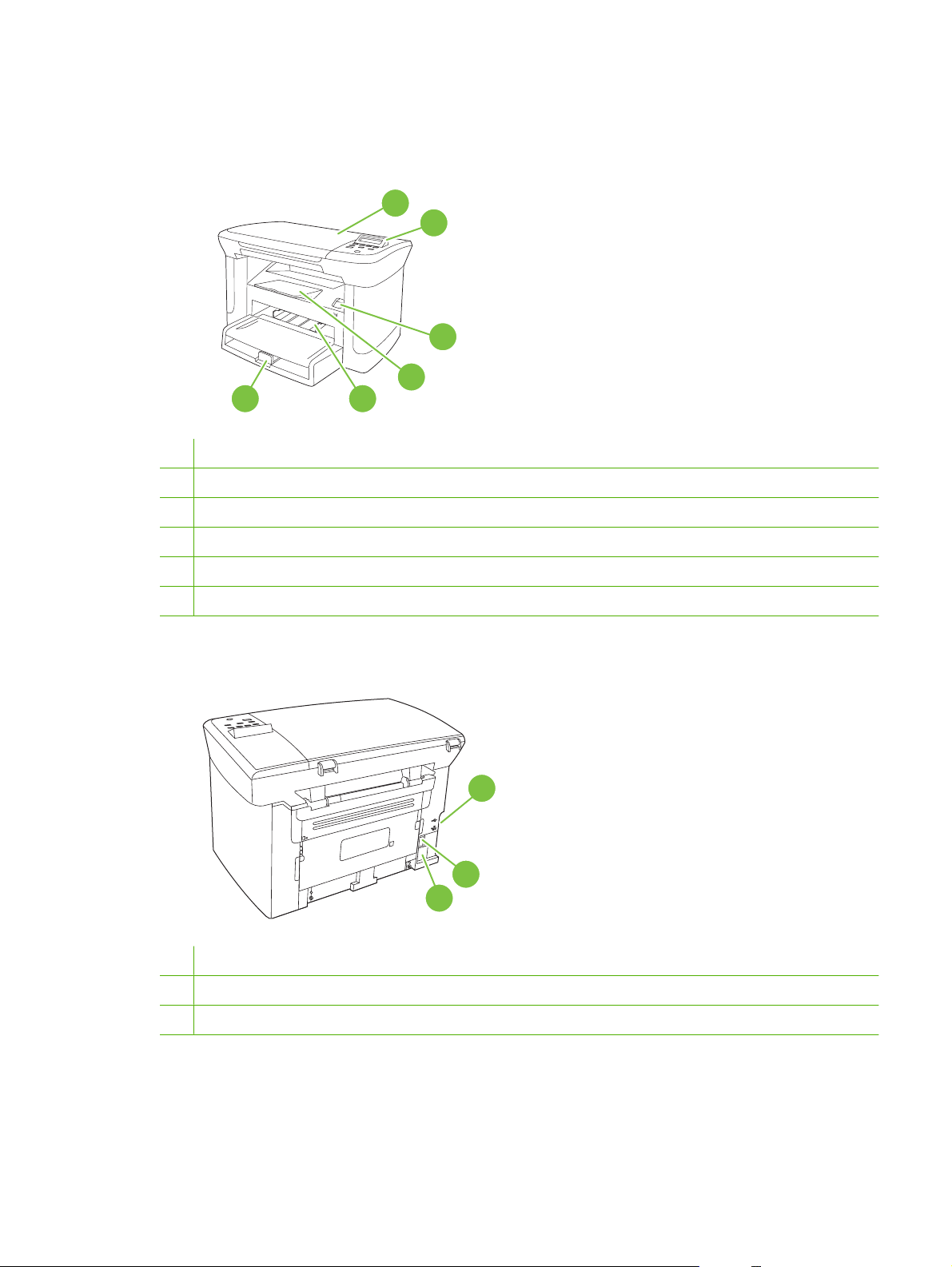
Front view
6
1 Scanner lid
2 Control panel
3 Print-cartridge door latch
4 Output bin
5 Priority input tray
1
2
3
4
5
6 Tray 1
Back view
7 Interface ports
8 Power switch
9 Power connector
7
8
9
ENWW Product walkaround 5
Page 22
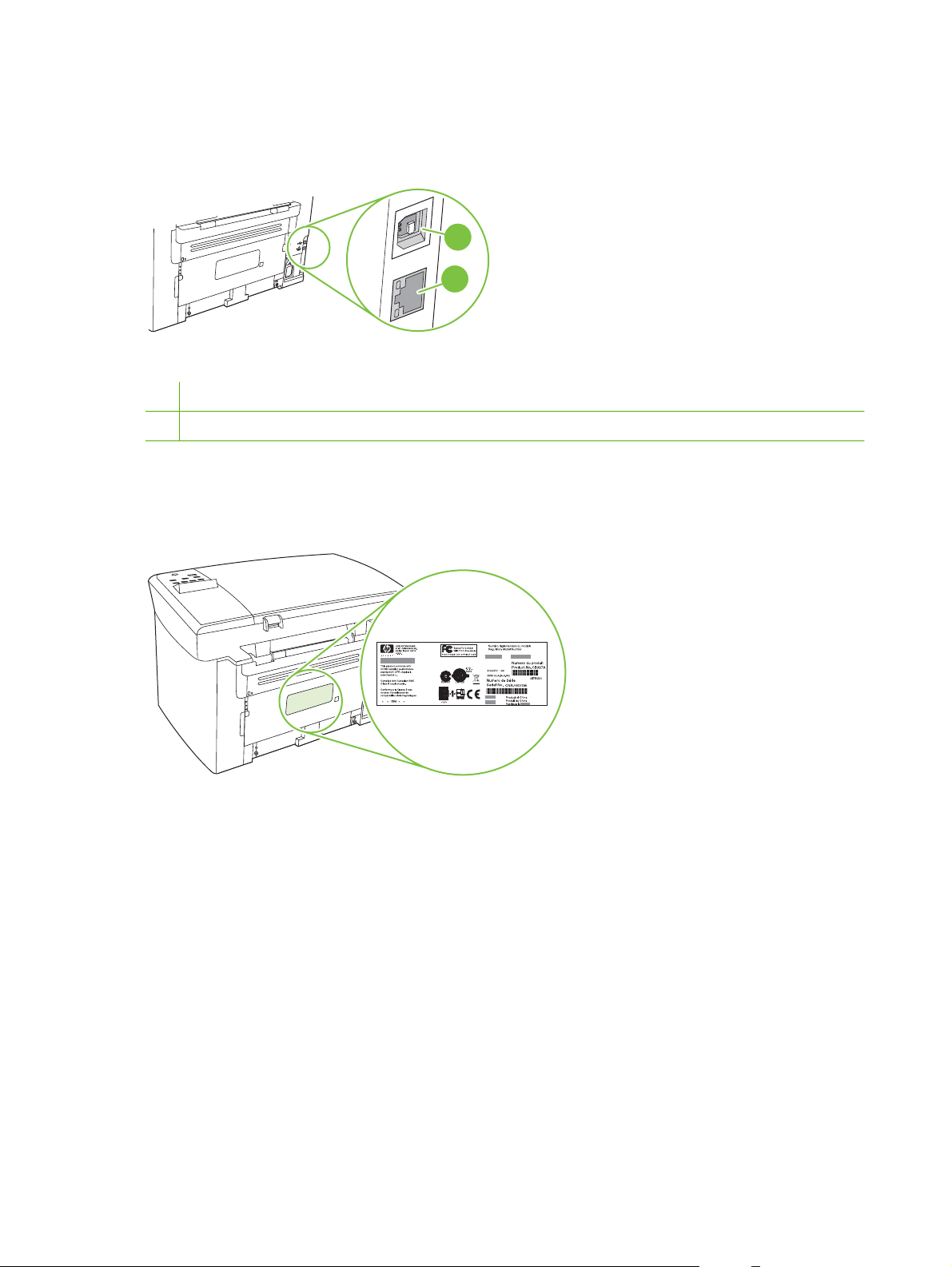
Interface ports
All models have a Hi-Speed USB 2.0 port, and network models also have a 10/100 Base-T Ethernet
port.
1
2
1 Hi-Speed USB 2.0 port
2 Ethernet port (network models only)
Serial number and model number location
The serial number and product model number label is on the rear of the product.
6 Chapter 1 Product information ENWW
Page 23

Software description
Supported operating systems
The product supports the following operating systems:
Full software installation
Windows XP (32-bit)
●
Windows Vista (32-bit)
●
Windows 2000
●
Windows 2003 Server (32-bit)
●
Mac OS X v10.3, v10.4, and later
●
NOTE: For Mac OS X v10.4 and later, PPC and Intel Core Processor Macs are supported.
Supported printer drivers
The product comes with software for Windows and Macintosh that allows the computer to communicate
with the product. This software is called a printer driver. Printer drivers provide access to product
features, such as printing on custom-sized paper, resizing documents, and inserting watermarks.
NOTE: The most recent drivers are available at www.hp.com/support/LJM1120. Depending on the
configuration of Windows-based computers, the installation program for the product software
automatically checks the computer for Internet access in order to obtain the latest drivers.
Software included with the product
Print and scan drivers only
Windows XP (64-bit)
●
Windows Vista (64-bit)
●
Windows 2003 Server (64-bit)
●
There are several options for completing a recommended install. Easy installation will complete the
installation with default settings. Advanced installation allows you to review the license agreements and
the default settings.
Easy installation for Windows
HP drivers
●
Printer driver
◦
Scan driver
◦
HP MFP software
●
HP LaserJet Scan program
◦
Uninstall program
◦
HP Update program
●
HP Customer Participation program
●
ENWW Software description 7
Page 24

Shop for HP Supplies program
●
Other programs
●
Readiris OCR (not installed with other software; separate installation is required)
◦
Advanced installation
Advanced installation includes all of the features that are available with the easy installation. The
HP Customer Participation program is optional.
Macintosh software
HP Product Setup Assistant
●
HP Uninstaller
●
HP LaserJet software
●
HP Scan
◦
HP Director
◦
Scan to e-mail program
◦
HP Photosmart
◦
8 Chapter 1 Product information ENWW
Page 25

Software for Windows
Embedded Web server (network models only)
Network models are equipped with an embedded Web server, which provides access to information
about device and network activities. This information appears in a Web browser, such as Microsoft
Internet Explorer, Netscape Navigator, Apple Safari, or Firefox.
The embedded Web server resides on the device. It is not loaded on a network server.
The embedded Web server provides an interface to the device that anyone who has a networkconnected computer and a standard Web browser can use. No special software is installed or
configured, but you must have a supported Web browser on your computer. To gain access to the
embedded Web server, type the IP address for the device in the address line of the browser. (To find
the IP address, print a configuration page.)
Status Alerts software
The Status Alerts software provides information about the current status of the product.
The software also provides pop-up alerts when certain events occur, such as an empty tray or a problem
with the product. The alert includes information about solving the problem.
Other Windows components and utilities
Software installer — automates the printing system installation
●
Online Web registration
●
ENWW Software for Windows 9
Page 26

Software for Macintosh
Embedded Web server (network models only)
Network models are equipped with an embedded Web server, which provides access to information
about device and network activities. This information appears in a Web browser, such as Microsoft
Internet Explorer, Netscape Navigator, Apple Safari, or Firefox.
The embedded Web server resides on the device. It is not loaded on a network server.
The embedded Web server provides an interface to the device that anyone who has a networkconnected computer and a standard Web browser can use. No special software is installed or
configured, but you must have a supported Web browser on your computer. To gain access to the
embedded Web server, type the IP address for the device in the address line of the browser. (To find
the IP address, print a configuration page.)
HP Director
HP Director is a software program for working with documents. HP Director appears on the computer
screen to initiate scanning, or to change settings on the product through Macintosh Configure Device.
Also included is the HP product Setup Assistant, which sets up the print queue.
10 Chapter 1 Product information ENWW
Page 27

Uninstall software
Windows
1. Click Start, and then click All Programs.
2. Click HP, and then click HP LaserJet M1120.
3. Click Uninstall, and then follow the onscreen instructions to remove the software.
Macintosh
To remove the software, drag the PPD files to the trash can.
ENWW Uninstall software 11
Page 28

Media specifications
Supported paper and print media sizes
This product supports a number of paper sizes, and it adapts to various media.
NOTE: To obtain best print results, select the appropriate paper size and type in the print driver before
printing.
Table 1-2 Supported paper and print media sizes
Size Dimensions Priority input tray Tray 1
Letter 216 x 279 mm (8.5 x 11 in)
Legal 216 x 356 mm (8.5 x 14 in)
A4 210 x 297 mm (8.27 x 11.69 in)
Executive 184 x 267 mm (7.24 x 10.51 in)
A3 297 x 420 mm (11.69 x 16.54 in)
A5 148 x 210 mm (5.83 x 8.27 in)
A6 105 x 148 mm (4.13 x 5.83 in)
B5 (JIS) 182 x 257 mm (7.17 x 10.12 in)
16k 197 x 273 mm (7.75 x 10.75 in)
16k 195 x 270 mm (7.7 x 10.6 in)
16k 184 x 260 mm (7.25 x 10.25 in)
8.5 x 13 216 x 330 mm (8.5 x 13 in)
1
4 x 6
1
5 x 8
10 x 15 cm
Custom Priority input tray: Minimum—76 x 127 mm (3 x
1
These sizes are supported as custom sizes.
1
107 x 152 mm (4 x 6 in)
127 x 203 mm (5 x 8 in)
100 x 150 mm (3.9 x 5.9 in)
5 in); Maximum—216 x 356 mm (8.5 x 14 in)
Table 1-3 Supported envelopes and postcards
Size Dimensions Priority input tray Tray 1
Envelope #10 105 x 241 mm (4.13 x 9.49 in)
Envelope DL 110 x 220 mm (4.33 x 8.66 in)
12 Chapter 1 Product information ENWW
Page 29

Table 1-3 Supported envelopes and postcards (continued)
Size Dimensions Priority input tray Tray 1
Envelope C5 162 x 229 mm (6.93 x 9.84 in)
Envelope B5 176 x 250 mm (6.7 x 9.8 in)
Envelope Monarch 98 x 191 mm (3.9 x 7.5 in)
Postcard 100 x 148 mm (3.94 x 5.83 in)
Double postcard 148 x 200 mm (5.83 x 7.87 in)
Supported paper types and tray capacity
This product has the following tray priority for feeding print media:
1. Priority input tray
2. Tray 1
Minimum media dimensions are 76 x 127 mm (3 x 5 in).
Maximum media dimensions are 216 x 356 mm (8.5 x 14 in).
To obtain the best print results, change the paper size and paper type settings in the printer driver before
printing.
Table 1-4 Supported paper types and tray capacity
Type is Media specifications Priority input tray Tray 1 capacity
Plain
Color
Preprinted
Prepunched
Recycled
Light
Envelopes
Labels Standard 1 sheet Not supported.
Bond
Rough
Transparencies 4 mm (0.1 in) Monochrome
Heavy
Letterhead
1
The maximum stack height for tray 1 is 25 mm (1 inch).
75 g/m2 (20 lb) to 104 g/m2 (27 lb)
60 g/m2 (16 lb) to 75 g/m2 (20 lb)
Less than 90 g/m2 (24 lb)
75 g/m2 (20 lb) to 104 g/m2 (27 lb)
75 g/m2 (20 lb) to 104 g/m2 (27 lb)
Overhead
110 g/m2 (29 lb) to 125 g/m
(33 lb)
2
75 g/m
(20 lb) to 104 g/m2 (27 lb)
Up to 10 sheets Up to 250 sheets
Up to 10 sheets Up to 260 sheets
1 envelope Up to 10 envelopes.
1 sheet Up to 250 sheets
1 sheet Up to 200 sheets
1 sheet Up to 200 sheets.
2
Up to 10 sheets Not supported.
Up to 10 sheets Up to 250 sheets
1
ENWW Media specifications 13
Page 30

14 Chapter 1 Product information ENWW
Page 31

2 Installation
Site preparations
●
What was in the box
●
Install input devices
●
Install supplies
●
ENWW 15
Page 32

Site preparations
Operating environment
Place the product on a sturdy, level surface in a well-ventilated area. Make sure that the air vents are
not blocked and that the product is installed away from direct sunlight, open flames, and ammonia fumes.
Store or install the product in an area that meets the following requirements:
Temperature (printer; operating) 15
●
Temperature (printer; storage) -20
●
Humidity (printer; operating) 10% to 80% relative humidity (no condensation)
●
Humidity (printer; storage) 10% to 90% relative humidity (no condensation)
●
Temperature (toner cartridge; storage) -20
●
Humidity (toner cartridge; storage) 10% to 90% relative humidity (no condensation)
●
o
to 32.5o C (59o to 90.5o F)
o
to 60oC (-4o to 140oF)
o
to 40o C (-4o to 104o F)
16 Chapter 2 Installation ENWW
Page 33

Minimum system requirements
Windows® 2000
●
Windows XP
●
Windows Server 2003
●
Windows Vista
●
Mac OS X v10.3 and later
●
128 MB RAM for Windows operating systems
●
32 MB RAM for Macintosh operating systems
●
250 MB hard-disk space (full installation)
●
CD-ROM drive
●
USB port
●
ENWW Site preparations 17
Page 34

What was in the box
The following components are included in the box.
NOTE: The USB and network cables are not included.
5
2
3
7
6
4
1
Item Description
1 HP LaserJet M1120 MFP
2 Print cartridge
3 Control-panel faceplate (if not already installed)
4 Output bin extension
5 Start guide and support flyer
6 CD-ROMs (software and online user guide)
7 Power cord
8 Tray 1
8
18 Chapter 2 Installation ENWW
Page 35

Install input devices
Priority input tray
The priority input tray is accessed from the front of the product. The product prints from the priority input
tray before attempting to print from tray 1.
Media guides ensure that the media is correctly fed into the product and that the print is not skewed
(crooked on the media). When loading media, adjust the media guides to match the width of the media
that you are using.
ENWW Install input devices 19
Page 36

Tray 1
1. Push tray 1 into the product.
2. Open the tray cover, and then adjust the media guides out.
3. Load the paper in the tray, snug the media guides against the stack, and then close the tray cover.
20 Chapter 2 Installation ENWW
Page 37

Install supplies
Install the print cartridge
1. Open the print-cartridge door.
2. Remove the new print cartridge from its packaging, and then rock the print cartridge back and forth.
3. Remove the orange cover from the print cartridge, and then pull the orange tab straight out to
remove the sealing tape.
ENWW Install supplies 21
Page 38

4. Insert the cartridge into the product until it is firmly in place.
5. Close the print-cartridge door.
22 Chapter 2 Installation ENWW
Page 39

3 Maintenance
Manage supplies
●
Clean the product
●
Management tools
●
ENWW 23
Page 40

Manage supplies
Inspect any parts that wear when servicing the product. Replace them as needed, based on failure or
wear rather than usage.
The following table lists approximate schedules for replacing consumables.
Life expectancies of supplies
Item Capacity
HP LaserJet M1120 MFP Series Recommended maximum of 3,000 pages per month
Print cartridge 2,000 pages1 (standard)
1
For information about the yield for the cartridges, see www.hp.com/go/pageyield. Actual yield depends on specific use.
Check and order supplies
Hewlett-Packard recommends that you place an order for a replacement print cartridge when the Low
message for a print cartridge first appears. Use a new, authentic HP print cartridge to obtain the following
types of supplies information:
Amount of cartridge life remaining
●
Estimated number of pages remaining
●
Number of pages printed
●
Other supplies information
●
Store supplies
Follow these guidelines for storing print cartridges:
Do not remove the print cartridge from its package until you are ready to use it.
●
CAUTION: To prevent damage, do not expose the print cartridge to light for more than a few
minutes.
See
●
Store the supply in a horizontal position.
●
Store the supply in a dark, dry location away from heat and magnetic sources.
●
Environmental specifications on page 187 for operating and storage temperature ranges.
24 Chapter 3 Maintenance ENWW
Page 41

Replace supplies
Print cartridge
1. Open the print-cartridge door.
2. Grasp the handle on the print cartridge, and then pull the cartridge straight out to remove it. See
the recycling information inside the print cartridge box.
3. Remove the new print cartridge from its packaging, and then rock the print cartridge back and forth.
ENWW Manage supplies 25
Page 42

4. Remove the orange cover from the print cartridge, and then pull the orange tab straight out to
remove the sealing tape.
5. Insert the cartridge into the product until it is firmly in place.
6. Close the print-cartridge door.
CAUTION: If toner gets on any clothing, wipe it off with a dry cloth and wash the clothing in cold water.
Hot water sets toner into the fabric.
HP policy on non-HP supplies
Hewlett-Packard Company cannot recommend the use of non-HP supplies, either new or
remanufactured. Because they are not HP products, HP cannot influence their design or control their
quality. Service or repairs required as a result of using a non-HP supply will not be covered under the
warranty.
26 Chapter 3 Maintenance ENWW
Page 43

HP fraud hotline
Call the HP fraud hotline if the product indicates that the print cartridge is not an HP print cartridge and
you think that it is genuine. HP will help determine if the product is genuine and take steps to resolve
the problem.
The print cartridge might not be a genuine HP one if you notice the following issues:
You are experiencing a large number of problems with the print cartridge.
●
The print cartridge does not look like it usually does (for example, the pull tab or the box is different).
●
In the United States, call toll-free: 1-877-219-3183.
Outside the United States, you can call collect. Dial the operator and ask to place a collect call to this
telephone number: 1-770-263-4745. If you do not speak English, a representative at the HP fraud hotline
who speaks your language will assist you. Or, if someone who speaks your language is not available,
a language line interpreter will connect approximately one minute after the beginning of the call. The
language line interpreter is a service that will translate between you and the representative for the HP
fraud hotline.
ENWW Manage supplies 27
Page 44

Clean the product
Clean the exterior
Use a soft, damp, lint-free cloth to wipe dust, smudges, and stains off of the exterior of the product.
Clean the flatbed scanner glass
Dirty glass, from fingerprints, smudges, hair, and so on, slows down performance and affects the
accuracy of special features such as fit-to-page and copy.
1. Turn off the product, unplug the power cord from the electrical outlet, and raise the scanner cover.
2. Clean the glass by using a soft cloth or sponge that has been moistened with nonabrasive glass
cleaner.
CAUTION: Do not use abrasives, acetone, benzene, ammonia, ethyl alcohol, or carbon
tetrachloride on any part of the product; these can damage the product. Do not place liquids directly
on the glass. They might seep under it and damage the product.
Clean the lid backing
Minor debris can accumulate on the white document lid backing that is located underneath the product
lid.
1. Turn off the product, unplug the power cord, and raise the lid.
2. Clean the white document lid backing by using a soft cloth or sponge that has been moistened with
a mild soap and warm water. Wash the backing gently to loosen debris; do not scrub the backing.
28 Chapter 3 Maintenance ENWW
Page 45

3. Dry the backing by using a chamois or soft cloth.
CAUTION: Do not use paper-based wipes because they might scratch the backing.
4. If this does not clean the backing well enough, repeat the previous steps and use isopropyl alcohol
to dampen the cloth or sponge, and then wipe the backing thoroughly with a damp cloth to remove
any residual alcohol.
Clean the paper path
During the printing process, paper, toner, and dust particles can accumulate inside the product. Over
time, this buildup can cause print-quality problems such as toner specks or smearing. This product has
a cleaning mode that can correct and prevent these types of problems.
Specks Smearing
1. Press Setup.
2. Use the arrow buttons to find the Service menu, and then press OK.
3. Use the arrow buttons to find Cleaning mode, and then press OK.
4. Load plain letter or A4 paper when you are prompted.
5. Press OK again to confirm and begin the cleaning process.
A page feeds through the product slowly. Discard the page when the process is completed.
ENWW Clean the product 29
Page 46

Management tools
Information pages
Information pages reside within the product memory. These pages help diagnose and solve problems
with the product.
NOTE: If the product language was not correctly set during installation, you can set the language
manually so the information pages print in one of the supported languages. Change the language by
using the System setup menu on the control panel or the embedded Web server (network models only).
Page description How to print the page
Demo page
Contains examples of text and graphics.
Menu map
Shows the control-panel menus and available settings.
Configuration page
Shows the current settings and product properties.
Embedded Web server
This product is equipped with an embedded Web server (EWS), which provides access to information
about product and network activities. A Web server provides an environment in which web programs
may run, much in the same way that an operating system, such as Windows, provides an environment
for programs to run on a computer. The output from these programs can then be displayed by a Web
browser, such as Microsoft Internet Explorer, Safari, or Netscape Navigator.
1. On the product control panel, press Setup.
2. Use the arrow buttons to select Reports, and then press
OK.
3. Use the arrow buttons to select Demo page, and then
press OK.
1. On the product control panel, press Setup.
2. Use the arrow buttons to select Reports, and then press
OK.
3. Use the arrow buttons to select Menu structure, and then
press OK.
1. On the product control panel, press Setup.
2. Use the arrow buttons to select Reports, and then press
OK.
3. Use the arrow buttons to select Config report, and then
press OK.
An “embedded” Web server resides on a hardware device (such as an HP LaserJet product) or in
firmware, rather than as software that is loaded on a network server.
The advantage of an EWS is that it provides an interface to the product that anyone with a networkconnected product and computer can use. There is no special software to install or configure, but you
must have a supported Web browser on the computer. To gain access to the EWS, type the IP address
for the product in the address line of the browser. (To find the IP address, print a configuration page.)
NOTE: For Macintosh operating systems, you can use the EWS over a USB connection after installing
the Macintosh software included with the product.
30 Chapter 3 Maintenance ENWW
Page 47

Features
The EWS allows you to view product and network status and manage printing functions from a computer.
With the EWS, you can complete the following tasks:
View product status information
●
Determine the remaining life on all supplies and order new ones
●
View and change part of the product configuration
●
View and print some internal pages
●
Select the language in which to display the EWS pages
●
View and change network configuration
●
Set, change, or clear the product security password
●
NOTE: Changing network settings in the EWS might disable some of product software or features.
ENWW Management tools 31
Page 48

32 Chapter 3 Maintenance ENWW
Page 49

4 Operational theory
Basic operation
●
Scanner functions and operation
●
Internal components (base unit)
●
Engine control system
●
Laser/scanner system
●
Pickup/feed/delivery system
●
Image-formation system
●
ENWW 33
Page 50

Basic operation
This chapter presents an overview of the relationships between major components in the product, and
includes a detailed discussion of the image-formation system. The following systems are discussed:
Engine control system
●
Laser/scanner system
●
Pickup/feed/delivery system
●
Image-formation system
●
Figure 4-1 System block diagram
Sequence of operation for the base unit
Operational sequences are controlled by the microprocessor on the DC controller.
Table 4-1 Sequence of operation
Name Timing Purpose
WAIT From power-on until the end of the main-motor initial
drive
STBY (standby) From the end of the WAIT or LSTR period until either
a print command is sent from the formatter or the
power is turned off
INTR (initial
rotation)
From the time of the print command until the pickup
solenoid is turned on
34 Chapter 4 Operational theory ENWW
Detects the presence of a print cartridge; clears
potential from the drum surface and cleans the
transfer roller
Prepares the product to receive print commands
Prepares the photosensitive drum for printing
Page 51

Table 4-1 Sequence of operation (continued)
Name Timing Purpose
PRINT From the end of the INTR period until the primary
high-voltage is turned off
LSTR (last
rotation)
From the end of the PRINT period (when high-voltage
is turned off) until the main motor stops rotating
Table 4-2 Power-on sequence
Step Action
1 Power-on
2 CPU initialization
3 Start video interface communication
4 Check sensors for residual media
5 Main motor initial drive
6
7 Laser/scanner motor initial drive
8 High-voltage control
Fuser heater initial drive. The fuser heater reaches a surface temperature of 100o C.
Forms the image on the photosensitive drum and
transfers the toner image to the media
Delivers the last page of a print job
After LSTR, the product either returns to STBY or, if
another print command was sent from the formatter,
enters INTR.
Detect presence of a print cartridge
Clean the transfer roller after the primary charging AC bias is turned on
9 Failure/abnormality check: detect laser/scanner failure, fuser failure, and open covers
10 Communication with the memory tag
ENWW Basic operation 35
Page 52

Scanner functions and operation
The following sections describe how the document scanner functions.
Scanner functions
The contact image sensor (CIS) is the major component of the optical scanning system. The CIS
consists of three LEDs (red, green, and blue), a light guide, the scanning glass, the rod lens array, and
a sensor array. When the CIS scans a document, the CIS moves and the paper is stationary.
Figure 4-2 Optical system (1 of 2)
The formatter controls the CIS. To begin scanning, the formatter sends a signal to the CIS. The LEDs
illuminate and the light passes through the light guide and scanning glass and strikes the document.
Light that the document reflects passes back through the scanning glass and rod lens array into the
sensor array. The sensor array consists of 5,148 photosensors (468 photosensors on each of 11 sensor
driver circuits). The sensor array collects and amplifies the reflected light and converts it into serial data
in the driver circuits. The CIS sends the data to the formatter for image formation.
36 Chapter 4 Operational theory ENWW
Page 53

Figure 4-3 Optical system (2 of 2)
Scanner operation
At startup and periodically at other times, the scanner assembly moves systematically to locate its home
position. It then calibrates to a white strip located under the glass at the right end of the scan tub.
ENWW Scanner functions and operation 37
Page 54

Internal components (base unit)
Figure 4-4 Cross-section of printer
1 2 3 4
5
6
1 Fuser unit
2 Pressure roller
3 Fuser sleeve
4 Delivery roller
5 Laser/scanner unit
6 Single-sheet-feed slot
7 Multi-purpose tray
8 Photosensitive drum
9 Pickup roller
10 Separation pad
11 Feed roller
12 Transfer roller
789101112
38 Chapter 4 Operational theory ENWW
Page 55

Engine control system
The engine control system coordinates all of the product functions, according to commands sent from
the formatter. It drives the laser/scanner system, the image-formation system, and the pickup/feed/
delivery system.
The engine control system contains the following components:
DC controller
●
Low-voltage power supply
●
High-voltage power supply
●
Fusing control
●
Figure 4-5 Engine control system
ENGINE CONTROL SYSTEM
DC controller
LASER/SCANNER SYSTEM
Formatter
Low-voltage power supply
IMAGE-FORMATION SYSTEM
High-voltage power supply
PICKUP-AND-FEED SYSTEM
Fixing control
ENWW Engine control system 39
Page 56

Figure 4-6 Engine-control-system circuit diagram
Engine controller
Fixing unit
AC input
Transfer roller
Cartridge
Formatter
Fixing control
Low-voltage
power supply
High-voltage
power supply
DC controller
M
Laser/scanner
Motor
Solenoid
Sensor
Switch
unit
40 Chapter 4 Operational theory ENWW
Page 57

Laser/scanner system
The laser/scanner system receives video signals from the DC controller and the formatter, and then
converts the signals into latent images on the photosensitive drum.
Figure 4-7 Laser/scanner system
ENWW Laser/scanner system 41
Page 58

Pickup/feed/delivery system
The pickup/feed/delivery system consists of several types of feed rollers and sensors. The DC controller
uses two motors and two solenoids to drive the rollers. Three media-detection sensors detect media as
it passes through the printer. If media does not reach or pass each sensor within a specified time period,
the DC controller determines that a jam has occurred and alerts the formatter.
The following components are identified in
M1, main motor
●
SL1, pickup solenoid
●
PS701, fuser-delivery sensor
●
PS702, media-width sensor
●
PS751, top-of-page sensor
●
Figure 4-8 Pickup/feed/delivery system
Pressure roller
PS702
Feed roller
PS701
sleeve
Fuser
Photosensitive drum
Figure 4-8 Pickup/feed/delivery system on page 42:
M1
Transfer roller
PS751
SL1
Separation pad
Pickup roller
Single-sheet-feed tray
Multi-purpose tray
42 Chapter 4 Operational theory ENWW
Page 59

Image-formation system
Laser printing requires the interaction of several technologies, including electronics, optics, and
electrophotographics, to produce a printed page. Each process functions independently and must be
coordinated with the other product processes. Image formation consists of the following five processes:
Electrostatic latent-image formation
●
Developing
●
Transfer
●
Fusing
●
Drum cleaning
●
These five processes contain seven steps, which are shown in
on page 43 and described in the following sections.
Figure 4-9 Image-formation system
Step 1: Primary charging
DC and AC biases are applied to the primary charging roller, which transfers a uniform negative potential
to the photosensitive drum.
Figure 4-10 Primary charging
Figure 4-9 Image-formation system
ENWW Image-formation system 43
Page 60

Step 2: Laser beam exposure
The laser beam scans the photosensitive drum to neutralize negative charges on parts of the drum. An
electrostatic latent image is formed on the drum where negative charges were neutralized.
Step 3: Developing
The developing cylinder comes in contact with the photosensitive drum to deposit toner onto the
electrostatic latent image.
NOTE: The charges on the exposed area of the drum are shown as positive in Figure 4-11 Developing
on page 44. The charges are actually negative, but they are more positive than the charges on the
developing cylinder.
Figure 4-11 Developing
Toner acquires a negative charge through friction from the developing cylinder and the blade. When the
negatively charged toner comes in contact with the drum, the toner adheres to the electrostatic latent
image. The image on the drum becomes visible because of the toner.
Step 4: Transfer
The transfer charging roller, to which a DC positive bias is applied, imparts a positive charge on the print
media. When the print media comes in contact with the photosensitive drum, the toner is transferred to
the print media.
44 Chapter 4 Operational theory ENWW
Page 61

Figure 4-12 Transfer
Step 5: Separation
The elasticity of the print media causes its separation from the photosensitive drum. A static-charge
eliminator aids separation by weakening any electrostatic adhesion.
Figure 4-13 Separation
Step 6: Fusing
The DC negative bias applied to the fusing film strengthens the holding force of the toner on the print
media and prevents the toner from scattering.
ENWW Image-formation system 45
Page 62

Figure 4-14 Fusing
Step 7: Drum cleaning
The cleaning blade scrapes the residual toner off of the photosensitive drum and deposits it into the
waste-toner case.
Figure 4-15 Drum cleaning
46 Chapter 4 Operational theory ENWW
Page 63

5 Removal and replacement
Removal and replacement strategy
●
Scanner assembly
●
Product base
●
ENWW 47
Page 64

Removal and replacement strategy
Introduction
●
Before performing service
●
After performing service
●
Post-service tests
●
Parts removal order
●
Introduction
This chapter documents the removal and replacement of field-replaceable units (FRUs) only. Replacing
FRUs is generally the reverse of removal. Occasionally, notes and tips are included to provide directions
for difficult or critical replacement procedures.
HP does not support the repairing of individual subassemblies or troubleshooting at the component
level.
Note the length, diameter, color, type, and location of each screw. Be sure to return each screw to its
original location during reassembly.
Incorrectly routed or loose wire harnesses can interfere with other internal components and can become
damaged or broken. Frayed or pinched harness wires can be difficult to locate. When replacing wire
harnesses, always use the provided wire loops, lance points, or wire-harness guides.
Removal and replacement warnings, cautions, notes, and tips
WARNING! Turn the product off, wait 5 seconds, and then remove the power cord before attempting
to service the product. If this warning is not followed, severe injury can result, as well as damage to the
product. The power must be on for certain functional checks during problem solving. However, the power
supply should be disconnected during parts removal.
Never operate or service the product with the protective cover removed from the laser/scanner
assembly. The invisible reflected beam can damage your eyes.
Sheet-metal and plastic edges in the product can be sharp. Use caution when servicing this product.
CAUTION: Do not bend or fold the flat flexible cables (FFCs) during removal or installation. Also, do
not straighten pre-folds in the FFCs. You must make sure that all FFCs are fully seated in their
connectors. Failure to fully seat an FFC into a connector can cause a short circuit in a PCA.
NOTE: Your product might not appear exactly as the one shown in the photos in this chapter. For
example, the color of the external panels and covers might be different than your product. However, this
does not affect the validity of the procedures in this chapter.
TIP: To install a self-tapping screw, first turn it counterclockwise to align it with the existing thread
pattern, and then carefully turn it clockwise to tighten. Do not overtighten.
48 Chapter 5 Removal and replacement ENWW
Page 65

Electrostatic discharge
CAUTION: The product contains components that are sensitive to electrostatic discharge
(ESD). Always perform service work at ESD-protected workstation. If an ESD-protected workstation is
not available, discharge body static by grasping the print engine chassis before touching an ESDsensitive component. Ground the print engine chassis before servicing the product.
Required tools
#2 Phillips screwdriver with magnetic tip
●
Small flat-blade screwdriver
●
Long flat-blade screwdriver
●
Needle-nose pliers
●
ESD mat (if one is available)
●
Penlight (optional)
●
CAUTION: Always use a Phillips screwdriver (callout 1). Do not use a pozidrive screwdriver (callout 2)
or any motorized screwdriver. These can damage screws or screw threads.
Do not pull directly on the wires to disconnect them. Always pull on the plastic body of a connector to
avoid damaging the connector wires.
Figure 5-1 Phillips and pozidrive screwdriver comparison
Before performing service
If possible, print a configuration page (to record customer settings) and menu map report. See
●
Information pages on page 30.
Remove all media from the product and remove the input tray.
●
Turn off the power by using the power switch.
●
Unplug the power and interface cables.
●
ENWW Removal and replacement strategy 49
Page 66

Place the product on an ESD mat, if one is available. If an ESD-protected workstation is not
●
available, discharge body static and ground the print engine chassis before touching an ESDsensitive part.
Remove the print cartridge. See
●
After performing service
Replace the print cartridge and input tray.
●
Reload the input tray with media.
●
Perform the post-service tests. See
●
Print cartridge on page 25.
Post-service tests on page 51.
50 Chapter 5 Removal and replacement ENWW
Page 67

Post-service tests
After service has been completed, the following tests can be used to verify that the repair or replacement
was successful.
Test 1 (print-quality test)
1. Verify that you have completed the necessary reassembly steps.
2. Ensure that the input tray contains clean, unmarked paper.
3. Attach the power cord and interface cable, and then turn on the product.
4. Verify that the expected start-up sounds occur.
5. Print a configuration page, and then verify that the expected printing sounds occur.
6. Print a demo page, and then verify that the print quality is as expected.
7. Send a print job from the host computer, and then verify that the output meets expectations.
8. If necessary, restore any customer product settings.
9. Clean the outside of the product with a damp cloth.
Test 2 (copy-quality test)
1. Verify that you have completed the necessary reassembly steps.
2. Ensure that the input tray contains clean, unmarked paper.
3. Attach the power cord and interface cable, and then turn on the product.
4. Verify that the expected start-up sounds occur.
5. Print a configuration page, and then verify that the expected printing sounds occur.
6. Place the configuration page on the scanner glass.
7. Print a copy job, and then verify the results.
8. Clean the outside of the product with a damp cloth.
ENWW Removal and replacement strategy 51
Page 68

Parts removal order
Use the following diagrams to determine which parts of the product must be removed before
servicing.
NOTE: The scanner assembly might be contaminated if it is opened outside of a cleanroom
environment. For this reason, the entire scanner assembly is replaceable only as a unit. Replacing the
scanner assembly as an entire assembly replaces the scan module, the scan motor, and the cable.
Figure 5-2 Parts removal order
Flatbed lid
Flatbed lid
Link assemblies
and scanner
support-frame springs
Control-panel overlay
Pr int car tr idge
Media input tr ay
Flatbed lid white plate
Control-panel assembly
Tr ansf er rolle r
Pr inter side co ve rs
Rear co ve r and fuser co ve r
Po wer suppl y
Scanner assembly
Pr int-car tr idge door
Fr ont co ve r
Scanner suppor t-frame
Engine controller uni t
Fuser assembly
Fr ont co ve r
Formatter
Laser/scanner assembly
Main motor
Pic kup assembly
52 Chapter 5 Removal and replacement ENWW
Page 69

Scanner assembly
NOTE: Your product might not appear exactly as the one shown in the photos in this chapter. For
example, the color of the external panels and covers might be different than your product. However, this
does not affect the validity of the procedures in this chapter.
Link assemblies and scanner support-frame spring
1. Push the print-cartridge access button and raise the scanner assembly until it is locked open.
2. Use a small flat-blade screwdriver to release the link tabs on each link assembly.
WARNING! When the link assemblies are disengaged, the scanner assembly can easily fall off
of the product base if it is rotated too far towards the back of the product.
CAUTION: Do not push too hard on the link tabs or the tabs might break.
Figure 5-3 Remove the link assemblies and scanner support-frame spring (1 of 4)
ENWW Scanner assembly 53
Page 70

3. Rotate a link assembly toward the front of the product until the link disengages from the scanner
support frame.
Figure 5-4 Remove the link assemblies and scanner support-frame spring (2 of 4)
4. Remove the link assembly. Repeat these steps to remove the remaining link.
Figure 5-5 Remove the link assemblies and scanner support-frame spring (3 of 4)
54 Chapter 5 Removal and replacement ENWW
Page 71

5. Use needle-nose pliers to remove the scanner support-frame spring.
Figure 5-6 Remove the link assemblies and scanner support-frame spring (4 of 4)
ENWW Scanner assembly 55
Page 72

Scanner lid
1. Open the scanner lid.
2. Lift the scanner lid straight up to remove it from the scanner assembly.
Figure 5-7 Remove the scanner lid (1 of 2)
CAUTION: Avoid touching the flatbed glass. Skin oils and fingerprints can contaminate the glass
and cause print-quality problems.
Figure 5-8 Remove the scanner lid (2 of 2)
56 Chapter 5 Removal and replacement ENWW
Page 73

Control-panel overlay
Carefully pry the outside edge of the control-panel overlay away from the product to remove it.
CAUTION: Be careful to not damage the overlay if it will be reinstalled after servicing the device.
TIP: When installing a replacement control-panel overlay, you can dispose of the barcode part-number
portion of the replacement overlay.
Figure 5-9 Remove the control-panel overlay
ENWW Scanner assembly 57
Page 74

Control-panel assembly
CAUTION: The control-panel is an ESD-sensitive component.
1. Remove the control-panel overlay. See Control-panel overlay on page 57.
2. Remove one screw (callout 1).
Figure 5-10 Remove the control-panel assembly (1 of 3)
1
3. Slide the control panel forward and slightly lift up the control panel.
Figure 5-11 Remove the control-panel assembly (2 of 3)
58 Chapter 5 Removal and replacement ENWW
Page 75

4. Disconnect one FFC (callout 2). Remove the control-panel assembly.
CAUTION: Do not bend or fold the FFCs during the removal or reinstallation process.
Figure 5-12 Remove the control-panel assembly (3 of 3)
2
ENWW Scanner assembly 59
Page 76

Scanner assembly
CAUTION: Avoid touching the flatbed glass. Skin oils and fingerprints can contaminate the glass or
pad and cause print-quality or paper-pickup problems.
1. Remove one screw (callout 1).
Figure 5-13 Remove the scanner assembly (1 of 10)
1
2. Release one tab on the back side of the cover.
Figure 5-14 Remove the scanner assembly (2 of 10)
60 Chapter 5 Removal and replacement ENWW
Page 77

3. Release the bottom tab (callout 2).
Figure 5-15 Remove the scanner assembly (3 of 10)
2
4. Rotate the back side of the cover away from the product, and then slide the cover toward the front
of the product to remove it.
Figure 5-16 Remove the scanner assembly (4 of 10)
1
2
ENWW Scanner assembly 61
Page 78

5. Push the print-cartridge door button to release the scanner assembly, and then raise the assembly
until it locks open.
Figure 5-17 Remove the scanner assembly (5 of 10)
6. Disconnect two FFCs (callout 3; J10 and J12) on the formatter. Remove one FFC from the ferrite
(callout 4).
TIP: It might be easier to thread the FFC through the ferrite by removing one screw and the ferrite
(callout 4).
The ferrite is not captive in the bracket and can be dislodged when you remove the bracket.
Figure 5-18 Remove the scanner assembly (6 of 10)
4
3
62 Chapter 5 Removal and replacement ENWW
Page 79

7. Grasp the tab on the gear-drive arm bracket and carefully flex it away from the scanner assembly
to release the bracket.
Figure 5-19 Remove the scanner assembly (7 of 10)
8. Push the bracket toward the right side of the product until its mounting tabs clear the holes in the
scanner assembly.
Figure 5-20 Remove the scanner assembly (8 of 10)
ENWW Scanner assembly 63
Page 80

9. Use a small flat-blade screwdriver to release the tabs on each link assembly.
WARNING! When the links are disengaged, the scanner assembly can easily fall off of the
product base if it is rotated too far toward the back of the product.
CAUTION: Do not push too hard on the link tabs or the tabs might break.
Figure 5-21 Remove the scanner assembly (9 of 10)
10. Rotate the scanner assembly toward the rear of the product until the rear hinges clear the chassis
hinge pins. Lift the scanner assembly off of the product base.
CAUTION: Make sure that the scanner lid is supported so that it does not swing open when you
remove the scanner assembly.
NOTE: Do not lose the two scanner cushions in the scanner support-frame corners when moving
the product base. See
Scanner cushions on page 70.
Figure 5-22 Remove the scanner assembly (10 of 10)
64 Chapter 5 Removal and replacement ENWW
Page 81

Product base
NOTE: Your product might not appear exactly as the one shown in the photos in this chapter. For
example, the color of the external panels and covers might be different than your product. However, this
does not affect the validity of the procedures in this chapter.
Print cartridge
CAUTION: To prevent damage, do not expose the print cartridge to direct or bright light. Cover it with
a piece of paper.
1. Push the print-cartridge-door release button and raise the scanner assembly until it locks open.
Figure 5-23 Remove the print cartridge (1 of 2)
2. Pull the print cartridge up and out of the product.
Figure 5-24 Remove the print cartridge (2 of 2)
ENWW Product base 65
Page 82

Separation pad
1. Position the product with the rear side facing you.
2. Support the product and tip it forward. Remove two screws (callout 1).
Figure 5-25 Remove the separation pad (1 of 2)
1
3. Remove the separation pad and frame.
Figure 5-26 Remove the separation pad (2 of 2)
66 Chapter 5 Removal and replacement ENWW
Page 83

Pickup roller
1. Remove the print cartridge and locate the pickup roller. See Print cartridge on page 65.
Figure 5-27 Remove the pickup roller (1 of 5)
2. Gently release the small, white tabs on each side of the pickup roller by pushing them away from
the roller, and then rotate the roller away from the mounting frame.
CAUTION: Do not touch the black-sponge transfer roller inside the product. Touching the transfer
roller can damage the product.
Use gentle pressure to release the small white tabs to avoid breaking them.
Figure 5-28 Remove the pickup roller (2 of 5)
ENWW Product base 67
Page 84

3. Gently pull the roller up and out of the product.
Figure 5-29 Remove the pickup roller (3 of 5)
4. Circular and rectangular pegs on each side of the pickup roller fit into corresponding slots on the
pickup-roller mounting frame and prevent the roller from being incorrectly installed. Position the
replacement pickup roller in the slots on the pickup-roller frame.
Figure 5-30 Remove the pickup roller (4 of 5)
68 Chapter 5 Removal and replacement ENWW
Page 85

5. Rotate the top of the pickup roller into position until the white tabs on each side of the roller snap
into place.
Figure 5-31 Remove the pickup roller (5 of 5)
ENWW Product base 69
Page 86

Scanner cushions
1. Open the print-cartridge door.
2. Place a scanner cushion in each well on the scanner support frame (callout 1). Use the eraser-end
of a pencil or use an ink pen with the cap on to seat each cushion in its well.
Figure 5-32 Installing the scanner cushions
1
70 Chapter 5 Removal and replacement ENWW
Page 87

Media input tray
1. Open the media input tray lid.
Figure 5-33 Remove the media input tray (1 of 3)
2. Slide the adjustable media guides to the center of the tray.
Figure 5-34 Remove the media input tray (2 of 3)
ENWW Product base 71
Page 88

3. Depress the pickup-tray locking tabs to release the media input tray, and then pull it out and away
from the product.
Figure 5-35 Remove the media input tray (3 of 3)
72 Chapter 5 Removal and replacement ENWW
Page 89

Transfer roller
CAUTION: Do not touch the black-sponge portion of the transfer roller. Skin oils deposited on the
transfer roller might cause print-quality problems.
1. Open the print-cartridge door and remove the print cartridge.
2. Release the two small tabs on the transfer roller and then slide the roller to the right to release the
left end of the roller shaft. Remove the transfer roller.
Figure 5-36 Remove the transfer roller
ENWW Product base 73
Page 90

Side covers
NOTE: The procedure for removing the right-side and left-side covers is identical. The right-side cover
is shown in the following procedure.
1. Remove one screw (callout 1). Callout 2 is the left-side cover screw.
Figure 5-37 Remove the side covers (1 of 4)
2
1
2. Release the locking tab on the back of the cover.
Figure 5-38 Remove the side covers (2 of 4)
74 Chapter 5 Removal and replacement ENWW
Page 91

3. Release the bottom tab (callout 3).
Figure 5-39 Remove the side covers (3 of 4)
3
4. Slightly rotate the back side of the right cover away from the product, and then slide it toward the
front of the product to release it.
Figure 5-40 Remove the side covers (4 of 4)
2
1
ENWW Product base 75
Page 92

Print-cartridge door
1. Remove the scanner assembly. See Scanner assembly on page 60.
2. Fully open the print-cartridge door and gently pull downward on both print-cartridge swing arms to
release them. (In
is disengaged).
CAUTION: Be careful when releasing the swing arms. They can easily break.
Figure 5-41 Remove the print-cartridge door (1 of 2)
Figure 5-41 Remove the print-cartridge door (1 of 2) on page 76, the left arm
3. Rotate the door toward the back of the product and then lift it up and off of the product.
Figure 5-42 Remove the print-cartridge door (2 of 2)
76 Chapter 5 Removal and replacement ENWW
Page 93

Rear cover and fuser cover
1. Remove the right-side and left-side covers. See Side covers on page 74.
2. Remove one screw (callout 1).
Figure 5-43 Remove the rear cover and fuser cover (1 of 3)
1
3. Release the two rear-cover locking tabs (callout 2). Rotate the bottom of the rear cover up and
away from the product, and then remove it.
Figure 5-44 Remove the rear cover and fuser cover (2 of 3)
2
ENWW Product base 77
Page 94

4. Rotate the bottom of the fuser cover away from the product, and then remove the fuser cover.
Figure 5-45 Remove the rear cover and fuser cover (3 of 3)
78 Chapter 5 Removal and replacement ENWW
Page 95

Front cover
1. Remove the right-side and left-side covers. See Side covers on page 74.
2. Release the lower left-side front-cover locking tab and slightly pry the lower-left corner of the front
cover away from the product.
Figure 5-46 Remove the front cover (1 of 4)
3. Release the lower right-side front-cover locking tab (located near the corner of the power supply)
and slightly pry the lower-right corner of the front cover away from the product.
Figure 5-47 Remove the front cover (2 of 4)
ENWW Product base 79
Page 96

4. Rotate the bottom of the front cover away from the product to release it.
Figure 5-48 Remove the front cover (3 of 4)
5. Remove the front cover.
Figure 5-49 Remove the front cover (4 of 4)
80 Chapter 5 Removal and replacement ENWW
Page 97

Formatter
CAUTION: The formatter is an ESD-sensitive device.
1. Remove the left cover. See Side covers on page 74.
2. Disconnect all FFCs and wire harnesses from the formatter.
3. Remove four screws from the formatter PCA (callout 1). Remove the formatter.
CAUTION: Do not bend or fold the FFCs during the removal or reinstallation process.
NOTE: The scanner assembly is shown removed in this procedure. If the scanner assembly is
installed, there will be additional FFCs connected to the formatter. You do not need to remove the
scanner assembly to remove the formatter.
Figure 5-50 Remove the formatter
1
ENWW Product base 81
Page 98

Power supply
1. Remove the following assemblies:
Right and left covers. See
●
Rear cover and fuser cover. See
●
Front cover. See
●
Formatter. See
●
2. Disconnect one spade connector (callout 1) and remove three screws (callout 2).
Figure 5-51 Remove the power supply (1 of 7)
Front cover on page 79.
Formatter on page 81.
Side covers on page 74.
Rear cover and fuser cover on page 77.
1
2
3. Remove six screws (callout 3) and the sheet-metal plate (callout 4).
Figure 5-52 Remove the power supply (2 of 7)
4
3
2
82 Chapter 5 Removal and replacement ENWW
Page 99

4. Disconnect three FFCs (callout 5) and six wire-harness connectors (callout 6).
CAUTION: Do not bend or fold the FFCs during the removal or reinstallation process.
Figure 5-53 Remove the power supply (3 of 7)
6
6
5
6
6
5. Release the ground wire from the retainer (callout 7) on the product chassis.
NOTE: You might need to slightly pry up on the scanner support frame to release the wire from
the retainer.
Figure 5-54 Remove the power supply (4 of 7)
7
ENWW Product base 83
Page 100

6. Release the wire harness from the retainer (callout 8) on the power supply.
Figure 5-55 Remove the power supply (5 of 7)
8
7. Unclip two clips (callout 9) and remove one plastic bracket (callout 10).
CAUTION: The wire harness (callout 11) attached to the bracket is not captive. Do not lose this
wire harness when the bracket is removed.
Figure 5-56 Remove the power supply (7 of 7)
10
11
9
84 Chapter 5 Removal and replacement ENWW
 Loading...