

Page 1
hp color LaserJet
3500/3550 and 3700
series printer
service
Page 2

Page 3

HP Color LaserJet 3500/3550 and 3700
series printers
Service Manual
Page 4

© 2004 Copyright Hewlett-Packard
Development Company, L.P.
Reproduction, adaptation or translation
without prior written permission is
prohibited, except as allowed under the
copyright laws.
The information contained herein is subject
to change without notice.
The only warranties for HP products and
services are set forth in the express
warranty statements accompanying such
products and services. Nothing herein
should be construed as constituting an
additional warranty. HP shall not be liable
for technical or editorial errors or omissions
contained herein.
Part number: Q5990-90939
Edition 1, 10/2004
Trademark Credits
Microsoft® is a U.S. registered trademark
of Microsoft Corporation.
MS-DOS® is a U.S. registered trademark
of the Microsoft Corporation.
*Pantone®, Inc.'s check-standard
trademark for color.
PostScript® is a trademark of Adobe
Systems Incorporated.
TrueType
TM
is a U.S. trademark of Apple
Computer, Inc.
UNIX® is a registered trademark of The
Open Group.
Windows, MS Windows, and Windows NT
are U.S. registered trademarks of Microsoft
Corporation.
Page 5

Conventions
This manual uses the following conventions:
Color is used to emphasize items that are important to the material under discussion.
Bold is used for menu items to click and for emphasis, particularly in situations where italic
type would be confusing.
Italic type is used to indicate related documents or emphasis.
DISPLAY type indicates text as seen on the printer control panel display.
Commands you use on a computer keyboard or on the printer control panel are shown in
ENU
and S
TOP
Keycap. Two examples are M
.
COURIER type indicates text that you type on a computer keyboard exactly as shown.
NOTE
CAUTION
WARNING!
Notes contain important information set off from the text.
Caution messages alert you to the possibility of damage to equipment or loss of data.
Warning messages alert you to the possibility of personal injury.
ENWW Conventions iii
Page 6

iv ENWW
Page 7

Table of contents
1 Printer description
Chapter contents .......................................................................................................................1
Printer configurations ................................................................................................................3
HP Color LaserJet 3500/3550 printer .................................................................................3
HP Color LaserJet 3500n/3550n printer .............................................................................3
HP Color LaserJet 3700 printer ..........................................................................................4
HP Color LaserJet 3700n printer ........................................................................................4
HP Color LaserJet 3700dn printer ......................................................................................5
HP Color LaserJet 3700dtn printer .....................................................................................5
Printer features ..........................................................................................................................6
Printer assemblies .....................................................................................................................9
Front and rear features .......................................................................................................9
Site requirements ....................................................................................................................11
Space requirements .........................................................................................................11
Electrical specifications ....................................................................................................12
Environmental specifications ............................................................................................13
Printer specifications ...............................................................................................................15
Duty cycle .........................................................................................................................15
Print media specifications .......................................................................................................16
Supported media weights and sizes .................................................................................16
Hewlett-Packard warranty statement ......................................................................................19
HP's Premium Protection Print Cartridge Warranty Limited Warranty Statement ..................20
Premium Protection Warranty Color LaserJet Image Fuser Kit and Image Transfer
Kit Limited Warranty Statement ...........................................................................................21
Identification ............................................................................................................................22
Model and serial numbers ................................................................................................22
Power and regulatory information ....................................................................................22
Selecting paper .......................................................................................................................24
Paper to avoid ...................................................................................................................24
Paper that can damage the printer ...................................................................................24
Printing on special media ........................................................................................................26
Transparencies .................................................................................................................2 6
Glossy paper .....................................................................................................................26
Colored paper ...................................................................................................................26
Envelopes .........................................................................................................................27
Labels ...............................................................................................................................27
Heavy paper .....................................................................................................................28
HP LaserJet Tough paper ................................................................................................28
Preprinted forms and letterhead .......................................................................................28
Recycled paper .................................................................................................................29
Media weight .....................................................................................................................29
Environmental product stewardship program .........................................................................31
Protecting the environment ...............................................................................................31
Declaration of Conformities .....................................................................................................34
Safety statements ...................................................................................................................37
Laser safety statement .....................................................................................................37
ENWW Conventions v
Page 8

Canadian DOC regulations ...............................................................................................37
EMI statement (Korea) .....................................................................................................37
VCCI statement (Japan) ...................................................................................................37
Laser statement for Finland ..............................................................................................38
FCC Regulations .....................................................................................................................39
2 Service approach
Chapter contents .....................................................................................................................41
Search approach .....................................................................................................................42
Parts and supplies ...................................................................................................................43
Ordering parts ...................................................................................................................43
Ordering supplies ..............................................................................................................43
Exchange program ...........................................................................................................44
Supplies ............................................................................................................................44
World Wide Web ...............................................................................................................44
HP service parts information CD-ROM ............................................................................44
HP support assistant CD-ROM ........................................................................................44
Customer care reseller sales and service support center ................................................44
Ordering related documentation and software .................................................................45
HP maintenance agreements .................................................................................................46
On-site service agreements ..............................................................................................46
3 Installation and configuration
Chapter contents .....................................................................................................................47
Checking the package contents ..............................................................................................48
Unpacking the printer ..............................................................................................................50
Installing the print cartridge .....................................................................................................55
Loading paper into Tray 3 (optional) .......................................................................................57
Loading paper into Tray 2 .......................................................................................................59
Loading paper into Tray 1 (optional procedure) ......................................................................61
Connecting power ...................................................................................................................62
Installing a new control panel overlay (optional) .....................................................................63
Testing the printer operation ...................................................................................................64
Using PowerSave Time ...........................................................................................................65
To set PowerSave Time ...................................................................................................65
To disable/enable PowerSave ..........................................................................................65
USB configuration ...................................................................................................................66
Connecting the USB cable ...............................................................................................66
Parallel configuration (HP Color LaserJet 3700 series printer only) .......................................67
Network configuration .............................................................................................................68
Enhanced I/O (EIO) configuration (HP color LaserJet 3700 series printer only) ....................69
HP Jetdirect print servers .................................................................................................69
Available enhanced I/O interfaces ....................................................................................69
NetWare networks ............................................................................................................70
Windows and Windows NT networks ...............................................................................70
AppleTalk networks ..........................................................................................................70
UNIX/Linux networks ........................................................................................................70
Printer software .......................................................................................................................71
Printer drivers ...................................................................................................................71
Software for networks .......................................................................................................72
Utilities ..............................................................................................................................73
Setting security on the printer .................................................................................................76
Locking the control panel ..................................................................................................76
Using an ASCII PJL escape sequence to set security .....................................................77
Printer memory for the HP Color LaserJet 3700 series printer ...............................................78
vi ENWW
Page 9

Installing memory and font DIMMs .........................................................................................79
Enabling memory ..............................................................................................................83
Enabling the language font DIMM (HP color LaserJet 3700 only) ...................................83
Checking DIMM installation (HP color LaserJet 3700 only) .............................................84
Installing an HP Jetdirect print server card in the HP color LaserJet 3700 series printer ......85
To install the HP Jetdirect print server card .....................................................................85
Installing an HP Jetdirect en3700 external print server ..........................................................88
4 Printer maintenance
Chapter contents .....................................................................................................................91
Cleaning the printer and accessories ......................................................................................92
Cleaning spilled toner .......................................................................................................92
Managing supplies ..................................................................................................................94
Supplies life ......................................................................................................................94
Approximate replacement intervals for supplies for the HP Color LaserJet 3500
series printer ..................................................................................................................94
Approximate replacement intervals for supplies for the HP Color LaserJet
3550/3700 series printer ................................................................................................94
Locating supplies and parts ....................................................................................................96
Replacing supply items ...........................................................................................................97
Replacing the transfer unit ................................................................................................99
Replacing the fuser and pickup roller .............................................................................103
5 Theory of operation
Chapter contents ...................................................................................................................113
Basic operation .....................................................................................................................114
Operation sequence .......................................................................................................114
Power-on sequences ......................................................................................................116
Engine control system ...........................................................................................................119
DC controller PCB ..........................................................................................................119
Low-voltage power supply circuit ...................................................................................126
Low-voltage power supply circuit ...................................................................................131
Laser/scanner system ...........................................................................................................139
Laser control ...................................................................................................................140
Scanner motor control ....................................................................................................144
Image formation system ........................................................................................................146
Print process ...................................................................................................................147
Developing section .........................................................................................................156
Cartridge cleaning control ...............................................................................................163
Transfer section ..............................................................................................................164
ITB cleaning control ........................................................................................................167
Waste toner full detection ...............................................................................................167
Transfer (ITB) unit detection ...........................................................................................168
Transfer unit life detection ..............................................................................................169
ITB self-aligning mechanism ..........................................................................................170
Primary transfer roller engaging/disengaging control ....................................................171
Secondary transfer roller engaging/disengaging control ................................................172
Secondary transfer roller engaging/disengaging detection ............................................173
Color misregistration control ...........................................................................................174
Image stabilization control ..............................................................................................177
Pickup/feed system ...............................................................................................................182
Pickup/feed unit ..............................................................................................................184
Fuser/delivery unit ..........................................................................................................189
Duplexing feed unit (HP 3700 printer only) ....................................................................192
Jam detection .................................................................................................................195
ENWW Conventions vii
Page 10

Paper feeder ..........................................................................................................................197
Pickup/delivery sequence ...............................................................................................198
Paper jam detection ........................................................................................................199
6 Removal and replacement
Chapter contents ...................................................................................................................201
Introduction ............................................................................................................................204
Removal and replacement strategy ................................................................................204
Repair notices .................................................................................................................204
Caution regarding electrostatic discharge (ESD) ...........................................................204
Required tools .................................................................................................................204
Types of screws ..............................................................................................................205
Supplies .................................................................................................................................207
Print cartridges and transfer unit ....................................................................................208
Covers ...................................................................................................................................209
Front door removal .........................................................................................................209
Left cover removal ..........................................................................................................210
Left front cover removal ..................................................................................................211
Right cover removal ........................................................................................................213
Top cover removal ..........................................................................................................214
Upper rear door removal ................................................................................................214
Rear cover removal ........................................................................................................215
Lower rear door (rear output bin) removal .....................................................................215
Tray 1 (multipurpose) removal .......................................................................................216
Main Assemblies ...................................................................................................................217
Transfer unit removal ......................................................................................................218
Print cartridge removal ...................................................................................................219
Fuser removal .................................................................................................................220
Face-down delivery assembly removal ..........................................................................221
Laser/scanner assembly removal ...................................................................................222
Image drive assembly removal .......................................................................................223
Developing engaging drive assembly removal ...............................................................225
Pick-up/feed assembly removal .....................................................................................225
Main assembly parts .............................................................................................................236
Tray 1 pick-up roller removal ..........................................................................................237
Tray 1 separation pad removal .......................................................................................237
Tray 2 pick-up roller removal ..........................................................................................238
Tray 2 separation pad removal .......................................................................................238
Secondary transfer charging roller removal ...................................................................239
Fuser sleeve unit removal ..............................................................................................239
Pressure roller removal ..................................................................................................239
Main thermistor/sub-thermistor removal .........................................................................239
Thermoswitch removal ...................................................................................................239
Feed guide unit removal .................................................................................................240
Swing guide removal, right .............................................................................................242
Swing guide removal, left ...............................................................................................245
Switches ................................................................................................................................250
Door Switch (SW1) removal ...........................................................................................250
Test print switch (SW1001) removal ..............................................................................251
Power switch (SW3001) removal ...................................................................................251
Sensors .................................................................................................................................252
Tray 1 (multipurpose tray) paper sensor (PS1) removal ................................................253
Tray 2 (cassette) paper sensor (PS2) removal ..............................................................253
Registration paper sensor (PS4) removal ......................................................................254
Media sensor (PS5) removal ..........................................................................................255
viii ENWW
Page 11

Fuser front paper sensor (PS6) removal ........................................................................256
Fuser delivery paper sensor (PS7) removal ...................................................................256
Face-down delivery paper sensor (PS8) removal ..........................................................257
Reversed paper sensor (PS9) removal (HP 3700 only) .................................................257
Duplex feed delivery paper sensor (PS10) removal (HP 3700 only) .............................258
Rear output bin paper sensor (PS11) removal ...............................................................259
Color misregistration sensor (PS12) removal ................................................................260
Waste toner level sensor (PS13) removal ......................................................................260
Developing engaging sensor (PS14) removal ................................................................261
Environment sensor (PS15) removal .............................................................................261
Secondary transfer roller engaging sensor (PS16) removal ..........................................262
Solenoids and Clutches ........................................................................................................263
Tray 1 (multipurpose tray) pick-up solenoid (SL1) removal ...........................................263
Tray 2 pick-up solenoid (SL2) removal ...........................................................................264
Secondary transfer roller engaging solenoid (SL4) removal ..........................................265
Duplex feed solenoid (SL5) removal (HP 3700 only) .....................................................266
Registration clutch (CL1) removal ..................................................................................266
Black (K) development clutch (CL2 - image drive) removal ...........................................267
Developing engaging drive clutch (CL3) removal ..........................................................268
Motor and fans ......................................................................................................................269
Feed motor (M1) removal ...............................................................................................269
Delivery motor (M2) removal ..........................................................................................271
Drum motor (M3) removal ..............................................................................................271
Developing motor (M4) removal .....................................................................................273
Primary transfer roller engaging motor (M5) removal ....................................................274
Exhaust fan (FAN1) removal ..........................................................................................277
Circuit Boards ........................................................................................................................278
DC controller PCB removal ............................................................................................278
Formatter PCB removal ..................................................................................................279
High-voltage power supply PCB removal .......................................................................281
Low-voltage power supply PCB removal .......................................................................285
Memory controller PCB removal ....................................................................................286
Control Panel PCB removal ............................................................................................287
Miscellaneous parts ..............................................................................................................288
Swing rod guide, left removal .........................................................................................288
Swing rod/lock guide, right removal ...............................................................................288
Transfer contact assembly removal ...............................................................................288
Developing contact assembly .........................................................................................288
Tray 2 (cassette) parts removal ............................................................................................291
Tray 2 (cassette) .............................................................................................................291
Cassette (Tray 2) guide, right, removal ..........................................................................291
500-Sheet paper feeder (Tray 3) covers ...............................................................................296
Front cover removal - 500-sheet paper feeder ...............................................................296
Right cover removal - 500-sheet paper feeder ...............................................................297
Left cover removal - 500-sheet paper feeder .................................................................297
500-Sheet paper feeder internal parts ..................................................................................298
Pick-up roller removal - 500-sheet paper feeder ............................................................298
Separation pad removal - 500-sheet paper feeder ........................................................299
Pick-up drive unit removal - 500-sheet paper feeder .....................................................299
500-Sheet paper feeder sensor/solenoid/motor/PCB ...........................................................300
500-Sheet paper feeder PCB removal - 500-sheet feeder ............................................300
Pick-up clutch (CL4) removal - 500-sheet feeder ...........................................................301
Pick-up solenoid (SL3) removal - 500-sheet feeder .......................................................301
Paper sensor (PS3) removal - 500-sheet feeder ...........................................................302
ENWW Conventions ix
Page 12

7 Troubleshooting
Chapter contents ...................................................................................................................303
Introduction ............................................................................................................................306
Troubleshooting process .......................................................................................................307
Pre-troubleshooting checklist .........................................................................................307
Troubleshooting flowchart ..............................................................................................308
Troubleshooting power-on ..............................................................................................310
Printer error troubleshooting .................................................................................................312
Status messages ............................................................................................................312
Warning messages .........................................................................................................312
Error messages ..............................................................................................................312
Critical error messages ...................................................................................................312
Alphabetical printer messages .......................................................................................312
Numerical printer messages ...........................................................................................327
Replacement parts configuration ..........................................................................................352
Formatter and DC Controller replaced at the same time ...............................................352
Formatter (New) replacement configuration ...................................................................352
Formatter (previously installed in another printer) replacement configuration ...............353
DC Controller (New) replacement configuration ............................................................353
DC Controller (previously installed in another printer) replacement configuration ........354
Media sensor (PS5) replacement configuration .............................................................354
Color Misregistration Sensor (PS12) replacement configuration ...................................355
Laser/scanner Assembly replacement configuration .....................................................355
Fuser replacement configuration ....................................................................................355
Transfer unit (ITB assembly) replacement configuration ...............................................355
Paper path troubleshooting ...................................................................................................356
Paper path jam areas .....................................................................................................357
Paper jam error message ...............................................................................................357
Paper path areas jam troubleshooting ...........................................................................360
Paper jam recovery feature ............................................................................................377
Avoiding paper jams .......................................................................................................377
General paper path troubleshooting ...............................................................................379
Persistent jams ...............................................................................................................380
Image formation troubleshooting ..........................................................................................381
Print quality problems associated with media ................................................................381
Overhead transparency defect .......................................................................................381
Print quality problems associated with the environment ................................................382
Print quality problems associated with paper jams ........................................................382
Print quality problems associated with toner buildup .....................................................382
Print quality troubleshooting pages ................................................................................383
Calibrating the printer .....................................................................................................383
Using Color ...........................................................................................................................384
HP ImageREt 2400 .........................................................................................................384
Paper selection ...............................................................................................................384
Color options (available for the HP Color LaserJet 3700 series printer) ........................384
Standard red-green-blue (sRGB) ...................................................................................384
Printing in four-colors [CMYK (available for the HP Color LaserJet 3700 series
printer) .........................................................................................................................385
CMYK ink set emulation (PostScript only) .....................................................................385
Managing color ......................................................................................................................386
Print in Grayscale ...........................................................................................................386
Automatic or manual color adjustment ...........................................................................386
Manual color options ......................................................................................................386
Matching colors .....................................................................................................................388
Swatch book color matching (HP Color LaserJet 3700 series printer only) ...................388
Adjusting color balance ..................................................................................................389
x ENWW
Page 13

Image defects ........................................................................................................................390
Light image ....................................................................................................................391
Light color .......................................................................................................................392
Dark image ...................................................................................................................392
Dark color .......................................................................................................................393
Completely blank image .................................................................................................393
All black or solid color ....................................................................................................393
Dots in vertical lines .......................................................................................................394
Dirt on back of paper ......................................................................................................394
Dirt on front of paper .......................................................................................................394
Vertical lines ..................................................................................................................395
White vertical lines ..........................................................................................................395
Horizontal line .................................................................................................................396
White horizontal line .......................................................................................................396
Color missing ..................................................................................................................397
Blank spots .....................................................................................................................397
Poor fusing ....................................................................................................................397
Image distortion ..............................................................................................................398
Color misregistration .......................................................................................................398
Smearing ........................................................................................................................399
Misplaced image .............................................................................................................399
Reversed color ................................................................................................................400
Snail tracks .....................................................................................................................400
Repetitive defects troubleshooting ........................................................................................401
Interface troubleshooting ......................................................................................................403
Communications checks .................................................................................................403
EIO troubleshooting ........................................................................................................403
AUTOEXEC.BAT standard configurations .....................................................................404
Printer Job Language (PJL) commands .........................................................................404
@PJL COMMENT ..........................................................................................................405
@PJL INFO CONFIG .....................................................................................................405
@PJL INFO ID ................................................................................................................405
@PJL INFO USTATUS ..................................................................................................405
@PJL INFO PAGECOUNT ............................................................................................405
@PJL JOB ......................................................................................................................406
@PJL EOJ ......................................................................................................................406
@PJL ECHO ...................................................................................................................406
@PJL USTATUS JOB=ON/OFF ....................................................................................406
@PJL USTATUSOFF .....................................................................................................406
Control panel troubleshooting ...............................................................................................407
Printing a menu map ......................................................................................................407
Information menu ............................................................................................................407
Paper handling menu .....................................................................................................408
Configure device menu ...................................................................................................409
Print quality menu ...........................................................................................................411
System setup menu ........................................................................................................414
I/O menu .........................................................................................................................418
Resets menu ...................................................................................................................419
Diagnostics menu ...........................................................................................................419
Service menu ..................................................................................................................420
Tools for troubleshooting ......................................................................................................422
Embedded Web server (HP Color LaserJet 3700 series printer only) ...........................422
HP Toolbox .....................................................................................................................424
Printer configuration page ..............................................................................................428
Supplies status page ......................................................................................................429
Usage page (HP 3700 only) ...........................................................................................430
ENWW Conventions xi
Page 14

Event log .........................................................................................................................431
Diagnostics ............................................................................................................................433
Diagnostics flowchart ......................................................................................................433
Engine diagnostics .........................................................................................................434
Diagnostics from the Control Panel ......................................................................................436
Printer display menu .......................................................................................................436
Diagnostics test menu ....................................................................................................436
Paper Path Test ..............................................................................................................439
Component Test – special mode test .............................................................................439
Print/Stop Test ................................................................................................................442
Information menu ............................................................................................................443
Configure device menu/printing menu ............................................................................443
Configure device menu/resets menu ..............................................................................443
Configure device menu/print quality menu .....................................................................443
Test pages .............................................................................................................................445
Engine test page .............................................................................................................445
Formatter test page ........................................................................................................445
Engine resets ........................................................................................................................446
Cold reset .......................................................................................................................446
NVRAM initialization .......................................................................................................446
Calibration bypass ..........................................................................................................447
Calibrate Now .................................................................................................................447
Service menu ........................................................................................................................448
Accessing the Service menu ..........................................................................................448
Diagrams ...............................................................................................................................450
Main parts .......................................................................................................................451
Switches .........................................................................................................................452
Sensors ...........................................................................................................................453
Solenoids and clutches ...................................................................................................454
Motors and fans ..............................................................................................................455
PCBs ...............................................................................................................................456
Connector locations ........................................................................................................458
500-sheet paper feeder connectors ...............................................................................462
General circuit diagram ..................................................................................................463
8 Parts and diagrams
Chapter contents ...................................................................................................................465
Introduction ............................................................................................................................466
Ordering parts .......................................................................................................................467
Supplies and accessories ...............................................................................................467
Replacement parts configuration ....................................................................................473
Illustrations and parts lists .....................................................................................................478
Alphabetical parts list.............................................................................................................538
Numerical parts list.................................................................................................................551
Index
xii ENWW
Page 15

List of tables
Table 1-1. Features ............................................................................................................6
Table 1-2. Electrical specifications ...................................................................................12
Table 1-3.
Table 1-4. Environmental specifications ..........................................................................13
Table 1-5. Supply storage requirements ..........................................................................13
Table 1-6. Physical dimensions ........................................................................................15
Table 1-7. Acoustic emissions ..........................................................................................15
Table 1-8.
Table 1-9.
Table 1-10.
Table 1-11. Automatic two-sided printer (available on some models of the
Table 1-12. Model names and numbers ............................................................................22
Table 1-13. Weight equivalence table ................................................................................29
Table 2-1. Related documentation and software .............................................................45
Table 3-1. Printer drivers for the HP Color LaserJet 3500/3550 series printer ................71
Table 3-2. Printer drivers for the HP Color LaserJet 3700 series printer .........................72
Table 3-3. Other software applications ............................................................................75
Table 3-4. Printer security levels ......................................................................................76
Table 4-1. Cleaning the printer .........................................................................................92
Table 4-2. Approximate replacement intervals .................................................................94
Table 4-3. Approximate replacement intervals .................................................................95
Table 5-1. Basic operation sequence .............................................................................115
Table 5-2. Motor Functions ............................................................................................122
Table 5-3. Function of solenoids ....................................................................................123
Table 5-4. Function of clutches ......................................................................................123
Table 5-5. Print media and feed speeds ........................................................................187
Table 5-6. Conditions of available duplex feed ..............................................................195
Table 6-1. Common fasteners ........................................................................................205
Table 6-2. Approximate replacement intervals for print cartridges ................................207
Table 6-3. Approximate replacement intervals for supply items ....................................207
Table 7-1. Pre-troubleshooting checklist ........................................................................307
Table 7-2. Alphabetical printer messages ......................................................................313
Table 7-3. Numerical printer messages .........................................................................328
Table 7-4. Error messages and associated jam locations .............................................358
Table 7-5. Causes for multiple pages feeding ................................................................360
Table 7-6. Causes for jams in the Tray 1 pick-up area ..................................................360
Table 7-7. Causes for jams in the Tray 2 area ...............................................................361
Table 7-8. Causes for jams in the fuser/face-down delivery area ..................................361
Table 7-9. Transfer/feed area .........................................................................................362
Table 7-10. Causes for wrinkled or folded paper (paper path entrance) .........................368
Table 7-11. Causes for wrinkled or folded paper (paper path exit) ..................................368
Table 7-12. Causes for skewed paper .............................................................................368
Table 7-13. Causes for jams in the duplex area (HP 3700 (only) ....................................369
Table 7-14. Fuser/face-down delivery area ......................................................................370
Table 7-15. Common causes of paper jams ....................................................................378
Power consumption for 110 and 220-volt (average in watts)
1
Tray 1 paper sizes
Tray 2 paper sizes
Tray 3 paper sizes
HP Color LaserJet 3700 series printer)
.........................................................................................16
1
.........................................................................................17
1
.........................................................................................17
1
.........................................................17
1
........................12
ENWW Conventions xiii
Page 16

Table 7-16. Image defects ................................................................................................390
Table 7-17. Causes for light images .................................................................................391
Table 7-18. Causes for one color printing light ................................................................392
Table 7-19. Causes for dark images ................................................................................392
Table 7-20. Causes for one color printing dark ................................................................393
Table 7-21. Causes for a completely blank image ...........................................................393
Table 7-22. Causes for an all black or solid colored image .............................................393
Table 7-23. Causes for vertical lines of white dots ..........................................................394
Table 7-24. Causes for dirt on the back of the paper .......................................................394
Table 7-25. Causes for dirt on the front of the paper .......................................................395
Table 7-26. Causes for vertical lines ................................................................................395
Table 7-27. Causes for white vertical lines ......................................................................395
Table 7-28. Causes for horizontal line .............................................................................396
Table 7-29. Causes for white horizonal lines ...................................................................396
Table 7-30. Causes for a missing color ............................................................................397
Table 7-31. Causes for blank spots ..................................................................................397
Table 7-32. Causes for poor fusing ..................................................................................397
Table 7-33. Causes for distortion or blurring ....................................................................398
Table 7-34. Causes for smearing .....................................................................................398
Table 7-35. Causes for smearing .....................................................................................399
Table 7-36. Causes for a misplaced image ......................................................................399
Table 7-37. Causes for reversed color .............................................................................400
Table 7-38. Causes for reversed color .............................................................................400
Table 7-39. Repetitive defect cause .................................................................................401
Table 7-40. Communications check .................................................................................403
Table 7-41. Information menu ..........................................................................................408
Table 7-42. Paper handling menu ....................................................................................408
Table 7-43. Printing menu ................................................................................................409
Table 7-44. Print quality menu .........................................................................................412
Table 7-45. System setup submenu .................................................................................415
Table 7-46. I/O submenu ..................................................................................................418
Table 7-47. Resets submenu ...........................................................................................419
Table 7-48. Diagnostics menu ..........................................................................................419
Table 7-49. Service menu ................................................................................................420
Table 7-50. Paper path and manual sensor test control panel information .....................438
Table 8-1. Supplies and accessories .............................................................................467
Table 8-2. Common fasteners ........................................................................................472
Table 8-3. PCB locations ................................................................................................481
Table 8-4. Paper feeder PCB Assembly Location diagram ...........................................483
Table 8-5. External covers and panels ...........................................................................485
Table 8-6. Front door assembly .....................................................................................487
Table 8-7. Internal components (1 of 4) .........................................................................489
Table 8-8. Internal components (2 of 4) .........................................................................491
Table 8-9. Internal components (3 of 4) .........................................................................495
Table 8-10. Internal components (4 of 4) .........................................................................497
Table 8-11. Center Frame Assembly ...............................................................................499
Table 8-12. Main Right Side Plate Assembly / Motors .....................................................501
Table 8-13. Main Left Side Plate Assembly .....................................................................505
Table 8-14. Image drive assembly ...................................................................................511
Table 8-15. Developing Disengaging Assembly ..............................................................513
Table 8-16. Tray 2 (cassette) ...........................................................................................515
Table 8-17. Pick-up/Feed assembly .................................................................................519
Table 8-18. Tray 2 (cassette) pick-up assembly ..............................................................521
Table 8-19. Face-down delivery assembly .......................................................................523
Table 8-20. Transfer unit ..................................................................................................525
Table 8-21. Right Swing Frame Assembly .......................................................................527
xiv ENWW
Page 17

Table 8-22. Left swing frame assembly ...........................................................................529
Table 8-23. Fuser assembly .............................................................................................531
Table 8-24. 500-Sheet paper feeder main body ..............................................................533
Table 8-25. 500-Sheet paper feeder paper pick-up drive assembly ................................535
Table 8-26. 500-Sheet paper feeder tray (Tray 3) ...........................................................537
Table 8-27. Alphabetical parts list.....................................................................................538
Table 8-28. Numerical parts list.........................................................................................551
ENWW Conventions xv
Page 18

xvi ENWW
Page 19

List of figures
Figure 1-1. HP Color LaserJet 3500/3550 printer ...............................................................3
Figure 1-2. HP Color LaserJet 3500n/3550n printer ...........................................................3
Figure 1-3. HP Color LaserJet 3700 printer ........................................................................4
Figure 1-4. HP Color LaserJet 3700n printer ......................................................................4
Figure 1-5. HP Color LaserJet 3700dn printer ....................................................................5
Figure 1-6. HP Color LaserJet 3700dtn printer ...................................................................5
Figure 1-7. Front view, HP Color LaserJet 3500/3550 and 3700 series printers
(shown with additional 500-sheet paper feeder) ...............................................9
Figure 1-8. Rear view, HP Color LaserJet 3500/3550 and 3700 series printers
(shown with additional 500-sheet paper feeder) .............................................10
Figure 1-9. Space requirements for the HP Color LaserJet 3500/3550 series printer ......11
Figure 1-10. Space requirements for the HP Color LaserJet 3700 series printer
with optional Tray 3 .........................................................................................12
Figure 1-11. Serial number information ...............................................................................22
Figure 1-12. Sample label ....................................................................................................23
Figure 1-13. EMI statement for Korea .................................................................................37
Figure 1-14. VCCI statement for Japan ...............................................................................37
Figure 3-1. HP Color LaserJet 3500/3550 printer package contents ................................48
Figure 3-2. Additional contents shipped with the HP Color LaserJet 3500n/3550n
printer ..............................................................................................................48
Figure 3-3. HP Color LaserJet 3700, 3700n, or 3700dn printer package contents ..........49
Figure 3-4. HP Color LaserJet 3700dtn printer package contents ....................................49
Figure 3-5. USB connection ..............................................................................................66
Figure 3-6. Parallel port connection ...................................................................................67
Figure 4-1. Toner specks ...................................................................................................93
Figure 4-2. Toner smearing ...............................................................................................93
Figure 4-3. Supply item and part locations ........................................................................96
Figure 5-1. Basic system operation .................................................................................114
Figure 5-2. Power-on sequence ......................................................................................116
Figure 5-3. Timing diagram .............................................................................................118
Figure 5-4. Engine control system ...................................................................................119
Figure 5-5. DC controller circuit .......................................................................................120
Figure 5-6. Motor locations ..............................................................................................123
Figure 5-7. Solenoid and clutch locations .......................................................................124
Figure 5-8. Drum motor control circuit .............................................................................124
Figure 5-9. Developing motor control circuit ....................................................................125
Figure 5-10. Fan control circuit ..........................................................................................125
Figure 5-11. Low-voltage power supply circuit ..................................................................126
Figure 5-12. Ceramic heater fusing method ......................................................................127
Figure 5-13. Heater temperature control circuit .................................................................128
Figure 5-14. Low-voltage power supply circuit ..................................................................131
Figure 5-15. High-voltage power supply circuit .................................................................133
Figure 5-16. Video interface ..............................................................................................135
Figure 5-17. Video interface signals ..................................................................................136
Figure 5-18. Output timing of the VIDEO signal in response to the /TOP signal ..............137
Figure 5-19. Output timing of the VIDEO signal synchronized with the /BD signal ..........138
ENWW Conventions xvii
Page 20

Figure 5-20. Laser/scanner unit .........................................................................................139
Figure 5-21. Laser control block diagram ..........................................................................141
Figure 5-22. Image mask control .......................................................................................143
Figure 5-23. Scanner motor control ...................................................................................144
Figure 5-24. Image formation system ................................................................................146
Figure 5-25. Image formation system (signal paths) .........................................................147
Figure 5-26. Print process diagram ...................................................................................149
Figure 5-27. Electrostatic latent image formation ..............................................................150
Figure 5-28. Primary charging ...........................................................................................150
Figure 5-29. Laser beam exposure ...................................................................................151
Figure 5-30. Image development .......................................................................................152
Figure 5-31. Potential difference between the developing cylinder and the exposed
area ...............................................................................................................152
Figure 5-32. Primary transfer .............................................................................................153
Figure 5-33. Secondary transfer ........................................................................................153
Figure 5-34. Separation .....................................................................................................154
Figure 5-35. Fusing ............................................................................................................155
Figure 5-36. ITB cleaning ..................................................................................................155
Figure 5-37. Drum cleaning ...............................................................................................156
Figure 5-38. Cartridge diagram .........................................................................................157
Figure 5-39. Developing engaging/disengaging unit .........................................................159
Figure 5-40. Memory tag control .......................................................................................160
Figure 5-41. Cartridge presence detection ........................................................................161
Figure 5-42. Toner level detection .....................................................................................162
Figure 5-43. Transfer section diagram ..............................................................................164
Figure 5-44. Transfer section ............................................................................................166
Figure 5-45. ITB cleaning control ......................................................................................167
Figure 5-46. Waste toner full detection .............................................................................168
Figure 5-47. Transfer unit detection ..................................................................................169
Figure 5-48. Transfer unit life detection control .................................................................169
Figure 5-49. ITB self-aligning mechanism .........................................................................171
Figure 5-50. Primary transfer roller engaging/disengaging control ...................................172
Figure 5-51. Secondary transfer roller engaging/disengaging control ..............................173
Figure 5-52. Secondary transfer roller engaging/disengaging detection ..........................174
Figure 5-53. Color misregistration control .........................................................................176
Figure 5-54. Color misregistration detection .....................................................................177
Figure 5-55. Image stabilization control ............................................................................178
Figure 5-56. Image density detection ................................................................................180
Figure 5-57. Pickup/feed system .......................................................................................183
Figure 5-58. Pickup/feed system blocks ............................................................................184
Figure 5-59. Pickup/delivery unit block ..............................................................................186
Figure 5-60. Skew control mechanism ..............................................................................188
Figure 5-61. Media detection .............................................................................................189
Figure 5-62. Fuser/delivery unit .........................................................................................191
Figure 5-63. Duplexing unit ...............................................................................................193
Figure 5-64. Reverse control .............................................................................................194
Figure 5-65. Paper feeder .................................................................................................197
Figure 5-66. Paper feeder PCB signal flow .......................................................................198
Figure 5-67. Pickup/delivery sequence .............................................................................199
Figure 6-1. Phillips and Posidrive screwdriver comparison .............................................205
Figure 6-2. Cover locations .............................................................................................209
Figure 6-3. Front door removal (1 of 2) ...........................................................................210
Figure 6-4. Front door removal (2 of 2) ...........................................................................210
Figure 6-5. Left cover removal .........................................................................................211
Figure 6-6. Left front cover removal (1 of 3) ....................................................................211
Figure 6-7. Left front cover removal (2 of 4) ....................................................................212
xviii ENWW
Page 21

Figure 6-8. Left front cover removal (2 of 3) ....................................................................212
Figure 6-9. Left front cover removal (3 of 3) ....................................................................213
Figure 6-10. Right cover removal ......................................................................................213
Figure 6-11. Top cover removal ........................................................................................214
Figure 6-12. Upper rear door removal ...............................................................................214
Figure 6-13. Rear cover removal .......................................................................................215
Figure 6-14. Lower rear door removal ...............................................................................215
Figure 6-15. Tray 1 removal ..............................................................................................216
Figure 6-16. Main internal assemblies ...............................................................................217
Figure 6-17. Transfer unit removal ....................................................................................219
Figure 6-18. Transfer unit installation ................................................................................219
Figure 6-19. Print cartridge removal ..................................................................................220
Figure 6-20. Fuser removal ...............................................................................................221
Figure 6-21. Face-down delivery assembly removal .........................................................222
Figure 6-22. Laser/scanner assembly removal .................................................................223
Figure 6-23. Image drive assembly removal .....................................................................224
Figure 6-24. Developing engaging drive assembly removal .............................................225
Figure 6-25. Pick-up/feed assembly removal (1 of 13) .....................................................226
Figure 6-26. Pick-up/feed assembly removal (2 of 13) .....................................................226
Figure 6-27. Pick-up/feed assembly removal (3 of 13) .....................................................227
Figure 6-28. Right swing rod arm reassembly ...................................................................227
Figure 6-29. Pick-up/feed assembly removal (4 of 13) .....................................................228
Figure 6-30. Pick-up/feed engaging rack assembly replacement (1 of 2) .........................229
Figure 6-31. Pick-up/feed engaging rack assembly replacement (2 of 2) .........................229
Figure 6-32. Print cartridge engaging pins replacement ...................................................229
Figure 6-33. Pick-up/feed assembly removal (5 of 13) .....................................................230
Figure 6-34. Pick-up/feed assembly removal (6 of 13) .....................................................231
Figure 6-35. Gear plate gear locations replacement .........................................................231
Figure 6-36. Pick-up/feed assembly removal (7 of 13) .....................................................232
Figure 6-37. Pick-up/feed assembly removal (8 of 13) .....................................................232
Figure 6-38. Pick-up/feed assembly removal (9 of 13) .....................................................233
Figure 6-39. Pick-up/feed assembly removal (10 of 13) ...................................................233
Figure 6-40. Pick-up/feed assembly removal (11 of 13) ...................................................234
Figure 6-41. Pick-up/feed assembly removal (12 of 13) ...................................................234
Figure 6-42. Pick-up/feed assembly removal (13 of 13) ...................................................235
Figure 6-43. Main assemblies parts location .....................................................................236
Figure 6-44. Tray 1 pick-up roller removal ........................................................................237
Figure 6-45. Tray 1 separation pad removal .....................................................................237
Figure 6-46. Tray 2 pick-up roller removal ........................................................................238
Figure 6-47. Tray 2 separation pad removal .....................................................................238
Figure 6-48. Secondary transfer charging roller removal ..................................................239
Figure 6-49. Feed guide unit removal (1 of 2) ...................................................................240
Figure 6-50. Feed guide removal (2 of 2) ..........................................................................241
Figure 6-51. Feed guide/printer drive shaft connection .....................................................241
Figure 6-52. Feed guide unit tab locations ........................................................................241
Figure 6-53. Right swing guide removal (1 of 4) ...............................................................242
Figure 6-54. Right swing guide removal (2 of 4) ...............................................................242
Figure 6-55. Right swing guide removal (3 of 4) ...............................................................243
Figure 6-56. Right swing guide removal (4 of 4) ...............................................................243
Figure 6-57. Swing guide shaft removal ............................................................................244
Figure 6-58. Developing (drum) lock arm position for swing guide installation .................244
Figure 6-59. Left swing guide removal (1 of 6) ..................................................................245
Figure 6-60. Left swing guide removal (2 of 6) ..................................................................246
Figure 6-61. Left swing guide removal (3 of 6) ..................................................................246
Figure 6-62. Left swing guide removal (4 of 6) ..................................................................247
Figure 6-63. Left swing guide removal (5 of 6) ..................................................................247
ENWW Conventions xix
Page 22

Figure 6-64. Left swing guide removal (6 of 6) ..................................................................248
Figure 6-65. Left swing guide replacement .......................................................................249
Figure 6-66. Switch locations ............................................................................................250
Figure 6-67. Door switch removal ......................................................................................250
Figure 6-68. Sensor locations ............................................................................................252
Figure 6-69. Tray 2 paper sensor removal (1 of 3) ............................................................253
Figure 6-70. Tray 2 paper sensor removal (2 of 3) ............................................................253
Figure 6-71. Tray paper sensor removal (3 of 3) ...............................................................254
Figure 6-72. Registration paper sensor removal (1 of 2) ..................................................254
Figure 6-73. Registration paper sensor removal (2 of 2) ..................................................255
Figure 6-74. Media sensor removal ...................................................................................255
Figure 6-75. Fuser front paper sensor (PS6) removal ......................................................256
Figure 6-76. Fuser delivery paper sensor removal (1 of 2) ...............................................256
Figure 6-77. Fuser delivery paper sensor removal (2 of 2) ...............................................257
Figure 6-78. Face-down (output bin) delivery paper sensor removal ...............................257
Figure 6-79. Reversed paper sensor removal (1 of 2) ......................................................258
Figure 6-80. Reversed paper sensor removal (2 of 2) ......................................................258
Figure 6-81. Duplex feed delivery paper sensor removal .................................................259
Figure 6-82. Rear output bin paper sensor removal .........................................................259
Figure 6-83. Color misregistration sensor removal ...........................................................260
Figure 6-84. Waste toner level sensor removal .................................................................261
Figure 6-85. Developing engaging sensor removal ..........................................................261
Figure 6-86. Environmental sensor removal .....................................................................262
Figure 6-87. Secondary transfer roller engaging sensor removal .....................................262
Figure 6-88. Solenoid and clutch locations .......................................................................263
Figure 6-89. Tray 1 pick-up solenoid removal ...................................................................264
Figure 6-90. Tray 2 pick-up solenoid removal (1 of 2) ......................................................264
Figure 6-91. Tray 2 pick-up solenoid removal (2 of 2) ......................................................265
Figure 6-92. Secondary transfer roller engaging solenoid removal (1 of 2) ......................265
Figure 6-93. Secondary transfer roller engaging solenoid removal (2 of 2) ......................266
Figure 6-94. Duplex feed solenoid removal .......................................................................266
Figure 6-95. Registration clutch removal (1 of 2) ..............................................................267
Figure 6-96. Registration clutch removal (2 of 2) ..............................................................267
Figure 6-97. Black development clutch removal (2 of 2) ...................................................268
Figure 6-98. Developing engaging drive clutch removal ...................................................268
Figure 6-99. Motor and fan locations .................................................................................269
Figure 6-100. Feed motor removal (1 of 3) .........................................................................270
Figure 6-101. Feed motor removal (2 of 3) .........................................................................270
Figure 6-102. Feed motor removal (3 of 3) .........................................................................271
Figure 6-103. Delivery motor removal .................................................................................271
Figure 6-104. Drum motor removal (1 of 3) .........................................................................272
Figure 6-105. Drum motor removal (2 of 3) .........................................................................272
Figure 6-106. Drum motor removal (3 of 3) .........................................................................273
Figure 6-107. Developing motor removal (1 of 3) ................................................................273
Figure 6-108. Developing motor removal (2 of 3) ................................................................274
Figure 6-109. Developing motor removal (3 of 3) ................................................................274
Figure 6-110. Primary transfer roller engaging motor removal (1 of 4) ...............................275
Figure 6-111. Primary transfer roller engaging motor removal (2 of 4) ...............................276
Figure 6-112. Transfer roller engaging motor removal (3 of 4) ...........................................276
Figure 6-113. Transfer roller engaging motor (4 of 4) .........................................................277
Figure 6-114. Fan removal ..................................................................................................277
Figure 6-115. Circuit board locations ...................................................................................278
Figure 6-116. DC controller PCB removal ...........................................................................279
Figure 6-117. Formatter PCB (HP 3500/3550) removal (1 of 2) .........................................280
Figure 6-118. Formatter PCB (HP 3500/3500) removal (2 of 2) .........................................280
Figure 6-119. Formatter PCB (HP 3700) removal (1 of 2) ..................................................281
xx ENWW
Page 23

Figure 6-120. Formatter PCB (HP 3700) removal (2 of 2) ..................................................281
Figure 6-121. HP 3500/3550 and HP 3700 .........................................................................282
Figure 6-122. High-voltage power supply PCB removal (1 of 5) .........................................282
Figure 6-123. High-voltage power supply PCB removal (2 of 5) .........................................283
Figure 6-124. High-voltage power supply PCB removal (3 or 5) .........................................283
Figure 6-125. High-voltage power supply PCB removal (4 of 5) .........................................284
Figure 6-126. High-voltage power supply PCB removal (5 of 5) .........................................284
Figure 6-127. Low voltage power supply PCB removal (1 of 2) ..........................................285
Figure 6-128. Left front cover removal (2 of 4) ....................................................................285
Figure 6-129. Low voltage power supply PCB removal (2 of 2) ..........................................286
Figure 6-130. Memory controller PCB removal (1 of 2) ......................................................286
Figure 6-131. Memory controller PCB removal (2 of 2) ......................................................287
Figure 6-132. Control panel PCB removal ..........................................................................287
Figure 6-133. Developing contact assembly removal (1 of 3) .............................................289
Figure 6-134. Developing contact assembly removal (2 of 3) .............................................289
Figure 6-135. Developing contact assembly removal (3 of 3) .............................................290
Figure 6-136. Right Tray 2 guide removal (1 of 6) ..............................................................291
Figure 6-137. Right Tray 2 guide removal (2 of 6) ..............................................................292
Figure 6-138. Right Tray 2 guide removal (3 of 6) ..............................................................292
Figure 6-139. Right Tray 2 guide removal (4 of 6) ..............................................................293
Figure 6-140. Right Tray 2 guide removal (5 of 6) ..............................................................293
Figure 6-141. Right tray guide removal (6 of 6) ...................................................................294
Figure 6-142. Right Tray 2 guide removal (1 of 3) ..............................................................294
Figure 6-143. Right Tray 2 guide removal (2 of 3) ..............................................................295
Figure 6-144. Right Tray 2 guide removal (3 of 3) ..............................................................295
Figure 6-145. 500-Sheet feeder cover locations .................................................................296
Figure 6-146. 500-Sheet paper feeder front cover removal ................................................296
Figure 6-147. 500-sheet paper feeder right cover removal .................................................297
Figure 6-148. 500-sheet paper feeder left cover removal ...................................................297
Figure 6-149. 500-Sheet paper feeder pick-up roller removal ............................................298
Figure 6-150. 500-sheet paper feeder separation pad removal ..........................................299
Figure 6-151. 500-Sheet paper feeder pick-up drive unit removal ......................................299
Figure 6-152. 500-Sheet paper feeder sensor/solenoid/motor/PCB locations ...................300
Figure 6-153. 500-Sheet paper feeder PCB removal ..........................................................300
Figure 6-154. 500-Sheet paper feeder pick-up clutch removal ...........................................301
Figure 6-155. 500-Sheet paper feeder pick-up solenoid removal .......................................301
Figure 6-156. 500-Sheet paper feeder front frame removal (1 of 3) ...................................302
Figure 6-157. 500-Sheet feeder paper sensor removal (2 of 3) ..........................................302
Figure 6-158. 500-Sheet feeder paper sensor removal (3 of 3) ..........................................302
Figure 7-1. Jam area locations and sensor positions ......................................................357
Figure 7-2. Printer front door ...........................................................................................364
Figure 7-3. Left side of front door ....................................................................................367
Figure 7-4. Repetitive defects ruler .................................................................................402
Figure 7-5. Configuration page ........................................................................................404
Figure 7-6. Printer menu map (HP 3700 shown) .............................................................407
Figure 7-7. Printer configuration page .............................................................................428
Figure 7-8. EIO page .......................................................................................................429
Figure 7-9. Supplies status page .....................................................................................430
Figure 7-10. Usage page ...................................................................................................431
Figure 7-11. Event log .......................................................................................................432
Figure 7-12. Diagnostics flowchart ....................................................................................433
Figure 7-13. Formatter LED ...............................................................................................434
Figure 7-14. Location of sensors .......................................................................................437
Figure 7-15. Location of motors and fans ..........................................................................440
Figure 7-16. Location of solenoids and clutches ...............................................................441
Figure 7-17. Test page switch ...........................................................................................445
ENWW Conventions xxi
Page 24

Figure 7-18. Location of main parts ...................................................................................451
Figure 7-19. Location of switches ......................................................................................452
Figure 7-20. Location of sensors .......................................................................................453
Figure 7-21. Location of solenoids and clutches ...............................................................454
Figure 7-22. Location of motors and fans ..........................................................................455
Figure 7-23. PCB locations ................................................................................................456
Figure 7-24. Location of DC controller PCB connectors (HP 3700) ..................................457
Figure 7-25. Location of DC controller PCB connectors (HP 3500/3550) .........................457
Figure 7-26. Connector locations for the HP Color LaserJet 3700 printer (1 of 2) ...........458
Figure 7-27. Connector locations for the HP Color LaserJet 3700 printer (2 of 2) ...........459
Figure 7-28. Connector locations for the HP Color LaserJet 3500/3550 printer (1 of 2) . .460
Figure 7-29. Connector locations for the HP Color LaserJet 3500/3550 printer (2 of 2) . .461
Figure 7-30. Connector locations for the 500-sheet paper feeder ....................................462
Figure 7-31. General circuit diagram (1 of 2) ....................................................................463
Figure 7-32. General circuit diagram (2 of 2) ....................................................................464
Figure 8-1. Main parts (1 of 3) .........................................................................................478
Figure 8-2. Main parts (2 of 3) .........................................................................................479
Figure 8-3. Main parts (3 of 3) 500-sheet paper feeder ..................................................480
Figure 8-4. PCB locations (1 of 2) ...................................................................................480
Figure 8-5. Paper Feeder PCB Assembly Location Diagram (2 of 2) R90 - 1 ................482
Figure 8-6. External covers and panels ...........................................................................484
Figure 8-7. Front door assembly .....................................................................................486
Figure 8-8. Internal components (1 of 4) .........................................................................488
Figure 8-9. Internal components (2 of 4) .........................................................................490
Figure 8-10. Internal components (3 of 4) .........................................................................494
Figure 8-11. Internal components (4 of 4) .........................................................................496
Figure 8-12. Center frame assembly .................................................................................498
Figure 8-13. Main Right Side Plate Assembly / Motors .....................................................500
Figure 8-14. Main Left Side Plate Assembly .....................................................................504
Figure 8-15. Lower Frame Assembly - HP 3700 and HP 3500/3550 (1 of 2) ...................506
Figure 8-16. Lower Frame Assembly - HP 3700 and HP 3500/3550 (2 of 2) ...................508
Figure 8-17. Image Drive Assembly ..................................................................................510
Figure 8-18. Developing Disengaging Assembly ..............................................................512
Figure 8-19. Tray 2 (cassette) ...........................................................................................514
Figure 8-20. Pick-up/Feed assembly (1 of 2) ....................................................................516
Figure 8-21. Pick-up/Feed assembly (2 of 2) ....................................................................518
Figure 8-22. Tray 2 (cassette) pick-up assembly ..............................................................520
Figure 8-23. Face-down delivery assembly .......................................................................522
Figure 8-24. Transfer Unit ..................................................................................................524
Figure 8-25. Right Swing Frame Assembly .......................................................................526
Figure 8-26. Left Swing Frame Assembly .........................................................................528
Figure 8-27. Fuser .............................................................................................................530
Figure 8-28. 500-Sheet paper feeder main body ..............................................................532
Figure 8-29. 500-Sheet paper feeder paper pick-up drive assembly ................................534
Figure 8-30. 500-Sheet paper feeder tray (Tray 3) ...........................................................536
xxii ENWW
Page 25

Printer description
1
Chapter contents
This chapter contains the following sections.
Chapter contents .......................................................................................................................1
Printer configurations ................................................................................................................3
HP Color LaserJet 3500/3550 printer .................................................................................3
HP Color LaserJet 3500n/3550n printer .............................................................................3
HP Color LaserJet 3700 printer ..........................................................................................4
HP Color LaserJet 3700n printer ........................................................................................4
HP Color LaserJet 3700dn printer ......................................................................................5
HP Color LaserJet 3700dtn printer .....................................................................................5
Printer features ..........................................................................................................................6
Printer assemblies .....................................................................................................................9
Front and rear features .......................................................................................................9
Site requirements ....................................................................................................................11
Space requirements .........................................................................................................11
Electrical specifications ....................................................................................................12
Environmental specifications ............................................................................................13
Printer specifications ...............................................................................................................15
Duty cycle .........................................................................................................................15
Print media specifications .......................................................................................................16
Supported media weights and sizes .................................................................................16
Hewlett-Packard warranty statement ......................................................................................19
HP's Premium Protection Print Cartridge Warranty Limited Warranty Statement ..................20
Premium Protection Warranty Color LaserJet Image Fuser Kit and Image Transfer
Kit Limited Warranty Statement ...........................................................................................21
Identification ............................................................................................................................22
Model and serial numbers ................................................................................................22
Power and regulatory information ....................................................................................22
Selecting paper .......................................................................................................................24
Paper to avoid ...................................................................................................................24
Paper that can damage the printer ...................................................................................24
Printing on special media ........................................................................................................26
Transparencies .................................................................................................................2 6
Glossy paper .....................................................................................................................26
Colored paper ...................................................................................................................26
Envelopes .........................................................................................................................27
Labels ...............................................................................................................................27
Heavy paper .....................................................................................................................28
HP LaserJet Tough paper ................................................................................................28
Preprinted forms and letterhead .......................................................................................28
Recycled paper .................................................................................................................29
ENWW Chapter contents 1
Page 26

Media weight .....................................................................................................................29
Environmental product stewardship program .........................................................................31
Protecting the environment ...............................................................................................31
Declaration of Conformities .....................................................................................................34
Safety statements ...................................................................................................................37
Laser safety statement .....................................................................................................37
Canadian DOC regulations ...............................................................................................37
EMI statement (Korea) .....................................................................................................37
VCCI statement (Japan) ...................................................................................................37
Laser statement for Finland ..............................................................................................38
FCC Regulations .....................................................................................................................39
2 Chapter 1 Printer description ENWW
Page 27
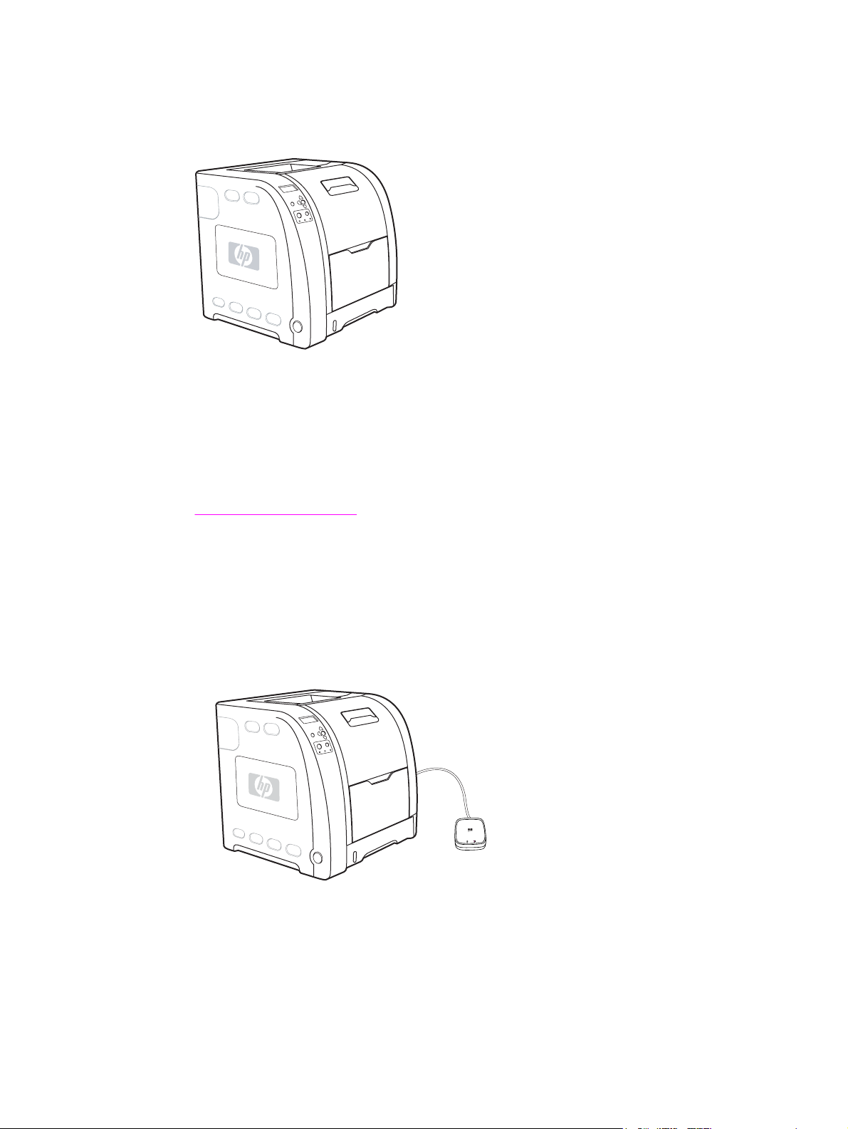
Printer configurations
HP Color LaserJet 3500/3550 printer
Figure 1-1.
HP Color LaserJet 3500/3550 printer
The HP Color LaserJet 3500 printer is a four-color laser printer that prints 12 pages per
minute (ppm) in both monochrome (black and white) and color. The HP Color LaserJet 3550
printer prints 16 pages per minute (ppm) in both monochrome (black and white) and color.
Trays. The printer comes with a multipurpose tray (Tray 1) that holds up to 100 sheets of
various paper types and sizes or 10 envelopes, and a 250-sheet paper feeder (Tray 2) that
supports various paper sizes. It supports an optional 500-sheet paper feeder (Tray 3). See
Print media specifications for more information.
Connectivity. The printer provides a high-speed Universal Serial Port (USB) 2.0 port for
connectivity.
Memory. The printer contains 64 megabytes (MB) of synchronous dynamic random access
memory (SDRAM).
HP Color LaserJet 3500n/3550n printer
Figure 1-2.
ENWW Printer configurations 3
HP Color LaserJet 3500n/3550n printer
The HP Color LaserJet 3500n/3550n printer includes the features of the HP Color LaserJet
3500/3550 printer, plus an HP Jetdirect en3700 external print server for easy connectivity to
10/100base-T networks.
Page 28
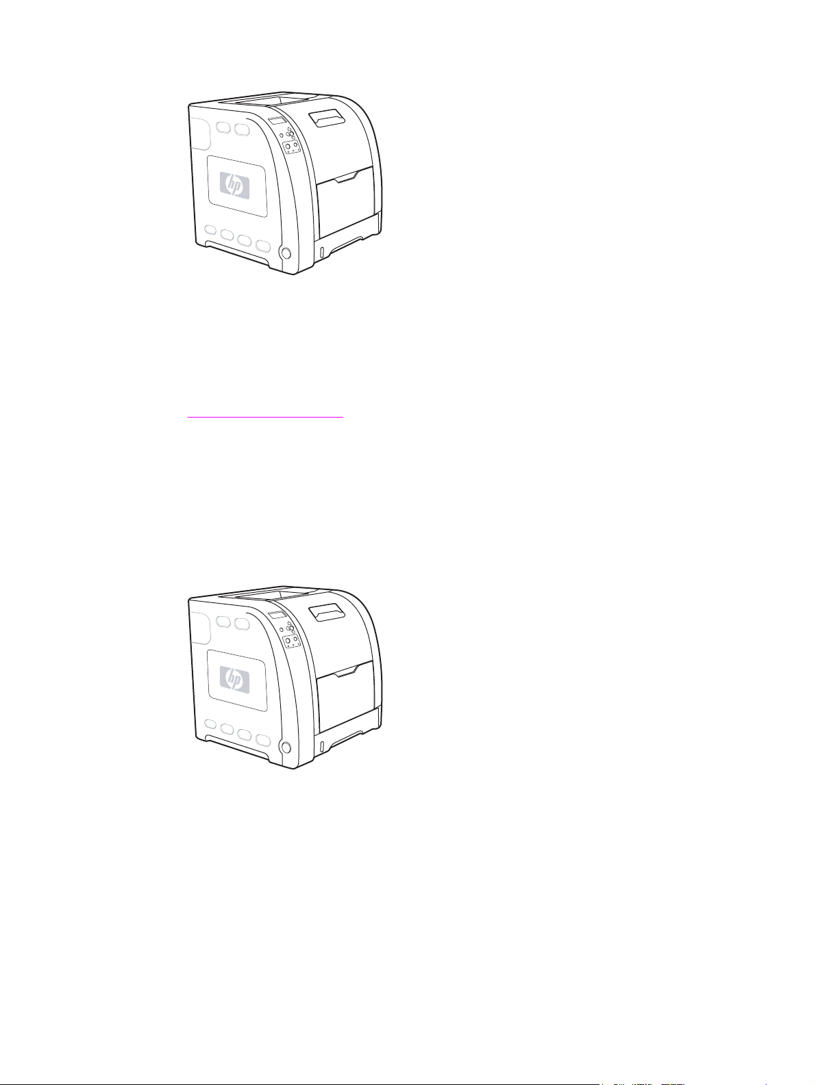
HP Color LaserJet 3700 printer
Figure 1-3.
HP Color LaserJet 3700 printer
The HP Color LaserJet 3700 printer is a four-color laser printer that prints 16 ppm in both
monochrome and color.
Trays. The printer comes with a multipurpose tray (Tray 1) that holds up to 100 sheets of
various paper types and sizes or 10 envelopes, and a 250-sheet paper feeder (Tray 2) that
supports various paper sizes. It supports an optional 500-sheet paper feeder (Tray 3). See
Print media specifications for more information.
Connectivity. The printer has a USB port and a standard bidirectional parallel port
(IEEE-1284 compliant) for connectivity.
Memory. The printer contains 64 MB of SDRAM. To allow for memory expansion, the printer
has three dual inline memory module (DIMM) slots that accept 64, 128, or 256 MB RAM
each. This printer can support up to 448 MB of memory.
HP Color LaserJet 3700n printer
Figure 1-4.
4 Chapter 1 Printer description ENWW
HP Color LaserJet 3700n printer
The HP Color LaserJet 3700n printer includes the features of the HP Color LaserJet 3700
printer, plus an HPJetdirect 615n print server for easy connectivity to 10/100 base-T networks.
Page 29
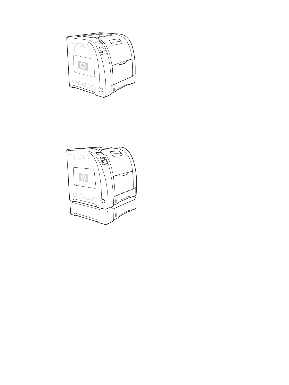
HP Color LaserJet 3700dn printer
Figure 1-5.
Figure 1-6.
HP Color LaserJet 3700dn printer
The HP Color LaserJet 3700dn printer includes the features of the HP Color LaserJet 3700n
printer, automatic two-sided (duplex) printing, and a total of 128 MB of SDRAM.
HP Color LaserJet 3700dtn printer
HP Color LaserJet 3700dtn printer
The HP Color LaserJet 3700dtn printer includes the features of the HP Color LaserJet
3700dn printer, with an additional 500-sheet paper feeder (Tray 3).
ENWW Printer configurations 5
Page 30
Printer features
Table 1-1. Features
Feature HP Color LaserJet 3500/3550
series printer
Performance ● 12 ppm (in both
monochrome and color). If
the performance of the
printer is less than this,
see the HP Color LaserJet
3550 and 3700 series
printer User Guide or
theHP Color LaserJet
3500 and 3700 series
printer User Guide for
factors affecting printer
performance.
● Prints on a variety of
media. For more
information see
media specifications.
Memory ● 64 MB of SDRAM. ● 64 MB of SDRAM.
User interface ● Graphic display on control
panel.
● Enhanced control panel
help.
● HP Toolbox (a web
application for status and
troubleshooting
information).
●
Windows
Macintosh print drivers.
Print
®
PC and Apple
HP Color LaserJet 3700
series printer
● 16 ppm (in both
monochrome and color). If
the performance of the
printer is less than this,
see the HP Color LaserJet
3550 and 3700 series
printer User Guide for
factors affecting printer
performance.
● Prints on a variety of
media. For more
information see
media specifications.
● MIPS RISC 350 MHz
processor.
● Can be expanded to 448
MB.
● Graphic display on control
panel.
● Enhanced control panel
help.
● HP Toolbox (a Web
application for status and
troubleshooting
information).
● Windows PC and Apple
Macintosh print drivers.
● Embedded Web server to
access support and order
supplies (administrator tool
for network-connected
printers).
Print
Supported printer personalities ● HP JetReady 4.1 for the
HP Color LaserJet
3500/3550 series printer.
Storage features ● Not applicable. ● Fonts and forms.
Environmental features ● PowerSave setting.
● High content of recyclable
components and materials.
● HP PCL 6.
● PostScript 3 emulation.
● Automatic language
switching.
● PowerSave setting.
● High content of recyclable
components and materials.
6 Chapter 1 Printer description ENWW
Page 31

Table 1-1. Features (continued)
Feature HP Color LaserJet 3500/3550
series printer
Fonts ● Not applicable. ● 80 internal fonts available
HP Color LaserJet 3700
series printer
for both PCL and
PostScript emulation.
Paper handling ● Prints on paper from 76 x
127 mm (3 x 5 inches) up
to 215 x 355 mm (8.5 x
14 inches).
● Prints on paper with
weights from 60 g/m2 to
163 g/m2 (16 to 43 lb bond).
● Prints on a wide range of
media types including
glossy, heavy, labels, film,
overhead transparencies,
and envelopes.
● Multiple gloss levels.
● A 250-sheet paper feeder
(Tray 2) that supports
letter, legal, executive,
executive (JIS), A4, A5, B5
(JIS), B5 (ISO), and 216 x
330 mm (8.5 x 13 inches)
paper sizes.
● Optional 500-sheet paper
feeder that supports letter
and A4 paper sizes
(Tray 3). For more
information see
Print
media specifications.
● A 150-sheet, face-down,
output bin (top) and a 25sheet, face-up, output bin
(rear).
● 80 printer-matching screen
fonts in TrueType
TM
format
available with the software
solution.
● Prints on paper from 76 x
127 mm (3 x 5 inches) up
to 215 x 355 mm (8.5 x
14 inches).
● Prints on paper with
weights from 60 g/m2 to
163 g/m2 (16 to 43 lb bond).
● Prints on a wide range of
media types including
glossy, heavy, labels, film,
overhead transparencies,
and envelopes.
● Multiple gloss levels.
● A 250-sheet paper feeder
(Tray 2) that supports
letter, legal, executive,
executive (JIS), A4, A5, B5
(JIS), B5 (ISO), and 216 x
330 mm (8.5 x 13 inches)
paper sizes.
● Optional 500-sheet paper
feeder that supports letter
and A4 paper sizes;
standard on the HP Color
LaserJet 3700dtn printer
(Tray 3). For more
information see
Print
media specifications.
● A 150-sheet, face-down,
output bin (top) and a 25sheet, face-up, output bin
(rear).
● Automatic two-sided
printing on HP Color
LaserJet 3700dn and
3700dtn printers.
Accessories ● Optional 500-sheet paper
feeder that supports letter
and A4 paper sizes
(Tray 3).
● Optional 500-sheet paper
feeder (Tray 3) that
supports letter and A4
paper sizes; standard on
the HP Color LaserJet
3700dtn printer (Tray 3).
● DIMM.
● Optional flash DIMM.
ENWW Printer features 7
Page 32

Table 1-1. Features (continued)
Feature HP Color LaserJet 3500/3550
series printer
HP Color LaserJet 3700
series printer
Connectivity ● High-speed universal
serial bus (USB) 2.0 cable
interface.
● HP Jetdirect en3700
external print server;
standard on theHP Color
LaserJet 3500n/3550n
printer.
● HP Web Jetadmin software.
Supplies ● Supplies status page
contains information on
toner level, page count,
and estimated pages
remaining.
● No-shake cartridge design.
● Printer checks for
authentic HP print
cartridges at cartridge
installation.
● Standard, bidirectional,
parallel cable interface
(IEEE-1284 compliant) for
backward compatibility.
● Universal serial bus (USB)
cable interface.
● Optional enhanced input/
output (EIO) network card;
standard on HP Color
LaserJet 3700n, 3700dn,
and 3700dtn printers.
● eP Embedded Web server.
● HP Web Jetadmin software.
● Supplies status page
contains information on
toner level, page count,
and estimated pages
remaining.
● No-shake cartridge design.
● Printer checks for
authentic HP print
cartridges at cartridge
installation.
● Internet-enabled supply
ordering capabilities (using
HP Toolbox).
● Internet-enabled supply
ordering capabilities (using
HP Toolbox).
8 Chapter 1 Printer description ENWW
Page 33

Printer assemblies
Front and rear features
The two figures below show the location of each major assembly in the printer. These
assemblies are described in the Installation and configuration chapter.
Figure 1-7.
Front view, HP Color LaserJet 3500/3550 and 3700 series printers (shown with
additional 500-sheet paper feeder)
1
On/off switch
2 Tray 3 (optional; 500 sheets of standard paper)
3 Tray 2 (250 sheets of standard paper)
4 Tray 1 (100 sheets of standard paper)
5 Front door
6 Printer control panel
7 Output bin extender (for use with all media types)
8 Output bin (150 sheets of standard paper)
9 DIMM access door (available on the HP Color LaserJet 3700 series printer)
ENWW Printer assemblies 9
Page 34

Figure 1-8.
Rear view, HP Color LaserJet 3500/3550 and 3700 series printers (shown with
additional 500-sheet paper feeder)
1 Upper rear door
2 Parallel connection (available on the HP Color LaserJet 3700 series printer)
3 Lower rear door (rear output bin) (25 sheets of standard paper)
4 USB connection
5 Power connection
6 Tray 3 (optional)
7 On/off switch
8 EIO connection (available on the HP Color LaserJet 3700 series printer)
9 DIMM access door (available on the HP Color LaserJet 3700 series printer)
10 Chapter 1 Printer description ENWW
Page 35

Site requirements
The printer must be kept in a proper location to maintain the performance level that has
been set at the factory. In particular, be sure that the environment adheres to the
specifications listed in this chapter.
Below are recommendations for the printer location and placement.
Make sure the printer has the following:
● a well-ventilated, dust-free area
● a hard, level surface (not more than a 2° angle) that can support approximately 43.4 kg
(95.5 lbs)
● a level surface that supports all four corners of the 500-sheet paper feeder
● constant temperature and humidity. (Do not install near water sources, humidifiers, air
conditioners, refrigerators, or other major appliances.)
Make sure to keep the printer away from the following:
● direct sunlight, dust, open flames, or water
●
direct flow of exhaust from air ventilation systems
● magnets and devices that emit a magnetic field
● areas subject to vibration
Figure 1-9.
● walls or other objects (There must be enough space around the printer for proper access
and ventilation. See the figures
LaserJet 3500/3550 series printer and Figure 1-10. Space requirements for the HP Color
LaserJet 3700 series printer with optional Tray 3, on the following pages.)
Figure 1-9. Space requirements for the HP Color
Space requirements
The printer must have the following amounts of space above and around it.
Space requirements for the HP Color LaserJet 3500/3550 series printer
1 Height: 722 mm (28.4 in.)
2 Depth: 1480 mm (58.3 in.)
3 Width: 699.5 mm (27.6 in.)
ENWW Site requirements 11
Page 36

Figure 1-10.
Space requirements for the HP Color LaserJet 3700 series printer with optional Tray 3
1 Height: 862 mm (34 in.)
2 Depth: 1480 mm (58.3 in.)
3 Width: 699.5 mm (27.6 in.)
Electrical specifications
WARNING!
Power requirements are based on the country/region where the printer is sold. Do not
convert operating voltages. This may damage the printer and void the product warranty.
Table 1-2. Electrical specifications lists the electrical specifications required to run the
printer safely and
Table 1-3. Power consumption for 110 and 220-volt (average in watts)1
lists the power consumption.
Table 1-2. Electrical specifications
Item 110-volt models 220-volt models
Power requirements 100 to 127 V (+/-10%) 50 to 60
Hz (+/- 2 Hz)
Minimum recommended circuit
capacity for typical product
5.3 A 3 A
Table 1-3. Power consumption for 110 and 220-volt (average in watts)
Product
HP Color
LaserJet
3500/3550
Printing
400 25 25 0.25 85
2
Ready
3
Power Save
220 to 240 V (+/-10%)
50 to 60 Hz (+/- 2 Hz)
1
4
Off Heat output-
Ready (BTU/
hour)
HP Color
LaserJet
3500n/3550n
400 26 26 0.25 89
12 Chapter 1 Printer description ENWW
Page 37

Table 1-3. Power consumption for 110 and 220-volt (average in watts)1 (continued)
Product
Printing
2
Ready
3
Power Save
4
Off Heat output-
Ready (BTU/
hour)
NOTE
HP Color
LaserJet 3700
HP Color
LaserJet
3700n
HP Color
LaserJet
3700dn
HP Color
LaserJet
3700dtn
1
The power consumptions reported are the highest values measured for color and
400 25 25 0.25 85
400 26 26 0.25 89
400 26 26 0.25 89
400 26 26 0.25 89
monochrome printing using standard voltages.
2
The printing speed is 16 ppm for letter-size media and 16 ppm for A4-size media.
3
The default activation time from Ready mode to PowerSave is 30 minutes.
4
The recovery time from PowerSave to the start of printing is 12 minutes.
These values are subject to change. For current information, see http://www.hp.com/support/
clj3500 for the HP Color LaserJet 3500 series printer, http://www.hp.com/support/clj3550 for
the HP Color LaserJet 3550 series printer, or http://www.hp.com/support/clj3700 for the
HP Color LaserJet 3700 series printer.
Environmental specifications
Keep the printer within the environmental conditions shown in Table 1-4. Environmental
specifications for optimum performance.
Table 1-4. Environmental specifications
Environment Recommended
Temperature 17° to 25°C (62.6° to 77°F) 10° to 27°C (50° to 81°F)
Humidity 20% to 60% RH 10% to 70% RH
Altitude Not applicable 0 to 2600 m (0 to 8530 ft)
Supply storage requirements
The life of supplies is greatly affected by their storage environment. Use Supply storage
requirements to determine the shelf life of stored supplies.
Table 1-5. Supply storage requirements
Item Storage time Storage condition
Allowed
Temperature Normal (maximum of 2.5 years) 0° to 35° C (32° to 95° F)
ENWW Site requirements 13
Page 38

Table 1-5. Supply storage requirements (continued)
Severe (maximum of 18 days)
Severe (maximum of 18 days)
High: 35° to 40° C (95° to 104°
F)
Low: 0° to -20° C (32° to -4° F)
Maximum temperature change
rate
40° to 15° C (104° to 59° F)
within 3 minutes
-20° to 25° C (-4° to 77° F)
within 3 minutes
Humidity Normal (maximum of 2.5 years) 35% to 85% RH
Severe (maximum of 18 days) High: 85% to 95% RH
Low: 10% to 35% RH
Atmospheric pressure 460 to 760 mm Hg (18.1 to
29.9 in Hg)
Storage time
1
The average storage time includes use time. Use cartridges within 2.5 years of the date
1
2.5 years
code on the cartridge.
14 Chapter 1 Printer description ENWW
Page 39

Printer specifications
Table 1-6. Physical dimensions
Product Height Depth Width Weight
HP Color
LaserJet
3500/3550 series
with print
cartridges
HP Color
LaserJet
3500/3550 series
printer with print
cartridges and
optional Tray 3
HP Color
LaserJet 3700
series printer with
print cartridges
HP Color
LaserJet 3700
series printer with
print cartridges
and optional
Tray 3
HP Jetdirect
en3700 external
print server
467 mm
(18.4 in)
603 mm
(23.8 in)
467 mm
(18.4 in)
603 mm
(23.8 in)
35 mm
(1.4 in)
447 mm
(17.6 in)
447 mm
(17.6 in)
447 mm
(17.6 in)
447 mm
(17.6 in)
131 mm
(5.2 in)
499.5 mm
(19.67 in)
499.5 mm
(19.67 in)
499.5 mm
(19.67 in)
499.5 mm
(19.67 in)
102 mm
(4 in)
36.6 kg
(80.52 lbs)
42 kg
(92.4 lbs)
37.8 kg
(83.16 lbs)
43.4 kg
(95.48 lbs)
0.159 kg
(0.35 lbs)
Table 1-7. Acoustic emissions
Activity level Operator (<1m) Bystander (1m) Sound power
NOTE
Active
Idle
Powersave
These values are subject to change. For current information, see http://www.hp.com/support/
L
64 dB (A) L
pAm
L
55 dB (A) L
pAm
L
N/A dB (A) L
pAm
49 dB (A) L
pAm
40 dB (A) L
pAm
N/A dB (A) L
pAm
6.4 Bels (A)
WAd
5.6 Bels (A)
WAd
N/A Bels (A)
WAd
clj3500 for the HP Color LaserJet 3500 series printer, http://www.hp.com/support/clj3550 for
the HP Color LaserJet 3550 series printer, or http://www.hp.com/support/clj3700 for the
HP Color LaserJet 3700 series printer.
Duty cycle
The HP Color LaserJet 3500 series printer maximum duty cycle is 45,000 pages per month.
Maximum duty cycle for the HP Color LaserJet 3550 series printer and HP Color LaserJet
3700 series printer is 55,000 pages per month.
ENWW Printer specifications 15
Page 40

Print media specifications
For optimum results, use conventional 75 g/m2 to 90 g/m2 (20 to 24 lb) photocopy paper.
Verify that the paper is of good quality and is free of cuts, nicks, tears, spots, loose particles,
dust, wrinkles, curls, or bent edges.
Supported media weights and sizes
Table 1-8. Tray 1 paper sizes1 shows the media types and sizes supported by the printer
and the printer accessories.
Table 1-8. Tray 1 paper sizes
1
Media Dimensions Weight or thickness Capacity
Minimum size paper 76 by 127 mm
(3 by 5 in)
Maximum size paper 216 by 356 mm
(8.5 by 14 in)
Minimum size glossy
paper
Maximum size glossy
paper
Minimum size
transparencies
2
Maximum size
transparencies
2
Minimum size
envelopes
Maximum size
envelopes
76 by 127 mm
(3 by 5 in)
216 by 356 mm
(8.5 by 14 in)
76 by 127 mm
(3 by 5 in)
216 by 356 mm
(8.5 by 14 in)
76 by 127 mm
(3 by 5 in)
216 by 356 mm
(8.5 by 14 in)
60 to 163 g/m
(16 to 43 lb bond)
60 to 163 g/m
(16 to 43 lb bond)
75 to 120 g/m
(20 to 32 lb bond)
75 to 120 g/m
(20 to 32 lb bond)
0.12 to 0.13 mm thick
(4.7 to 5 mils thick)
0.12 to 0.13 mm thick
(4.7 to 5 mils thick)
60 to 90 g/m
(16 to 24 lb bond)
60 to 90 g/m
(16 to 24 lb bond)
2
100 sheets
(75 g/m
2
100 sheets
(75 g/m
2
Maximum stack
height: 12 mm (0.47 in)
2
Maximum stack
height: 12 mm (0.47 in)
50 sheets
50 sheets
2
2
10 sheets
10 sheets
2
; 20 lb bond)
2
; 20 lb bond)
Minimum size label 76 by 127 mm
(3 by 5 in)
Maximum size label 216 by 356 mm
(8.5 by 14 in)
Minimum size
cardstock
Maximum size
cardstock
1
The printer supports a wide range of standard and custom sizes of print media. Capacity
76 by 127 mm
(3 by 5 in)
216 by 356 mm
(8.5 by 14 in)
75 to 163 g/m
(20 to 43 lb bond)
75 to 163 g/m
(20 to 43 lb bond)
135 to 216 g/m
(43 to 43 lb bond)
135 to 216 g/m
(43 to 43 lb bond)
2
2
2
2
50 sheets
50 sheets
50 sheets
50 sheets
can vary depending on media weight and thickness and environmental conditions.
Smoothness—100 to 250 (Sheffield).
2
Use only transparencies designed for use with HP Color LaserJet printers. This printer can
detect transparencies that were not designed for use with HP Color LaserJet printers.
The following table lists the standard sizes of paper that the printer supports in Tray 2.
16 Chapter 1 Printer description ENWW
Page 41

Table 1-9. Tray 2 paper sizes
1
Media Dimensions Weight or thickness Capacity
Letter 216 by 279 mm
(8.5 by 11 in)
Legal 216 by 356 mm
(8.5 by 14 in)
Executive 184 by 267 mm
(7.3 by 10.5 in)
Executive (JIS) 216 by 330 mm
(8.5 by 13 in)
A4 210 by 297 mm
(8.3 by 11.7 in)
A5 148 by 210 mm
(5.8 by 8.3 in)
B5 (JIS) 182 by 257 mm
(7.2 by 10.1 in)
B5 (ISO) 176 by 250 mm
(6.9 by 9.8 in)
1
Capacity can vary depending on media weight and thickness, and environmental conditions.
60 to 105 g/m
(16 to 28 lb bond)
60 to 105 g/m
(16 to 28 lb bond)
60 to 105 g/m
(16 to 28 lb bond)
60 to 105 g/m
(16 to 28 lb bond)
60 to 105 g/m
(16 to 28 lb bond)
60 to 105 g/m
(16 to 28 lb bond)
60 to 105 g/m
(16 to 28 lb bond)
60 to 105 g/m
(16 to 28 lb bond)
2
2
2
2
2
2
2
2
250 sheets
(75 g/m
2
; 20 lb bond)
250 sheets
(75 g/m
2
; 20 lb bond)
250 sheets
(75 g/m
2
; 20 lb bond)
250 sheets
(75 g/m
2
; 20 lb bond)
250 sheets
(75 g/m
2
; 20 lb bond)
250 sheets
2
(75 g/m
; 20 lb bond)
250 sheets
(75 g/m
2
; 20 lb bond)
250 sheets
(75 g/m
2
; 20 lb bond)
The following table lists the standard sizes of paper that the printer supports in Tray 3.
Table 1-10. Tray 3 paper sizes
1
Media Dimensions Weight or thickness Capacity
Letter 216 by 279 mm
(8.5 by 11 in)
A4 210 by 297 mm
(8.3 by 11.7 in)
1
Capacity can vary depending on media weight and thickness, and environmental conditions.
60 to 105 g/m
(16 to 28 lb bond)
60 to 105 g/m
(16 to 28 lb bond)
2
2
500 sheets
(75 g/m
2
; 20 lb bond)
500 sheets
(75 g/m
2
; 20 lb bond)
Table 1-11. Automatic two-sided printer (available on some models of the HP Color
LaserJet 3700 series printer)
Media Dimensions Weight or thickness Capacity
Letter 216 by 279 mm
Legal 216 by 356 mm
A4 210 by 297 mm
1
The printer automatically prints on paper weights up to 163 gm2 (43 lb bond). However,
1
(8.5 by 11 in)
(8.5 by 14 in)
(8.3 by 11.7 in)
60 to 105 g/m
2
(16 to 28 lb bond)
60 to 105 g/m
2
(16 to 28 lb bond)
60 to 105 g/m
2
(16 to 28 lb bond)
unlimited sheets sheets
unlimited sheets sheets
unlimited sheets sheets
automatic two-sided printing on weights above the maximum value noted in this table can
produce unexpected results.
ENWW Print media specifications 17
Page 42

Manual two-sided printing. Any of the supported paper sizes and types listed for printing
from Tray 1 can be manually duplexed. See the two-sided (duplex) printing section in the
HP Color LaserJet 3550 and 3700 series printer User Guide for more information.
18 Chapter 1 Printer description ENWW
Page 43

Hewlett-Packard warranty statement
HP PRODUCT
HP Color LaserJet 3500, 3500n, 3550, 3550n, 3700,
3700n, 3700dn, and 3700dtn printers
HP warrants to you, the end-user customer, that HP hardware and accessories will be free from defects in
materials and workmanship after the date of purchase, for the period specified above. If HP receives notice of
such defects during the warranty period, HP will, at its option, either repair or replace products which prove to be
defective. Replacement products may be either new or equivalent in performance to new.
HP warrants to you that HP software will not fail to execute its programming instructions after the date of
purchase, for the period specified above, due to defects in material and workmanship when properly installed and
used. If HP receives notice of such defects during the warranty period, HP will replace software which does not
execute its programming instructions due to such defects.
HP does not warrant that the operation of HP products will be uninterrupted or error free. If HP is unable, within a
reasonable time, to repair or replace any product to a condition as warranted, you will be entitled to a refund of
the purchase price upon prompt return of the product.
HP products may contain remanufactured parts equivalent to new in performance or may have been subject to
incidental use.
Warranty does not apply to defects resulting from (a) improper or inadequate maintenance or calibration, (b)
software, interfacing, parts or supplies not supplied by HP, (c) unauthorized modification or misuse, (d) operation
outside of the published environmental specifications for the product, or (e) improper site preparation or
maintenance.
TO THE EXTENT ALLOWED BY LOCAL LAW, THE ABOVE WARRANTIES ARE EXCLUSIVE AND NO OTHER
WARRANTY OR CONDITION, WHETHER WRITTEN OR ORAL, IS EXPRESSED OR IMPLIED AND
HP SPECIFICALLY DISCLAIMS ANY IMPLIED WARRANTIES OR CONDITIONS OF MERCHANTABILITY,
SATISFACTORY QUALITY, AND FITNESS FOR A PARTICULAR PURPOSE. Some countries/regions, states or
provinces do not allow limitations on the duration of an implied warranty, so the above limitation or exclusion
might not apply to you. This warranty gives you specific legal rights and you might also have other rights that vary
from country/region to country/region, state to state, or province to province. HP’s limited warranty is valid in any
country/region or locality where HP has a support presence for this product and where HP has marketed this
product. The level of warranty service you receive may vary according to local standards. HP will not alter form, fit
or function of the product to make it operate in a country/region for which it was never intended to function for
legal or regulatory reasons.
TO THE EXTENT ALLOWED BY LOCAL LAW, THE REMEDIES IN THIS WARRANTY STATEMENT ARE
YOUR SOLE AND EXCLUSIVE REMEDIES. EXCEPT AS INDICATED ABOVE, IN NO EVENT WILL HP OR ITS
SUPPLIERS BE LIABLE FOR LOSS OF DATA OR FOR DIRECT, SPECIAL, INCIDENTAL, CONSEQUENTIAL
(INCLUDING LOST PROFIT OR DATA), OR OTHER DAMAGE, WHETHER BASED IN CONTRACT, TORT, OR
OTHERWISE. Some countries/regions, states or provinces do not allow the exclusion or limitation of incidental or
consequential damages, so the above limitation or exclusion may not apply to you.
THE WARRANTY TERMS CONTAINED IN THIS STATEMENT, EXCEPT TO THE EXTENT LAWFULLY
PERMITTED, DO NOT EXCLUDE, RESTRICT OR MODIFY AND ARE IN ADDITION TO THE MANDATORY
STATUTORY RIGHTS APPLICABLE TO THE SALE OF THIS PRODUCT TO YOU.
DURATION OF LIMITED WARRANTY
One-year limited warranty
ENWW Hewlett-Packard warranty statement 19
Page 44

HP's Premium Protection Print Cartridge Warranty Limited Warranty Statement
This HP Print Cartridge is warranted to be free from defects in materials and workmanship.
This warranty does not apply to print cartridges that (a) have been refilled, refurbished,
remanufactured or tampered with in any way, (b) experience problems resulting from
misuse, improper storage, or operation outside of the published environmental specifications
for the printer product or (c) exhibit wear from ordinary use.
To obtain warranty service, please return the product to place of purchase (with a written
description of the problem and print samples) or contact HP customer support. At HP's
option, HP will either replace products that prove to be defective or refund your purchase
price.
TO THE EXTENT ALLOWED BY LOCAL LAW, THE ABOVE WARRANT Y IS EXCLUSIVE
AND NO OTHER WARRANTY OR CONDITION, WHETHER WRITTEN OR ORAL, IS
EXPRESSED OR IMPLIED AND HP SPECIFICALLY DISCLAIMS ANY IMPLIED
WARRANTIES OR CONDITIONS OF MERCHANTABILITY, SATISFACTORY QUALITY,
AND FITNESS FOR A PARTICULAR PURPOSE.
TO THE EXTENT ALLOWED BY LOCAL LAW, IN NO EVENT WILL HP OR ITS
SUPPLIERS BE LIABLE FOR DIRECT, SPECIAL, INCIDENTAL, CONSEQUENTIAL
(INCLUDING LOST PROFIT OR DATA), OR OTHER DAMAGE, WHETHER BASED IN
CONTRACT, TORT, OR OTHERWISE
THE WARRANTY TERMS CONTAINED IN THIS STATEMENT, EXCEPT TO THE EXTENT
LAWFULLY PERMITTED, DO NOT EXCLUDE, RESTRICT OR MODIFY AND ARE IN
ADDITION TO THE MANDATORY STATUTORY RIGHTS APPLICABLE TO THE SALE OF
THIS PRODUCT TO YOU.
20 Chapter 1 Printer description ENWW
Page 45

Premium Protection Warranty Color LaserJet Image Fuser Kit and
Image Transfer Kit Limited Warranty Statement
This HP product is warranted to be free from defects in materials and workmanship until the
printer provides a low-life indicator on the control panel.
This warranty does not apply to products that (a) have been refurbished, remanufactured or
tampered with in any way, (b) experience problems resulting from misuse, improper storage,
or operation outside of the published environmental specifications for the printer product or
(c) exhibit wear from ordinary use.
To obtain warranty service, please return the product to place of purchase (with a written
description of the problem) or contact HP customer support. At HP's option, HP will either
replace products that prove to be defective or refund your purchase price.
TO THE EXTENT ALLOWED BY LOCAL LAW, THE ABOVE WARRANTY IS EXCLUSIVE
AND NO OTHER WARRANTY OR CONDITION, WHETHER WRITTEN OR ORAL, IS
EXPRESSED OR IMPLIED AND HP SPECIFICALLY DISCLAIMS ANY IMPLIED
WARRANTIES OR CONDITIONS OF MERCHANTABILITY, SATISFACTORY QUALITY,
AND FITNESS FOR A PARTICULAR PURPOSE.
TO THE EXTENT ALLOWED BY LOCAL LAW, IN NO EVENT WILL HP OR ITS
SUPPLIERS BE LIABLE FOR DIRECT, SPECIAL, INCIDENTAL, CONSEQUENTIAL
(INCLUDING LOST PROFIT OR DATA), OR OTHER DAMAGE, WHETHER BASED IN
CONTRACT, TORT, OR OTHERWISE
THE WARRANTY TERMS CONTAINED IN THIS STATEMENT, EXCEPT TO THE EXTENT
LAWFULLY PERMITTED, DO NOT EXCLUDE, RESTRICT OR MODIFY AND ARE IN
ADDITION TO THE MANDATORY STATUTORY RIGHTS APPLICABLE TO THE SALE OF
THIS PRODUCT TO YOU.
ENWW
Premium Protection Warranty Color LaserJet Image Fuser Kit and Image Transfer Kit
Limited Warranty Statement 21
Page 46

Identification
HP's Product Stewardship program monitors product design to help protect the environment.
Model and serial numbers
The model number and serial numbers are listed on identification labels located on the rear
of the printer. The model number is alphanumeric, such as Q5990A for the HP Color
LaserJet 3550 printer. The serial number contains information about the country/region of
origin, the printer version, production code, and the production number of the printer (see
Figure 1-11. Serial number information).
Figure 1-11.
Serial number information
Table 1-12. Model names and numbers
Model name Model number
HP Color LaserJet 3500 Q1319A
HP Color LaserJet 3500n Q1320A
HP Color LaserJet 3550 Q5990A
HP Color LaserJet 3550n Q5991A
HP Color LaserJet 3700 Q1321A
HP Color LaserJet 3700n Q1322A
HP Color LaserJet 3700dn Q1323A
HP Color LaserJet 3700dtn Q1324A
Power and regulatory information
The identification label on the rear of the printer also contains power rating and regulatory
information as shown in
Figure 1-12. Sample label.
22 Chapter 1 Printer description ENWW
Page 47

CAUTION
Converting the voltage on the printer can damage the printer. Do not use any voltage other
than the operating voltage. Any attempt to convert operating voltages will void the product
warranty (for example, attempting to change a 110V printer to a 220V printer).
Figure 1-12.
Sample label
ENWW Identification 23
Page 48

Selecting paper
You can use many types of paper and other print media with this printer. This section
provides guidelines and specifications for selecting and using different print media.
Before purchasing any paper or specialized forms in quantity, verify that your paper supplier
obtains and understands the print media requirements specified in the HP LaserJet Printer
Family Print Media Specification Guide.
See the HP Color LaserJet 3550 and 3700 series printer User Guide or HP LaserJet Printer
Family Print Media Specification Guide for ordering information. To download a copy of the
HP LaserJet Printer Family Print Media Specification Guide go to http://www.hp.com/support/
clj3500 for the HP Color LaserJet 3500 series, to http://www.hp.com/support/clj3500 for the
HP Color LaserJet 3550 series and to http://www.hp.com/support/clj3700 for the HP Color
LaserJet 3700 series, and then select manuals.
It is possible that paper could meet all of the guidelines in this chapter or the HP LaserJet
Printer Family Print Media Specification Guide and still not print satisfactorily. This may be
due to abnormal characteristics of the printing environment or to other variables over which
Hewlett-Packard has no control (for example, extremes in temperature and humidity).
Hewlett-Packard recommends testing any paper before buying it in large quantities.
CAUTION
Using paper that does not conform to the specifications listed here or in the print media
guide can cause problems that require service. This service is not covered by the HewlettPackard warranty or service agreements.
Paper to avoid
The printer can handle many types of paper. Use of paper outside the printer specifications
will cause a loss of print quality and will increase the chance of paper jams.
● Do not use paper that is too rough.
●
Do not use paper with cutouts or perforations, other than standard 3-hole punched paper.
●
Do not use multipart forms.
● Do not use paper that has already been printed on, or that has been fed through a
photocopier.
● Do not use paper with a watermark if you are printing solid patterns.
Paper that can damage the printer
In rare circumstances, paper can damage the printer. The following paper must be avoided
to prevent possible damage to the printer:
● Do not use paper with staples attached.
● Do not use transparencies designed for Inkjet printers or other low-temperature printers,
or transparencies designed for monochrome printing. Use only transparencies that are
specified for use with HP Color LaserJet printers.
● Do not use photo paper intended for Inkjet printers.
24 Chapter 1 Printer description ENWW
Page 49

● Do not use paper that is embossed or coated, and that is not designed for the
temperatures of the HP Color LaserJet 3500/3550 and 3700 series printer image fusers.
Select paper that can tolerate temperatures of 190°C (374°F) for 0.1 second.
HP produces a selection of paper that is designed for the HP Color LaserJet 3500/3550
and 3700 series printer.
● Do not use letterhead paper with low-temperature dyes or thermography. Preprinted
forms or letterhead must use inks that can tolerate temperatures of 190°C (374°F) for
0.1 second.
● Do not use any media that produces hazardous emissions, or that melts, offsets, or
discolors when exposed to 190°C (374°F) for 0.1 second.
ENWW Selecting paper 25
Page 50

Printing on special media
Use these guidelines when printing on special types of media.
Transparencies
When printing on transparencies, use the following guidelines:
● Handle transparencies using the edges. Oils from your fingers deposited on the
transparency can cause print quality problems.
● Use only overhead transparencies recommended for use in this printer. Hewlett-Packard
recommends using HP Color LaserJet Transparencies with this printer. HP products are
designed to work together for optimum printing results.
● In either the software application or the printer driver, select TRANSPARENCY as the
media type, or print from a tray that is configured for transparencies.
CAUTION
NOTE
Transparencies not designed for LaserJet printing will melt in the printer, causing damage to
the printer. Do not use transparencies designed for monochrome printing.
Glossy paper
When printing on glossy paper, use the following guidelines:
● In either the software application or the driver, select Glossy as the media type, or print
from a tray that is configured for glossy paper.
2
Select Glossy for media weights up to 105 g/m
media weights up to 120 g/m
● Because these settings will affect all print jobs, it is important to return the printer to its
original settings once the job has printed.
Hewlett-Packard recommends using HP Color LaserJet Soft Gloss paper with this printer.
HP products are designed to work together for optimum printing results. If HP Color LaserJet
Soft Gloss paper is not used with this printer, print quality may be compromised.
2
(32 lb bond).
(28 lb bond). Select Heavy Glossy for
Colored paper
When printing on colored paper, use the following guidelines:
● Colored paper should be of the same high quality as white xerographic paper.
● Pigments used must be able to withstand the printer fusing temperature of 190°C (374°
F) for 0.1 second without deterioration.
● Do not use paper with a colored coating that was added after the paper was produced.
● The printer creates colors by printing patterns of dots, overlaying and varying their
spacing to produce various colors. Varying the shade or color of the paper will affect the
shades of the printed colors.
26 Chapter 1 Printer description ENWW
Page 51

Envelopes
NOTE
NOTE
Envelopes can be printed only from Tray 1. Set the tray media size to the specific envelope
size.
Adhere to the following guidelines to help ensure proper printing on envelopes and to help
prevent printer jams:
● Do not load more than ten envelopes into Tray 1.
●
The weight rating of envelopes should not exceed 90 g/m
● Envelopes should be flat.
● Do not use envelopes with windows or clasps.
● Envelopes must not be wrinkled, nicked, or otherwise damaged.
● Envelopes with peel-off adhesive strips must use adhesives that can withstand the heat
and pressures of the printer fusing process.
● Envelopes should be loaded face-down with the top of the envelope to the left, and the
short edge feeding into the printer first.
In high-humidity environments, envelopes should be printed long-edge first to prevent them
from sealing during printing. For long-edge printing, envelopes should be loaded long edge
first, face down. See the Printing envelopes from the Tray 1 section in the HP Color LaserJet
3550 and 3700 series printer User Guide to change the printer driver envelope orientation.
2
(24 lb bond).
NOTE
Labels
In either the application or the printer driver, selectLabels as the media type, or configure
Tray 1 for labels.
When printing labels, use the following guidelines:
● Verify that the label adhesive material can tolerate temperatures of 190°C (374°F) for
0.1 second.
● Verify that there is no exposed adhesive material between the labels. Exposed areas
can cause labels to peel off during printing, which can cause paper jams. Exposed
adhesive can also cause damage to printer components.
● Do not re-feed a sheet of labels.
● Verify that labels lie flat.
● Do not use labels that are wrinkled, bubbled, or otherwise damaged.
ENWW Printing on special media 27
Page 52

Heavy paper
When printing on heavy paper, use the following guidelines:
●
Any tray will print most heavy media that does not exceed 105 g/m
●
Use cardstock only in Tray 1 (135 g/m
●
In either the software application or the printer driver, select HEAVY (106 g/m
2
m
; 28 to 43 lb bond) or CARDSTOCK (135 g/m2 to 216 g/m2; 50 to 80 lb cover) as the
2
to 216 g/m2; 50 to 80 lb cover).
media type, or print from a tray that is configured for heavy paper. Because this setting
affects all print jobs, it is important to return the printer back to its original settings once
the job has printed.
2
(28 lb bond).
2
to 163 g/
CAUTION
In general, do not use paper that is heavier than the media specification recommended for
this printer. Doing so can cause misfeeds, paper jams, reduced print quality, and excessive
mechanical wear.
HP LaserJet Tough paper
When printing on HP LaserJet Tough paper, use the following guidelines:
● Handle HP LaserJet Tough paper only by the edges. Oils from your fingers deposited on
HP LaserJet Tough paper can cause print quality problems.
● Use only HP LaserJet Tough paper with this printer. HP products are designed to work
together for optimum printing results.
● In either the software application or the printer driver, select TOUGH PAPER as the
media type, or print from a tray that is configured for HP LaserJet Tough paper.
Preprinted forms and letterhead
When printing on preprinted forms and letterhead, use the following guidelines:
● Forms and letterhead must be printed with heat-resistant inks that will not melt, vaporize,
or release hazardous emissions when subjected to the printer fusing temperature of
approximately 190°C (374°F) for 0.1 second.
● Inks must be non-flammable and should not adversely affect any printer rollers.
● Forms and letterhead should be sealed in a moisture-proof wrapping to prevent changes
during storage.
● Before loading preprinted paper such as forms and letterhead, verify that the ink on the
paper is dry. During the fusing process, wet ink can come off preprinted paper.
● When duplex printing on the HP Color LaserJet 3700 series printer, load preprinted
forms and letterhead into Tray 2 and Tray 3 first side up, top edge toward the back of the
tray. To load preprinted forms and letterhead into Tray 1, load them with the first side
down, bottom edge in first.
● When simplex (one-sided) printing, load preprinted forms and letterhead into Tray 2 and
Tray 3 face-up with the top edge of the page to the left. To load preprinted forms and
letterhead into Tray 1, place them in the tray with the side to be printed facing up, and
top, short edge in first.
28 Chapter 1 Printer description ENWW
Page 53

Recycled paper
This printer supports the use of recycled paper. Recycled paper must meet the same
specifications as standard paper. See the HP LaserJet Printer Family Print Media
Specification Guide. Hewlett-Packard recommends that recycled paper contain no more than
five percent ground wood.
Media weight
Table 1-13. Weight equivalence table shows equivalent weights for different grades of
paper. A boldface type value indicates a commonly available standard weight for that grade.
NOTE
Text and book grades marked with an asterisk (*) actually calculate to 51, 61, 71, and 81 but
are rounded to standard book or text weights of 50, 60, 70, and 80.
Table 1-13. Weight equivalence table
Bond weight
(17 x 22 in.)
16# 41# 22# 27# 33# 37# 60 g/m2
17# 43# 24# 29# 35# 39# 64 g/m2
20# 50# * 28# 34# 42# 46# 75 g/m2
21# 54# 30# 36# 44# 49# 80 g/m2
24# 60# * 33# 41# 50# 55# 90 g/m2
27# 68# 37# 45# 55# 61# 100 g/m2
28# 70# * 39# 49# 58# 65# 105 g/m2
29# 74# 41# 50# 61# 68# 110 g/m2
Text/Book
weight
(25 x 38 in.)
Cover
weight (20
x 26 in.)
Bristol
weight
(22.5 x
28.5 in.)
Index weight
(25.5 x
30.5 in.)
Tag weight
(24 x 36 in.)
Metric
weight
32# 80# * 44# 55# 67# 74# 120 g/m2
36# 90# 50# 62# 75# 83# 135 g/m2
39# 100# 55# 67# 82# 91# 148 g/m2
40# 101# 55# 68# 83# 92# 150 g/m2
43# 110# 60# 74# 90# 100# 163 g/m2
45# 115# 63# 77# 94# 104# 170 g/m2
47# 119# 65# 80# 97# 108# 176 g/m2
51# 128# 70# 86# 105# 117# 190 g/m2
53# 134# 74# 90# 110# 122# 199 g/m2
54# 137# 75# 93# 113# 125# 203 g/m2
58# 146# 80# 98# 120# 133# 216 g/m2
ENWW Printing on special media 29
Page 54

Table 1-13. Weight equivalence table (continued)
65# 165# 90# 111# 135# 150# 244 g/m2
66# 169# 92# 114# 138# 154# 250 g/m2
67# 171# 94# 115# 140# 155# 253 g/m2
70# 178# 98# 120# 146# 162# 264 g/m2
72# 183# 100# 123# 150# 166# 271 g/m2
30 Chapter 1 Printer description ENWW
Page 55

Environmental product stewardship program
Environmental protection for this product is described in this section.
Protecting the environment
Hewlett-Packard Company is committed to providing quality products in an environmentally
sound manner. This product has been designed with several attributes to minimize impacts
on the environment.
Ozone production
This product generates no appreciable ozone gas (O3).
Power Consumption
Power usage drops significantly while in PowerSave mode, which saves natural resources
and saves money without affecting the high performance of this product. This product
qualifies for ENERGY STAR® (Version 3.0), which is a voluntary program to encourage the
development of energy-efficient office products.
NOTE
Paper use
ENERGY STAR® is a U.S. registered mark. As an ENERGY STAR partner, HewlettPackard Company has determined that this product meets ENERGY STAR Guidelines for
energy efficiency. For more information, see http://www.energystar.gov/.
Toner consumption
APPROVED mode uses significantly less toner, which might extend the life of the print
cartridge.
Paper use
This product’s optional, automatic, two-sided printing feature (duplex printing) can reduce
paper usage and the resulting demands on natural resources.
The HP Color LaserJet 3550, 3550n, 3700, and 3700n printers support the manual duplex
feature.
Plastics
Plastic parts over 25 grams are marked according to international standards that enhance
the ability to identify plastics for recycling purposes at the end of the product’s life.
ENWW Environmental product stewardship program 31
Page 56

HP LaserJet printing supplies
In many countries/regions, this product’s printing supplies (for example, print cartridges) can
be returned to HP through the HP Printing Supplies Returns and Recycling Program. An
easy-to-use and free takeback program is available in more than 30 countries/regions. Multilingual program information and instructions are included in every new HP LaserJetprint
cartridge and supplies package.
HP printing supplies returns and recycling program information
Since 1992, HP has offered HP LaserJet supplies return and recycling free of charge in 86%
of the world market where HP LaserJet supplies are sold. Postage-paid and pre-addressed
labels are included within the instruction guide in most HP LaserJet print cartridge boxes.
Labels and bulk boxes are also available through the Website: http://www.hp.com/recycle.
More than 10 million HP LaserJet print cartridges were recycled globally in 2002 through the
HP Planet Partners supplies recycling program. This record number represents 26 million
pounds of print cartridge materials diverted from landfills. Worldwide, HP recycled an
average of 80% of the print cartridge by weight consisting primarily of plastic and metals.
Plastics and metals are used to make new products such as HP products, plastic trays and
spools. The remaining materials are disposed of in an environmentally responsible manner.
● U.S. returns. For more environmentally responsible return of used cartridges and
supplies, HP encourages the use of bulk returns. Simply bundle two or more cartridges
together and use the single, pre-paid, and pre-addressed UPS label that is supplied in
the package. For more information in the U.S., call 1-800-340-2445 or visit the
HP Website at http://www.hp.com/recycle.
● Non-U.S. returns. Non-U.S. customers should visit the http://www.hp.com/recycle
Website for further information regarding availability of the HP Supplies Returns and
Recycling Program.
Paper
Material Safety Data Sheets (MSDS) for supplies containing chemical substances (for
example, toner) can be obtained by contacting the HP Website at http://www.hp.com/go/
msdshttp://www.hp.com/hpinfo/community/environment/productinfo/safety.
Material restrictions
This HP product does not contain batteries.
This HP product does not contain added mercury.
This product contains lead in solder that could require special handling at end-of-life.
For recycling information, see http://www.hp.com/recycle, contact your local authorities, or
go to the Electronics Industries Alliance Website http://www.eiae.org.
Material Safety Data Sheet (MSDS)
Material Safety Data Sheets (MSDS) for supplies containing chemical substances (for
example, toner) can be obtained by accessing the HP LaserJet Supplies Website at
http://www.hp.com/hpinfo/community/environment/productinfo/safety.htm.
32 Chapter 1 Printer description ENWW
Page 57

Extended warranty
HP SupportPack provides coverage for the HP hardware product and all HP-supplied
internal components. The hardware maintenance covers a three-year period from date of the
HP product purchase. The customer must purchase the HP SupportPack within 90 days of
the HP product purchase. For more information, contact the HP Customer Care Service and
HP Customer Support group. See
Hewlett-Packard warranty statement.
For more information
On HP environmental programs, including:
● Product environmental profile sheet for this and many related HP products
● HP’s commitment to the environment
● HP’s environmental management system
● HP’s end-of-life product return and recycling program
● Material Safety Data Sheets
See http://www.hp.com/go/environment or http://www.hp.com/hpinfo/community/environment/
productinfo/safety.
ENWW Environmental product stewardship program 33
Page 58

Declaration of Conformities
Declaration of Conformity
according to ISO/IEC Guide 22 and EN 45014
Manufacturer’s Name: Hewlett-Packard Company
Manufacturer's Address: 11311 Chinden Boulevard
Boise, Idaho 83714-1021, USA
declares, that the product
Product Name: HP Color LaserJet 3500
Regulatory Model Number:
Product Options: All
conforms to the following Product Specifications:
SAFETY: IEC 60950:1999 / EN60950: 2000
EMC :
Supplementary Information:
The product herewith complies with the requirements of the EMC Directive 89/336/EEC and the Low Voltage Directive 73/23/EEC, and carries
the CE-Marking accordingly.
1) The product was tested in a typical configuration with Hewlett-Packard Personal Computer Systems.
2) This Device complies with Part 15 of the FCC Rules. Operation is subject to the following two Conditions: (1) this device may not cause
harmful interference, and (2) this device must accept any interference received, including interference that may cause undesired operation.
3) For regulatory purposes, this product is assigned a Regulatory model number. This number should not be confused with the product names
or the product numbers.
For Regulatory Topics Only:
Australia Contact:
European Contact Your Local Hewlett-Packard Sales and Service Office or Hewlett-Packard Gmbh, Department HQ-TRE / Standards
USA Contact
3)
IEC 60825-1:1993 + A1:1997 +A2:2001 / EN 60825-1:1994 + A11:1996 +A2:2001 (Class 1 Laser/LED Product)
GB4943-2001
CISPR 22:1997 / EN 55022:1998 Class B
EN 61000-3-2:2000
EN 61000-3-3:1995\A1
EN 55024:1998
FCC Title 47 CFR, Part 15 Class B
GB9254-1998, GB17625.1-2003
Product Regulations Manager, Hewlett-Packard Australia Ltd., 31-41 Joseph Street, Blackburn, Victoria 3130, Australia
Europe, Herrenberger Straße 140, Böblingen, D-71034, Germany (FAX+49-7031-14-3143)
Product Regulations Manager, Hewlett-Packard Company, PO Box 15, Mail Stop 160, Boise, ID 83707-0015, USA
(Phone: 208-396-6000)
HP Color LaserJet 3550
BOISB-0302-01
1)
2)
/ ICES-003, Issue 4
Boise, Idaho 83713, USA
1 August 2004
34 Chapter 1 Printer description ENWW
Page 59

Declaration of Conformity
according to ISO/IEC Guide 22 and EN 45014
Manufacturer’s Name: Hewlett-Packard Company
Manufacturer's Address: 11311 Chinden Boulevard
Boise, Idaho 83714-1021, USA
declares, that the product
Product Name: HP Color LaserJet 3700/3700n/3700dn/3700dtn
Regulatory Model Number
4)
BOISB-0302-00
Including
Q2486A - Optional 500-Sheet Input Tray
Product Options: All
conforms to the following Product Specifications:
SAFETY: IEC 60950:1999 / EN60950: 2000
IEC 60825-1:1993 + A1:1997 +A2:2001 / EN 60825-1:1994 +A11:1996 + A2:2001 (Class 1 Laser/LED Product) /
GB4943-2001
EMC :
CISPR 22:1997 / EN 55022:1998 Class B
1), 3)
EN 61000-3-2:2000
EN 61000-3-3:1995\A1
EN 55024:1998
FCC Title 47 CFR, Part 15 Class B
2)
/ ICES-003, Issue 4/ GB9254-1998, GB17625.1-2003
Supplementary Information:
The product herewith complies with the requirements of the EMC Directive 89/336/EEC and the Low Voltage Directive 73/23/EEC, and carries
the CE-Marking accordingly.
1) The product was tested in a typical configuration with Hewlett-Packard Personal Computer Systems.
2) This Device complies with Part 15 of the FCC Rules. Operation is subject to the following two Conditions: (1) this device may not cause
harmful interference, and (2) this device must accept any interference received, including interference that may cause undesired operation.
3) The product includes LAN (Local Area Network) options. When the interface cable is attached to LAN connectors, the product meets the
requirements of EN55022 Class A, in which case the following applies: “Warning – This is a class A product. In a domestic environment this
product may cause radio interference in which case the user may be required to take adequate measures”.
4) For regulatory purposes, this product is assigned a Regulatory model number. This number should not be confused with the marketing
names (HP Color LaserJet 3700 series) or the product numbers (Q1321A, Q1322A, Q1323A, Q1324A).
Boise, Idaho 83713, USA
1 August 2004
For Regulatory Topics Only:
Australia Contact:
Product Regulations Manager, Hewlett-Packard Australia Ltd., 31-41 Joseph Street, Blackburn, Victoria 3130, Australia
European Contact Your Local Hewlett-Packard Sales and Service Office or Hewlett-Packard Gmbh, Department HQ-TRE / Standards
Europe, Herrenberger Straße 140, Böblingen, D-71034, Germany (FAX+49-7031-14-3143)
USA Contact
Product Regulations Manager, Hewlett-Packard Company, PO Box 15, Mail Stop 160, Boise, ID 83707-0015, USA
(Phone: 208-396-6000)
ENWW Declaration of Conformities 35
Page 60

Declaration of Conformity
according to ISO/IEC Guide 22 and EN 45014
Manufacturer’s Name: Hewlett-Packard Company
Manufacturer's Address: 8000 Foothills Blvd.
Roseville, California 95747-5677, USA
declares, that the product
Product Name: Jetdirect en3700 External print server
Regulatory Model Number
2)
RSVLD--0101
Model number, J7942A
conforms to the following Product Specifications:
SAFETY:
IEC 60950: 1999 3
rd
Edition / EN 60950: 2000
IEC 60825-1: 1993 +A1:1997 +A2:2001 / EN 60825-1: 1994 +A11:1996 +A2:2001 Class 1 (Laser/LED)
GB 4943: 1995
EMC :
EN 55022: 1998 Class B
1)
FCC Title 47 CFR, Part 15 Class B
ICES-003 Issue 4: 2004
EN 55024: 1998 +A1 2001 + A2: 2003
EN 61000-3-2: 2000
EN 61000-3-3 +A1: 2001
GB 9254: 1998
Supplementary Information:
1) The product herewith complies with the requirements of the Low Voltage Directive 73/23/EEC and the EMC Directive 89/336/EEC and
carries the CE marking accordingly.
2) For regulatory purposes this product is assigned a regulatory model number. This number should not be confused with the product name or
product number(s).
This product was tested in typical configurations with Hewlett-Packard Co. products.
Roseville, California 95747, USA
24 March 2004
For Regulatory Topics Only:
European Contact Your Local Hewlett-Packard Sales and Service Office or Hewlett-Packard Gmbh, Department HQ-TRE / Standards
Europe, Herrenberger Straße 140, Böblingen, D-71034, Germany (FAX+49-7031-14-3143)
USA Contact
Hewlett Packard Co. Corporate Product Regulations Manager, 3000 Hanover Street, Palo Alto, CA 94304, USA
(Phone 650-857-1501)
36 Chapter 1 Printer description ENWW
Page 61

Safety statements
Laser safety statement
The Center for Devices and Radiological Health (CDRH) of the U.S. Food and Drug
Administration has implemented regulations for laser products manufactured since
August 1, 1976. Compliance is mandatory for products marketed in the United States. The
printer is certified as a “Class 1” laser product under the U.S. Department of Health and
Human Services (DHHS) Radiation Performance Standard according to the Radiation
Control for Health and Safety Act of 1968. Since radiation emitted inside the printer is
completely confined within protective housings and external covers, the laser beam cannot
escape during any phase of normal user operation.
WARNING!
Using controls, making adjustments, or performing procedures other than those specified in
this service manual may result in exposure to hazardous radiation.
Canadian DOC regulations
Complies with Canadian EMC Class B requirements.
« Conforme ? la classe B des normes canadiennes de compatibilité électromagnétiques.
« CEM ». »
EMI statement (Korea)
Figure 1-13.
EMI statement for Korea
VCCI statement (Japan)
Figure 1-14.
ENWW Safety statements 37
VCCI statement for Japan
Page 62

Laser statement for Finland
Luokan 1 laserlaite
Klass 1 Laser Apparat
HP Color LaserJet 3550, 3550n, 3700, 3700n, 3700dn, 3700dtn, laserkirjoitin on käyttäjän
kannalta turvallinen luokan 1 laserlaite. Normaalissa käytössä kirjoittimen suojakotelointi
estää lasersäteen pääsyn laitteen ulkopuolelle. Laitteen turvallisuusluokka on määritetty
standardin EN 60825-1 (1994) mukaisesti.
VAROITUS !
Laitteen käyttäminen muulla kuin käyttöohjeessa mainitulla tavalla saattaa altistaa käyttäjän
turvallisuusluokan 1 ylittävälle näkymättömälle lasersäteilylle.
VARNING !
Om apparaten används p? annat sätt än i bruksanvisning specificerats, kan användaren
utsättas för osynlig laserstr?lning, som överskrider gränsen för laserklass 1.
HUOLTO
HP Color LaserJet 3500, 3500n, 3550, 3550n, 3700, 3700n, 3700dn, 3700dtn -kirjoittimen
sisällä ei ole käyttäjän huollettavissa olevia kohteita. Laitteen saa avata ja huoltaa
ainoastaan sen huoltamiseen koulutettu henkilö. Tällaiseksi huoltotoimenpiteeksi ei katsota
väriainekasetin vaihtamista, paperiradan puhdistusta tai muita käyttäjän käsikirjassa
lueteltuja, käyttäjän tehtäväksi tarkoitettuja ylläpitotoimia, jotka voidaan suorittaa ilman
erikoistyökaluja.
VARO !
Mikäli kirjoittimen suojakotelo avataan, olet alttiina näkymättömällelasersäteilylle laitteen
ollessa toiminnassa. Älä katso säteeseen.
VARNING !
Om laserprinterns skyddshölje öppnas d? apparaten är i funktion, utsättas användaren för
osynlig laserstr?lning. Betrakta ej str?len. Tiedot laitteessa käytettävän laserdiodin
säteilyominaisuuksista: Aallonpituus 775-795 nm Teho 5 m W Luokan 3B laser.
38 Chapter 1 Printer description ENWW
Page 63

FCC Regulations
This equipment has been tested and found to comply with the limits for a Class B digital
device, pursuant to Part 15 of the FCC rules. These limits are designed to provide
reasonable protection against harmful interference in a residential installation. This
equipment generates, uses, and can radiate radio frequency energy. If this equipment is not
installed and used in accordance with the instructions, it may cause harmful interference to
radio communications. However, there is no guarantee that interference will not occur in a
particular installation. If this equipment does cause harmful interference to radio or television
reception, which can be determined by turning the equipment off and on, the user is
encouraged to try to correct the interference by one or more of the following measures:
● Reorient or relocate the receiving antenna.
● Increase separation between equipment and receiver.
● Connect equipment to an outlet on a circuit different from that to which the receiver is
located.
● Consult your dealer or an experienced radio/TV technician.
NOTE
Any changes or modifications to the printer that are not expressly approved by HP could void
the user’s authority to operate this equipment.
Use of a shielded interface cable is required to comply with the Class B limits of Part 15 of
FCC rules.
ENWW FCC Regulations 39
Page 64

40 Chapter 1 Printer description ENWW
Page 65

Service approach
2
Chapter contents
This chapter contains the following sections.
Chapter contents .....................................................................................................................41
Search approach .....................................................................................................................42
Parts and supplies ...................................................................................................................43
Ordering parts ...................................................................................................................43
Ordering supplies ..............................................................................................................43
Exchange program ...........................................................................................................44
Supplies ............................................................................................................................44
World Wide Web ...............................................................................................................44
HP service parts information CD-ROM ............................................................................44
HP support assistant CD-ROM ........................................................................................44
Customer care reseller sales and service support center ................................................44
Ordering related documentation and software .................................................................45
HP maintenance agreements .................................................................................................46
On-site service agreements ..............................................................................................46
ENWW Chapter contents 41
Page 66

Search approach
Printer repair normally begins by using the printer internal diagnostics and the three-step
process below.
1. Isolate the problem to the major system (for example, the host computer, the network or
server, or the printer system).
2. Determine if the problem is located in an accessory or in the printer engine.
3. Troubleshoot the problem.
Once a faulty part is located, the printer can usually be repaired at the assembly level by
replacing field-replaceable units (FRUs). Some mechanical assemblies might need to be
repaired at the subassembly level. Hewlett-Packard does not support replacement of
components on the printer circuit assembles.
42 Chapter 2 Service approach ENWW
Page 67

Parts and supplies
This section identifies parts and supplies ordering information and how to obtain HP
assistance.
Ordering parts
Field-replaceable and accessory part numbers are found in chapter 8 of this manual. Order
replacement parts from Hewlett-Packard Customer Support-Americas (HPCS-A) or HewlettPackard Customer Support-Europe (HPCS-E).
NOTE
Use only accessories specifically designed for this printer. Accessories can be ordered from
an authorized service or support provider. See
later in this chapter and Ordering parts in chapter 8 for additional ordering information.
Ordering related documentation and software
By phone:
Hewlett-Packard Customer Support-Americas (HPCS-A) (800) 227-8164 (U.S. only)
Hewlett-Packard Customer Support-Europe (HPCS-E) (49) (70) 311 4225 (3)
By Internet:
Hewlett-Packard Parts Direct http://partsdirect.hp.com
By mail:
Hewlett-Packard Company
HPCS-A
8050 Foothills Blvd.
Roseville, CA 95678
Hewlett-Packard Company
HPCS-E
Wolf-Hirth Straße 33
D-7030 Böblingen, Germany
Ordering supplies
Order supplies directly from Hewlett-Packard. The phone numbers for ordering supplies are:
● U.S. HP Shopping (home) 1-888-999-4747
● U.S. Small/Medium Business store 1-800-888-0262
● Canada (800) 387-3154; Toronto (416) 671-8383
● United Kingdom (07) (34) 441 212
● Other local phone numbers may also be available
ENWW Parts and supplies 43
Page 68

Exchange program
HP offers remanufactured assemblies for some parts. These are identified in chapter 8 and
can be ordered from Hewlett-Packard Customer Support-Americas (HPCS-A) or HewlettPackard Customer Support-Europe (HPCS-E).
Supplies
Paper and print cartridges can be ordered directly from Hewlett-Packard. See chapter 8 for
ordering information.
World Wide Web
Printer drivers, updated HP printer software, and product and support information can be
obtained from the following website:
In the U.S.: http://www.hp.com/support/clj3500 or http://www.hp.com/support/clj3700
Printer drivers may be obtained from the following websites:
In China: http://www.hp.com.cn/support/clj3500 or ftp://www.hp.com.cn/support/clj3700
In Japan: ftp://www.jpn.hp.com/support/clj3500 or ftp://www.jpn.hp.com/support/clj3700
In Korea: http://www.hp.co.kr/support/clj3500 or http://www.hp.co.kr/support/clj3700
In Taiwan: http://www.hp.com.tw/support/clj3500 or http://www.hp.com.tw/support/clj3700 or
the local driver website: http://www.dds.com.tw
HP service parts information CD-ROM
This powerful, CD-ROM-based parts information tool is designed to give users fast, easy
access to parts information such as pricing and recommended stocking lists for a wide range
of HP products. To subscribe to this quarterly service in the U.S. or Canada, call
(800) 336-5987. In Asia Pacific, call (65) 740-4484. Parts identification and pricing
information can also be checked via the World Wide Web at http://www.hp.com/go/partsinfo.
HP support assistant CD-ROM
This support tool offers a comprehensive online information system designed to provide
technical and product information about HP products. To subscribe to the quarterly service in
the U.S. or Canada, call (800) 457-1762. In Hong Kong SAR, Indonesia, Malaysia, or
Singapore, call Mentor Media at (65) 740-4477.
Customer care reseller sales and service support center
The Customer Care Reseller Sales and Support Center is available to assist resellers and
service technicians. To reach this support center, call (1) (800) 544-9976.
HP authorized resellers and support
To locate authorized HP resellers and support, call (800) 243-9816 in the U.S. or (800)
387-3867 in Canada.
44 Chapter 2 Service approach ENWW
Page 69

HP service agreements
Call (800) 743-8305 in the U.S. or (800) 268-1221 in Canada.
Other areas
Outside of North America and Europe, contact the local HP sales office for assistance in
obtaining technical support for resellers and service technicians.
Ordering related documentation and software
Table 2-1. Related documentation and software shows where to order related
documentation and software. Telephone numbers for the various sources are:
● Hewlett-Packard Customer Support-Americas (HPCS-A) 1-800-hpinvent (U.S. only)
● Hewlett-Packard Customer Support-Europe (HPCS-E) (49) (70) 311 4225 (3)
Table 2-1. Related documentation and software
Description Part Number
HP LaserJet Family Print Media Guide 5851-1468
HP Color LaserJet 3500 Series Getting Started Guide Q1319-90901
HP Color LaserJet 3550 Series Getting Started Guide Q5990-90901
HP Color LaserJet 3700 Series Getting Started Guide Q1321-90925
HP Color LaserJet 3500 and 3700 Series Printer User Guide Q1321-90921
HP Color LaserJet 3550 and 3700 Series Printer User Guide Q5990-90910
HP Color LaserJet 3500/3700 Series Printer Service and Support
CD-ROM
HP Color LaserJet 3500/3700 Series Printer Service Training Kit Q1321-60117
Q1321-60115
ENWW Parts and supplies 45
Page 70

HP maintenance agreements
HP has several types of maintenance agreements that meet a wide range of support needs.
Maintenance agreements are not part of the standard warranty. Support services may vary
by area. Check with your local HP dealer to determine the services available to you.
On-site service agreements
To provide you with the level of support best suited to your needs, HP has on-site service
agreements with a selection of response times.
Next-day on-site service
This agreement provides support by the next working day following a service request.
Extended coverage hours and extended travel beyond HP’s designated service zones are
available on most on-site agreements (for additional charges).
Weekly (volume) on-site service
This agreement provides scheduled weekly on-site visits for organizations with many
HP products. This agreement is designated for sites using 25 or more workstation products,
including printers, plotters, computers, and disk drives.
Extended warranty
HP Carepak provides coverage for the HP hardware product and all HP-supplied internal
components. The hardware maintenance covers a one- to three-year period from date of the
HP product purchase. For more information, contact the HP Customer Care Service and
Support group.
46 Chapter 2 Service approach ENWW
Page 71

Installation and configuration
3
Chapter contents
This chapter contains the following sections:
Chapter contents .....................................................................................................................47
Checking the package contents ..............................................................................................48
Unpacking the printer ..............................................................................................................50
Installing the print cartridge .....................................................................................................55
Loading paper into Tray 3 (optional) .......................................................................................57
Loading paper into Tray 2 .......................................................................................................59
Loading paper into Tray 1 (optional procedure) ......................................................................61
Connecting power ...................................................................................................................62
Installing a new control panel overlay (optional) .....................................................................63
Testing the printer operation ...................................................................................................64
Using PowerSave Time ...........................................................................................................65
To set PowerSave Time ...................................................................................................65
To disable/enable PowerSave ..........................................................................................65
USB configuration ...................................................................................................................66
Connecting the USB cable ...............................................................................................66
Parallel configuration (HP Color LaserJet 3700 series printer only) .......................................67
Network configuration .............................................................................................................68
Enhanced I/O (EIO) configuration (HP color LaserJet 3700 series printer only) ....................69
HP Jetdirect print servers .................................................................................................69
Available enhanced I/O interfaces ....................................................................................69
NetWare networks ............................................................................................................70
Windows and Windows NT networks ...............................................................................70
AppleTalk networks ..........................................................................................................70
UNIX/Linux networks ........................................................................................................70
Printer software .......................................................................................................................71
Printer drivers ...................................................................................................................71
Software for networks .......................................................................................................72
Utilities ..............................................................................................................................73
Setting security on the printer .................................................................................................76
Locking the control panel ..................................................................................................76
Using an ASCII PJL escape sequence to set security .....................................................77
Printer memory for the HP Color LaserJet 3700 series printer ...............................................78
Installing memory and font DIMMs .........................................................................................79
Enabling memory ..............................................................................................................83
Enabling the language font DIMM (HP color LaserJet 3700 only) ...................................83
Checking DIMM installation (HP color LaserJet 3700 only) .............................................84
Installing an HP Jetdirect print server card in the HP color LaserJet 3700 series printer ......85
To install the HP Jetdirect print server card .....................................................................85
Installing an HP Jetdirect en3700 external print server ..........................................................88
ENWW Chapter contents 47
Page 72

Checking the package contents
Figure 3-1.
HP Color LaserJet 3500/3550 printer package contents
1 HP Color LaserJet 3500/3550
2 USB cable
3 Power cable
4 Four print cartridges
5 CD-ROM (the CD-ROM contains the user guide)
6 Control panel overlay
7 Getting started guide
Figure 3-2.
Additional contents shipped with the HP Color LaserJet 3500n/3550n printer
1 HP Jetdirect en3700 external print server (3500n/3550n only)
2 Power cable
48 Chapter 3 Installation and configuration ENWW
Page 73

NOTE
The items listed here are for the external print server connection.
Figure 3-3.
HP Color LaserJet 3700, 3700n, or 3700dn printer package contents
1 HP Color LaserJet 3700, 3700n, or 3700dn
2 Power cable
3 Four print cartridges
4 CD-ROM (the CD-ROM contains the user guide)
5 Control panel overlay
6 Getting started guide
Figure 3-4.
NOTE
HP Color LaserJet 3700dtn printer package contents
1 HP Color LaserJet 3700dtn
2 Tray 3 (500-sheet paper feeder tray)
3 Power cable
4 Four print cartridges
5 CD-ROM (the CD-ROM contains the user guide)
6 Control panel overlay
7 Getting started guide
Parallel and USB cables are not included with HP Color LaserJet 3700 series printers. Use
an IEEE 1284-compliant, parallel cable or a standard, 2-meter USB cable.
ENWW Checking the package contents 49
Page 74

Unpacking the printer
NOTE
WARNING!
CAUTION
Save all the packing materials in case you need to repack and transport the printer at a later
date.
The printer weighs approximately 33.5 kg (73.3 lbs). HP recommends having two or more
people lift or move the printer.
1. Prepare the location by selecting a sturdy, level surface in a well-ventilated, dust-free
area. Make sure there is enough space around the printer so that the air vents on the left
side and rear of the printer are not blocked.
Do not place the printer in direct sunlight or in an area that has abrupt temperature and
humidity changes.
NOTE
Recommended ranges: 17° to 25°C (62.6° to 77°F) and 20 to 60 percent relative humidity.
If the printer has an optional 500-sheet paper feeder, it is packaged on top of the printer. Lift
the 500-sheet paper feeder from the package, and place it in the prepared location.
50 Chapter 3 Installation and configuration ENWW
Page 75

2. Lift the printer from the packing pallet and place it in the prepared location. Two people
must lift and move the printer.
WARNING!
Do not lift the printer by the Tray 2 handle.
3. If you are using an optional 500-sheet paper feeder, lift the printer using the handles and
align the pegs on Tray 3. Lower the printer onto the tray.
NOTE
Only one Tray 3 (500-sheet input tray) can be installed.
ENWW Unpacking the printer 51
Page 76

4. Remove all external orange tape, orange protectors, and other packaging material.
5. Open Tray 2 and Tray 3 (if necessary), and remove the orange shipping lock inside each
tray.
52 Chapter 3 Installation and configuration ENWW
Page 77

6. Open the lower rear door, and make sure that the two blue pressure release lever
actuators are in the upright position. The two release levers are located on the left and
right side of the lower rear door.
7. Close the lower rear door.
8. Lift the front door handle, and pull down the front door.
NOTE
CAUTION
When you open the front door, you will hear components clicking.
Do not place anything on the transfer unit. Do not touch the top of the transfer unit or the
contacts on the left side of the transfer unit.
ENWW Unpacking the printer 53
Page 78

9. Remove the orange tape and orange shipping locks on the rear, left, and right sides of
the transfer unit. Remove any remaining tape from the printer.
54 Chapter 3 Installation and configuration ENWW
Page 79

Installing the print cartridge
1. Remove a new print cartridge from the bag.
2. Grasp both sides of the print cartridge and distribute the toner by gently rocking the
cartridge from side to side.
NOTE
3. Remove and discard the orange shipping tape and the shipping locks from the new print
cartridge.
Discard the shipping tape and the shipping locks according to local regulations.
ENWW Installing the print cartridge 55
Page 80

4. Locate the color slot for the print cartridge.
5. Align the print cartridge with the tracks inside the printer and, using the handle, insert the
cartridge. Repeat this procedure for the remaining three cartridges.
6. Firmly close the front door.
56 Chapter 3 Installation and configuration ENWW
Page 81

Loading paper into Tray 3 (optional)
1. Pull the tray out of the printer.
2. Adjust the length guides.
● Letter-size paper: Raise the blue rear stop.
● A4-size paper: Lower the blue rear stop.
3. Adjust the width guides.
● Letter-size paper: Press the center of the side width guides outward as far as
possible.
● A4-size paper: Press the blue ridges on the outside of the side width guides inward
as far as possible.
ENWW Loading paper into Tray 3 (optional) 57
Page 82

4. Load the paper into the tray. If this is special paper, such as letterhead, load it with the
side to be printed down and the top edge toward the front of the tray.
NOTE
Do not fan paper before loading.
5. Make sure the stack of paper is flat in the tray at all four corners, and keep it below the
height tabs.
6. Slide the tray back into the printer.
58 Chapter 3 Installation and configuration ENWW
Page 83

Loading paper into Tray 2
1. Pull Tray 2 out of the printer.
2. Move the side width guides until the blue arrows on the width guides point to the size of
paper you are loading.
3. On the back of the tray, press the blue ridges and slide the length guides until the arrow
symbol points to the paper size you are loading.
ENWW Loading paper into Tray 2 59
Page 84

4. Load the paper into the tray. If this is special paper, such as letterhead, load it with the
side to be printed down and the top edge toward the front of the tray.
NOTE
Do not fan the paper before loading.
5. Push down on the stack of paper to lock the metal lift plate into place. Make sure that
the stack of paper is flat and that the paper is below the height tabs.
6. Slide the tray back into the printer. Raise the output bin extension.
60 Chapter 3 Installation and configuration ENWW
Page 85

Loading paper into Tray 1 (optional procedure)
1. Open Tray 1, and raise the output bin extension.
NOTE
If printing special media, such as envelopes, use Tray 1.
2. Slide out the tray extender and, if necessary, open the additional tray extender.
3. Slide the width guides slightly wider than the print media. Remove any unused print
media, and close the tray when finished printing.
?
ENWW Loading paper into Tray 1 (optional procedure) 61
Page 86

Connecting power
1. Connect the AC power cord to the printer and to a power outlet.
NOTE
Do not connect the printer to the computer or to the network at this time.
2. Turn the printer on. After a minimum of two minutes, the green ready light turns on.
62 Chapter 3 Installation and configuration ENWW
Page 87

Installing a new control panel overlay (optional)
Overlays are available for several languages and come shipped with the printer. If you are
setting up a printer for a language other than English, complete the following procedure.
1. Select the language from the sheet of adhesive control panel overlays.
2. Position the new overlay over the top of the control panel. Set the overlay in place by
pressing down on the overlay and smoothing it across its surface.
ENWW Installing a new control panel overlay (optional) 63
Page 88

Testing the printer operation
Print a demo page to ensure the printer is working properly.
ENU
1. Press M
to enter the MENUS.
2. Press
3. Press
4. Press
5. Press
After printing the demo page, the printer control panel displays the Ready message.
to highlight Information.
to select Information.
to highlight PRINT DEMO.
to select PRINT CONFIGURATION.
64 Chapter 3 Installation and configuration ENWW
Page 89

Using PowerSave Time
The adjustable PowerSave Time feature reduces power consumption when the printer has
been inactive for an extended period. You can set the length of time before the printer goes
into PowerSave mode to 1 MINUTE, 15 MINUTES, 30 MINUTES, or to 1 HOUR, 1.5
HOURS, 2 HOURS, or 4 HOURS. The default setting is 30 MINUTES.
NOTE
The printer display appears dimmed when the printer is in PowerSave mode. PowerSave
mode does not affect printer warm-up time, unless the printer is in PowerSave mode for
more than eight hours.
To set PowerSave Time
1. Press M
2. Press
3. Press
4. Press
5. Press
6. Press
7. Press
8. Press
9. Press
10. Press M
ENU
to enter the MENUS.
to highlight Configure Device.
to select Configure Device.
to highlight SYSTEM SETUP.
to select SYSTEM SETUP.
to highlight Powersave Time.
to select Powersave Time.
or to select the appropriate time period.
to set the time period.
ENU
.
To disable/enable PowerSave
1. Press M
2. Press
3. Press
4. Press
5. Press
6. Press
7. Press
8. Press
9. Press
10. Press M
ENU
to enter the MENUS.
to highlight Configure Device.
to select Configure Device.
to highlight RESETS.
to select RESETS.
to highlight POWERSAVE.
to select POWERSAVE.
or to select on or off.
to set the selection.
ENU
.
ENWW Using PowerSave Time 65
Page 90

USB configuration
All printer models support USB connections. The USB port is on the back of the printer.
Connecting the USB cable
Plug the USB cable into the printer. Plug the other end of the USB cable into the computer.
Figure 3-5.
USB connection
1 USB port
2 USB connector
66 Chapter 3 Installation and configuration ENWW
Page 91

Parallel configuration (HP Color LaserJet 3700 series printer only)
TheHP Color LaserJet 3700 printer supports network and parallel connections at the same
time. A parallel connection is made by connecting the printer to the computer using a
bidirectional parallel cable (IEEE-1284 compliant) with a b-connector plugged into the printer
parallel port. The cable can be a maximum of 10 meters (or (30 feet)) long.
NOTE
Figure 3-6.
NOTE
When used to describe a parallel interface, the term bidirectional indicates that the printer is
able to both receive data from the computer and send data to the computer through the
parallel port. The parallel interface provides backwards compatibility; however, USB or
network connection is recommended to optimize performance.
Parallel port connection
1 B-connector
2 Parallel port
To use the enhanced capabilities of the bidirectional parallel interface, such as bidirectional
communication between the computer and printer, faster transfer of data, and automatic
configuration of printer drivers, ensure that the most recent printer driver is installed. For
more information, see
Printer software, later in this chapter.
NOTE
ENWW Parallel configuration (HP Color LaserJet 3700 series printer only) 67
Factory settings support automatic switching between the parallel port and one or more
network connections on the printer.
If the parallel cable is plugged in, the USB port is disabled.
Page 92

Network configuration
NOTE
NOTE
The network configuration feature is available for the HP Color LaserJet 3700 series printer
when an EIO device is installed.
You might need to configure certain network parameters on the printer. You can configure
these parameters from the printer control panel, the embedded Web server, or for most
networks, from the HP Web Jetadmin software or the HP Toolbox.
For more information about using the embedded Web server, see Using the embedded Web
server in the user guide.
For a complete list of supported networks and for instructions on configuring network
parameters from software, see the HP Jetdirect Print Server Administrator’s Guide. The
guide comes with printers in which an HP Jetdirect print server is installed.
68 Chapter 3 Installation and configuration ENWW
Page 93

Enhanced I/O (EIO) configuration (HP color LaserJet 3700 series printer only)
This printer comes equipped with one enhanced input/output (EIO) slot. This slot holds
compatible external devices, such as the HP Jetdirect print server network cards or other
devices.
EIO network cards can maximize printer performance when printing from a network. In
addition, they provide the ability to place the printer anywhere on a network. This eliminates
the need to attach the printer directly to a server or to a workstation, and allows you to place
the printer closer to the network users.
If the printer is configured through an EIO network card, configure that card through the
control panel Configure device menu.
HP Jetdirect print servers
An HP Jetdirect print server (network card) can be installed in the printer EIO slot. These
print server cards support multiple network protocols and operating systems. HP Jetdirect
print servers facilitate network management, allowing you to connect a printer directly to your
network at any location. HP Jetdirect print servers also support Simple Network
Management Protocol (SNMP), which provides network managers with remote printer
management and troubleshooting through HP Web Jetadmin software.
NOTE
NOTE
Installation of these cards and network configuration should be performed by a network
administrator. Configure the card either through the control panel, the printer installation
software, or with HP Web Jetadmin software.
See to the HP Jetdirect print server documentation for information on which external devices
or EIO network cards are supported.
Available enhanced I/O interfaces
HP Jetdirect print servers (network cards) provide software solutions for:
● Novell NetWare Network
● Microsoft Windows and Windows NT networks
● Apple Mac OS (AppleTalk)
● UNIX (HP-UX and Solaris)
● Linux (Red Hat and SuSE)
● Internet printing
For a summary of available network software solutions, see the HP Jetdirect Print Server
Administrator’s Guide, or visit HP Customer Care online at http://www.hp.com/support/
net_printing.
ENWW Enhanced I/O (EIO) configuration (HP color LaserJet 3700 series printer only) 69
Page 94

NetWare networks
When using Novell NetWare products with an HP Jetdirect print server, Queue Server mode
provides improved printing performance over Remote Printer mode. The HP Jetdirect print
server supports Novell Directory Services (NDS), as well as bindery modes. For more
information, see the HP Jetdirect Print Server Administrator’s Guide.
For Windows 98, Me, NT 4.0, 2000, and XP systems, use the printer installation utility for
printer setup on a NetWare network.
Windows and Windows NT networks
For Windows 98, Me, NT 4.0, 2000, and XP systems, use your printer installation utility for
printer setup on a Microsoft Windows network. The utility supports printer setup for either
peer-to-peer or client-server network operation.
AppleTalk networks
Use the HP Toolbox to set up the printer on an EtherTalk or LocalTalk network. For more
information, see the HP Jetdirect Print Server Administrator’s Guide included with printers
equipped with the HP Jetdirect print server.
UNIX/Linux networks
Use the HP Jetdirect printer installer for UNIX utility to set up the printer on HP-UX or Sun
Solaris networks.
For setup and management on UNIX or Linux networks, use HP Web Jetadmin.
To obtain HP software for UNIX/Linux networks, visit HP Customer Care online at
http://www.hp.com/support/net_printing. For other installation options supported by
theHP Jetdirect print server, see the HPJ etdirect Print Server Administrator’s Guide
included with printers equipped with the HP Jetdirect print server.
70 Chapter 3 Installation and configuration ENWW
Page 95

Printer software
Included with the printer is a CD-ROM containing the printing system software. The software
components and printer drivers on this CD-ROM help you use the printer to its fullest
potential. See the getting started guide for installation instructions.
NOTE
NOTE
For the latest information about the printing system software components, view the Readme
files on the CD-ROM.
This section summarizes the software included on the CD-ROM. The printing system
includes software for end users and network administrators operating in the following
operating environments:
● Microsoft Windows 98, Me, and NT 4.0
● Microsoft Windows 2000, XP 32-bit, and XP 64-bit
● Apple Mac OS version 9.1 and later, and Mac OS X version 10.1 and later
For a list of the network environments supported by the network administrator software
components, see
Network configuration.
For a list of printer drivers, updated HP printer software, and product support information for
the HP Color LaserJet 3500 series printer, go to http://www.hp.com/support/clj3500. For the
HP Color LaserJet 3550 series printer, go to http://www.hp.com/support/clj3550. For the
HP Color LaserJet 3700 series printer, go to http://www.hp.com/support/clj3700.
Printer drivers
Printer drivers access the printer features and allow the computer to communicate with the
printer. The following printer drivers are included with the printer on a CD-ROM.
Table 3-1. Printer drivers for the HP Color LaserJet 3500/3550 series printer
Operating system
Windows 98, Me
Windows NT 4.0
NOTE
Windows NT does not support USB.
Windows 2000
Windows XP (32-bit)
Windows XP (64-bit)
Windows Server 2003 (32-bit)
Windows Server 2003 (64-bit)
Macintosh OS
1
Not all printer features are available from all drivers or operating systems. See the online
1
JetReady 4.0
Help in your driver for availability of features.
ENWW Printer software 71
Page 96

Table 3-2. Printer drivers for the HP Color LaserJet 3700 series printer
Operating system
Windows 98, Me
Windows NT 4.0
NOTE
Windows NT does not support
USB.
Windows 2000
Windows XP (32-bit)
Windows XP (64-bit)
Windows Server 2003 (32-bit)
Windows Server 2003 (64-bit)
Macintosh OS
1
Not all printer features are available from all drivers or operating systems. See the online
1
2
2
23
PCL 6 PS Emulation
Help in your driver for availability of features.
2
For Windows 2000 and Windows XP (32-bit and 64-bit), download the PCL 5 driver from
http://www.hp.com/go/clj3700_software.
3
For Windows XP (64 bit), download the PCL 6 driver from http://www.hp.com/go/
clj3700_software.
NOTE
NOTE
NOTE
If your system did not automatically check the Internet for the latest drivers during software
installation, download them for the HP Color LaserJet 3500 series printer from
http://www.hp.com/go/clj3500_software. For the HP Color LaserJet 3550 series printer, go to
http://www.hp.com/go/clj3550_software. For the HP Color LaserJet 3700 series printer, go to
http://www.hp.com/go/clj3700_software.
Additional drivers
The following drivers are not included on the CD-ROM, but are available from
http://www.hp.com/go/clj3700_software. These drivers are for the HP Color LaserJet 3700
series printer only.
● OS/2 PS and PCL printer driver
● UNIX model scripts
● Linux drivers
The OS/2 drivers are available from IBM and are packaged with OS/2. They are not
available for Traditional Chinese, Simplified Chinese, Korean, and Japanese languages.
For more information about Windows 3.1x drivers, go to http://www.hp.com/support/clj3500
or http://www.hp.com/support/clj3700.
Software for networks
For a summary of available HP network installation and configuration software solutions, see
the HP Jetdirect Print Server Administrator’s Guide. You can find this guide on the CD
included with the printer.
72 Chapter 3 Installation and configuration ENWW
Page 97

HP Web Jetadmin
HP Web Jetadmin allows you to manage HP Jetdirect-connected printers within your intranet
using a browser. HP Web Jetadmin is a browser-based management tool and should be
installed only on the network administrator computer. It can be installed and run on a variety
of systems.
To download a current version of HP Web Jetadmin and, for the latest list of supported host
systems, visit HP Customer Care Online at http://www.hp.com/go/webjetadmin.
When installed on a host server, any client can access HP Web Jetadmin using a supported
Web browser (such as Microsoft Internet Explorer 4.x or Netscape Navigator 4.x or later) by
browsing to the HP Web Jetadminhost.
HP Web Jetadmin 6.5 and above have the following features:
● Task-oriented user interface provides configurable views, saving network managers
significant time.
● Customizable user profiles let network administrators include only the function viewed or
used.
● Instant e-mail notification of hardware failure, low supplies, and other printer problems
now route to different people.
● Remote installation and management from anywhere using only a standard Web browser.
● Advanced autodiscovery locates peripherals on the network, so the network
administrator does not need to manually enter each printer into a database.
● Simple integration into enterprise management packages.
● Quickly find peripherals based on parameters such as IP address, color capability, and
model name.
● Easily organize peripherals into logical groups, with virtual office maps for easy
navigation.
For the latest information about HP Web Jetadmin, go to http://www.hp.com/go/webjetadmin.
UNIX
The HP Jetdirect Printer Installer for UNIX is a simple printer installation utility for HP-UX and
Solaris networks. It is available for download from HP Customer Care Online at
http://www.hp.com/support/net_printing.
Linux
For information about Linux support, go to http://www.hp.com/go/linux.
Utilities
The HP Color LaserJet 3500/3550 series printer and the HP Color LaserJet 3700 series
printer are equipped with several utilities that make it easy to monitor and manage the printer
on a network.
ENWW Printer software 73
Page 98

HP Toolbox
The HP Toolbox is an application that you can use for the following tasks:
● Check the printer status.
● Configure the printer settings.
● View troubleshooting information.
● View online documentation.
● Print internal printer pages.
You can view the HP Toolbox when the printer is directly connected to your computer or
when it is connected to a network. You must have performed a complete software
installation to use the HP Toolbox.
Embedded Web server (available for the HP Color LaserJet 3700 series
printer)
This printer is equipped with an embedded Web server that allows access to information
about the printer and network activities. A Web server provides an environment in which
Web programs may run, much in the same way that an operating system, such as Windows,
provides an environment for programs to run on your PC. The output from these programs
can then be displayed by a Web browser, such as Microsoft Internet Explorer or Netscape
Navigator.
An embedded Web server resides on a hardware device (such as a printer) or in firmware,
rather than as software that is loaded on a network server.
The advantage of an embedded Web server is that it provides an interface to the printer that
anyone with a network-connected PC and a standard Web browser can access. There is no
special software to install or configure, but you must have a supported Web browser on your
computer. To access the embedded Web server, type the IP address for the printer in the
address line of the browser. (To find the IP address, print a configuration page. For more
information about printing a configuration page, see the user guide.)
Features
The HP embedded Web server allows you to view printer and network card status and
manage printing functions from your PC. With the HP embedded Web server, you can do the
following:
● View printer status information.
● Determine the remaining life on all supplies and order new ones.
● View and change tray configurations.
● View and change the printer control panel menu configuration.
● View and print internal pages.
● Receive notification of printer and supplies events.
● Add or customize links to other Web sites.
● Select the language in which to display the embedded Web server pages.
● View and change network configuration.
● View support content that is printer-specific and specific to the printer’s current state.
For a complete explanation of the features and functionality of the embedded Web server,
see the user guide.
74 Chapter 3 Installation and configuration ENWW
Page 99

Other components and utilities
Several software applications are available for Windows and Macintosh OS users, as well as
for network administrators. These programs are summarized below.
Table 3-3. Other software applications
Windows Macintosh OS Network administrator
● Software installer—
automates the printing
system installation
● Online Web registration
● HP toolbox—a Web
application for checking
printer status and settings
for Windows 98, 2000, Me,
and XP users
● PostScript Printer
Description files (PPDs)—
for use with the Apple
PostScript drivers that
come with the Mac OS
● HP Toolbox—a Web
application for checking
printer status and settings
for Mac OS X, v10.1, and
v10.2 users
● HP Web Jetadmin—a
browser-based system
management tool. See
http://www.hp.com/go/
webjetadmin for the latest
HP Web Jetadminsoftware
● HP Jetdirect Printer
Installer for UNIX—
available for download
from http://www.hp.com/
support/net_printing
ENWW Printer software 75
Page 100

Setting security on the printer
This printer features control panel locking, which allows network administrators to prevent
users from changing certain printer control panel settings. When a menu is locked,
unauthorized users trying to change settings in the printer control panel will receive the
following message:
Access Denied
MENUS LOCKED
You can use HP Web Jetadmin software, the HP LaserJet Utility for Macintosh, or an ASCII
escape sequence to perform this procedure. For instructions on locking the printer control
panel using either the HP Web Jetadmin software or the HP LaserJet Utility for Macintosh,
see the online Help for these utilities.
Locking the control panel
You can prevent users from changing printer control panel settings by establishing a
password and locking the printer control panel. You can choose from multiple levels of
security. You can lock certain control panel menus, allowing users to change the rest of the
menus, or you can lock all of the menus—and you can even lock the S
Levels of security
TOP
button.
Table 3-4. Printer security levels
Lock setting Control panel items locked
OFF Service menu (locked with factory set PIN)
LOW I/O submenu
System setup submenu
Resets submenu
Service menu (locked with factory-set PIN)
MEDIUM Configure Device menu (including all submenus)
Diagnostics menu
Service menu (locked with factory-set PIN)
HIGH Information menu
Paper Handling menu
Configure Device menu (including all submenus)
Diagnostics menu
Service menu (locked with factory-set PIN)
S
TOP
button
76 Chapter 3 Installation and configuration ENWW
 Loading...