

HP Engage One Retail System 143, Engage One Retail System 145, Engage One Retail System 141 Hardware Reference Manual
Page 1

Hardware Reference Guide
HP Engage One Retail System, Model 141
HP Engage One Retail System, Model 143
HP Engage One Retail System, Model 145
Page 2

© Copyright 2018 HP Development Company,
L.P.
ENERGY STAR® is a registered mark owned by
the U.S. government. Intel, Celeron, and Core
are trademarks of Intel Corporation in the
United States and/or other countries. Windows
is either a registered trademark or trademark
of Microsoft Corporation in the United States
and/or other countries.
The information contained herein is subject to
change without notice. The only warranties for
HP products and services are set forth in the
express warranty statements accompanying
such products and services. Nothing herein
should be construed as constituting an
additional warranty. HP shall not be liable for
technical or editorial errors or omissions
contained herein.
Third Edition: July 2018
First Edition: July 2017
Document Part Number: 925669-003
Product notice
This guide describes features that are common
to most models. Some features may not be
available on your computer.
Software terms
By installing, copying, downloading, or
otherwise using any software product
preinstalled on this computer, you agree to be
bound by the terms of the HP End User License
Agreement (EULA). If you do not accept these
license terms, your sole remedy is to return the
entire unused product (hardware and software)
within 14 days for a full refund subject to the
refund policy of your seller.
For any further information or to request a full
refund of the price of the computer, please
contact your seller.
Page 3

About This Guide
This guide provides basic information for upgrading this computer model.
WARNING! Indicates a hazardous situation that, if not avoided, could result in death or serious injury.
CAUTION: Indicates a hazardous situation that, if not avoided, could result in minor or moderate injury.
IMPORTANT: Indicates information considered important but not hazard-related (for example, messages
related to property damage). An Important alert warns the user that failure to follow a procedure exactly as
described could result in loss of data or in damage to hardware or software. Also contains essential
information to explain a concept or to complete a task.
NOTE: Contains additional information to emphasize or supplement important points of the main text.
TIP: Provides helpful hints for completing a task.
iii
Page 4

iv About This Guide
Page 5

Table of contents
1 Product overview .......................................................................................................................................... 1
Standard features .................................................................................................................................................. 1
Integrated features ................................................................................................................................................ 3
Stand options ......................................................................................................................................................... 4
HP Engage One Basic I/O Connectivity Base components .................................................................................... 4
HP Engage One Advanced I/O Connectivity Base components ............................................................................. 5
Connecting an AC adapter to power ...................................................................................................................... 6
Locating the Engage One power button ................................................................................................................ 7
Locating the I/O connectivity base power button ................................................................................................. 7
Adjusting the Engage One head unit ..................................................................................................................... 8
Engage One serial number location ...................................................................................................................... 9
I/O connectivity base serial number location ........................................................................................................ 9
2 Cable routing congurations ........................................................................................................................ 10
Cable matrix for Engage One with integrated column printer and basic I/O connectivity base ......................... 10
Cable matrix for Engage One with integrated column printer and advanced I/O connectivity base ................. 11
Cable matrix for Engage One without I/O connectivity base .............................................................................. 12
Cable matrix for Engage One with I/O connectivity base .................................................................................... 13
Cable matrix for Engage One with basic I/O connectivity base and standalone printer .................................... 14
Cable matrix for Engage One with advanced I/O connectivity base and standalone printer ............................. 15
3 Hardware congurations and upgrades ......................................................................................................... 16
Tools needed ........................................................................................................................................................ 16
Warnings and cautions ........................................................................................................................................ 16
Attaching an I/O connectivity base to the Engage One ....................................................................................... 17
Connecting a standalone I/O connectivity base to the Engage One ................................................................... 19
Conguring the I/O connectivity base’s powered serial ports ............................................................................ 19
Connecting a standalone optional ngerprint reader to the I/O connectivity base ........................................... 21
Attaching an optional ngerprint reader to the I/O connectivity base ............................................................... 22
Removing the Engage One head unit from the stand ......................................................................................... 24
Attaching the Engage One head unit to the stand .............................................................................................. 25
Mounting the Engage One head unit to a wall .................................................................................................... 25
Mounting the Engage One to a counter top ........................................................................................................ 27
Installing a security cable on the I/O connectivity base ..................................................................................... 29
Installing a security cable on the Engage One column ....................................................................................... 29
Installing a security screw on the Engage One head unit and stand .................................................................. 30
v
Page 6

Installing a security screw on the Engage One head unit and VESA mount ....................................................... 30
Removing the display panel ................................................................................................................................ 31
Replacing the display panel ................................................................................................................................. 32
System board components .................................................................................................................................. 34
Installing a 2 x 20 customer-facing display (CFD) ............................................................................................... 34
Installing memory ............................................................................................................................................... 37
DDR4-SDRAM SODIMMs .................................................................................................................... 37
Removing and installing a memory module ..................................................................................... 37
Removing and installing an M.2 solid-state drive (SSD) ..................................................................................... 40
Inserting an internal SD card ............................................................................................................................... 41
Removing and installing a WLAN module ........................................................................................................... 42
4 Using the column printer .............................................................................................................................. 44
Standard features ................................................................................................................................................ 44
Printing features .................................................................................................................................................. 44
When to change the receipt paper ...................................................................................................................... 45
Loading the printer receipt paper ........................................................................................................................ 45
Thermal paper specications .............................................................................................................................. 46
Qualied paper grades ........................................................................................................................................ 46
Troubleshooting the printer ................................................................................................................................ 47
Printer tone and green LED ............................................................................................................... 48
Printing issues ................................................................................................................................... 48
Printer does not function .................................................................................................................. 49
Latch failsafe ..................................................................................................................................... 50
Cleaning the printer ............................................................................................................................................. 50
5 Conguring the software .............................................................................................................................. 51
Touch screen calibration for Windows 10 Professional and Windows 10 IoT Enterprise for Retail .................. 51
Conguring optional HP integrated peripheral modules .................................................................................... 51
Appendix A Enabling encryption on the MSR ..................................................................................................... 52
Appendix B Electrostatic discharge .................................................................................................................. 53
Preventing electrostatic damage ........................................................................................................................ 53
Grounding methods ............................................................................................................................................. 53
Appendix C Computer operating guidelines, routine care, and shipping preparation ............................................ 54
Computer operating guidelines and routine care ............................................................................................... 54
Touch screen maintenance .................................................................................................................................. 54
MSR maintenance ................................................................................................................................................ 55
vi
Page 7

Shipping preparation ........................................................................................................................................... 55
Appendix D Accessibility ................................................................................................................................. 56
Supported assistive technologies ....................................................................................................................... 56
Contacting support .............................................................................................................................................. 56
Index ............................................................................................................................................................. 57
vii
Page 8

viii
Page 9
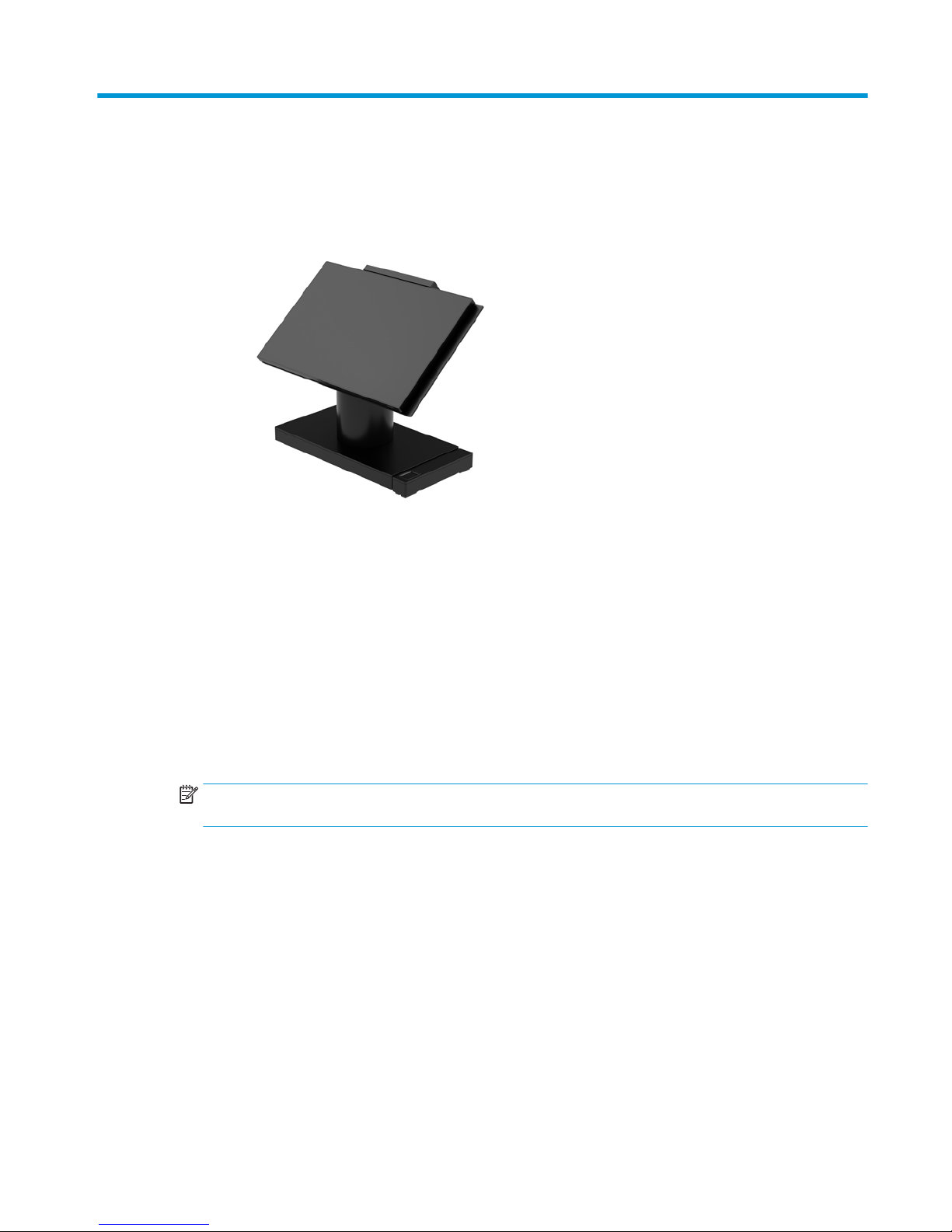
1 Product overview
Standard features
The HP Engage One Retail System is designed for long-term deployment within general retail, hospitality, and
other markets. It includes the following features:
● Integrated All-in-One (AiO) form factor
● 14-inch diagonal display panel (wide-aspect ratio); FHD 1920 x 1080 resolution, sealed and chemically
hardened, anti-glare; anti-smudge
● Model 141: anti-glare WLED SVA 300-nit panel with FHD 1920 x 1080 resolution and an Intel® Celeron®
3965U 2.2 GHz 2M 2133 2C6 processor
● Model 143: anti-glare WLED UWVA 500-nit panel with FHD 1920 x 1080 resolution and an Intel® Core™
i3 - 7100U 2.40 GHz 3M 2133 2C6 processor
● Model 145: anti-glare WLED UWVA 500-nit panel with FHD 1920 x 1080 resolution and an Intel® i5 -
7300U 2.60 GHZ 3MB 2133 2C6 processor
NOTE: Nits is the measure of the typical brightness of the panel as specied, prior to anti-glare
coating.
● Optional 100 mm x 100 mm VESA mounting bracket
● Optional counter top mounting bracket
● Choice of a rotate/tilt stand with a 10° tilt range and 180° swivel capability, or a xed position stand
● Optional HP peripherals:
– HP Engage One integrated magnetic strip reader (MSR) (integrated into the head unit as congure
to order)
– HP Engage One integrated 2 x 20 LCD customer-facing display (CFD), top mount
– HP Engage One integrated column printer or standalone printer
– HP Engage One 2D barcode scanner
– HP Engage One biometric ngerprint reader
Standard features 1
Page 10

● DDR4 2400 MHz memory with up to 32 GB RAM
● Operating system choices:
– Windows® 10 IoT Enterprise 2016 LTSB 64-bit
– Windows 10 Professional 64-bit
– FreeDOS 2.0
● HP Engage One Advanced I/O Connectivity Base (optional)
– 2 powered serial ports (0 V, 5 V, 12 V)
– (2) 12 V powered USB ports
– (1) 24 V powered USB port
– 4 USB 3.0 ports
– 1 cash drawer jack
– 1 RJ-45 network jack
– 1 video-out USB Type-C port
● HP Engage One Basic I/O Connectivity Base (optional)
– 3 powered serial ports (0 V, 5 V, 12 V)
– 4 USB 2.0 ports
– 2 USB 3.0 ports
– 1 cash drawer jack
– 1 RJ-45 network jack
– 1 video out USB Type-C port
● One internal SD card reader on the computer head unit and one external microSD card reader on the I/O
connectivity base
● Universal audio jack with CTIA headset support on the I/O connectivity base
● One M.2 SSD internal drive on the computer head unit
● ENERGY STAR® compliant
2 Chapter 1 Product overview
Page 11
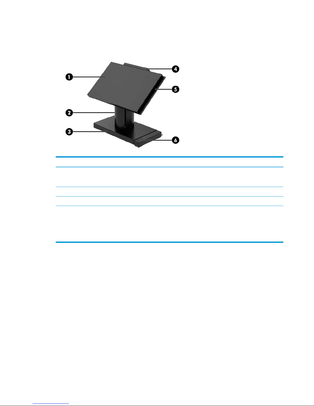
Integrated features
The integrated devices shown below are optional.
Features
(1) 14-inch diagonal display panel (wide-aspect ratio); FHD
1920 x 1080 resolution, sealed and chemically hardened,
anti-glare; anti-smudge
(4) HP Engage One 2 x 20 Customer-facing Display (CFD)
(2) HP Engage One Integrated Column Printer (5) HP Engage One Integrated MSR
(3) Choice of 2 Engage One I/O Connectivity Bases (6) HP Engage One Biometric Fingerprint Reader
Display panel options:
● Anti-glare WLED SVA 300 nits panel
● Anti-glare WLED UWVA 500 nits panel
NOTE: Nits is the measure of the typical brightness of the panel as specied, prior to anti-glare coating.
Integrated features 3
Page 12
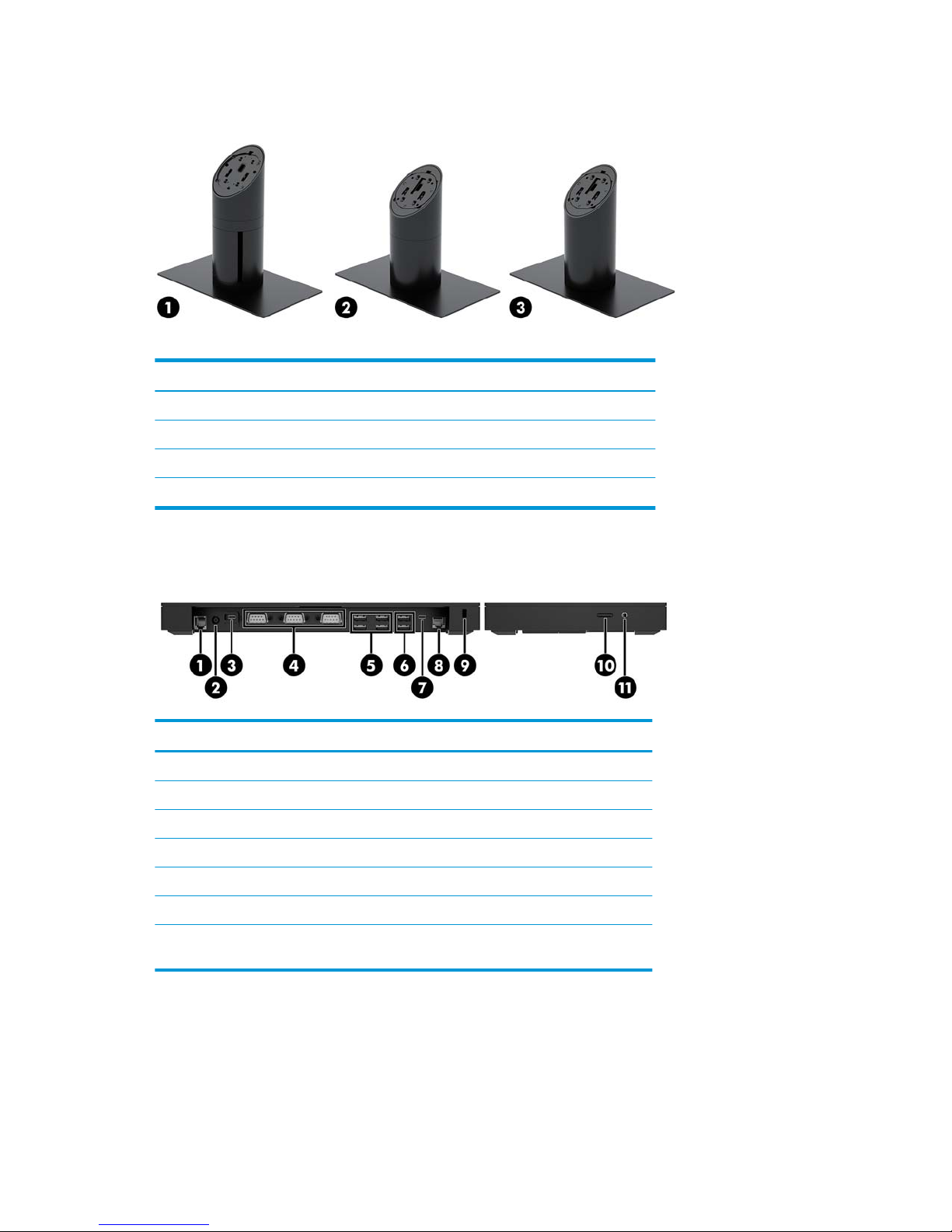
Stand options
Options
(1) HP Engage One Rotate/Tilt Stand with Integrated Column Printer
(2) HP Engage One Rotate/Tilt Stand
(3) HP Engage One Fixed Position Stand
NOTE: The stands are shown on a stability base.
HP Engage One Basic I/O Connectivity Base components
Basic components
(1) Cash drawer jack (7) USB Type-C port
(2) Power connector (8) RJ-45 network jack
(3) USB Type-C power port (9) Security cable slot
(4) Powered serial ports (3) (10) MicroSD card reader
(5) USB 2.0 ports (4) (11) Headset jack
(6) USB 3.0 ports (2)
IMPORTANT: To avoid damage to the computer, DO NOT plug a telephone cable into the cash
drawer jack.
4 Chapter 1 Product overview
Page 13

HP Engage One Advanced I/O Connectivity Base components
Advanced components
(1) Cash drawer jack (7) USB 3.0 ports (4)
(2) Powered USB 12 V ports (2) (8) USB Type-C port
(3) Powered USB 24 V port (9) RJ-45 network jack
(4) Power connector (10) Security cable slot
(5) USB Type-C power port (11) MicroSD card reader
(6) Powered serial ports (2) (12) Headset jack
IMPORTANT: To avoid damage to the computer, DO NOT plug a telephone cable into the cash
drawer jack.
HP Engage One Advanced I/O Connectivity Base components 5
Page 14
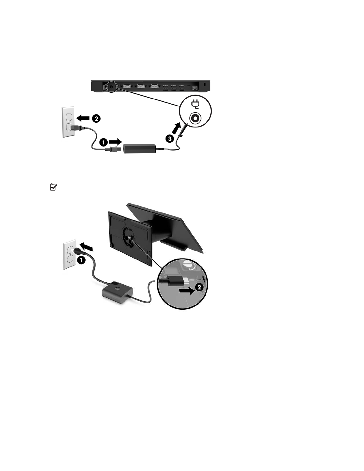
Connecting an AC adapter to power
To connect an AC adapter to the I/O connectivity base, connect one end of the power cord to the AC adapter (1)
and the other end to a grounded AC outlet (2), and then connect the AC adapter to the power connector on the
I/O connectivity base (3).
To connect an AC adapter to the computer when it is not connected to an I/O connectivity base, connect the AC
adapter to a grounded AC outlet (1), and then the connect the power adapter’s USB Type-C connector to the
USB Type-C power port on the underside of the stand or stability base (2).
NOTE: The image below is shown with a stability base.
6 Chapter 1 Product overview
Page 15
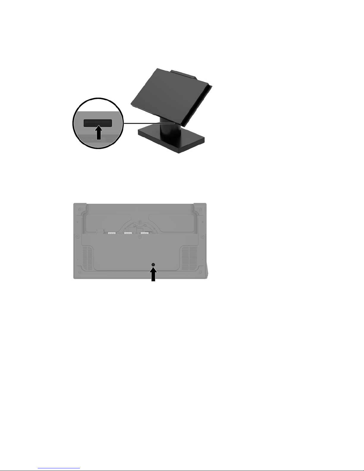
Locating the Engage One power button
The computer power button is located on the bottom right edge of the bezel.
Locating the I/O connectivity base power button
The I/O connectivity base power button is located on the underside of the I/O connectivity base.
The head unit controls the I/O connectivity base. When the head unit is turned o, the I/O connectivity base is
turned o and power is not available from the I/O connectivity base ports. The exception is the I/O
connectivity base’s USB Type-C port that connects to the head unit. That port will remain powered so that it
can continue to communicate with the head unit and allow the I/O connectivity base to turn back on when the
head unit is turned on.
After the system has been turned o, you can press the power button on the underside of the I/O connectivity
base to allow power to be available on the I/O connectivity base ports while the head unit remains turned o.
Locating the Engage One power button 7
Page 16
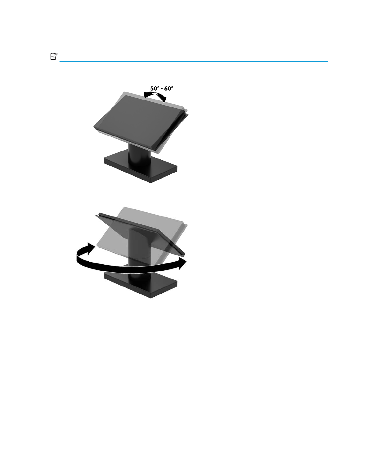
Adjusting the Engage One head unit
NOTE: The tilt and swivel features are only available on performance stands.
You can tilt and swivel the computer head to set it to a comfortable viewing angle. There is a 10° tilt range
that can be set between 50° and 60°.
The computer head unit can be swiveled 180° in either direction.
8 Chapter 1 Product overview
Page 17
Engage One serial number location
Each computer has a unique serial number and a product ID number that are located on the exterior of the
computer. Keep these numbers available for use when contacting customer service for assistance.
I/O connectivity base serial number location
Each I/O connectivity base has a unique serial number and a product ID number that are located on the
exterior of the I/O connectivity base. Keep these numbers available for use when contacting customer service
for assistance.
Regulatory information is located in the base plate or wall mount. Install the base plate or wall mount back
after disassembly.
Engage One serial number location 9
Page 18
2 Cable routing congurations
Cable matrix for Engage One with integrated column printer and
basic I/O connectivity base
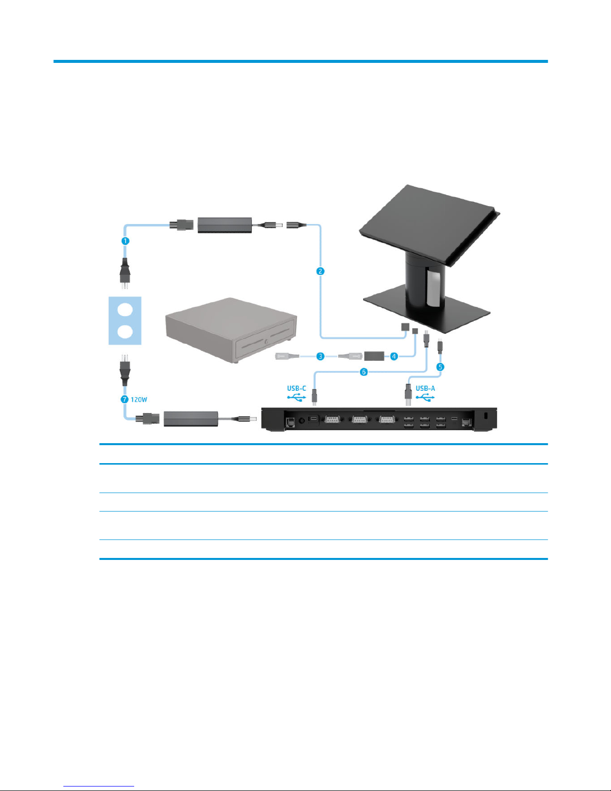
Cables
(1) Column printer AC power cord (5) I/O connectivity base mini USB Type-B to USB Type-A data
cable
(2) Column printer AC adapter cable (6) I/O connectivity base USB Type-C cable
(3) Cash drawer cable (purchased separately with cash
drawer)
(7) I/O connectivity base 120 W AC power cord
(4) Column printer cash drawer cable
10 Chapter 2 Cable routing congurations
Page 19
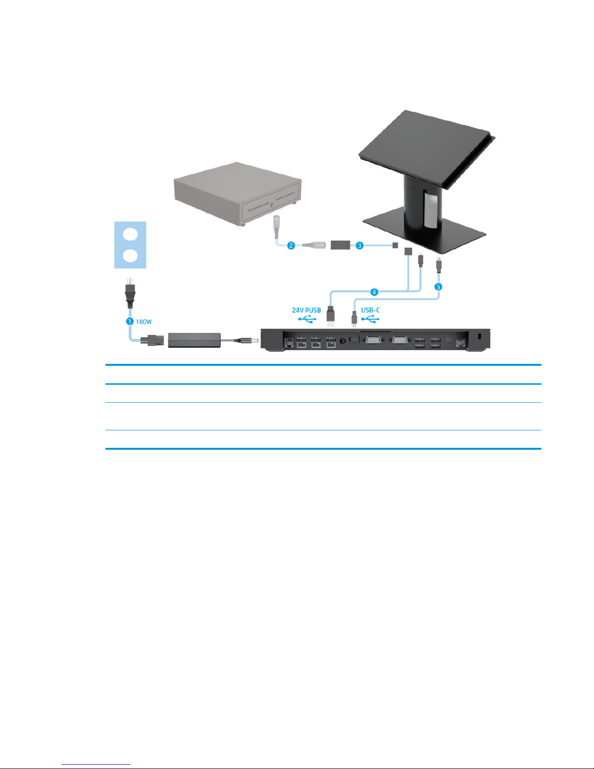
Cable matrix for Engage One with integrated column printer and
advanced I/O connectivity base
Cables
(1) I/O connectivity base 180 W AC power cord (4) Column printer 24 V PUSB power and data Y cable
(2) Cash drawer cable (purchased separately with cash
drawer)
(5) I/O connectivity base USB Type-C cable
(3) Column printer cash drawer cable
Cable matrix for Engage One with integrated column printer and advanced I/O connectivity base 11
Page 20
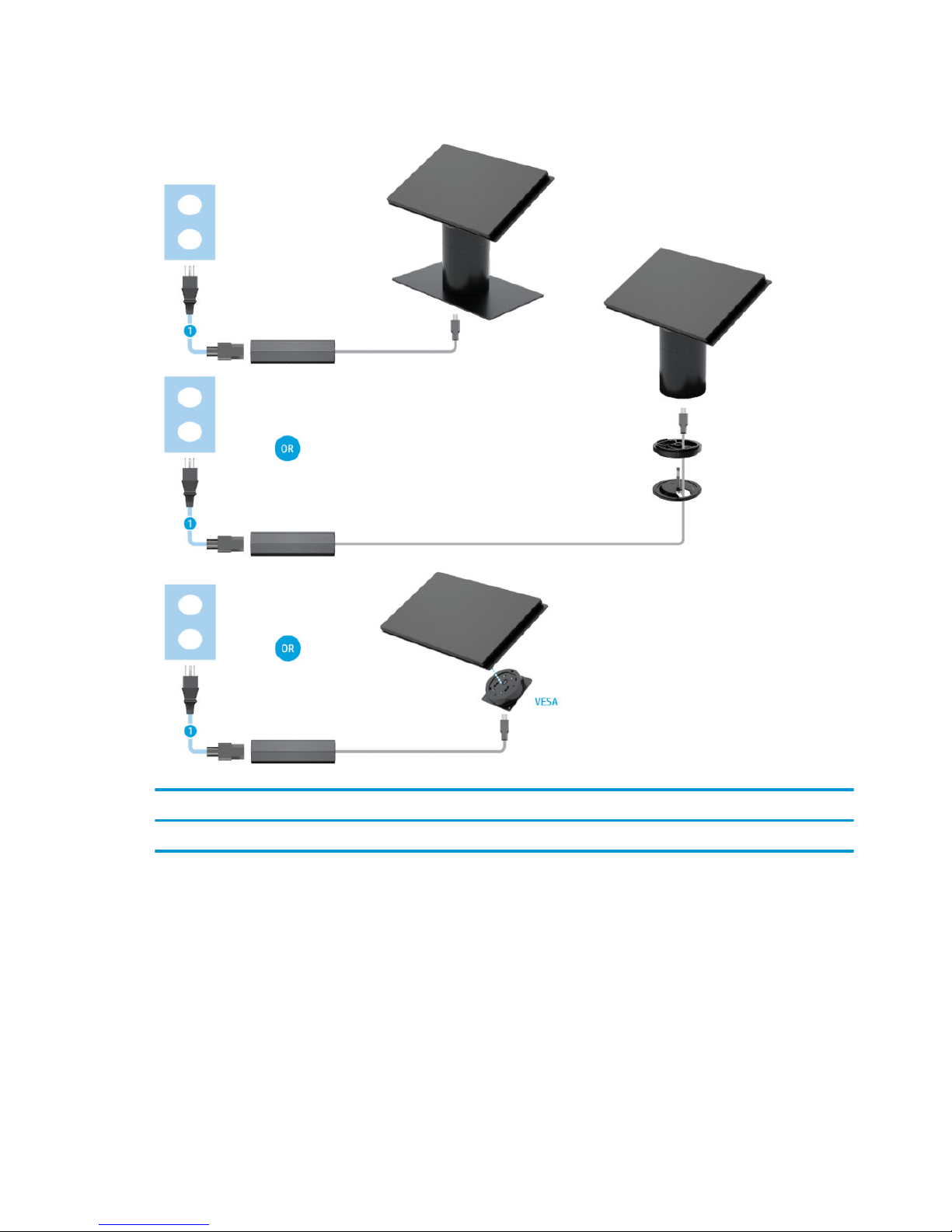
Cable matrix for Engage One without I/O connectivity base
Cables
(1) PC power cord
12 Chapter 2 Cable routing congurations
Page 21

Cable matrix for Engage One with I/O connectivity base
Cables
(1) Basic I/O connectivity base 120 W AC power cord (4) USB-C mini dock 90 W AC power cord
(2) I/O connectivity base USB Type-C cable (5) USB-C mini dock captive USB Type-C cable
(3) Advanced I/O connectivity base 180 W AC power cord
NOTE: In the European region, the USB-C mini dock is sold as an aftermarket option kit only. In all other
regions, the USB-C mini dock is sold as drop-in-box option.
Cable matrix for Engage One with I/O connectivity base 13
Page 22

Cable matrix for Engage One with basic I/O connectivity base
and standalone printer
Cables
(1) Printer AC power cord (4) Printer USB Type-A to Type-B data cable
(2) Basic I/O connectivity base 120 W AC power cord (5) Basic I/O connectivity base USB Type-C cable
(3) Printer serial data cable
IMPORTANT: Connect either the serial data cable (3) or the USB Type-A data cable (4) between the I/O connectivity base and the
printer. Do not connect both.
14 Chapter 2 Cable routing congurations
Page 23

Cable matrix for Engage One with advanced I/O connectivity
base and standalone printer
Cables
(1) Printer 24 V PUSB power and data “Y” cable (4) Printer serial data cable
(2) Advanced I/O connectivity base 180 W AC power adapter
cord
(5) Advanced I/O connectivity base USB Type-C cable
(3) Printer 24 V PUSB power cable
IMPORTANT: Connect either the 24 V PUSB power and data “Y” cable (1) or the 24 V PUSB power cable (3) and serial data cable (4)
between the I/O connectivity base and the printer. Do not connect all three.
Cable matrix for Engage One with advanced I/O connectivity base and standalone printer 15
Page 24

3 Hardware congurations and upgrades
Tools needed
A Phillips screwdriver can be used for procedures described in this guide.
Warnings and cautions
Before performing upgrades be sure to carefully read all of the applicable instructions, cautions, and
warnings in this guide.
WARNING! To reduce the risk of personal injury from electric shock, hot surfaces, or re:
Disconnect the power cord from the AC outlet before removing the enclosure. Energized parts are inside.
Allow the internal system components to cool before you touch them.
Replace and secure the enclosure before restoring power to the equipment.
Do not connect telecommunications or telephone connectors to the network interface controller (NIC)
receptacles.
Do not disable the power cord grounding plug. The grounding plug is an important safety feature.
Plug the power cord in a grounded (earthed) AC outlet that is easily accessible at all times.
For your safety, do not place anything on power cords or cables. Arrange them so that no one may
accidentally step on or trip over them. Do not pull on a cord or cable. When unplugging from the AC outlet,
grasp the cord by the plug.
To reduce the risk of serious injury, read the Safety & Comfort Guide. It describes proper workstation setup
and provides guidelines for posture and work habits that increase your comfort and decrease your risk of
injury. It also provides electrical and mechanical safety information. This guide is located on the web at
http://www.hp.com/ergo.
IMPORTANT: Static electricity can damage the electrical components of the computer or optional
equipment. Before beginning these procedures, ensure that you are discharged of static electricity by briey
touching a grounded metal object. See Electrostatic discharge on page 53 for more information.
When the computer is plugged into an AC power source, voltage is always applied to the system board. You
must disconnect the power cord from the power source before opening the computer to prevent damage to
internal components.
16 Chapter 3 Hardware congurations and upgrades
Page 25

Attaching an I/O connectivity base to the Engage One
You can attach an I/O connectivity base to the bottom of the computer’s stand.
1. Turn o the computer properly through the operating system, and turn o any external devices.
2. Disconnect the power cords from the computer and I/O connectivity base.
IMPORTANT: Regardless of the power-on state, voltage is always present on the system board as long
as the system is plugged into an active AC outlet. You must disconnect the power cord and wait
approximately 30 seconds for the power to drain to avoid damage to the internal components of the
computer.
3. Remove the cover on the I/O connectivity base by removing the four screws on the underside of the I/O
connectivity base (1), and then lifting the cover o the I/O connectivity base (2).
4. Connect the USB Type-C power cable to the USB Type-C port on the underside of the stand’s column.
Attaching an I/O connectivity base to the Engage One 17
Page 26

5. Place the I/O connectivity base onto the bottom of the stand (1), and then tighten the four screws on the
underside of the I/O connectivity base (2) to secure the I/O connectivity base to the stand. Be sure that
the USB Type-C power cable is routed through the gap between the back of the I/O connectivity base and
the stand.
6. To connect and secure the USB Type-C power cable, attach the cable clip to the cable (1), insert the cable
tie into the hole (2) below the USB Type-C port on the hub, and then slide the cable clip onto the cable tie
and connect the cable to the port (3).
7. Connect the I/O connectivity base’s AC adapter to the I/O connectivity base and a grounded AC outlet.
See Connecting an AC adapter to power on page 6.
18 Chapter 3 Hardware congurations and upgrades
Page 27

Connecting a standalone I/O connectivity base to the Engage
One
1. Turn o the computer properly through the operating system, and turn o any external devices.
2. Disconnect the power cords from the computer and I/O connectivity base.
IMPORTANT: Regardless of the power-on state, voltage is always present on the system board as long
as the system is plugged into an active AC outlet. You must disconnect the power cord and wait
approximately 30 seconds for the power to drain to avoid damage to the internal components of the
computer.
3. Connect the USB Type-C power cable to the USB Type-C port on the underside of the stand’s column and
to the USB Type-C power port on the I/O connectivity base.
4. Connect the I/O connectivity base’s power supply to the I/O connectivity base and a grounded AC outlet.
See Connecting an AC adapter to power on page 6.
Conguring the I/O connectivity base’s powered serial ports
The serial ports can be congured as standard (non-powered) serial ports or powered serial ports. Some
devices use a powered serial port. If the serial port is congured as a powered port, devices that support a
powered serial interface do not require an external power source.
IMPORTANT: The system must be powered o before connecting or disconnecting serial port devices.
NOTE: The I/O connectivity base ships with all serial ports congured in standard non-powered serial mode
(0 volts) by default.
There are three voltage settings for each serial port.
● 0 volts
● 5 volts
● 12 volts
To change the voltage settings for a powered serial port:
Connecting a standalone I/O connectivity base to the Engage One 19
Page 28

1. Turn o the computer properly through the operating system, and turn o any external devices.
2. Disconnect the power cord and all peripheral devices from the I/O connectivity base.
IMPORTANT: Regardless of the power-on state, voltage is always present on the system board as long
as the system is plugged into an active AC outlet. You must disconnect the power cord and wait
approximately 30 seconds for the power to drain to avoid damage to the internal components of the I/O
connectivity base.
3. Remove the ve screws on the underside of the I/O connectivity base (1) that secure the bottom plate to
the I/O connectivity base, and then remove the bottom plate from the I/O connectivity base (2).
4. Adjust the voltage select switch behind each serial port to the desired setting.
20 Chapter 3 Hardware congurations and upgrades
Page 29

5. Place the bottom plate onto the I/O connectivity base (1), and then secure the plate to the I/O
connectivity base with the ve screws (2).
6. Reconnect the I/O connectivity base’s power cord and peripheral devices.
Connecting a standalone optional ngerprint reader to the I/O
connectivity base
The optional ngerprint reader can be used as a standalone device or it can be attached to the I/O
connectivity base. Follow the procedure below to connect a standalone ngerprint reader to the I/O
connectivity base.
1. Turn o the computer properly through the operating system, and turn o any external devices.
2. Disconnect the power cords from the computer and I/O connectivity base.
IMPORTANT: Regardless of the power-on state, voltage is always present on the system board as long
as the system is plugged into an active AC outlet. You must disconnect the power cord and wait
approximately 30 seconds for the power to drain to avoid damage to the internal components of the
computer.
Connecting a standalone optional ngerprint reader to the I/O connectivity base 21
Page 30

3. Connect the USB cable to the ngerprint reader (1) and route the cable through the routing channel (2)
on the ngerprint reader.
4. Connect the ngerprint reader USB cable to a USB Type-A port on the I/O connectivity base.
5. Reconnect the I/O connectivity base and computer power cords.
Attaching an optional ngerprint reader to the I/O connectivity
base
The optional ngerprint reader can be used as a standalone device or it can be attached to the I/O
connectivity base. Follow the procedure below to attach the ngerprint reader to the I/O connectivity base.
NOTE: You can attach the ngerprint reader to either side of the I/O connectivity base, but if you attach it to
the left side of the I/O connectivity base, the ngerprint reader will cover the microSD slot and the headset
jack on the I/O connectivity base.
1. Turn o the computer properly through the operating system, and turn o any external devices.
2. Disconnect the power cords from the computer and I/O connectivity base.
IMPORTANT: Regardless of the power-on state, voltage is always present on the system board as long
as the system is plugged into an active AC outlet. You must disconnect the power cord and wait
approximately 30 seconds for the power to drain to avoid damage to the internal components of the
computer.
22 Chapter 3 Hardware congurations and upgrades
Page 31

3. Place the ngerprint reader (1) on the riser (2), and then attach the mounting bracket (3) and cable
routing clip (4) to the ngerprint reader and riser with the two long screws (5) included with the
ngerprint reader.
4. Connect the USB cable to the ngerprint reader (1) and route the cable under the routing clip on the
ngerprint reader (2). Remove the mounting screw (3) from the underside of the I/O connectivity base,
and then attach the bracket on the ngerprint reader assembly to the underside of the I/O connectivity
base (4) using the screw that was removed from the base and the short screw included in the kit.
Attaching an optional ngerprint reader to the I/O connectivity base 23
Page 32

5. Connect the ngerprint reader cable to a USB Type-A port on the I/O connectivity base.
6. Reconnect the I/O connectivity base and computer power cords.
Removing the Engage One head unit from the stand
1. Turn o the computer properly through the operating system, and turn o any external devices.
2. Disconnect the power cord from the computer.
IMPORTANT: Regardless of the power-on state, voltage is always present on the system board as long
as the system is plugged into an active AC outlet. You must disconnect the power cord and wait
approximately 30 seconds for the power to drain to avoid damage to the internal components of the
computer.
3. Insert a thin metal tool, such as a screwdriver, into the computer head unit release hole (1) on the stand
to depress the release button, and then pull the head unit from the stand (2).
NOTE: If a security screw is installed in the release hole, remove the screw with a T-10 screwdriver to
access the release button.
24 Chapter 3 Hardware congurations and upgrades
Page 33

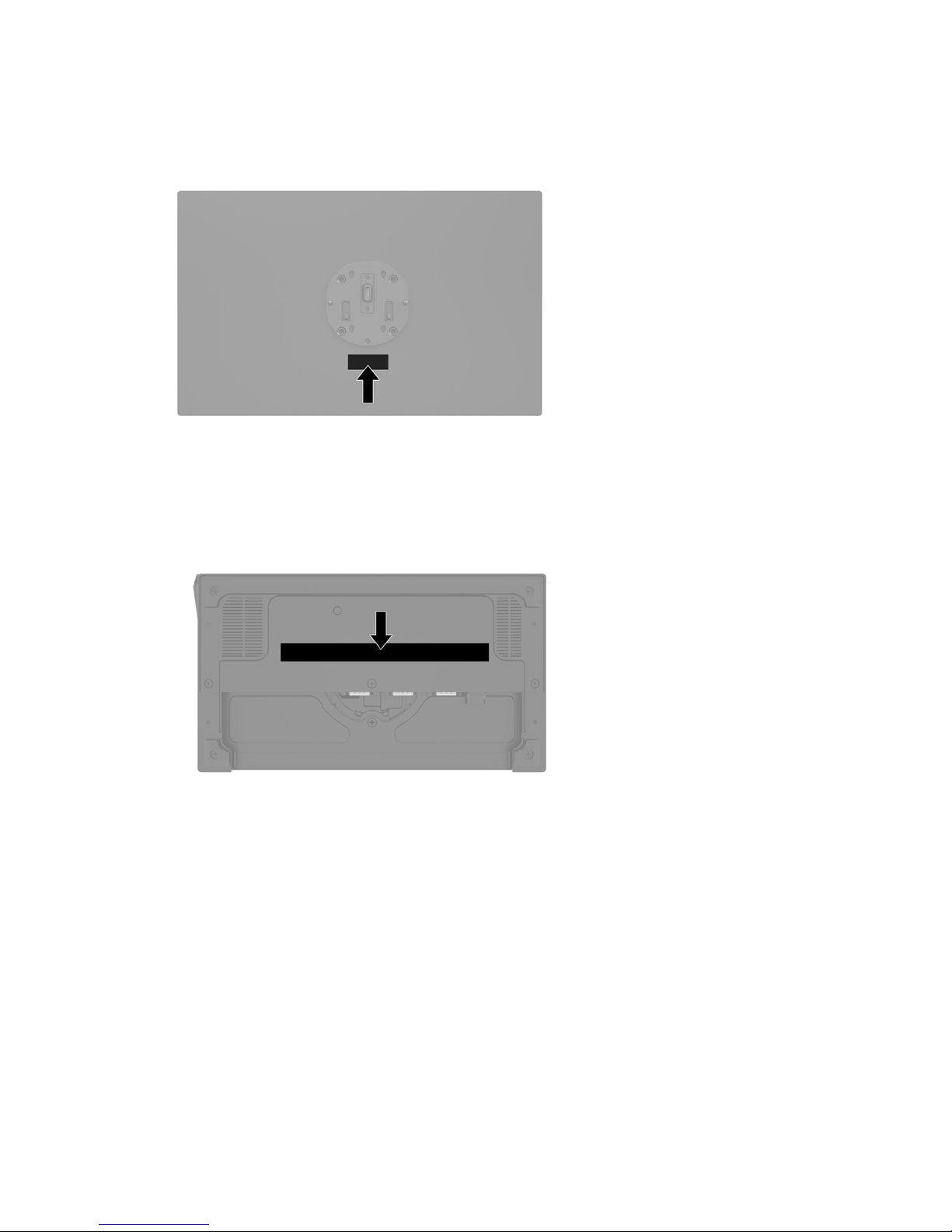
Attaching the Engage One head unit to the stand
1. Turn o the computer properly through the operating system, and turn o any external devices.
2. Disconnect the power cord from the computer.
IMPORTANT: Regardless of the power-on state, voltage is always present on the system board as long
as the system is plugged into an active AC outlet. You must disconnect the power cord and wait
approximately 30 seconds for the power to drain to avoid damage to the internal components of the
computer.
3. Align the guide posts on the rear of the computer head unit with the corresponding holes in the stand’s
column, and then press the head unit onto the column.
Mounting the Engage One head unit to a wall
You can use an optional VESA mounting bracket to mount the computer head unit to a wall.
1. If the computer head unit is attached to a stand, remove the head unit. See Removing the Engage One
head unit from the stand on page 24.
2. Attach the VESA mounting bracket to a wall.
3. Connect the USB Type-C power cable to the USB Type-C port on the VESA mounting bracket (1). Align the
guide posts on the rear of the computer head unit with the corresponding holes in the VESA mounting
bracket, and then press the head unit onto the VESA mounting bracket (2).
Attaching the Engage One head unit to the stand 25
Page 34

You also have the option of routing the USB Type-C cable out the rear of the VESA bracket and through a
wall instead of attaching a USB Type-C cable to the port on the side of the bracket.
a. Press the rear cover release tab (1) on the VESA bracket, and then pull the rear cover o the VESA
bracket (2). Unplug the cable from the inside of the VESA bracket.
b. Route the USB Type-C cable from the inside of the VESA bracket through the slot on the bracket’s
rear cover (1), and then replace the rear cover (2).
4. Connect the power cable from the VESA bracket to a wall outlet or I/O connectivity base.
26 Chapter 3 Hardware congurations and upgrades
Page 35

Mounting the Engage One to a counter top
You can use an optional counter top mounting bracket to mount the computer head unit and column to a
counter top.
NOTE: The mounting bracket requires an 80 mm hole in the counter top. The thickness of the counter top
must be 10 mm to 50 mm.
1. If the stand’s base is attached to the column, remove the screw on the underside of the column (1), and
then remove the base from the column (2).
2. Route the cable(s) through the routing hole on the top piece of the mounting bracket (1) and attach the
cable(s) to the bottom of the column (2).
NOTE: If the column has a printer, there are four cables to connect. If it does not have a printer, there is
one cable to connect.
Mounting the Engage One to a counter top 27
Page 36

3. Hold the top piece of the mounting bracket against the bottom of the column, route the cables through
the hole in the mounting surface, and then place the column over the hole on the mounting surface.
4. The bottom piece of the mounting bracket can be oriented in two ways, depending on the thickness of
your mounting surface. Orient the bracket properly for your application before attaching it.
5. Route the cables through the hole in the bottom piece of the mounting bracket (1). Press the mounting
bracket against the bottom of the mounting surface (2), and then insert the screw (3) though the
mounting bracket. Then tighten the screw (4) so that the screw is fully inserted into the column, and
then tighten the wing nut (5) on the screw to fasten the bracket to the mounting surface.
28 Chapter 3 Hardware congurations and upgrades
Page 37

Installing a security cable on the I/O connectivity base
You can secure the I/O connectivity base to a xed object with an optional Keyed Cable lock security cable
extension and an optional security cable available from HP.
NOTE: The security cable is sold separately as an aftermarket option kit only.
Installing a security cable on the Engage One column
You can secure the I/O connectivity base to a xed object with an optional Keyed Cable lock security cable
extension and an optional security cable available from HP.
NOTE: The security cable is sold separately as an aftermarket option kit only.
1. Remove the screw from the bottom of the column (1).
2. Attach the security cable extension to the bottom of the column using the tamper-resistant screw (2)
included with the security cable extension.
3. Secure the other end of the security cable extension with a security cable (3).
Installing a security cable on the I/O connectivity base 29
Page 38

Installing a security screw on the Engage One head unit and
stand
You can insert a tamper-resistant security screw into the computer’s column with a T-10 screwdriver to
prevent access to the computer head unit’s release button.
1. Remove the security screw from the bottom of the stand’s column.
2. Install the security screw in the release button hole on the stand’s column.
Installing a security screw on the Engage One head unit and
VESA mount
You can insert a tamper-resistant security screw into the computer’s VESA mount with a T-10 screwdriver to
prevent access to the computer head unit’s release button.
1. Press the rear cover release tab (1) on the VESA bracket, and then pull the rear cover o the VESA
bracket (2). Then remove the security screw (3) from inside the VESA bracket, and then replace the rear
cover (4).
30 Chapter 3 Hardware congurations and upgrades
Page 39

2. Press the head unit onto the VESA mount (1) if it is not already attached, and then install the security
screw (2) in the release button hole on the VESA mount.
Removing the display panel
You must remove the display panel from the computer head unit to access internal computer components.
1. Turn o the computer properly through the operating system, and turn o any external devices.
2. Disconnect the power cord from the computer.
IMPORTANT: Regardless of the power-on state, voltage is always present on the system board as long
as the system is plugged into an active AC outlet. You must disconnect the power cord and wait
approximately 30 seconds for the power to drain to avoid damage to the internal components of the
computer.
3. Remove the computer head unit from the stand. See Removing the Engage One head unit from the stand
on page 24.
4. Loosen the three captive screws in the slot on the bottom of the computer head unit.
Removing the display panel 31
Page 40

5. Separate the computer’s display panel from the computer head unit at the connection points, and then
lift the display panel up approximately 2.5 cm (one inch).
IMPORTANT: Do not lift the display panel higher than 2.5 cm (one inch) from the computer head unit.
An internal cable must be disconnected before the display panel can be fully removed.
6. Holding the display panel 2.5 cm (one inch) from the computer head unit, shift the display panel forward
no more than 7.5 cm (three inches) (1) to access the display cable connection. Lift the edges of the tape
that covers the display cable connection (2), and then disconnect the display cable from the connector
on the system board (3) by pulling the tab on the cable end.
IMPORTANT: Be careful not to fold the edges of the tape. It must be replaced when the display cable is
reconnected.
7. Rotate the display panel over the top of the computer head unit and onto a at surface covered by a soft
clean cloth.
IMPORTANT: The touch and WLAN cables will still be connected between the top of the display panel
and the top of the computer head unit. Be careful when removing the display panel so that the cables do
not become disconnected.
Replacing the display panel
Follow the instructions below to replace the display panel on the computer head unit after replacing or
installing internal components.
1. Rotate the display panel over the computer head unit.
32 Chapter 3 Hardware congurations and upgrades
Page 41

IMPORTANT: Be sure that the touch and WLAN cables are connected between the top of the display
panel and the top of the computer head unit.
2. Hold the display panel 2.5 cm (one inch) above the computer head unit with the display panel shifted
forward 7.5 cm (three inches) (1). Connect the display cable to the display connector on the system
board (2), and then press down the edges of the tape so that it adheres to the system board.
3. Slide the top of the display panel onto the computer head unit (1) so that the top of the display panel is
secured to the top of the computer head unit, and then rotate the display panel down and snap it onto
the computer head unit (2), making sure that all connection points around the display panel are rmly
attached to the computer head unit.
4. Tighten the three captive screws in the slot on the bottom of the computer head unit.
5. Attach the computer head unit to the stand. See Attaching the Engage One head unit to the stand
on page 25
6. Reconnect the power cord and press the power button.
Replacing the display panel 33
Page 42

System board components
Refer to the table below to locate the system board components referenced in this guide.
System board components
(1) SD card slot (4) WLAN module
(2) CFD connector (5) M.2 SSD
(3) Memory modules
Installing a 2 x 20 customer-facing display (CFD)
1. Turn o the computer properly through the operating system, and turn o any external devices.
2. Disconnect the power cord from the computer.
IMPORTANT: Regardless of the power-on state, voltage is always present on the system board as long
as the system is plugged into an active AC outlet. You must disconnect the power cord and wait
approximately 30 seconds for the power to drain to avoid damage to the internal components of the
computer.
3. Remove the computer head unit from the stand. See Removing the Engage One head unit from the stand
on page 24.
4. Remove the display panel from the computer head unit. See Removing the display panel on page 31.
34 Chapter 3 Hardware congurations and upgrades
Page 43

5. Remove the rubber stoppers from the CFD cable routing channel and the two CFD screw holes.
6. Route the CFD cable through the routing channel on the computer head unit (1). Pull the cable all the
way through the channel (2), and then slide the screw tabs on the CFD into the slots on the computer
head unit (3).
Installing a 2 x 20 customer-facing display (CFD) 35
Page 44

7. Install the two screws that attach the CFD to the computer head unit (1), and then connect the CFD cable
to the connector on the system board (2).
IMPORTANT: Make sure the entire CFD cable is pulled all the way through the head unit routing
channel before installing the CFD so that the cable does not get pinched between the CFD and the head
unit.
8. Replace the computer head unit’s display panel. See Replacing the display panel on page 32.
9. Attach the computer head unit to the stand. See Attaching the Engage One head unit to the stand
on page 25.
10. Reconnect the power cord and press the power button.
36 Chapter 3 Hardware congurations and upgrades
Page 45

Installing memory
The computer comes with at least one preinstalled double data rate 4 synchronous dynamic random access
memory (DDR4-SDRAM) small outline dual in-line memory module (SODIMM). There are two memory sockets
on the system board that can be populated with up to 32 GB of memory.
DDR4-SDRAM SODIMMs
For proper system operation, the memory modules must be 1.2 volt DDR4-SDRAM SODIMMs and adhere to
the following specications:
● Industry-standard 260-pin
● Unbuered non-ECC PC4-19200 DDR4-2400 MHz-compliant
● Support CAS latency DDR4 2400 MHz (17-17-17 timing)
● Contain the mandatory Joint Electronic Device Engineering Council (JEDEC) specication
The computer supports the following:
● 512-Mbit, 1-Gbit, 2-Gbit, 4-Gbit, and 8-Gbit non-ECC memory technologies
● Single-sided and double-sided SODIMMs
● The following SODIMMs are oered:
– 4 GB (1 x 4 GB) DDR 42400 SODIMM memory
– 8 GB (1 x 8 GB) DDR 42400 SODIMM memory
– 8 GB (2 x 4 GB) DDR 42400 SODIMM memory
– 16 GB (1 x 16 GB) DDR 42400 SODIMM memory
– 16 GB (2 x 8 GB) DDR 42400 SODIMM memory
– 32 GB (2 x 16 GB) DDR 42400 SODIMM memory
NOTE: The system will not operate properly if you install unsupported SODIMMs.
Removing and installing a memory module
1. Turn o the computer properly through the operating system, and turn o any external devices.
2. Disconnect the power cord from the computer.
IMPORTANT: You must disconnect the power cord and wait approximately 30 seconds for the power to
drain before replacing the memory module. Regardless of the power-on state, voltage is always
supplied to the memory module as long as the computer is plugged into an active AC outlet. Adding or
removing a memory module while voltage is present may cause irreparable damage to the memory
module or system board.
3. Remove the computer head unit from the stand. See Removing the Engage One head unit from the stand
on page 24.
4. Remove the display panel from the computer head unit. See Removing the display panel on page 31.
Installing memory 37
Page 46

5. Remove the shield over the memory modules by pulling the tab on the shield up (1), and then lifting the
shield from the system board (2).
6. To remove a memory module, press outward on the two latches on each side of the memory module (1),
and then pull the memory module out of the socket (2).
38 Chapter 3 Hardware congurations and upgrades
Page 47

7. To install a memory module, slide the new memory module into the socket at approximately a 30° angle
(1), and then press the memory module down into the socket (2) so that the latches lock it in place.
NOTE: A memory module can be installed in only one way. Match the notch on the module with the tab
on the memory socket.
8. Replace the shield over the memory modules by pressing the left side of the shield down onto the
system board (1) and then the pressing the right side down (2).
9. Replace the computer head unit’s display panel. See Replacing the display panel on page 32.
10. Attach the computer head unit to the stand. See Attaching the Engage One head unit to the stand
on page 25
11. Reconnect the power cord and press the power button.
The computer automatically recognizes the additional memory when you turn on the computer.
Installing memory 39
Page 48

Removing and installing an M.2 solid-state drive (SSD)
IMPORTANT: If you are replacing an SSD, be sure to back up the data from the old SSD so that you can
transfer the data to the new SSD.
1. Turn o the computer properly through the operating system, and turn o any external devices.
2. Disconnect the power cord from the computer.
IMPORTANT: Regardless of the power-on state, voltage is always present on the system board as long
as the system is plugged into an active AC outlet. You must disconnect the power cord and wait
approximately 30 seconds for the power to drain to avoid damage to the internal components of the
computer.
3. Remove the computer head unit from the stand. See Removing the Engage One head unit from the stand
on page 24.
4. Remove the display panel from the computer head unit. See Removing the display panel on page 31.
5. To remove an SSD, remove the screw that secures the SSD to the system board (1), and then slide the
SSD out of the system board connector (2).
40 Chapter 3 Hardware congurations and upgrades
Page 49

6. To install an SSD, slide the connector end of the SSD into the system board connector (1), and then
secure the other end of the SSD to the system board with the screw (2).
7. Replace the computer head unit’s display panel. See Replacing the display panel on page 32.
8. Attach the computer head unit to the stand. See Attaching the Engage One head unit to the stand
on page 25
9. Reconnect the power cord and press the power button.
Inserting an internal SD card
1. Turn o the computer properly through the operating system, and turn o any external devices.
2. Disconnect the power cord from the computer.
IMPORTANT: Regardless of the power-on state, voltage is always present on the system board as long
as the system is plugged into an active AC outlet. You must disconnect the power cord and wait
approximately 30 seconds for the power to drain to avoid damage to the internal components of the
computer.
3. Remove the computer head unit from the stand. See Removing the Engage One head unit from the stand
on page 24.
4. Remove the display panel from the computer head unit. See Removing the display panel on page 31.
Inserting an internal SD card 41
Page 50

5. Insert the SD card into the SD card slot on the system board.
6. Replace the computer head unit’s display panel. See Replacing the display panel on page 32.
7. Attach the computer head unit to the stand. See Attaching the Engage One head unit to the stand
on page 25
8. Reconnect the power cord and press the power button.
Removing and installing a WLAN module
1. Turn o the computer properly through the operating system, and turn o any external devices.
2. Disconnect the power cord from the computer.
IMPORTANT: Regardless of the power-on state, voltage is always present on the system board as long
as the system is plugged into an active AC outlet. You must disconnect the power cord and wait
approximately 30 seconds for the power to drain to avoid damage to the internal components of the
computer.
3. Remove the computer head unit from the stand. See Removing the Engage One head unit from the stand
on page 24.
4. Remove the display panel from the computer head unit. See Removing the display panel on page 31.
42 Chapter 3 Hardware congurations and upgrades
Page 51

5. To remove a WLAN module, disconnect the WLAN cables (1), remove the screw (2) that secures the
module to the system board, and then slide the module out of the system board connector (3).
IMPORTANT: The WLAN cables and connectors are labeled 1 and 2. Make sure that you match the
numbered labels on the WLAN module with the numbered labels on the cables when reconnecting the
cables.
6. To install a WLAN module, slide the connector end of the module into the system board connector (1),
then secure the other end of the module to the system board with the screw (2), and then connect the
two cables from the display panel to the connectors on the WLAN module (3).
IMPORTANT: The WLAN cables and connectors are labeled 1 and 2. Make sure that you match the
numbered labels on the WLAN module with the numbered labels on the cables when connecting the
cables.
7. Replace the computer head unit’s display panel. See Replacing the display panel on page 32.
8. Attach the computer head unit to the stand. See Attaching the Engage One head unit to the stand
on page 25
9. Reconnect the power cord and press the power button.
Removing and installing a WLAN module 43
Page 52

4 Using the column printer
The column printer is an optional component that may be included with your system.
Standard features
Standard features
Interface USB
Memory/rmware 8 MB ash memory, History EEROM, 4k buer
Energy-savings Option to congure printer to enter low-power (1 watt) idle state if no data is received
after user-specied number of minutes
Resident character sets PC code pages 437 (US), 720 (Arabic), 737 (Greek), 775 (Baltic), 850 (Multilingual), 852
(Latin II), 857 (Turkish), 858 (with Eurosymbol), 860 (Portuguese), 862 (Hebrew), 863
(French Canadian), 864 (Arabic), 865 (Nordic), 866 (Cyrillic), 874 (Thai), 1250 (Windows
Central Europe), 1251 (Windows Cyrillic), 1252 (Windows Latin I), 1254 (Windows
Turkish), 1255 (Windows Hebrew), 1256 (Windows Arabic), 1257 (Windows Baltic), 28591
(Windows Latin 1), 28592 (Windows Latin 2), 28594 (Windows Baltic), 28596 (Windows
Arabic), 28599 (Windows Turkish), 28605 (Windows Latin 9), Katakana, and KZ_1048
(Kazakh)
Downloadable fonts Code pages 932 (Kanji), 949 (Korean), 936 (Simplied Chinese), and 950 (Traditional
Chinese)
Integrated bar codes Code 39, Code 93, Code 128, UPC-A, UPC-E, JAN8 (EAN), JAN13 (EAN), Interleaved 2 of 5,
Codabar, Code 128, PDF-417 (two-dimensional), Code 128 extended, GS1 Databar, QR
code, and Datamatrix
Print Monochrome in either 44 (standard) or 56 (compressed) columns on 80 mm wide
thermal paper
Paper path 80.0 mm
Roll Diameter 50.8 mm max. (2 inches)
Print resolution 8-dots/mm
Speed Up to 114 mm/second throughput (monochrome)
Paper sensing Paper out
Human interface Audible tone from speaker (software-driven). Simple commands in conguration menu
issued through paper feed button. Green LED status light, located next to the paper feed
button.
Cash drawer driver Connector for one or two cash drawers (obtain a "Y" cord for two drawers)
Knife Paper cutter standard on all units
Printing features
The printer is versatile, with diverse printing options available. Text, graphics, and bar codes can be presented
in many dierent forms and sizes. For more information on programming the printer to change text, graphics,
or other characteristics, refer to the Programming Guide.
44 Chapter 4 Using the column printer
Page 53

When to change the receipt paper
Change the paper when it is near the end of the roll or when the roll is empty. When the paper is low, you
must monitor usage to avoid running out part of the way through a transaction. When the roll is empty, you
must load a new roll immediately or data may be lost.
● When the paper is low, a colored stripe appears on the receipt paper (if the paper purchased has a stripe)
indicating that enough paper remains for a small transaction.
● When the roll is empty, a green LED on the printer ashes quickly indicating the paper must be installed.
IMPORTANT: Do not try to operate the printer or host computer if the printer runs out of paper. The
printer may continue to accept data from the host computer even though it is unable to print. Data may
be lost as a result.
Loading the printer receipt paper
1. Open the receipt cover by pushing up evenly on each side of the cover until it unsnaps (1).
2. Remove the test printout or used paper roll if necessary.
3. Place the receipt paper into the paper compartment on the spindle so that it unrolls from the inside (2).
Leave a few inches of paper sticking out of the printer. To prevent jamming, make sure the paper is
between the guidelines.
4. While holding the paper in place, close the receipt cover (3) making sure to apply a little more pressure
after the rst click to ensure that it is fully latched. When fully latched with paper installed, the LED will
stop blinking.
When to change the receipt paper 45
Page 54

5. To test that the paper is loaded correctly, advance the paper with the paper feed button (1), and then
tear the excess paper o against the knife on the cover. A steady green LED (2) means the printer is on
and operating normally. If the LED is ashing, the cover may not be completely shut.
Thermal paper specications
The printer requires qualied thermal paper with the following dimensions:
● Width: 80 +0/-0.6 mm (3.15 +0/-0.03")
● Diameter: 50.8 mm max. (2”)
The paper must not be attached at the roll’s core. Use paper with a colored stripe at the end to indicate that
the paper is running low.
The above gures are based on a core diameter of 22 ± 0.5 mm (0.87") outside and 11.5 ± 0.5 mm (0.45")
inside.
Qualied paper grades
Contact the manufacturer of your choice to order paper. HP recommends the following paper grades
produced by their respective manufacturers. There are a number of paper manufacturers qualied to provide
this paper, provided the POS paper rolls are from the recommended grades for monochrome (black ink)
paper.
Qualied manufacturers Phone/Fax Paper grade
Appvion, Inc. (USA)
825 E. Wisconsin Ave.
Appleton, WI 54912
http://www.appvion.com
Voice: (800) 922–1729
Fax: (800) 922–1712
Alpha 400-2.3 (was T1030)
Alpha 800-2.4 (was T1012A)
POS-Plus 600-2.4
Alpha 900-3.4 (was Superior)
All current Appvion papers are
BPA-free
Jujo Thermal Ltd.
P.O. Box 92 FI–27501
Voice: 358 (0) 10 303 200
Fax: 358 (0) 10 303 2419
AF50KS–E3
AP62KS–E3
46 Chapter 4 Using the column printer
Page 55

Qualied manufacturers Phone/Fax Paper grade
Kauttua, Finland
http://www.jujothermal.com/
Kanzaki Specialty Papers (USA)
20 Cummings St.
Ware, MA 01082–2002
http://www.kanzakiusa.com/
Voice: (888) 526–9254
Fax: (413) 731–8864
P30023 (was P–300), P31023
(was P–310),
P35024 (was P–350), P35032
(was P–354),
P39023 (BPA free, was P–390),
P30521 (BPA free),
P30523 (BPA free), P31523 (BPA
free), P35532 (BPA free)
Koehler UK Ltd. (Great Britain)
2 White Oak Square
London Road
Swanley, Kent BR8 7AG, U.K.
http://www.koehlerpaper.com/en/
Voice: (44) 1322 661010
Fax: (44) 1322 614656
KT55-F20
Koehler AG
Hauptstr. 2-4
D-77704 Oberkirch, Germany
http://www.koehlerpaper.com/en/
Voice: (49) 7802 81-0
Fax: (49) 7802 81-4330
KT55-F20
Mitsubishi Int’l Corp. (USA)
655 Third Ave.
New York, New York 10017
http://www.mitsubishicorp.com/us/en/
Voice: (212) 605–2000
Fax: (212) 605–2597
P–5035
T–8051
TP–8065
PP-5051
OJI Paper Company Ltd.
Ginza 4-chome
Tokyo 104, Japan
http://www.ojipaper.co.jp/english/
Voice: (81)3–3563-1111
Fax: (81)3–3563-1135
KF–60
PD–170R
PD–170R
Thermal Solutions Intl, Inc.
6740 Broadview Ave, Suite D
Jacksonville, FL 32254
http://thermalsolutionsinternational.com
Voice: (800) 479-6070, (904) 860-1966
Fax: (904) 646-4530
19018RDT
Features: 30% post-consumer
waste, recycled/BPA free
Troubleshooting the printer
The printer is generally trouble-free; however, unexpected conditions may arise. Refer to the following
sections to diagnose and solve these printer conditions. To resolve complex issues, you may need to contact
an authorized HP service representative.
Troubleshooting the printer 47
Page 56

Printer tone and green LED
Condition Possible causes Possible solutions Where to go for more
information
Green LED, quick steady
ashing.
Paper roll is empty. Load a new paper roll. See Loading the printer receipt
paper on page 45.
Receipt cover is open. Close the cover. If the problem
persists, continue opening and
closing the cover until the LED
stops blinking.
The knife is unable to return to
the home position.
Stop using the printer. Contact your authorized HP
service representative.
Green LED, slow steady
ashing.
Other problems may be
indicated.
Stop using the printer. Contact your authorized HP
service representative.
Printer beeps (two-tone—low
frequency, high frequency).
Printer has been turned on and
is ready to operate.
No action is required.
Printer beeps and ashes green
LED in various combinations.
These all indicate a serious
condition.
Stop using the printer. Contact your authorized HP
service representative.
Printing issues
Condition Possible causes Possible solutions Where to go for more
information
Colored stripe on the receipt. Paper is low. Change the paper. See Loading the printer receipt
paper on page 45.
Receipt does not come out all
the way.
Paper is jammed. Open the receipt cover, inspect
the knife, and clear any
jammed paper.
Printer starts to print, but stops
while the receipt is being
printed.
Paper is jammed. Open the receipt cover, inspect
the knife, and clear any
jammed paper.
Receipt is not cut. Paper is jammed. Open the receipt cover, inspect
the knife, and clear any
jammed paper.
Print is light or spotty. Paper roll is loaded incorrectly. Reload the paper correctly. See Loading the printer receipt
paper on page 45.
Thermal printhead is dirty. Use recommended thermal
receipt paper and clean the
printhead with 99% isopropyl
alcohol.
Variations in paper. Increase print density in Set
Hardware Options of printer
conguration menu to 110% or
120% as needed.
Contact your authorized HP
service representative.
Vertical column of print is
missing.
This indicates a serious
condition with the printer
Stop using the printer. Contact your authorized HP
service representative.
48 Chapter 4 Using the column printer
Page 57

Condition Possible causes Possible solutions Where to go for more
information
electronics or missing dot on
printhead.
One side of receipt is missing. This indicates a serious
condition with the printer
electronics.
Stop using the printer. Contact your authorized HP
service representative.
NOTE: Using nonrecommended paper may damage the printhead and void the warranty.
Printer does not function
Condition Possible causes Possible solutions Where to go for more
information
Printer does not function when
turned on and LED is o.
Power is not plugged in. Check that the host or power
supply is getting power.
Printer does not function when
turned on and LED is blinking.
Receipt cover is not fully
closed.
Close and latch the receipt
cover.
Printer stops functioning. Printhead has overheated. Allow the printhead to cool
down.
Printer is in energy-saving
mode.
Press the paper feed button to
revive the printer.
Printer does not open. Receipt cover is stuck. Release the latch failsafe. See Latch failsafe on page 50.
Troubleshooting the printer 49
Page 58

Latch failsafe
In the event that the receipt cover becomes stuck, the printer has a failsafe to release the cover’s latches.
Using a thin pointed object, press the rectangular button adjacent to the printhead. With enough pressure, the
latches should release, and the receipt cover should open.
Cleaning the printer
Because of the way the printer sits while in use, it is likely there will be buildup of paper and other debris from
the knife. HP recommends that you keep the printer in working order by periodically cleaning the debris from
the printer.
To clean the printer, open the cover, remove the paper roll, and then use a can of compressed air to blow the
debris out from the bottom plate where it accumulates.
50 Chapter 4 Using the column printer
Page 59

5 Conguring the software
Touch screen calibration for Windows 10 Professional and
Windows 10 IoT Enterprise for Retail
NOTE: The Windows calibration tool works only in digitizer touch mode. If you install a retail touch utility, it
will set the touch screen to POS mode (mouse mode) by default and will not allow the Windows calibration
tool to run.
To calibrate the touch module in Windows 10 Professional and Windows 10 IoT Enterprise for Retail:
1. Open Control Panel. You can type Control Panel in the Search box to access it.
2. In Control Panel, type calibrate in the Search box. Under Tablet PC Settings, tap the Calibrate the
screen for pen or touch input link. In the Tablet PC Settings dialog box, tap the Calibrate button, and
then proceed to step 3.
3. Follow the on-screen instructions to press the target marks on the touch screen. At the end of the
calibration process, the touch module should be aligned with the video and the touch points will be
accurate.
Conguring optional HP integrated peripheral modules
To congure the integrated USB peripheral, refer to the HP Point of Sale Conguration Guide (available in
English only). The guide is located with the documentation on your retail computer and at
http://www.hp.com/support. To access the guide on the retail computer, select Start, and then select
HP Point of Sale Information.
NOTE: Check http://www.hp.com/support for updated software or documentation that became available
between the time your product was manufactured and the time it was delivered to you.
Touch screen calibration for Windows 10 Professional and Windows 10 IoT Enterprise for Retail 51
Page 60

A Enabling encryption on the MSR
The MSR designed into the Engage One terminal has an optional encryption functionality. HP has partnered
with IDTECH Products to perform key injection services remotely. For more information about their service,
contact the IDTECH Products sales team at Sales@idtechproducts.com.
52 Appendix A Enabling encryption on the MSR
Page 61

B Electrostatic discharge
A discharge of static electricity from a nger or other conductor may damage system boards or other staticsensitive devices. This type of damage may reduce the life expectancy of the device.
Preventing electrostatic damage
To prevent electrostatic damage, observe the following precautions:
● Avoid hand contact by transporting and storing products in static-safe containers.
● Keep electrostatic-sensitive parts in their containers until they arrive at static-free workstations.
● Place parts on a grounded surface before removing them from their containers.
● Avoid touching pins, leads, or circuitry.
● Always be properly grounded when touching a static-sensitive component or assembly.
Grounding methods
There are several methods for grounding. Use one or more of the following methods when handling or
installing electrostatic-sensitive parts:
● Use a wrist strap connected by a ground cord to a grounded workstation or computer chassis. Wrist
straps are exible straps with a minimum of 1 megohm +/- 10 percent resistance in the ground cords. To
provide proper ground, wear the strap snug against the skin.
● Use heelstraps, toestraps, or bootstraps at standing workstations. Wear the straps on both feet when
standing on conductive oors or dissipating oor mats.
● Use conductive eld service tools.
● Use a portable eld service kit with a folding static-dissipating work mat.
If you do not have any of the suggested equipment for proper grounding, contact an HP authorized dealer,
reseller, or service provider.
NOTE: For more information on static electricity, contact an HP authorized dealer, reseller, or service
provider.
Preventing electrostatic damage 53
Page 62

C Computer operating guidelines, routine
care, and shipping preparation
Computer operating guidelines and routine care
Follow the guidelines below to properly set up and care for the computer:
● HP recommends a 17 mm clearance around the vents on the computer head unit and I/O connectivity
base for heat dissipation.
● Keep the computer away from excessive moisture, direct sunlight, and extremes of heat and cold.
● Never operate the computer with any access panels removed.
● Do not stack computers on top of each other or place computers so near each other that they are subject
to each other’s recirculated or preheated air.
● If the computer is to be operated within a separate enclosure, intake and exhaust ventilation must be
provided on the enclosure, and the same operating guidelines listed above will still apply.
● Keep liquids away from the computer and I/O connectivity base.
● Never cover the vents on the computer or I/O connectivity base with any type of material.
● Install or enable power management functions of the operating system or other software, including
sleep states.
● Turn o the computer before you do either of the following:
● Wipe the exterior of the computer with a soft, damp cloth as needed. Using cleaning products may
discolor or damage the nish.
● Occasionally clean the air vents on all vented sides of the computer. Lint, dust, and other foreign
matter can block the vents and limit the airow.
NOTE: For more information on your retail system care and maintenance, refer to “Retail Point of Sales
Systems - Routine Care and Maintenance” available at http://www.hp.com/support.
Touch screen maintenance
Keep your display and touch sensor clean. The touch sensor requires very little maintenance. HP recommends
that you periodically clean the glass touch sensor surface. Be sure to turn o your display before cleaning.
Typically, an isopropyl alcohol and water solution ratio of 50:50 is the best cleaning agent for your touch
sensor. It is important to avoid using any caustic chemicals on the touch sensor. Do not use any vinegarbased solutions.
Apply the cleaner with a soft, lint-free cloth. Avoid using gritty cloths. Always dampen the cloth and then
clean the sensor. Be sure to spray the cleaning liquid onto the cloth, not the sensor, so that drips do not seep
inside the display or stain the bezel.
54 Appendix C Computer operating guidelines, routine care, and shipping preparation
Page 63

MSR maintenance
To clean the MSR (magnetic strip reader), swipe a standard cleaning card through the MSR a couple of times.
You can order a standard cleaning card online. You can also put a thin oil-free cloth around a credit card.
Shipping preparation
Follow these suggestions when preparing to ship the computer:
1. Back up the hard drive les. Be sure that the backup media is not exposed to electrical or magnetic
impulses while stored or in transit.
NOTE: The hard drive locks automatically when the system power is turned o.
2. Remove and store all removable media.
3. Turn o the computer and external devices.
4. Disconnect the power cord from the AC outlet, and then from the computer.
5. Disconnect the system components and external devices from their power sources, and then from the
computer.
6. Pack the system components and external devices in their original packing boxes or similar packaging
with suicient packing material to protect them.
MSR maintenance 55
Page 64

D Accessibility
HP designs, produces, and markets products and services that can be used by everyone, including people with
disabilities, either on a stand-alone basis or with appropriate assistive devices.
Supported assistive technologies
HP products support a wide variety of operating system assistive technologies and can be congured to work
with additional assistive technologies. Use the Search feature on your device to locate more information
about assistive features.
NOTE: For additional information about a particular assistive technology product, contact customer support
for that product.
Contacting support
We are constantly rening the accessibility of our products and services and welcome feedback from users. If
you have an issue with a product or would like to tell us about accessibility features that have helped you,
please contact us at (888) 259-5707, Monday through Friday, 6 a.m. to 9 p.m. Mountain Time. If you are deaf
or hard-of-hearing and use TRS/VRS/WebCapTel, contact us if you require technical support or have
accessibility questions by calling (877) 656-7058, Monday through Friday, 6 a.m. to 9 p.m. North American
Mountain Time.
NOTE: Support is in English only.
56 Appendix D Accessibility
Page 65

Index
A
accessibility 56
C
cable routing congurations 10
CFD 34
column printer
changing paper 45
cleaning 50
features 44
latch failsafe 50
paper specications 46
qualied paper grades 46
troubleshooting 47
computer operating guidelines 54
connecting AC adapter 6
counter top mount 27
D
display panel
removing 31
replacing 32
E
electrostatic discharge, preventing
damage 53
F
features 1, 3
ngerprint reader
attaching to base 22
connecting as standalone 21
H
head unit adjustment 8
head unit security screw
with stand 30
with VESA mount 30
I
I/O connectivity base
advanced components 5
attaching ngerprint reader 22
attaching to computer 17, 19
basic components 4
connecting power 6
installation guidelines 16
installing
CFD 34
memory 37
SD card 41
SSD 40
WLAN module 42
M
memory
installing 37
specications 37
MSR
encryption 52
maintenance 55
P
power button
computer 7
I/O connectivity base 7
S
SD card (internal) 41
security cable
attaching to computer 29
attaching to I/O connectivity
base 29
serial number
computer 9
I/O connectivity base 9
serial ports, conguring for power
19
shipping preparation 55
software conguration 51
SSD storage device 40
stand
attaching head unit 25
options 4
removing head unit 24
system board components 34
T
touch screen maintenance 54
V
VESA mount 25
W
warnings and cautions 16
WLAN module 42
Index 57
 Loading...