

HP Engage Go Convertible System, Engage Go Mobile System, Engage Go Dock Maintenance & Service Manual

Maintenance & Service Guide
HP Engage Go Convertible System
HP Engage Go Mobile System
HP Engage Go Dock

© Copyright 2018 HP Development Company,
L.P.
AMD is a trademark of Advanced Micro Devices,
Inc. Bluetooth is a trademark owned by its
proprietor and used by HP Inc. under license.
Intel, Celeron, and Pentium are trademarks of
Intel Corporation in the U.S. and other
countries. Microsoft and Windows are
trademarks of the Microsoft group of
companies.
Product notice
This user guide describes features that are
common to most models. Some features may
not be available on your computer.
Software terms
By installing, copying, downloading, or
otherwise using any software product
preinstalled on this computer, you agree to be
bound by the terms of the HP End User License
Agreement (EULA). If you do not accept these
license terms, your sole remedy is to return the
entire unused product (hardware and software)
within 14 days for a full refund subject to the
refund policy of your seller.
The information contained herein is subject to
change without notice. The only warranties for
HP products and services are set forth in the
express warranty statements accompanying
such products and services. Nothing herein
should be construed as constituting an
additional warranty. HP shall not be liable for
technical or editorial errors or omissions
contained herein.
Second Edition: November 2018
First Edition: August 2018
Document Part Number: L23399-002
For any further information or to request a full
refund of the price of the computer, please
contact your seller.

About This Book
This guide provides basic information for upgrading this computer model.
WARNING! Indicates a hazardous situation that, if not avoided, could result in death or serious injury.
CAUTION: Indicates a hazardous situation that, if not avoided, could result in minor or moderate injury.
IMPORTANT: Indicates information considered important but not hazard-related (for example, messages
related to property damage). A notice alerts the user that failure to follow a procedure exactly as described
could result in loss of data or in damage to hardware or software. Also contains essential information to
explain a concept or to complete a task.
NOTE: Contains additional information to emphasize or supplement important points of the main text.
TIP: Provides helpful hints for completing a task.
iii

iv About This Book

Table of contents
1 Product overview .......................................................................................................................................... 1
Standard features .................................................................................................................................................. 1
Mobility head unit features .................................................................................................................................... 2
Integrated features ................................................................................................................................................ 3
Dock options .......................................................................................................................................................... 4
HP Engage One Basic I/O Connectivity Base components .................................................................................... 4
HP Engage One Advanced I/O Connectivity Base components ............................................................................. 5
Connecting an AC adapter to power ...................................................................................................................... 6
Mobility head unit serial number location ............................................................................................................. 7
I/O connectivity base serial number location ........................................................................................................ 7
2 Cable routing congurations .......................................................................................................................... 8
Cable matrix for HP Engage Go Convertible System with integrated column printer and basic I/O
connectivity base ................................................................................................................................................... 8
Cable matrix for HP Engage Go Convertible System with integrated column printer and advanced I/O
connectivity base ................................................................................................................................................... 9
Cable matrix for HP Engage Go Convertible System without I/O connectivity base .......................................... 10
Cable matrix for HP Engage Go Convertible System with I/O connectivity base ................................................ 11
Cable matrix for HP Engage Go Convertible System with basic I/O connectivity base and standalone
printer .................................................................................................................................................................. 12
Cable matrix for HP Engage Go Convertible System with advanced I/O connectivity base and standalone
printer .................................................................................................................................................................. 13
3 Illustrated parts catalog .............................................................................................................................. 14
4 Routine care, SATA drive guidelines, and disassembly preparation .................................................................. 16
Electrostatic discharge information .................................................................................................................... 16
Generating static ............................................................................................................................... 16
Preventing electrostatic damage to equipment ............................................................................... 17
Personal grounding methods and equipment .................................................................................. 17
Grounding the work area ................................................................................................................... 17
Recommended materials and equipment ........................................................................................ 18
Operating guidelines ........................................................................................................................................... 18
Service considerations ......................................................................................................................................... 18
Tools and software requirements ..................................................................................................... 19
Screws ............................................................................................................................................... 19
v

Cables and connectors ...................................................................................................................... 19
Hard Drives ........................................................................................................................................ 19
Lithium coin cell battery .................................................................................................................... 20
Laser compliance ............................................................................................................................... 20
Input power ....................................................................................................................................... 20
Operating environment ..................................................................................................................... 21
Operating guidelines and routine care .............................................................................................. 21
Touch screen maintenance ................................................................................................................ 21
MSR maintenance .............................................................................................................................. 22
Cleaning the printer ........................................................................................................................... 22
Cleaning I/O ports .............................................................................................................................. 22
Updating drivers and rmware ......................................................................................................... 22
5 Hardware congurations and upgrades ......................................................................................................... 23
Warnings and cautions ........................................................................................................................................ 23
Locking and unlocking the mobility head unit (tablet) ....................................................................................... 24
Removing the mobility head unit (tablet) from the dock ................................................................................... 24
Removing the integrated MSR from the mobility head unit ............................................................................... 25
Removing the carry case from the mobility head unit ....................................................................................... 26
Attaching an I/O connectivity base to the HP Engage Go Convertible System ................................................... 26
Connecting a standalone I/O connectivity base to the HP Engage Go Convertible System ............................... 29
Conguring the I/O connectivity base’s powered serial ports ............................................................................ 29
Connecting a standalone optional ngerprint reader to the I/O connectivity base ........................................... 31
Attaching an optional ngerprint reader to the I/O connectivity base ............................................................... 32
Mounting the HP Engage Go Convertible System to a countertop ..................................................................... 34
6 Removal and replacement procedures for the mobility head unit .................................................................... 37
Preparing to disassemble the computer ............................................................................................................. 37
Hand strap ........................................................................................................................................................... 38
Backplate ............................................................................................................................................................. 39
Solid-state drive (M.2) ......................................................................................................................................... 40
Display ................................................................................................................................................................. 40
Battery ................................................................................................................................................................. 44
SIM board ............................................................................................................................................................. 45
System board ....................................................................................................................................................... 46
System board callouts ......................................................................................................................................... 48
WWAN module ..................................................................................................................................................... 49
7 Using the column printer .............................................................................................................................. 51
Standard features ................................................................................................................................................ 51
vi

Printing features .................................................................................................................................................. 51
When to change the receipt paper ...................................................................................................................... 52
Loading the printer receipt paper ........................................................................................................................ 52
Thermal paper specications .............................................................................................................................. 53
Qualied paper grades ........................................................................................................................................ 53
Troubleshooting the printer ................................................................................................................................ 55
Printer tone and green light .............................................................................................................. 55
Printing issues ................................................................................................................................... 55
Printer does not function .................................................................................................................. 56
Latch failsafe ..................................................................................................................................... 57
8 Conguring the software .............................................................................................................................. 58
Touch screen calibration for Windows 10 Professional and Windows 10 IoT Enterprise for Retail .................. 58
Conguring optional HP integrated peripheral modules .................................................................................... 58
9 Computer Setup (F10) Utility ........................................................................................................................ 59
Computer Setup (F10) Utilities ............................................................................................................................ 59
Using Computer Setup (F10) Utilities ................................................................................................ 59
Computer Setup–Main ....................................................................................................................... 61
Computer Setup—Security ............................................................................................................... 63
Computer Setup—Advanced ............................................................................................................. 65
Recovering the Conguration Settings ............................................................................................................... 69
10 Using HP PC Hardware Diagnostics .............................................................................................................. 70
Using HP PC Hardware Diagnostics Windows (select products only) ................................................................. 70
Downloading HP PC Hardware Diagnostics Windows ....................................................................... 70
Downloading the latest HP PC Hardware Diagnostics Windows version ....................... 71
Downloading HP Hardware Diagnostics Windows by product name or number
(select products only) ..................................................................................................... 71
Installing HP PC Hardware Diagnostics Windows ............................................................................. 71
Using HP PC Hardware Diagnostics UEFI ............................................................................................................. 71
Starting HP PC Hardware Diagnostics UEFI ....................................................................................... 72
Downloading HP PC Hardware Diagnostics UEFI to a USB ash drive .............................................. 72
Downloading the latest HP PC Hardware Diagnostics UEFI version .............................. 72
Downloading HP PC Hardware Diagnostics UEFI by product name or number
(select products only) ..................................................................................................... 72
Using Remote HP PC Hardware Diagnostics UEFI settings (select products only) ............................................. 73
Downloading Remote HP PC Hardware Diagnostics UEFI ................................................................. 73
Downloading the latest Remote HP PC Hardware Diagnostics UEFI version ................. 73
Downloading Remote HP PC Hardware Diagnostics UEFI by product name or
number ............................................................................................................................ 73
vii

Customizing Remote HP PC Hardware Diagnostics UEFI settings .................................................... 73
11 Backing up, restoring, and recovering ......................................................................................................... 75
Using Windows tools ........................................................................................................................................... 75
Creating HP Recovery media (select products only) ........................................................................................... 75
Using HP Recovery Manager to create recovery media .................................................................... 76
Before you begin ............................................................................................................. 76
Creating the recovery media ........................................................................................... 76
Using the HP Cloud Recovery Download Tool to create recovery media .......................................... 77
Restoring and recovery ........................................................................................................................................ 77
Restoring, resetting, and refreshing using Windows tools .............................................................. 77
Restoring using HP Recovery Manager and the HP Recovery partition ........................................... 77
Recovering using HP Recovery Manager ........................................................................................... 77
Recovering using the HP Recovery partition (select products only) ................................................ 78
Recovering using HP Recovery media ............................................................................................... 78
Changing the computer boot order ................................................................................................... 79
Removing the HP Recovery partition (select products only) ............................................................ 79
Appendix A Power cord set requirements ......................................................................................................... 80
General requirements .......................................................................................................................................... 80
Japanese power cord requirements .................................................................................................................... 80
Country-specic requirements ............................................................................................................................ 81
Appendix B Statement of memory volatility ..................................................................................................... 82
Nonvolatile memory usage ................................................................................................................................. 84
Questions and answers ....................................................................................................................................... 86
Using HP Sure Start (select models only) ............................................................................................................ 87
Index ............................................................................................................................................................. 88
viii

1 Product overview
Standard features
Standard features include the following:
●
Modern design and slim form factor provide for a clean counter look
●
High-resolution, high-nit 31.2 cm (12.3-inch) display for excellent viewing of software
●
Optional integrated barcode scanner with audible and visual feedback and ergonomically positioned
trigger buttons for single and dual hand scanning capability
●
Powerful productivity with an Intel® Pentium® or Core™ processor, battery life of 13 hours, and HP Fast
Charge
●
Hand strap attachment to assist with carrying
●
Blind-mate, magnet-assisted, one-handed docking experience
●
Optional countertop mounting bracket
●
Low-prole, electromechanical attach point for the convertible dock, enabling connectivity to a smart
locking system and POS peripherals
●
Indicator light that shows status of the locking state
●
Optional HP peripherals:
–
Carrying case with shoulder strap for hands-free retailing or extended use outdoors
–
Integrated magnetic stripe reader (MSR) (integrated into the carrying case)
–
HP Engage One Basic or Advanced I/O Connectivity Base
–
Integrated column printer or standalone printer
–
HP Engage One biometric ngerprint reader (connects to an I/O connectivity base)
–
Swivel and tilt capability
Standard features 1
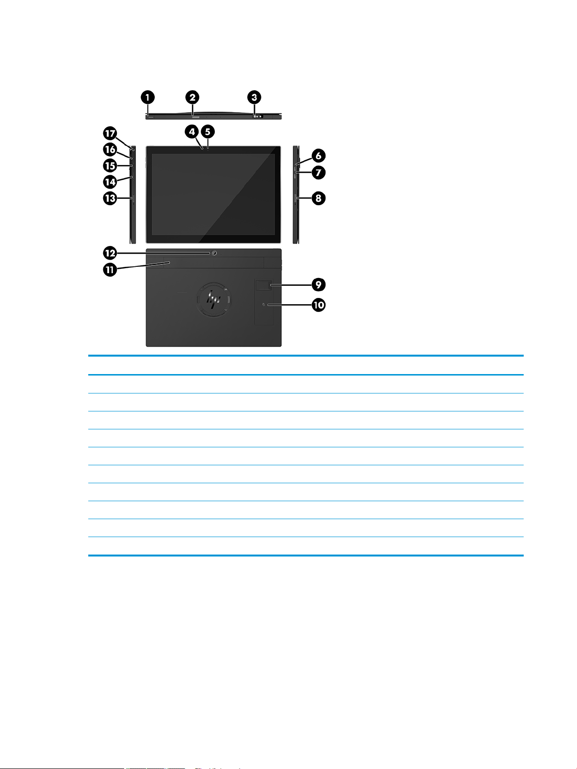
Mobility head unit features
Features
(1) Power button (10) Near Field Communications (NFC) (optional)
(2) Barcode scanner button (11) Hand strap
(3) Barcode scanner (optional) (12) Rear-facing webcam
(4) Webcam light (13) Barcode scanner button
(5) Webcam (14) SIM card door
(6) Charging light (15) Volume down button
(7) USB-C charging ports (2) (16) Volume up button
(8) Barcode scanner button (17) Audio jack
(9) Fingerprint reader (optional)
NOTE: You cannot have a WWAN (LTE) module and a barcode scanner in the same unit. You can have neither, or either, but not both.
2 Chapter 1 Product overview
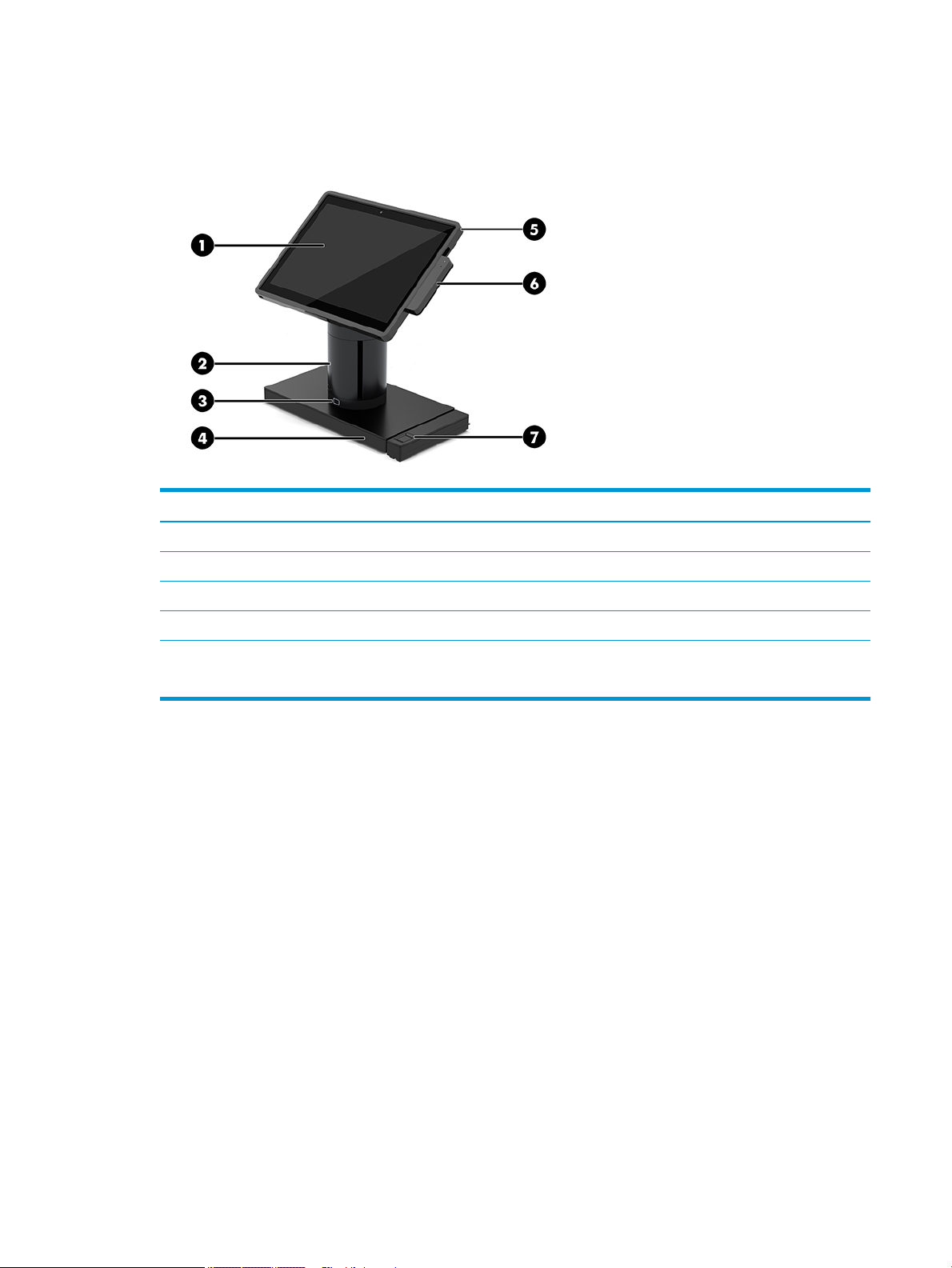
Integrated features
Other than the display, the integrated devices shown below are optional.
Features
(1) 12.3” 1920 × 1280 WUXGA display (5) HP Engage Go Mobile Retail Case
(2) HP Engage One Integrated Column Printer (6) Integrated MSR
(3) Docking lock release button (7) HP Engage One Biometric Fingerprint Reader
(4) Choice of two ElitePOS I/O Connectivity Bases
The display panel is an anti-glare WLED SVA 400 nits panel.
NOTE: The nits rating indicates the typical brightness of the panel prior to anti-glare coating.
Integrated features 3
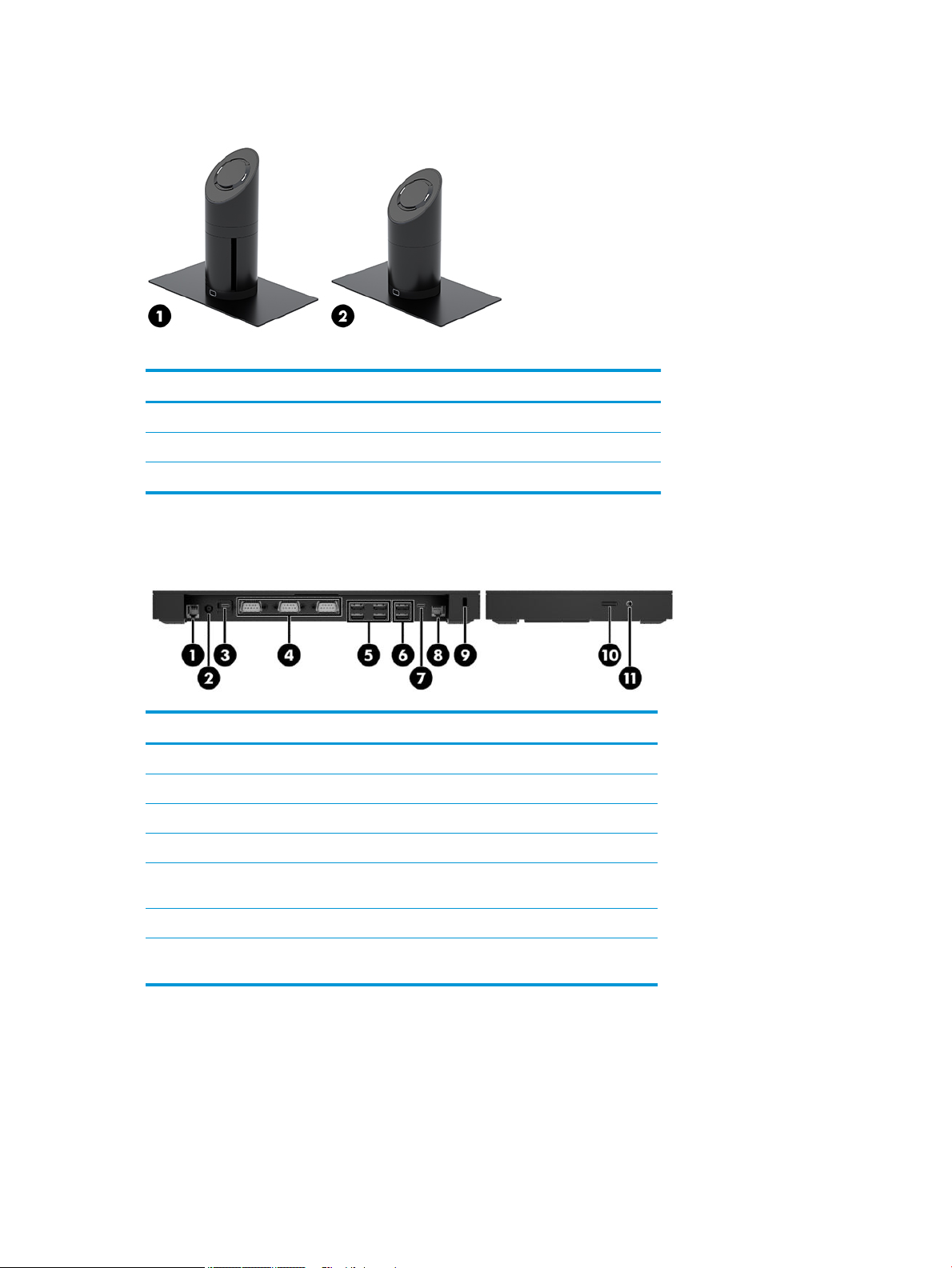
Dock options
Options
(1) Rotate/tilt dock with integrated column printer
(2) Rotate/tilt dock (with standard column)
NOTE: The docks are shown on a stability base.
HP Engage One Basic I/O Connectivity Base components
Basic components
(1) Cash drawer jack (7) USB Type-C port
(2) Power connector (8) RJ-45 (network) jack
(3) USB Type-C power port (9) Security cable slot
(4) Powered serial ports (3) (10) MicroSD card reader
(5) USB 2.0 ports (4) (11) Audio-out (headphone)/Audio-in
(microphone) jack
(6) USB 3.0 ports (2)
IMPORTANT: To avoid damage to the system, DO NOT plug a telephone cable into the cash
drawer jack.
4 Chapter 1 Product overview

HP Engage One Advanced I/O Connectivity Base components
Advanced components
(1) Cash drawer jack (7) USB 3.0 ports (4)
(2) Powered USB 12 V ports (2) (8) USB Type-C port
(3) Powered USB 24 V port (9) RJ-45 (network) jack
(4) Power connector (10) Security cable slot
(5) USB Type-C power port (11) MicroSD card reader
(6) Powered serial ports (2) (12) Audio-out (headphone)/Audio-in
(microphone) jack
IMPORTANT: To avoid damage to the system, DO NOT plug a telephone cable into the cash
drawer jack.
HP Engage One Advanced I/O Connectivity Base components 5
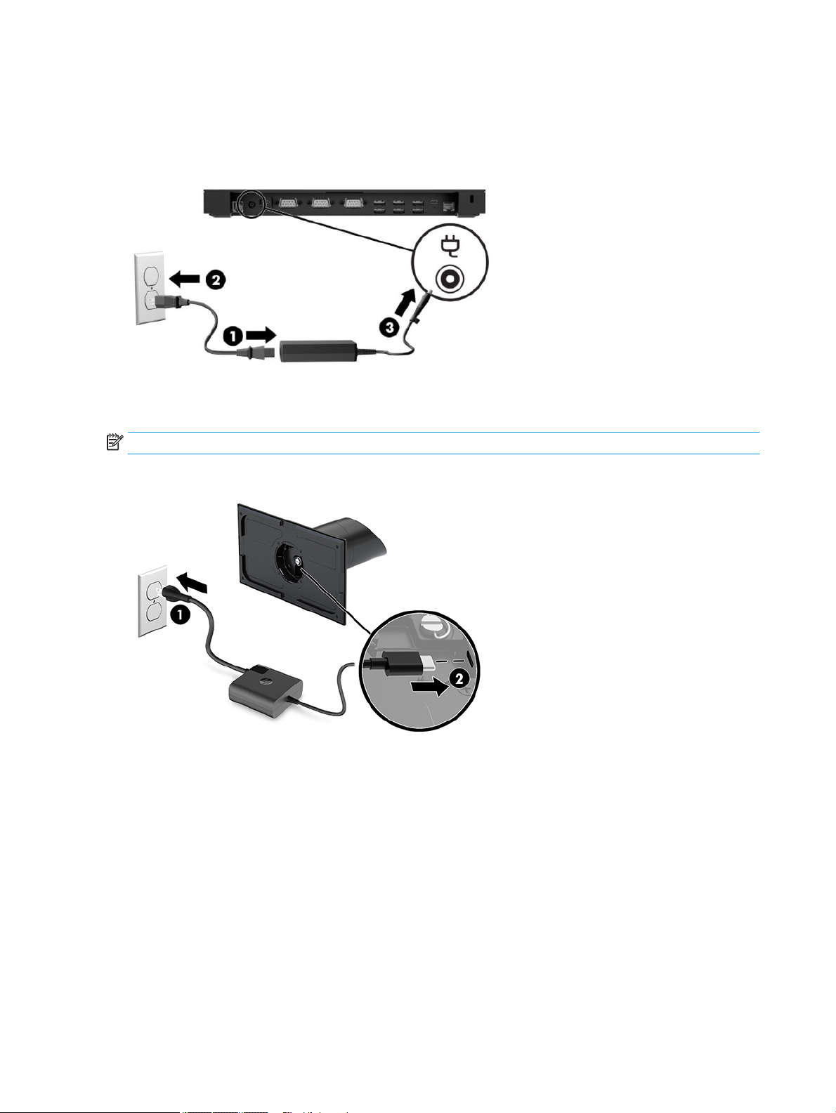
Connecting an AC adapter to power
To connect an AC adapter to the I/O connectivity base, connect one end of the power cord to the AC adapter (1)
and the other end to a grounded AC outlet (2), and then connect the AC adapter to the power connector on the
I/O connectivity base (3).
To connect an AC adapter to the mobility system when it is not connected to an I/O connectivity base, connect
the AC adapter to a grounded AC outlet (1), and then connect the power adapter’s USB Type-C connector to
the USB Type-C power port on the underside of the dock’s column (2).
NOTE: The image below is shown with a stability base.
6 Chapter 1 Product overview
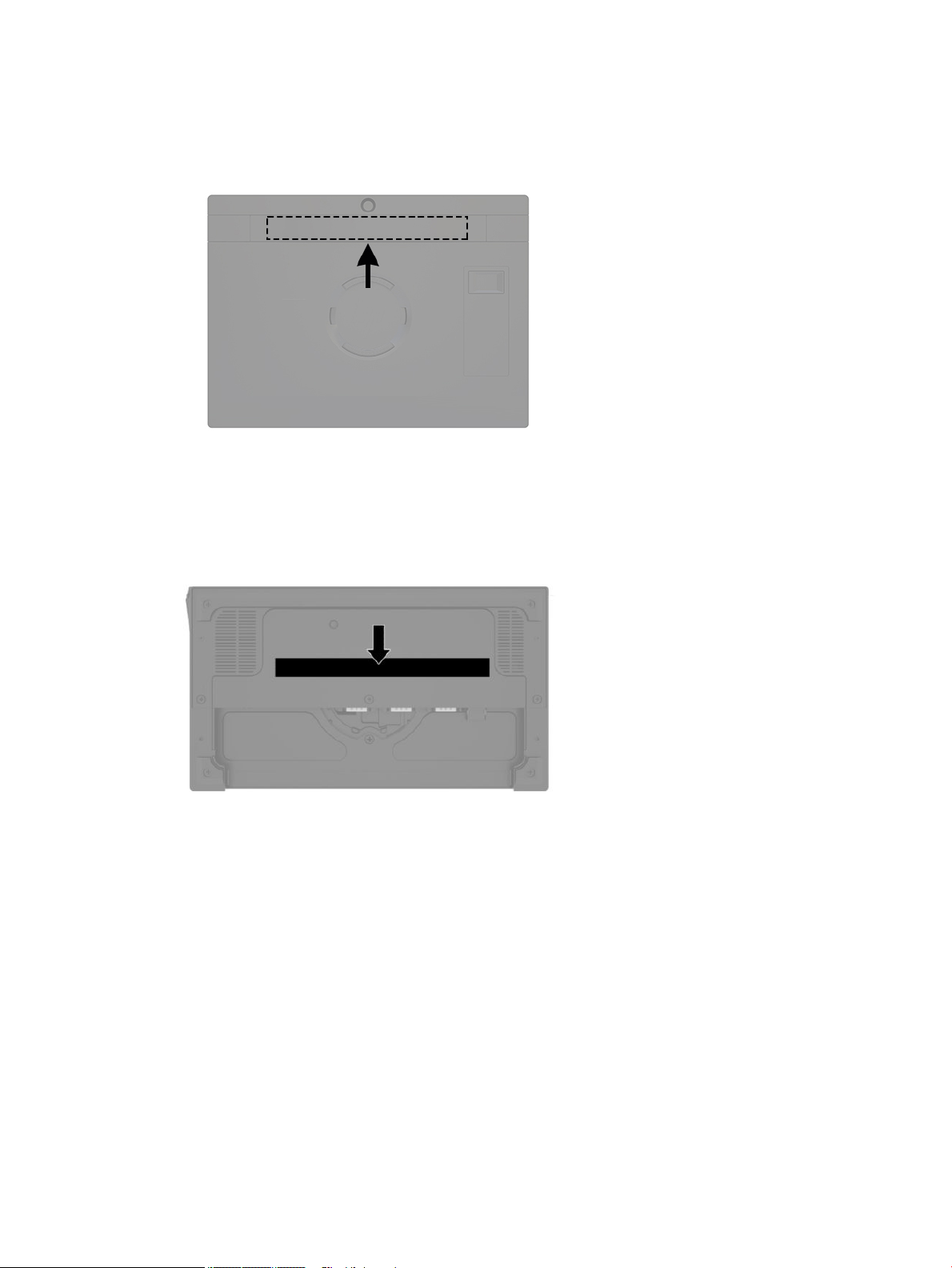
Mobility head unit serial number location
Each mobility head unit has a unique serial number and a product ID number that are located under the strap.
Keep these numbers available for use when contacting customer service for assistance.
I/O connectivity base serial number location
Each I/O connectivity base has a unique serial number and a product ID number that are located on the
exterior of the I/O connectivity base. Keep these numbers available for use when contacting customer service
for assistance.
Regulatory information is located in the base plate. Install the base plate back if it is removed.
Mobility head unit serial number location 7
2 Cable routing congurations
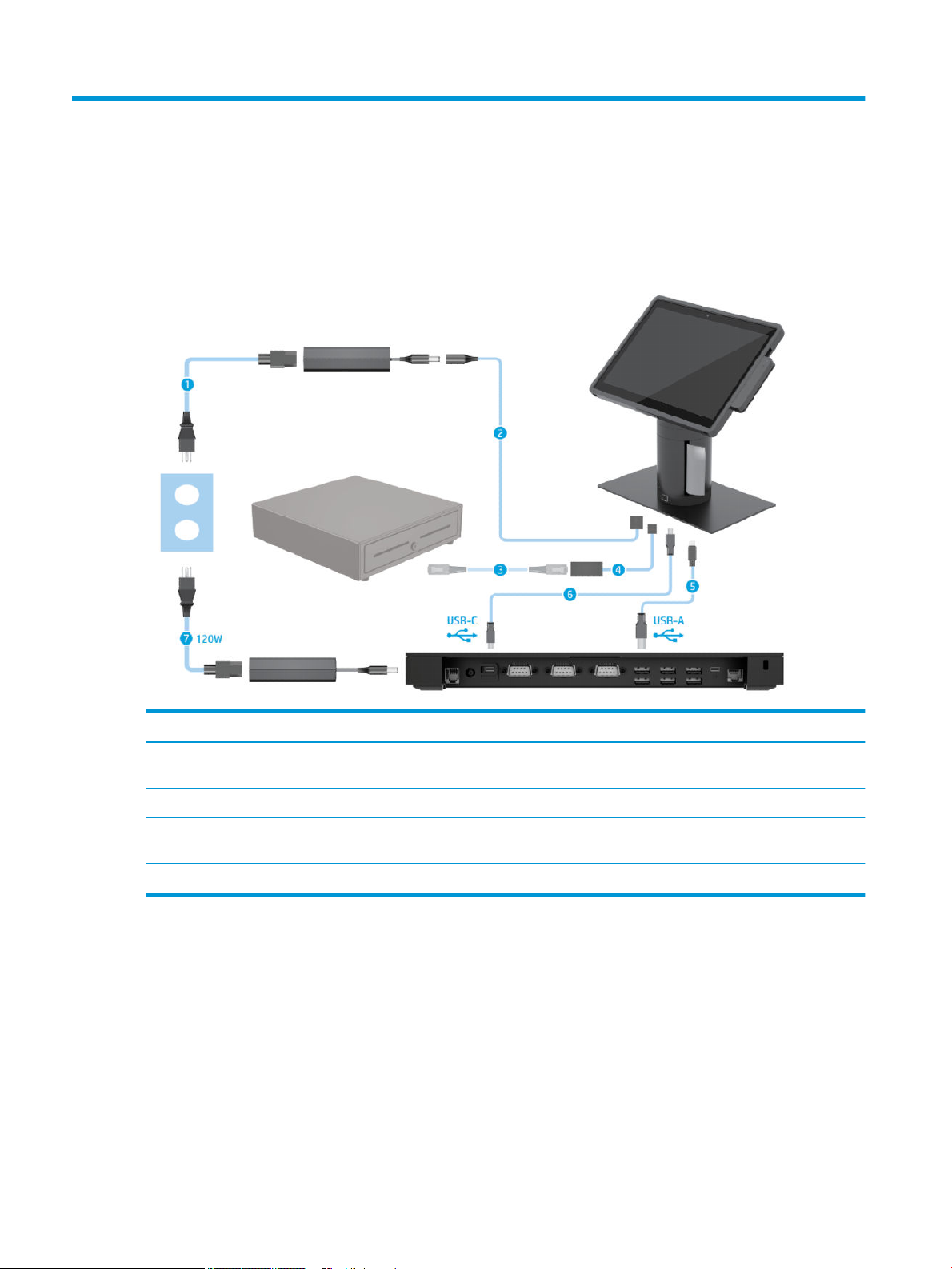
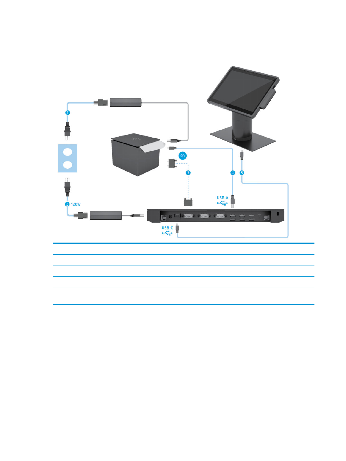
Cable matrix for HP Engage Go Convertible System with
integrated column printer and basic I/O connectivity base
Cables
(1) Column printer AC power cord (5) I/O connectivity base mini USB Type-B to USB Type-A data
cable
(2) Column printer AC adapter cable (6) I/O connectivity base USB Type-C cable
(3) Cash drawer cable (purchased separately with cash
drawer)
(4) Column printer cash drawer cable
(7) I/O connectivity base 120 W AC power cord
8 Chapter 2 Cable routing congurations
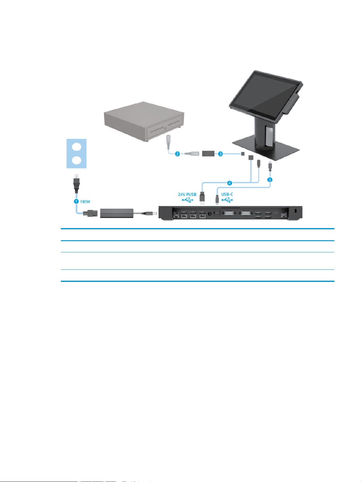
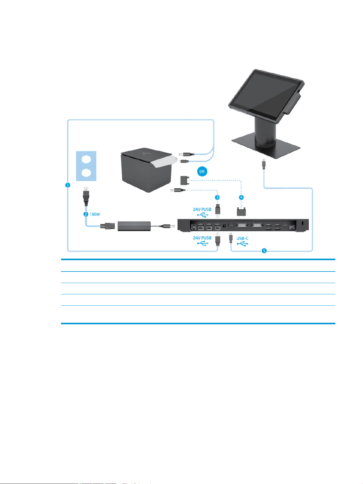
Cable matrix for HP Engage Go Convertible System with
integrated column printer and advanced I/O connectivity base
Cables
(1) I/O connectivity base 180 W AC power cord (4) Column printer 24 V PUSB power and data Y cable
(2) Cash drawer cable (purchased separately with cash
drawer)
(3) Column printer cash drawer cable
(5) I/O connectivity base USB Type-C cable
Cable matrix for HP Engage Go Convertible System with integrated column printer and advanced I/O
connectivity base
9
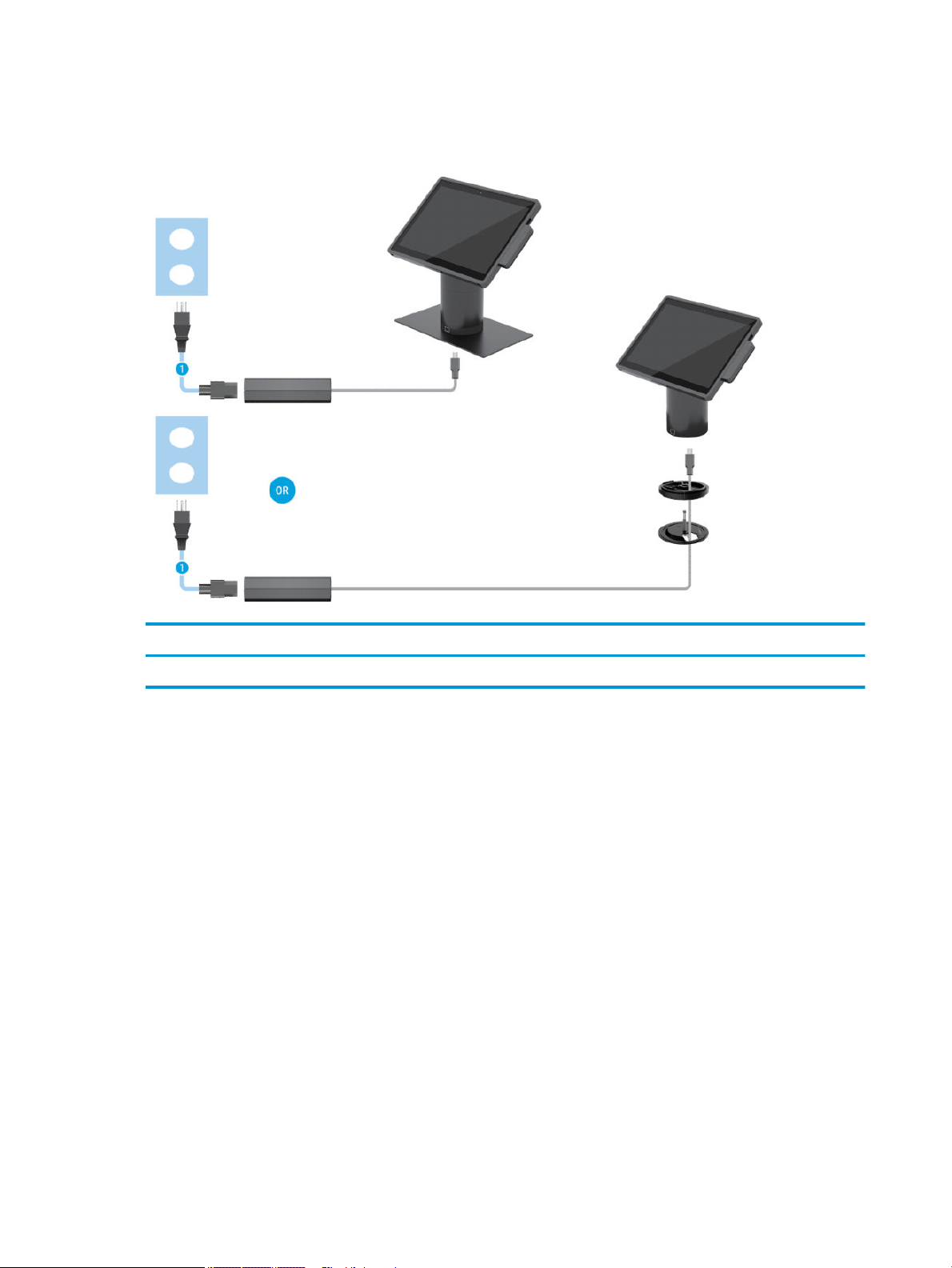
Cable matrix for HP Engage Go Convertible System without I/O connectivity base
Cables
(1) AC power cord
10 Chapter 2 Cable routing congurations
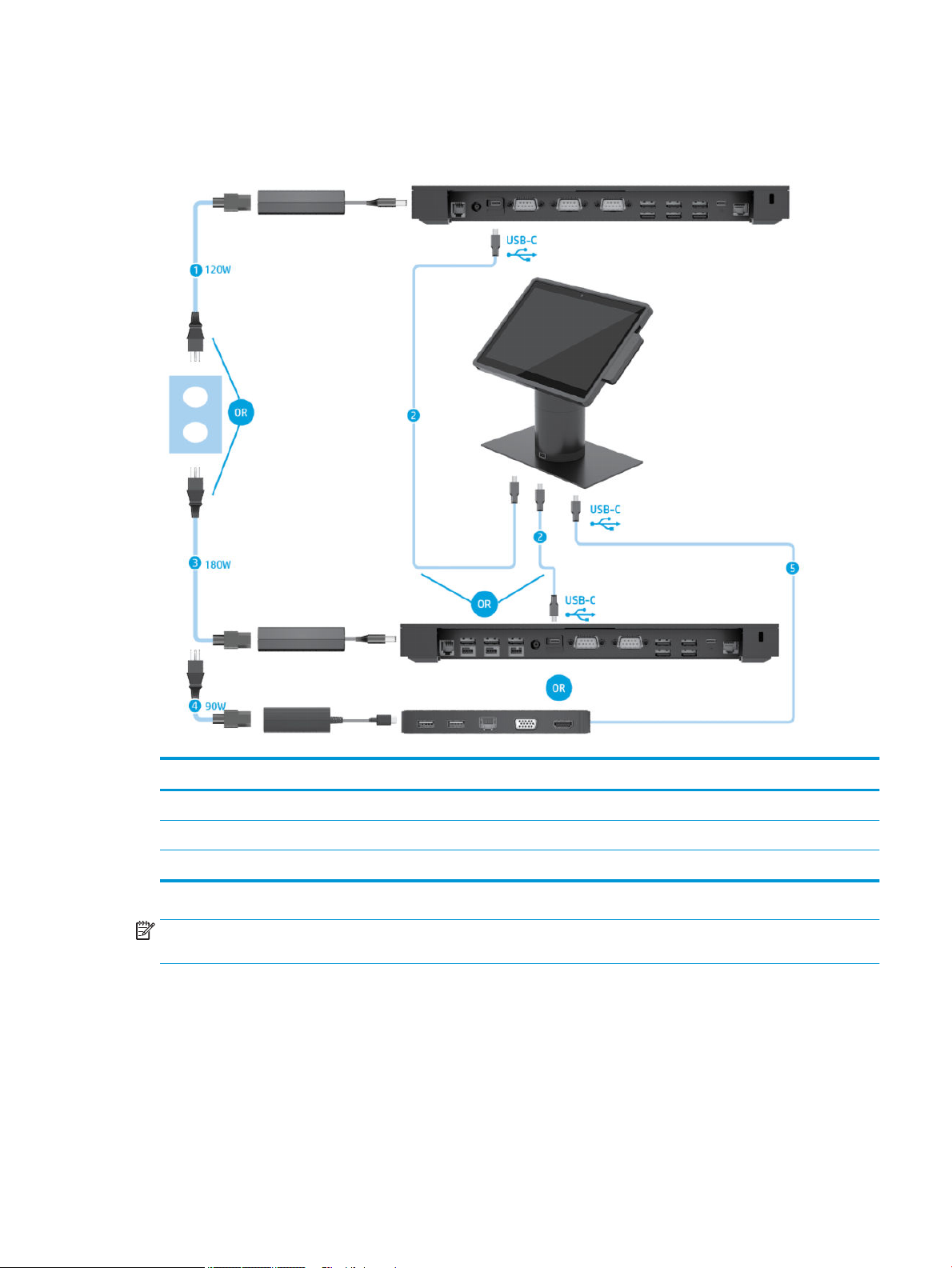
Cable matrix for HP Engage Go Convertible System with I/O connectivity base
Cables
(1) Basic I/O connectivity base 120 W AC power cord (4) USB-C mini dock 90 W AC power cord
(2) I/O connectivity base USB Type-C cable (5) USB-C mini dock captive USB Type-C cable
(3) Advanced I/O connectivity base 180 W AC power cord
NOTE: In the European region, the USB-C mini dock is sold as an aftermarket option kit only. In all other
regions, the USB-C mini dock is sold as drop-in-box option.
Cable matrix for HP Engage Go Convertible System with I/O connectivity base 11
Cable matrix for HP Engage Go Convertible System with basic I/O
connectivity base and standalone printer
Cables
(1) Printer AC power cord (4) Printer USB Type-A to Type-B data cable
(2) Basic I/O connectivity base 120 W AC power cord (5) Basic I/O connectivity base USB Type-C cable
(3) Printer serial data cable
IMPORTANT: Connect either the serial data cable (3) or the USB Type-A data cable (4) between the I/O connectivity base and the
printer. Do not connect both.
12 Chapter 2 Cable routing congurations
Cable matrix for HP Engage Go Convertible System with
advanced I/O connectivity base and standalone printer
Cables
(1) Printer 24 V PUSB power and data Y cable (4) Printer serial data cable
(2) Advanced I/O connectivity base 180 W AC power cord (5) Advanced I/O connectivity base USB Type-C cable
(3) Printer 24 V PUSB power cable
IMPORTANT: Connect either the 24 V PUSB power and data Y cable (1) or the 24 V PUSB power cable (3) and serial data cable (4)
between the I/O connectivity base and the printer. Do not connect all three.
Cable matrix for HP Engage Go Convertible System with advanced I/O connectivity base and standalone
printer
13
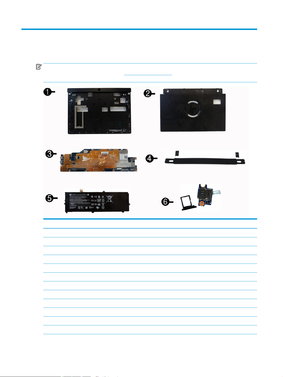
3 Illustrated parts catalog
NOTE: HP continually improves and changes product parts. For complete and current information on
supported parts for your computer, go to http://partsurfer.hp.com, select your country or region, and then
follow the on-screen instructions.
Item Description
(1) Mid frame (includes cameras, speakers, power connector/volume board and mid plate bezel)
Black, with barcode
Black, without barcode
White, with barcode
White, without barcode
(2) Backplate (includes gold communication cable)
Black, with ngerprint reader, without NFC module
Black, without ngerprint reader, without NFC module
Black, with ngerprint reader, with NFC module
Black, without ngerprint reader, with NFC module
White, with ngerprint reader, without NFC module
White, without ngerprint reader, without NFC module
14 Chapter 3 Illustrated parts catalog

Item Description
White, with ngerprint reader, with NFC module
White, without ngerprint reader, with NFC module
(3) System board (includes heat sink)
Intel Core i5-7Y57 processor
Intel Core M3-7Y30 processor
Intel Pentium 4410Y processor
(4) Hand strap
Black
White
(5) Battery
(6) SIM board
* Display panel
NOTE: The display panel is spared with all required parts.
* Solid-state drive, M.2
256 GB, TLC, PCIe
128 GB, SATA-3, TLC
* WLAN modules
Intel Wireless-AC 8265 802.11ac 2x2 WiFi + Bluetooth 4.2 Combo Adapter (vPro)
Intel Wireless-AC 8265 802.11ac 2x2 WiFi + Bluetooth 4.2 Combo Adapter (non-vPro)
* WWAN modules
LTE CAT4: Huawei HP lt4132, LTE/HSPA+ w/GPS M.2
* AC adapter, 65 W (external)
* Power cord
1.8 m
1.0 m
Duckhead
* Column
With printer
Without printer
* Magnetic strip reader
* HP USB-C Mini Dock
15

4 Routine care, SATA drive guidelines, and
disassembly preparation
This chapter provides general service information for the computer. Adherence to the procedures and
precautions described in this chapter is essential for proper service.
CAUTION: When the computer is plugged into an AC power source, voltage is always applied to the system
board. You must disconnect the power cord from the power source before opening the computer to prevent
system board or component damage.
Electrostatic discharge information
A sudden discharge of static electricity from your nger or other conductor can destroy static-sensitive
devices or microcircuitry. Often the spark is neither felt nor heard, but damage occurs. An electronic device
exposed to electrostatic discharge (ESD) may not appear to be aected at all and can work perfectly
throughout a normal cycle. The device may function normally for a while, but it has been degraded in the
internal layers, reducing its life expectancy.
Networks built into many integrated circuits provide some protection, but in many cases, the discharge
contains enough power to alter device parameters or melt silicon junctions.
Generating static
The following table shows that:
●
Dierent activities generate dierent amounts of static electricity.
●
Static electricity increases as humidity decreases.
Relative Humidity
Event 55% 40% 10%
Walking across carpet
Walking across vinyl oor
Motions of bench worker
Removing DIPs from plastic tube
Removing DIPs from vinyl tray
Removing DIPs from Styrofoam
Removing bubble pack from PCB
Packing PCBs in foam-lined box
These are then multi-packaged inside plastic tubes, trays, or Styrofoam.
7,500 V
3,000 V
400 V
400 V
2,000 V
3,500 V
7,000 V
5,000 V
15,000 V
5,000 V
800 V
700 V
4,000 V
5,000 V
20,000 V
11,000 V
35,000 V
12,000 V
6,000 V
2,000 V
11,500 V
14,500 V
26,500 V
21,000 V
NOTE: 700 volts can degrade a product.
16 Chapter 4 Routine care, SATA drive guidelines, and disassembly preparation

Preventing electrostatic damage to equipment
Many electronic components are sensitive to ESD. Circuitry design and structure determine the degree of
sensitivity. The following packaging and grounding precautions are necessary to prevent damage to electric
components and accessories.
●
To avoid hand contact, transport products in static-safe containers such as tubes, bags, or boxes.
●
Protect all electrostatic parts and assemblies with conductive or approved containers or packaging.
●
Keep electrostatic sensitive parts in their containers until they arrive at static-free stations.
●
Place items on a grounded surface before removing them from their container.
●
Always be properly grounded when touching a sensitive component or assembly.
●
Avoid contact with pins, leads, or circuitry.
●
Place reusable electrostatic-sensitive parts from assemblies in protective packaging or conductive
foam.
Personal grounding methods and equipment
Use the following equipment to prevent static electricity damage to equipment:
●
Wrist straps are exible straps with a maximum of one-megohm ± 10% resistance in the ground cords.
To provide proper ground, a strap must be worn snug against bare skin. The ground cord must be
connected and t snugly into the banana plug connector on the grounding mat or workstation.
●
Heel straps/Toe straps/Boot straps can be used at standing workstations and are compatible with
most types of shoes or boots. On conductive oors or dissipative oor mats, use them on both feet with
a maximum of one-megohm ± 10% resistance between the operator and ground.
Static Shielding Protection Levels
Method Voltage
Antistatic plastic
Carbon-loaded plastic
Metallized laminate
Grounding the work area
To prevent static damage at the work area, use the following precautions:
●
Cover the work surface with approved static-dissipative material. Provide a wrist strap connected to the
work surface and properly grounded tools and equipment.
●
Use static-dissipative mats, foot straps, or air ionizers to give added protection.
●
Handle electrostatic sensitive components, parts, and assemblies by the case or PCB laminate. Handle
them only at static-free work areas.
●
Turn o power and input signals before inserting and removing connectors or test equipment.
1,500
7,500
15,000
●
Use xtures made of static-safe materials when xtures must directly contact dissipative surfaces.
●
Keep work area free of nonconductive materials such as ordinary plastic assembly aids and Styrofoam.
●
Use eld service tools, such as cutters, screwdrivers, and vacuums, that are conductive.
Electrostatic discharge information 17

Recommended materials and equipment
Materials and equipment that are recommended for use in preventing static electricity include:
●
Antistatic tape
●
Antistatic smocks, aprons, or sleeve protectors
●
Conductive bins and other assembly or soldering aids
●
Conductive foam
●
Conductive tabletop workstations with ground cord of one-megohm +/- 10% resistance
●
Static-dissipative table or oor mats with hard tie to ground
●
Field service kits
●
Static awareness labels
●
Wrist straps and footwear straps providing one-megohm +/- 10% resistance
●
Material handling packages
●
Conductive plastic bags
●
Conductive plastic tubes
●
Conductive tote boxes
●
Opaque shielding bags
●
Transparent metallized shielding bags
●
Transparent shielding tubes
Operating guidelines
To prevent overheating and to help prolong the life of the computer:
●
Keep the computer away from excessive moisture, direct sunlight, and extremes of heat and cold.
●
Operate the computer on a sturdy, level surface. Leave a 10.2-cm (4-inch) clearance on all vented sides
of the computer and above the display to permit the required airow.
●
Never restrict the airow into the computer by blocking any vents or air intakes. Do not place the
keyboard, with the keyboard feet down, directly against the front of the desktop unit as this also
restricts airow.
●
Occasionally clean the air vents on all vented sides of the computer. Lint, dust, and other foreign matter
can block the vents and limit the airow. Be sure to unplug the computer before cleaning the air vents.
●
Never operate the computer with the covers removed.
●
Keep liquids away from the computer and keyboard.
●
Install or enable power management functions of the operating system or other software, including
sleep states.
Service considerations
Listed below are some of the considerations that you should keep in mind during the disassembly and
assembly of the computer.
18 Chapter 4 Routine care, SATA drive guidelines, and disassembly preparation

Tools and software requirements
To service the computer, you need the following:
●
Flat-bladed screwdriver
●
Non-marking, non-conductive pry tool
●
Phillips #2 screwdriver
●
Diagnostics software
Screws
The screws used in the computer are not interchangeable. They may have standard or metric threads and may
be of dierent lengths. If an incorrect screw is used during the reassembly process, it can damage the unit. HP
strongly recommends that all screws removed during disassembly be kept with the part that was removed,
then returned to their proper locations.
CAUTION: Metric screws have a black nish. U.S. screws have a silver nish and are used on hard drives only.
CAUTION: As each subassembly is removed from the computer, it should be placed away from the work area
to prevent damage.
Cables and connectors
Most cables used throughout the unit are at, exible cables. These cables must be handled with care to
avoid damage. Apply only the tension required to seat or unseat the cables during insertion or removal from
the connector. Handle cables by the connector whenever possible. In all cases, avoid bending or twisting the
cables, and ensure that the cables are routed in such a way that they cannot be caught or snagged by parts
being removed or replaced.
CAUTION: When servicing this computer, ensure that cables are placed in their proper location during the
reassembly process. Improper cable placement can damage the computer.
Hard Drives
Handle hard drives as delicate, precision components, avoiding all physical shock and vibration. This applies
to failed drives as well as replacement spares.
●
●
●
●
●
●
●
If a drive must be mailed, place the drive in a bubble-pack mailer or other suitable protective packaging
and label the package “Fragile: Handle With Care.”
Do not remove hard drives from the shipping package for storage. Keep hard drives in their protective
packaging until they are actually mounted in the CPU.
Avoid dropping drives from any height onto any surface.
If you are inserting or removing a hard drive, turn o the computer. Do not remove a hard drive while the
computer is on or in standby mode.
Before handling a drive, ensure that you are discharged of static electricity. While handling a drive, avoid
touching the connector. For more information about preventing electrostatic damage, refer to
Electrostatic discharge information on page 16
Do not use excessive force when inserting a drive.
Avoid exposing a hard drive to liquids, temperature extremes, or products that have magnetic elds
such as displays or speakers.
Service considerations 19
Lithium coin cell battery
The battery that comes with the computer provides power to the real-time clock and has a minimum lifetime
of about three years.
See the appropriate removal and replacement chapter for the chassis you are working on in this guide for
instructions on the replacement procedures.
WARNING! This computer contains a lithium battery. There is a risk of re and chemical burn if the battery is
handled improperly. Do not disassemble, crush, puncture, short external contacts, dispose in water or re, or
expose it to temperatures higher than 140ºF (60ºC). Do not attempt to recharge the battery.
NOTE: Batteries, battery packs, and accumulators should not be disposed of together with the general
household waste. In order to forward them to recycling or proper disposal, please use the public collection
system or return them to HP, their authorized partners, or their agents.
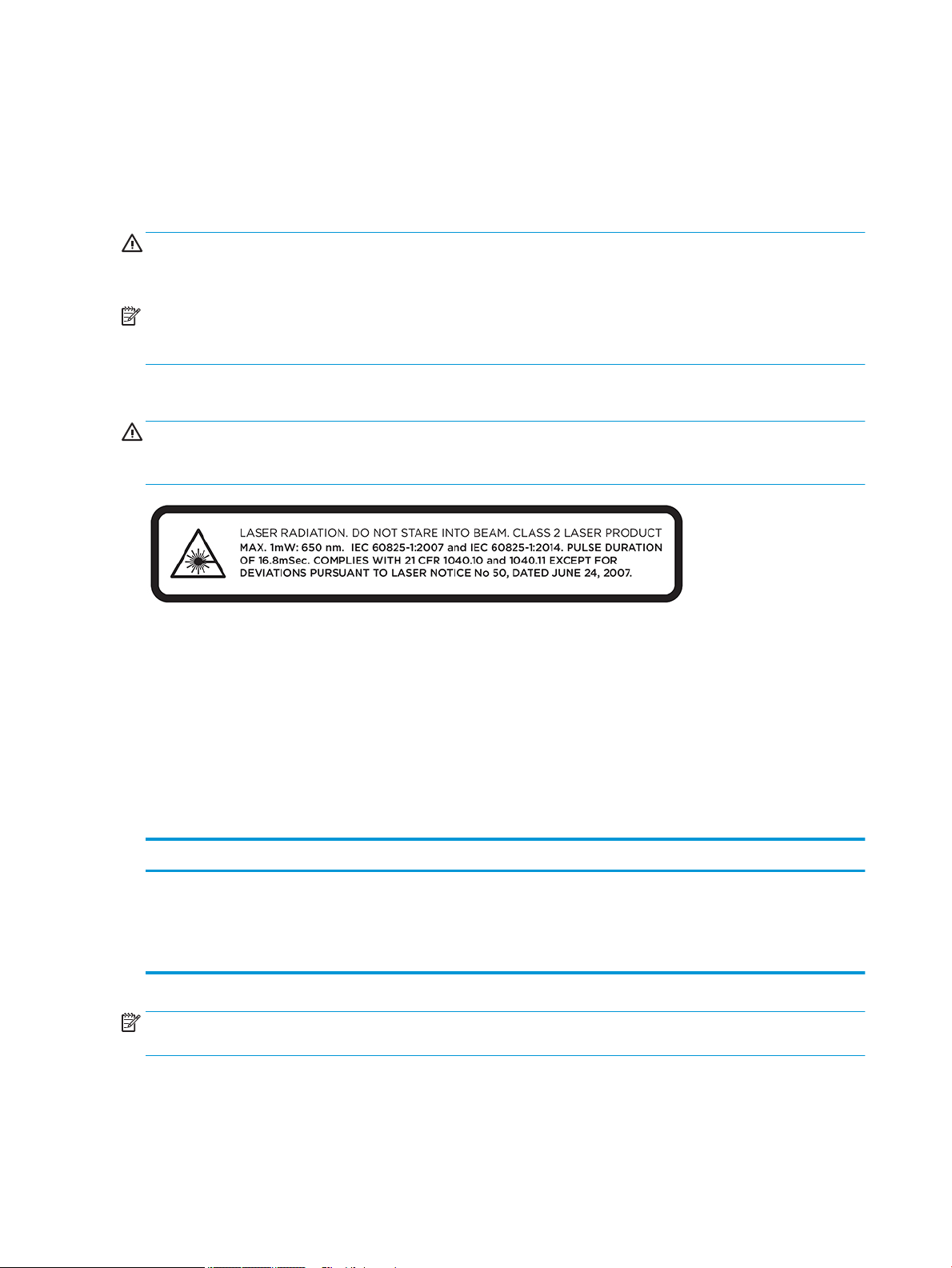
Laser compliance
WARNING! Use of controls or adjustments, or performance of procedures other than those specied in the
laser product installation guide, may result in hazardous radiation exposure. To reduce the risk of exposure to
hazardous radiation:
Input power
The power information in this section may be helpful if you plan to travel internationally with the computer.
The computer operates on DC power, which can be supplied by an AC or a DC power source. The AC power
source must be rated at 100–240 V, 50–60 Hz. Although the computer can be powered from a standalone DC
power source, it should be powered only with an AC adapter or a DC power source supplied and approved by
HP for use with this computer.
The computer can operate on DC power within the following specications. The voltage and current for your
computer is located on the regulatory label.
Input power Rating
Operating voltage and current 5 V dc @ 3 A / 9 V dc @ 3 A / 10 V dc @ 5 A / 12 V dc @ 5 A / 15 V dc @ 4.33
NOTE: This product is designed for IT power systems in Norway with phase-to-phase voltage not exceeding
240 V ms.
A / 20 V dc @ 3.25 A – 65 W USB-C
HP Engage One Basic I/O Connectivity Base: 120 W (19.5 V / 6.15 A)
HP Engage One Advanced I/O Connectivity Base: 180 W (19.5 V / 9.23 A)
20 Chapter 4 Routine care, SATA drive guidelines, and disassembly preparation

Operating environment
Factor Metric U.S.
Temperature
Operating (writing to optical disc) 5°C to 35°C 41°F to 95°F
Nonoperating -20°C to 60°C -4°F to 140°F
Relative humidity (noncondensing)
Operating 10% to 90% 10% to 90%
Nonoperating 5% to 95% 5% to 95%
Maximum altitude (unpressurized)
Operating -15 m to 3,048 m -50 ft to 10,000 ft
Nonoperating -15 m to 12,192 m -50 ft to 40,000 ft
Operating guidelines and routine care
Follow the guidelines below to properly set up and care for the system:
●
HP recommends a 17 mm clearance around the vents on the mobility head unit and I/O connectivity
base for heat dissipation.
●
Keep the system away from excessive moisture, direct sunlight, and extremes of heat and cold.
●
Never operate the system with any access panels removed.
●
Do not stack systems on top of each other or place them so near each other that they are subject to each
other’s recirculated or preheated air.
●
If the system is to be operated within a separate enclosure, intake and exhaust ventilation must be
provided on the enclosure, and the same operating guidelines listed above still apply.
●
Keep liquids away from the mobility system and I/O connectivity base.
●
Never cover the vents on the mobility system or I/O connectivity base with any type of material.
●
Install or enable power management functions of the operating system or other software, including
sleep states.
●
Turn o the mobility system before you do either of the following:
–
Wipe the exterior with a soft, damp cloth as necessary. Using cleaning products may discolor or
damage the nish.
–
Occasionally clean the air vents on all vented sides of the mobility system. Lint, dust, and other
foreign matter can block the vents and limit the airow.
NOTE: For more information on your retail system care and maintenance, refer to “Retail Point of Sales
Systems - Routine Care and Maintenance” available at http://www.hp.com/support.
Touch screen maintenance
Keep your display and touch sensor clean. The touch sensor requires very little maintenance. HP recommends
that you periodically clean the glass touch sensor surface. Be sure to turn o your display before cleaning.
Typically, an isopropyl alcohol and water solution ratio of 50:50 is the best cleaning agent for your touch
Service considerations 21

sensor. It is important to avoid using any caustic chemicals on the touch sensor. Do not use any vinegar-based
solutions.
Apply the cleaner with a soft, lint-free cloth. Avoid using gritty cloths. Always dampen the cloth and then
clean the sensor. Be sure to spray the cleaning liquid onto the cloth, not the sensor, so that drips do not seep
inside the display or stain the bezel.
MSR maintenance
To clean the MSR (magnetic stripe reader), swipe a standard cleaning card through the MSR a couple of times.
You can order a standard cleaning card online. You can also put a thin oil-free cloth around a credit card.
Cleaning the printer
Because of the way the printer sits while in use, it is likely there is a buildup of paper and other debris from
the knife. HP recommends that you keep the printer in working order by periodically cleaning the debris from
the printer.
To clean the printer, open the cover, remove the paper roll, and then use a can of compressed air to blow the
debris out from the bottom plate where it accumulates.
Cleaning I/O ports
The mobility system has a series of ports. Dust and debris can collect in these ports, which can reduce
connectivity and performance. Use a battery-powered vacuum to remove any debris that has accumulated in
and around these ports.
Updating drivers and rmware
HP recommends that you regularly download and install the latest drivers and rmware updates to help
enhance system performance, resolve known issues, and avoid replacing parts unnecessarily.
Go to http://www.hp.com/support to download and install the latest drivers and BIOS updates for your
specic Retail Point of Sale model.
22 Chapter 4 Routine care, SATA drive guidelines, and disassembly preparation
 Loading...