

Page 1

HP xw9400 Workstation Service and Technical
Reference Guide
Page 2

Copyright Information
© 2008-2009 Copyright Hewlett-Packard
Development Company, L.P.
Warranty
Hewlett-Packard Company shall not be liable
for technical or editorial errors or omissions
contained herein or for incidental or
consequential damages in connection with
the furnishing, performance, or use of this
material. The information in this document is
provided “as is” without warranty of any kind,
including, but not limited to, the implied
warranties of merchantability and fitness for
a particular purpose, and is subject to
change without notice. The warranties for HP
products are set forth in the express limited
warranty statements accompanying such
products.
Nothing herein should be construed as
constituting and additional warranty.
This document contains proprietary
information that is protected by copyright. No
part of this document may be photocopied,
reproduced, or translated to another
language without the prior written consent of
Hewlett-Packard Company.
Trademark Credits
The HP Invent logo is a trademark of HewlettPackard Company in the U.S. and other
countries.
Microsoft and Windows are trademarks of
Microsoft Corporation.
UNIX is a registered trademark of The Open
Group.
Intel and Xeon are registered trademarks of
Intel Corporation in the U.S. and other
countries.
Energy Star is U.S. registered mark of the
United States Environmental Protection
Agency.
434615-009
Ninth Edition, June 2009
Page 3

Table of contents
1 Product overview
Product features ................................................................................................................................... 1
Exploded view ...................................................................................................................... 1
Front panel components ..................................................................................................... 3
Rear panel components ...................................................................................................... 4
Serial number and COA label location ................................................................................. 4
Product specifications ......................................................................................................................... 5
Power supply and cooling .................................................................................................... 6
Power supply specifications ................................................................................ 8
Power consumption and heat dissipation ............................................................ 8
System fans and airflow ..................................................................................... 9
Resetting the power supply ................................................................................ 9
Power cord requirements .................................................................................... 9
Environmental specifications ............................................................................................ 10
PCI card slot power specification ....................................................................................... 10
Chipkill support ................................................................................................................................... 11
ENERGY STAR Qualification ............................................................................................................. 11
Multi-core processors ......................................................................................................................... 12
2 Setting up the operating system
Setting up the Microsoft operating system ......................................................................................... 14
Installing or upgrading device drivers ................................................................................ 14
Transferring files and settings to your Windows workstation ............................................. 14
Setting up Red Hat Enterprise Linux .................................................................................................. 15
Installing with the HP driver CD ......................................................................................... 15
Installing and customizing Red Hat-enabled workstations ................................................ 16
Verifying hardware compatibility ....................................................................... 16
Setting up Novell SLED ...................................................................................................................... 16
Updating the workstation .................................................................................................................... 16
Updating the workstation after first boot ............................................................................ 16
Upgrading the BIOS ........................................................................................................... 16
Determining current BIOS ................................................................................. 17
Upgrading BIOS ................................................................................................ 18
Upgrading device drivers ................................................................................................... 18
3 Restoring the operating system
Restore methods ................................................................................................................................ 19
Ordering backup software .................................................................................................................. 20
ENWW iii
Page 4

Restoring Windows Vista ................................................................................................................... 20
Ordering the RestorePlus! media ...................................................................................... 20
Restoring the operating system ......................................................................................... 20
Restoring Windows XP Professional .................................................................................................. 21
Creating RestorePlus! media ............................................................................................. 21
Creating HP Backup and Recovery (HPBR) media ........................................................... 22
Restoring the operating system ......................................................................................... 23
Using RestorePlus! ........................................................................................... 23
Using HPBR ..................................................................................................... 23
Using the recovery partition .............................................................................. 23
Restoring Novell SLED ....................................................................................................................... 23
Creating restore media ...................................................................................................... 23
4 System management
Computer Setup (F10) Utility .............................................................................................................. 25
BIOS ROM ......................................................................................................................... 26
Using Computer Setup (F10) Utility ................................................................................... 27
Computer Setup (F10) Utility menu .................................................................................. 28
Desktop management ........................................................................................................................ 36
Initial configuration and deployment .................................................................................. 36
Remote system installation ................................................................................................ 37
Managing and updating software ....................................................................................... 37
HP Client Manager software ............................................................................. 37
Altiris Client Management solutions .................................................................. 38
System Software Manager ................................................................................ 38
Proactive Change Notification ........................................................................... 39
Subscriber’s Choice .......................................................................................... 39
ROM flash .......................................................................................................................... 39
Remote ROM flash ............................................................................................ 39
HPQFlash .......................................................................................................... 39
FailSafe Boot Block ROM ................................................................................. 40
Replicating the setup ......................................................................................... 41
Copying to a single workstation ........................................................ 41
Copying to multiple workstations ...................................................... 41
Dual-state power button .................................................................................... 42
Worldwide web site ........................................................................................... 43
Building blocks and partners ............................................................................. 43
Asset tracking and security ................................................................................................ 43
Password security ............................................................................................. 44
Establishing a setup password in the Computer Setup (F10)
Utility ................................................................................................. 45
Establishing a power-on password in the Computer Setup (F10)
Utility ................................................................................................. 45
Entering a power-on password ......................................................... 46
iv ENWW
Page 5

Entering a setup password ............................................................... 46
Changing a power-on or setup password ......................................... 46
Deleting a power-on or setup password ............................................................ 47
National keyboard delimiter characters ............................................ 47
Clearing passwords .......................................................................... 47
Hood sensor (Smart Cover Sensor) .................................................................. 48
Setting the hood sensor protection level .......................................... 48
Cable lock provision (optional) .......................................................................... 48
Security lock (optional) ...................................................................................... 48
Universal chassis clamp lock (optional) ............................................................ 48
Access panel key lock ....................................................................................... 49
Fault notification and recovery ........................................................................................... 49
Drive Protection System .................................................................................... 49
ECC fault prediction and pre-failure warranty ................................................... 49
Thermal sensors ............................................................................................... 49
5 Removal and replacement procedures
Warnings and cautions ....................................................................................................................... 50
Service considerations ....................................................................................................................... 51
Read cautions, warnings, and safety precautions ............................................................. 51
Electrostatic discharge information .................................................................................... 51
Generating static ............................................................................................... 52
Preventing electrostatic damage to equipment ................................................. 52
Personal grounding methods and equipment ................................................... 53
Grounding the work area ................................................................................... 53
Recommended materials and equipment ......................................................... 53
Required tools and software .............................................................................................. 54
Screws ............................................................................................................................... 54
Special handling of components ........................................................................................ 54
Cables and connectors ..................................................................................... 54
Hard drives ........................................................................................................ 54
Lithium coin cell battery ..................................................................................... 55
Customer Self Repair ......................................................................................................................... 55
Pre-disassembly procedures .............................................................................................................. 55
System board components ................................................................................................................. 56
System board architecture ................................................................................................................. 57
Removing and replacing components ................................................................................................ 58
Disassembly order ............................................................................................................. 59
Security lock (optional) ...................................................................................................... 61
Cable lock (optional) .......................................................................................................... 61
Universal chassis clamp lock (optional) ............................................................................. 62
Access panel ..................................................................................................................... 63
Front bezel ......................................................................................................................... 64
ENWW v
Page 6

Bezel blanks ..................................................................................................................... 64
Hood sensor (Smart cover sensor) .................................................................................... 65
Front panel I/O device assembly ....................................................................................... 66
Power button assembly and system speaker .................................................................... 67
Power supply ..................................................................................................................... 69
System fan ......................................................................................................................... 70
Memory fan ........................................................................................................................ 71
Memory .............................................................................................................................. 72
Memory module features ................................................................................. 72
Memory module requirements .......................................................................... 72
Removing memory module ............................................................................... 73
Installing a memory module .............................................................................. 75
PCI slots ............................................................................................................................ 77
PCI retainer ....................................................................................................... 78
Removing the PCI retainer ............................................................... 78
Installing the PCI retainer ................................................................. 78
PCI retention clamp ........................................................................................... 80
PCI Express ...................................................................................................... 81
Removing PCI or PCI Express cards ................................................................ 82
PCI or PCI Express installation ......................................................................... 83
Front fan removal ............................................................................................................... 84
Front fan jumper cable installation ..................................................................................... 86
Battery ............................................................................................................................... 88
Power connections to drives .............................................................................................. 89
Optical drive ...................................................................................................................... 90
Replacing the SATA optical drive data cable .................................................... 92
Notice for Blu-ray optical drives ........................................................................ 92
Blu-ray movie playback .................................................................... 92
Blu-ray movie playback compatibility and update ............................. 92
Diskette drive (optional) ..................................................................................................... 93
Hard drive ......................................................................................................................... 95
Replacing a hard drive ...................................................................................... 95
Removing a hard drive ..................................................................... 95
Installing a hard drive ....................................................................... 96
Installing a hard drive in the fifth hard drive bay ................................................ 98
Liquid cooling unit .............................................................................................................. 99
Removing the liquid cooling unit ....................................................................... 99
Installing a liquid cooling unit .......................................................................... 103
Replacing the liquid cooling unit VRD fan ....................................................... 110
Removing the VRD fan ................................................................... 110
Installing the VRD fan ..................................................................... 111
Processor heatsink .......................................................................................................... 113
Removing the CPU heatsink ........................................................................... 113
Replacing the CPU heatsink ........................................................................... 115
vi ENWW
Page 7

Processor ......................................................................................................................... 117
Removing the processor ................................................................................. 117
Replacing the processor ................................................................................. 119
System board ................................................................................................................... 120
Removing the system board ........................................................................... 120
Replacing the System Board ........................................................................... 120
Product recycling .............................................................................................................................. 121
6 System diagnostics and troubleshooting
HP troubleshooting resources and tools .......................................................................................... 122
HP Help and Support Center ........................................................................................... 122
E-support ......................................................................................................................... 122
Troubleshooting a problem ............................................................................. 123
Instant Support and Active Chat ..................................................................... 123
Customer Advisories, Customer and Security Bulletins, and Customer
Notices ............................................................................................................ 123
Product Change Notifications .......................................................................... 123
Helpful hints ..................................................................................................................... 124
At startup ......................................................................................................... 124
During operation .............................................................................................. 124
Customizing the monitor display ..................................................................... 125
Troubleshooting checklist ................................................................................................................. 125
LED color definitions ........................................................................................................................ 125
Self-troubleshooting with HP Vision Field Diagnostics ..................................................................... 126
Overview .......................................................................................................................... 126
Downloading and accessing HP Vision Field Diagnostics ............................................... 127
User interface .................................................................................................................. 128
Survey tab ....................................................................................................... 128
Test tab ........................................................................................................... 130
Status tab ........................................................................................................ 132
History tab ....................................................................................................... 132
Errors tab ........................................................................................................ 132
Help tab ........................................................................................................... 133
Saving and printing information in HP Vision Field Diagnostics ...................................... 134
Downloading the latest diagnostic utility .......................................................................... 134
Diagnostic error codes ..................................................................................................................... 134
Diagnostic light codes ...................................................................................................... 134
Troubleshooting scenarios and solutions ......................................................................................... 137
Solving minor problems ................................................................................................... 137
Solving power supply problems ....................................................................................... 140
Testing power supply ...................................................................................... 140
Solving diskette problems ................................................................................................ 142
Solving hard drive problems ............................................................................................ 143
Solving display problems ................................................................................................. 145
ENWW vii
Page 8

Solving audio problems ................................................................................................... 148
Solving printer problems .................................................................................................. 149
Solving keyboard and mouse problems ........................................................................... 150
Solving front panel component problems ........................................................................ 151
Solving hardware installation problems ........................................................................... 151
Solving network problems ................................................................................................ 153
Solving memory problems ............................................................................................... 155
Solving processor problems ............................................................................................ 156
Solving CD-ROM and DVD problems .............................................................................. 157
Solving Internet access problems .................................................................................... 158
POST error messages ...................................................................................................................... 160
Appendix A Appendix A — SAS devices
Supported SAS RAID configurations ................................................................................................ 168
SAS RAID 0 (IS) configuration ......................................................................................................... 168
SAS RAID 1 (IM) configuration ......................................................................................................... 169
SAS RAID 1E (IME) configuration .................................................................................................... 170
Changing boot order ......................................................................................................................... 171
Appendix B Appendix B—SATA devices
Enable SATA RAID option in BIOS .................................................................................................. 172
Configuring a SATA RAID array ....................................................................................................... 172
Changing boot order ......................................................................................................................... 173
Deleting RAID volumes .................................................................................................................... 174
Appendix C Appendix C— Connector pins
Connector pin descriptions ............................................................................................................... 175
Appendix D Appendix D— System board designators
Appendix E Appendix E— Power cord set requirements
Appendix F Appendix F— Routine care
General cleaning safety precautions ............................................................................................... 187
Maximizing the airflow ...................................................................................................................... 187
Cleaning the workstation case ......................................................................................................... 187
Cleaning the keyboard .................................................................................................................... 188
Cleaning the monitor ....................................................................................................................... 188
Cleaning the mouse ......................................................................................................................... 188
Appendix G Appendix G— Additional password security and resetting CMOS
Resetting the password jumper ........................................................................................................ 189
viii ENWW
Page 9

Clearing and resetting the CMOS .................................................................................................... 190
Using the CMOS button ................................................................................................... 190
Using the Computer Setup Utility to reset CMOS ............................................................ 190
Appendix H Appendix H— Quick troubleshooting flowcharts
Initial troubleshooting ....................................................................................................................... 192
No power .......................................................................................................................................... 192
No power, part 1 .............................................................................................................. 193
No power, part 2 .............................................................................................................. 194
No power, part 3 .............................................................................................................. 194
No video ........................................................................................................................................... 195
No video, part 1 ............................................................................................................... 196
No video, part 2 ............................................................................................................... 196
No video, part 3 ............................................................................................................... 197
Error messages ................................................................................................................................ 198
Error messages, part 1 ................................................................................................... 199
Error messages, part 2 .................................................................................................... 199
No operating system loading ............................................................................................................ 200
No operating system loading from hard drive ................................................................................... 201
No operating loading from hard drive, part 1 ................................................................... 202
No operating system loading from hard drive, part 2 ....................................................... 202
No operating system loading from hard drive, part 3 ....................................................... 203
No operating system loading from diskette drive ............................................................................. 204
No operating system loading from optical drive ............................................................................... 205
No operating system loading from network ...................................................................................... 206
Non-functioning device ..................................................................................................................... 207
Appendix I Appendix I—PCI bus layout
PCI bus layout and device list .......................................................................................................... 209
Appendix J Appendix J— Configuring SATA and PATA optical disk drives
Drive detection and assignment sequence ...................................................................................... 211
Workstation SATA port configuration rules ...................................................................................... 211
HP w9400 Workstation BIOS configuration ..................................................................... 211
HP xw8400/xw6400/xw4400 Workstation SATA configuration mode settings ................ 211
ENWW ix
Page 10

x ENWW
Page 11
1 Product overview
This chapter presents an overview of the hardware components of the HP Workstation.
●
Product features on page 1
●
Product specifications on page 5
●
Chipkill support on page 11
●
ENERGY STAR Qualification on page 11
●
Multi-core processors on page 12
Product features
Exploded view
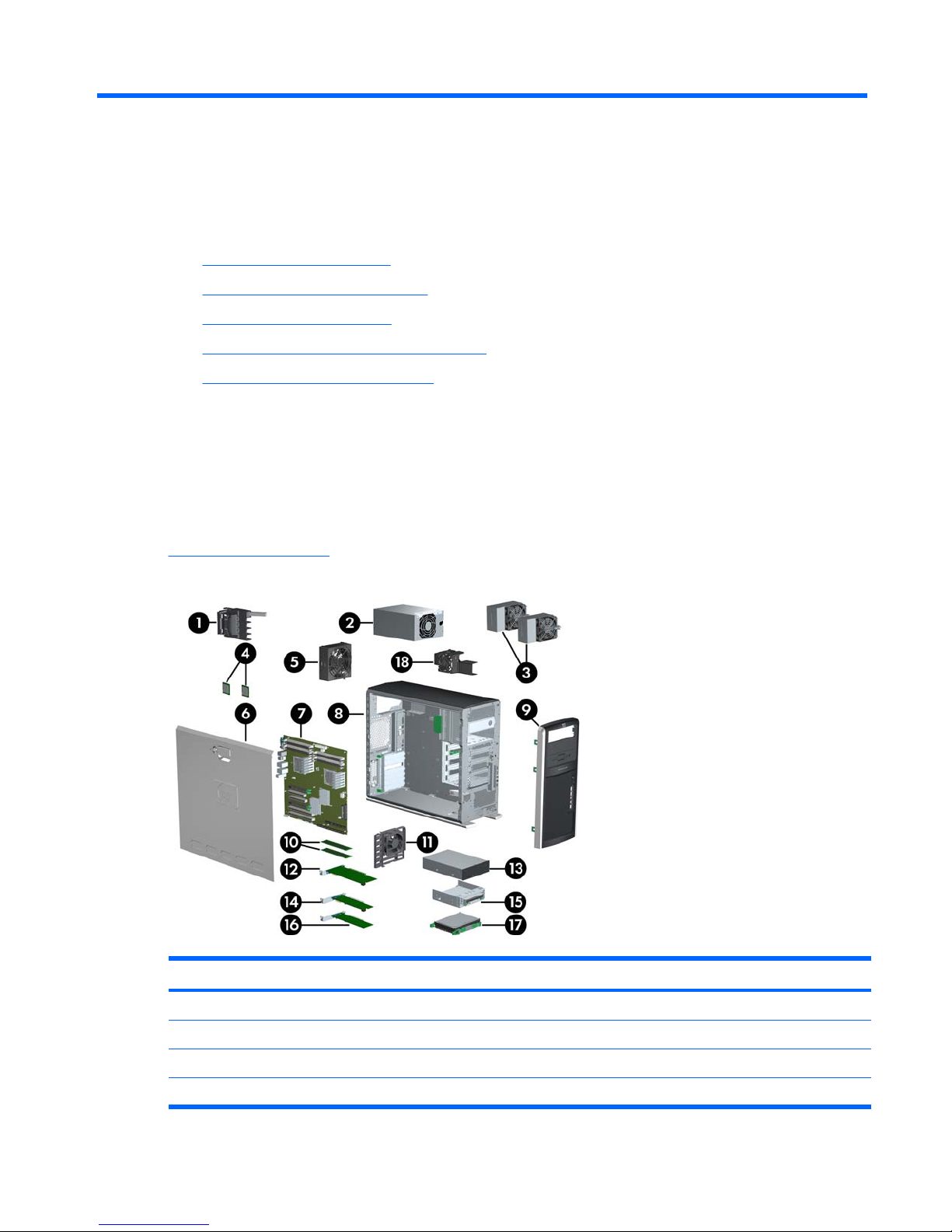
The following image shows a typical HP xw9400 Workstation (drive configurations can vary).
For complete and current information on supported accessories and components, see
http://partsurfer.hp.com.
Figure 1-1 Exploded view
Table 1-1 Exploded view
Item Description Item Description
1 PCI card support 10 Memory modules
2 Power supply 11 Card guide/Front fan
3 CPU heatsinks 12 Graphics card
4 Processors 13 Optical drive*
ENWW Product features 1
Page 12

Item Description Item Description
5 System fan 14 PCIe card
6 Access panel 15 Diskette drive
7 System board 16 PCI card
8 Chassis 17 Hard drive
9 Front bezel 18 Memory fan
* A CD-ROM is an example of an optical drive.
Table 1-1 Exploded view (continued)
2 Chapter 1 Product overview ENWW
Page 13
Front panel components
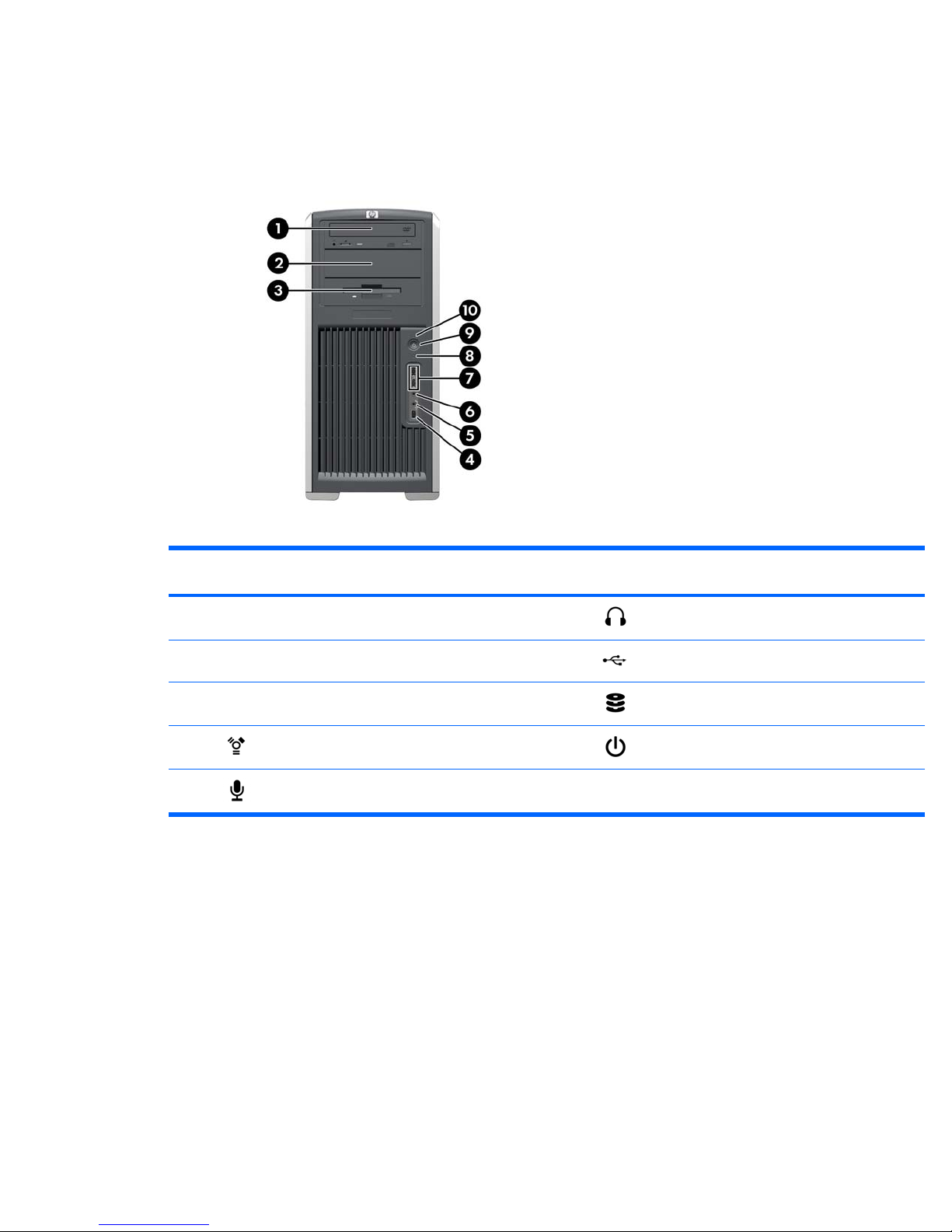
The following image shows a typical HP xw9400 Workstation. Drive configurations can vary.
Figure 1-2 Front panel components
Table 1-2 Front panel components
Item Symb
ol
Description Item Symb
ol
Description
1 Optical drive 6 Headphone connector
2 5.25-inch drive bay 7 USB 2.0 ports
3 Diskette drive (optional) 8 Hard drive activity light
4 IEEE-1394a connector 9 Power button
5 Microphone connector 10 Power on light
ENWW Product features 3
Page 14
Rear panel components
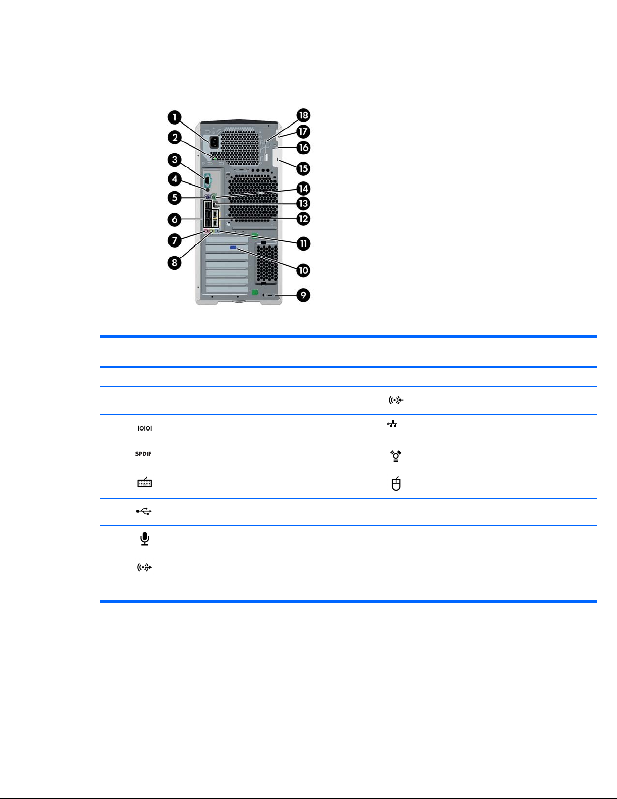
Figure 1-3 Rear panel components
Table 1-3 Rear panel components
Item Symbol
*
Description Item Symb
ol
Description
1 Power cord connector 10 Graphics adapter
2 Built In Self Test (BIST) LED 11 Audio line-in connector
3 Serial connector 12 RJ-45 network connectors
4 SPDIF OUT** 13 IEEE-1394a connector
5 Keyboard connector 14 Mouse connector
6 USB 2.0 ports 15 Cable lock slot
7 Microphone connector 16 Padlock loop
8 Audio line-out connector 17 Universal chassis clamp opening
9 MiniSAS 4–port connector (optional) 18 Access panel key
* The rear panel connectors are labeled with industry-standard icons and colors to assist you in connecting your peripheral
devices.
** SPDIF OUT is a single RCA jack to support SPDIF digital audio output via coax cable.
Serial number and COA label location
Each workstation has two unique serial number labels. Systems preinstalled with Microsoft® Windows®
XP also have a certificate of authentication (COA) label (2). The serial number labels (1) are located on
4 Chapter 1 Product overview ENWW
Page 15
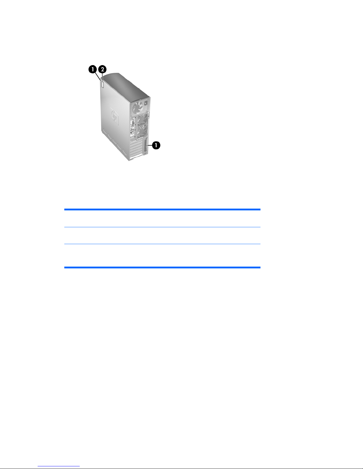
the side panel of the unit and on the rear panel. Keep the serial number available when contacting
customer service for assistance.
Figure 1-4 Serial number and COA label location
Product specifications
The following table lists the physical dimensions.
Table 1-4 Physical characteristics
Weight (depending on
configuration)
18-27.7 kg (39.6-61.1 lb.)
Tower dimensions 455 mm (17.9 in.) tall, 210 mm (8.3 in.) wide, 525
mm (20.7 in.) deep
Rack mount
dimensions (top cover
and foot removed)
210 mm (8.3 in.) tall, 440 mm (17.3 in.) wide, 525
mm (20.7 in.) deep
ENWW Product specifications 5
Page 16

Power supply and cooling
This section describes power supply specifications.
Table 1-5 Power supply source voltages
Source voltage Description
+3.3V PCI, PCIe, onboard logic, SAS controller, IEEE 1394, and
chipset
+5V Storage (disk, optical, diskette), PCI, audio, USB, input to
onboard regulator, and onboard logic
+12 V-CPU0 Input to onboard regulator that supplies power to CPU0 and
CPU0 fan
+12 V-CPU1 Input to onboard regulator that supplies power to CPU1,
CPU1 fan, and chipset regulators
+12 V-M Input to onboard regulator that supplies power to memory
+12 V-B PCI, PCIe, and system fans
+12 V-D Storage (hard drive, optical drive, diskette drive)
+12 V/G1 PCI Express auxiliary connector
+12 V-G2 Second PCI Express auxiliary connector
+12 V-R Not used
+12 V-N PCI and serial ports
+5 V-SB Sleep circuitry
Table 1-6 Maximum current per rail
Voltage rail 1050W maximum
continuous current
+3.3V 22.0A
+5V 18.0A
+12 V-CPU0 18.0A
+12 V-CPU1 18.0A
+12 V-M 18.0A
+12 V-B 18.0A
+12 V-D 18.0A
+12 V/G1 18.0A
+12 V-G2 18.0A
+12 V-R 18.0A
+12 V-N 0.30A
+5 V-SB 9.0A
6 Chapter 1 Product overview ENWW
Page 17

CAUTION: Do not exceed 150 watts of 3.3V and 5V power combination.
Do not exceed 84.0 amps (1008W) of 12V (CPU0/CPU1/M/B/D/G1/G2/R) power combination.
Do not exceed 1050 watts of total continuous output power.
ENWW Product specifications 7
Page 18

Power supply specifications
The integrated, surge-tolerant power supply is rated to withstand a power surge of up to 2,000 V (lineto-PE or neutral-to-PE) and 1,000 V (line-to-line) without any data loss or system downtime. The
following specifications describe the power supply:
Table 1-7 Power supply specifications
Item Description
Power supply 1050W
Wide Ranging, Active PFC
Operating voltage range 90-269 VAC
Rated voltage range 100-240 VAC 118 VAC
Rated line frequency 50-60 Hz 400 Hz
Operating line frequency
range
47-66 Hz 393-407 Hz
Rated input current 13.2A @ 100-127
VAC
6.6A @ 200-240
VAC
12.0A @ 118
VAC
Heat dissipation
(Configuration and
software dependent)
Typical 3,136 BTU/hr = 791kg-cal/hr)
Maximum 4,480 BTU/hr = 1,129 kgcal/hr)
Power supply fan 92x32 mm variable speed
80 Plus compliant 80 Plus compliant and compatible
with ENERGY STAR compliant
configurations.
FEMP Standby Power
compliant @115V (<2W in
S5 – Power Off)
No
Power Consumption in
ENERGY STAR Mode –
Suspend to RAM (S3)
(Instantly Available PC)
<25 watts
Built-in self-test LED Yes
Surge tolerant (withstands
power surges up to 2000V)
Yes
Power consumption and heat dissipation
Power consumption and heat dissipation specifications are available for multiple power supply
configurations. To review available specifications, see
http://www.hp.com/go/quickspecs.
To reach zero power consumption, unplug the workstation from the power outlet or use a power strip
with an on/off switch. For additional information about power-saving features, see your operating system
documentation.
This product is in compliance with U.S. Executive Order 13221.
8 Chapter 1 Product overview ENWW
Page 19

System fans and airflow
The workstation includes one rear system fan, one memory fan, one processor (CPU) heatsink fan for
each processor, and one power supply fan, plus a front system fan.
Resetting the power supply
If an overload triggers the power supply overload protection, all power is immediately shut off. To reset
the power supply unit:
1. Disconnect the power cord.
2. Determine what caused the overload and fix the problem.
3. Reconnect the power cord and reboot the workstation.
When you power down the workstation through the operating system, power consumption falls below
the low power consumption rate but does not reach zero. This on/off feature extends the life of the power
supply.
Power cord requirements
The power cord set (flexible cord or wall plug) received with this product meets the requirements for use
in the country where you purchased the equipment.
If you must obtain a power cord for a different country, you should purchase a power cord that is
approved for use in that country.
The power cord must be rated for the product and for the voltage and current marked on the product’s
electrical ratings label. The voltage and current rating of the cord should be greater than the voltage and
current rating marked on the product. The length of the cord must be between 1.8m (6 feet) and 3.6m
(12 feet). If you have questions about the type of power cord to use, contact the HP authorized service
provider.
A power cord should be routed so that it is not likely to be walked on or pinched by items placed on it
or against it. Particular attention should be paid to the plug, electrical outlet, and the point where the
cord exits from the product.
NOTE: A 15AMP-capable (minimum) power cord must be used in with a 110-V power source. A
10AMP-capable (minimum) power cord should be used with a 220-V power source.
ENWW Product specifications 9
Page 20

Environmental specifications
This section describes environmental specifications of your workstation.
Temperature
Operating: 5 to 35°C (40 to 95°F)
Non-operating: -40 to 60°C (-40 to 140°F)
NOTE: Derate by one degree C (1.4 degrees F) for every 305m
(1,000 ft.) altitude over 1,524m (5,000 ft.).
Humidity
Operating: 8 to 85% RH, non-condensing
Non-operating: 8 to 90% RH, non-condensing
Altitude
Operating: 0 to 3,048m (10,000 ft.)
Non-operating: 0 to 9,144m (30,000 ft.)
Shock
Operating: ½-sine: 40g, 2-3ms
Non-operating:
●
½-sine: 160 cm/s, 2-3ms (~100g)
●
square: 422 cm/s, 20g
NOTE: Values represent individual shock events and do not
indicate repetitive shock events.
Vibration
Operating random: 0.5g (rms), 5-300 Hz
Non-operating random: 2.0g (rms), 10-500 Hz
NOTE: Values do not indicate continuous vibration.
PCI card slot power specification
Table 1-8 PCI and PCI Express slot power specifications
Slot# Slot Type Slot Power (Maximum)
1 PCI Express x16 (x8) 25W*
2 PCI Express x16 graphics 150W**
3 PCI 32 bit, 33 MHz 25W*
4 PCI Express x16 (x8) 25W*
5 PCI Express x16 graphics 150W**
6 PCI-X 100 25W*
7 PCI-X 100/133 25W*
* In addition to these slot power specifications, the overall power consumption of the system (including I/O cards, processor,
and memory) must not exceed the maximum ratings of the system power supply. See
Power supply specifications
on page 8 for details.
** Includes 75 W maximum from the system board connector, and 75 W maximum from the auxiliary graphics power connector.
10 Chapter 1 Product overview ENWW
Page 21

NOTE: If a graphics card requiring more than 75W is installed in Slot 2, HP recommends not using
slot 3, which is the PCI slot below the graphics slot. If a graphics card requiring more than 75W is installed
in slot 5, HP recommends not using slot 6, which is the PCI-X 100 slot below the graphics slot. In addition
to these slot power specifications, the overall power consumption of the system (including I/O cards,
processors, memory, and drives) must not exceed the maximum ratings of the system power supply.
Also, there are broad restrictions on using dual 150W graphics cards.
For hardware specifications of other system components, such as graphics cards or optical drives, see
the website of the specific manufacturer.
Chipkill support
Chipkill is a form of advanced Error Checking and Correcting (ECC) computer memory technology. The
HP xw9400 Workstation supports 128-bit Chipkill ECC memory functionality. Standard ECC functionality
detects and corrects single bit data errors in memory systems. But Chipkill offers greater memory error
protection by providing error correction for up to 4-bit errors within the same symbol (nibble boundary).
Chipkill cannot correct any random four bits across 128 bits.
Chipkill on the xw9400 functions within these parameters:
●
The workstation enables Chipkill functionality on paired ECC memory DIMMs only.
●
The use of single memory DIMM—not supported on the xw9400 workstation—allows standard
single bit ECC only.
●
Chipkill can detect and correct up to four bit errors if the four bits are in the same symbol. That is,
multiple bit errors in bits 0–3 or 4–7 of a byte can be detected and corrected. Multi-bit error that
overlap or span symbol boundaries (bits 2–5 or 3–6, for example) cannot be corrected. For DIMMs
that are based on x4 parts, this means that a single DRAM chip can fail and the system will continue
to operate. For x8 and x16 parts, a complete DRAM chip cannot fail, but symbol errors will be
corrected as described.
ENERGY STAR Qualification
HP computers marked with the ENERGY STAR logo are compliant with the applicable U.S.
Environmental Protection Agency (EPA) ENERGY STAR specifications for computers. The EPA
ENERGY STAR logo does not imply endorsement by the EPA. As an ENERGY STAR Partner, HewlettPackard Company has determined the products marked with the ENERGY STAR logo are ENERGY
STAR qualified per the applicable ENERGY STAR guidelines for energy efficiency. The following logo
appears on all ENERGY STAR qualified computers.
The ENERGY STAR Computers Program was created by the EPA to promote energy efficiency and
reduce air pollution through more energy-efficient equipment in homes, offices, and factories. One way
products achieve this energy efficiency is by reducing power consumption when not being used through
the Microsoft Windows Power Management feature.
The Power Management feature enables the workstation to enter a low-power (or “sleep”) mode after
a period of inactivity. When used with an external monitor that is ENERGY STAR qualified, this feature
also supports the similar power management features of the external monitor.
ENWW Chipkill support 11
Page 22

To take advantage of this energy savings:
●
The Power Management feature has been preset to suspend the workstation to a sleep state after
30 minutes of inactivity.
●
The Power Management feature has been preset to suspend the monitor to a sleep state after 15
minutes of inactivity.
Both the computer and monitor can be woken from sleep mode through user interaction with any of the
computer input devices (mouse, keyboard, and so on). when configured with Wake On LAN (WOL)
enabled, the workstation can also be woken by a network signal.
See the EPA ENERGY STAR Power Management Web site for more information about the energy and
financial savings potential of the Power Management Feature:
http://www.energystar.gov/
powermanagement.
See the EPA ENERGY STAR Web site for more information about the ENERGY STAR program and
its environmental benefits:
http://www.energystar.gov.
CAUTION: Using the Energy Save Monitor feature with monitors that are not ENERGY STAR qualified
can cause video distortion when an Energy Save timeout occurs.
NOTE: ENERGY STAR is not supported on Linux workstations.
If it is necessary to restore the operating system, you must also reset the ENERGY STAR settings (if
applicable) after the restore.
To verify the factory default power settings for your workstation, select Start>Control Panel, and then
double-click Power Options.
Multi-core processors
This HP Workstation supports selected AMD Opteron™ 2000 series multi-core processors that provide
multiple true processors in a single socket. Multi-core processors are better at handling the load of multithreaded applications (such as rendering images in Digital Content Creation) and highly multi-tasked
environments (such as running several productivity applications while listening to music).
12 Chapter 1 Product overview ENWW
Page 23

2 Setting up the operating system
This chapter provides setup and update information for the workstation operating system. It includes
these topics:
Topics
Setting up the Microsoft operating system on page 14
Setting up Red Hat Enterprise Linux on page 15
Setting up Novell SLED on page 16
Updating the workstation on page 16
This chapter also includes information on how to determine that you have the latest BIOS, drivers, and
software updates installed on the workstation.
CAUTION: Do not add optional hardware or third-party devices to the HP workstation until the
operating system is successfully installed. Adding hardware might cause errors and prevent the
operating system from installing correctly.
ENWW 13
Page 24

Setting up the Microsoft operating system
NOTE: If you ordered a downgrade from Windows Vista to Windows XP Professional operating
system, your system will be preinstalled with Windows XP Professional operating system. With this
configuration, you will receive recovery media for Windows Vista operating system only. In case you
need to restore or recover the Windows XP Professional operating system in the future, it is important
that you create recovery media disks for Windows XP Professional operating system after first boot.
When you first apply power to the workstation, the operating system is installed. This process takes
approximately 5 to 10 minutes. Carefully follow the instructions on the screen to complete the installation.
CAUTION: After installation has started, do not turn off the workstation until the process is complete.
Turning off the workstation during installation can damage the installation and operation of the software.
For complete operating system installation and configuration instructions, see the operating system
documentation that was provided with the workstation. Additional information is available in the online
help tool after you successfully install the operating system.
Installing or upgrading device drivers
To install hardware devices after the operating system is installed, you must install the appropriate
device drivers before you install the devices. Follow the installation instructions that came with the
device. In addition, for optimum performance, your operating system must have the most recent updates,
patches, and software fixes. For additional driver and software update information, refer to
Upgrading
device drivers on page 18.
Transferring files and settings to your Windows workstation
The Microsoft Windows operating system offers data migration tools that helps you choose and transfer
files and data from a Windows computer to your Windows Vista or Windows XP Professional operating
system workstation.
For instructions on how to use these tools, see the documents at
http://www.microsoft.com.
14 Chapter 2 Setting up the operating system ENWW
Page 25

Setting up Red Hat Enterprise Linux
HP offers an HP Installer Kit for Linux (HPIKL) to supplement Red Hat box sets and help HP Linux
customers customize their system image. The HPIKL contains the HP driver CD and device drivers to
successfully setup up the Red Hat Enterprise Linux (RHEL) operating system, The HP Installer Kit for
Linux CDs are currently available for download at
http://www.hp.com/support/workstation_swdrivers.
Installing with the HP driver CD
To install the HP driver CD, see “Installing with the HP Installer Kit for Linux” in the HP Workstations for
Linux manual at
http://www.hp.com/support/workstation_manuals.
ENWW Setting up Red Hat Enterprise Linux 15
Page 26

Installing and customizing Red Hat-enabled workstations
Linux-enabled workstations require the HP Installer Kit and the purchase of a Red Hat Enterprise Linux
box set. The Installer kit includes the HP CDs necessary to complete the installation of all versions of
the Red Hat Enterprise Linux box set that have been qualified to work on an HP workstation.
To use the drivers in the HP Installer kit for Linux other than RHEL, you must manually extract the drivers
from the HP Driver CD and install them. HP does not test the installation of these drivers on other Linux
distributions nor does HP support this operation.
Verifying hardware compatibility
To see which Linux versions have been qualified to work on HP Workstations visit http://www.hp.com/
support/linux_hardware_matrix.
Setting up Novell SLED
To set up the SUSE Linux Enterprise Desktop (SLED) on systems preloaded with the operating system:
1. Boot the workstation.
2. Start the Installation Settings and enter the password, network, graphics, time, keyboard settings,
and Novell Customer Center Configuration for the workstation.
NOTE: During Installation Settings after the first time after booting the system the Novell
subscription can be activated from the Novell Customer Center Configuration screen. Visit the full
Novell Customer Center documentation at
http://www.novell.com/documentation/ncc/.
Updating the workstation
HP is constantly working on improving your total workstation experience. To ensure that the workstation
leverages the latest enhancements, HP recommends that you install the latest BIOS, driver, and
software updates on a regular basis.
Updating the workstation after first boot
After successfully booting the workstation for the first time, you should follow these guidelines to ensure
that the workstation is up-to-date:
●
Ensure that you have the latest system BIOS loaded. See
Upgrading the BIOS on page 16 for
instructions.
●
Ensure that you have the latest drivers for your system. See
Upgrading device drivers
on page 18 for instructions.
●
Become familiar with your available HP resources.
●
Consider a subscription to Driver Alerts at
http://www.hp.com/go/subscriberschoice.
Upgrading the BIOS
For optimum performance, determine the BIOS revision on the workstation, and upgrade it if necessary.
16 Chapter 2 Setting up the operating system ENWW
Page 27

Determining current BIOS
To determine the current BIOS of the workstation during system power up:
1. Wait for F10=setup to appear on the lower right corner of the screen.
2. Press F10 to enter the F10 Setup utility.
The F10 Setup utility displays the workstation BIOS version under File > System Information.
3. Note the workstation BIOS version so that you can compare it with the BIOS versions that appear
on the HP website.
ENWW Updating the workstation 17
Page 28

Upgrading BIOS
To find and download the latest available BIOS, which includes the latest enhancements:
1. Go to
http://www.hp.com/go/workstationsupport.
2. Select Download Drivers and Software from the left menu column under Tasks.
3. Follow the instructions to locate the latest BIOS available for the workstation.
4. If the BIOS on the Web site is the same as the version on your system, no further action is required.
5. If the BIOS on the Web site is a version later than the one on your system, download the appropriate
version for the workstation. Follow the instructions in the release notes to complete the installation.
Upgrading device drivers
If you install a peripheral device (such as a printer, display adapter, or network adapter), confirm you
have the latest device drivers loaded. If you purchased your device through HP, visit the HP Web site
to download the latest drivers for your device. These drivers have been tested to ensure the best
compatibility between your device and your HP workstation.
If you did not purchase your device from HP, HP recommends visiting the HP Web site first to see if
your device and its drivers have been tested for HP workstation compatibility. If no driver is available,
visit the device manufacturer's Web site to download the latest drivers.
To upgrade device drivers:
1. Go to
http://www.hp.com/go/workstationsupport.
2. Select Download Drivers and Software from the left menu column under Tasks.
3. Follow the instructions to find the latest drivers available for the workstation.
If a needed driver is not found, see the Web site of the manufacturer of the peripheral device.
18 Chapter 2 Setting up the operating system ENWW
Page 29

3 Restoring the operating system
This chapter describes how to restore the Windows or Linux operating system. It includes these topics:
Topics
Restore methods on page 19
Ordering backup software on page 20
Restoring Windows Vista on page 20
Restoring Windows XP Professional on page 21
Restoring Novell SLED on page 23
Installing with the HP driver CD on page 15
Restore methods
The Windows Business Vista operating system can be reinstalled using the HP RestorePlus! process.
The Windows XP Professional operating system can be reinstalled using the RestorePlus! process or
the HP Backup and Recovery Manager.
●
RestorePlus!
The RestorePlus! process reinstalls the Windows operating system and device drivers (for devices
included with the system) to a near-factory state. The process does not back up or recover data
on the hard drive. Some application software might not be restored using this process and must
be installed from the appropriate application CD.
●
HP Backup and Recovery Manager (HPBR) Recovery Point
The HP Backup and Recovery Manager application can be used to capture and restore the contents
of the system partition. It captures a snapshot of the system partition and stores it in a Recovery
Point. Everything on the system partition at the time the recovery point was made is saved.
NOTE: HP Backup and Restore is only supported on the HP xw6600 and xw8600 Workstations.
The Recovery Point is saved to the hard drive and can be burned to media for safekeeping.
CAUTION: These methods restore the operating system, but not data. Data must be backed up
regularly to avoid loss.
ENWW Restore methods 19
Page 30

Ordering backup software
If you cannot create system recovery CDs or DVDs, you can order a recovery disk set from the HP
support center. To obtain the support center telephone number for your region visit
http://www.hp.com/
support/contactHP.
Restoring Windows Vista
This section describes how to restore Windows Vista.
Ordering the RestorePlus! media
If you ordered restore media with your workstation, the media is included with your workstation
components.
If you did not order restore media, call HP Support and request a RestorePlus! media kit. For worldwide
technical support phone numbers, visit
http://www.hp.com/support.
Restoring the operating system
NOTE: Windows Vista provides a backup and restore application as well. To learn more about this
application, visit the Microsoft Web site.
CAUTION: Before you restore the operating system, back up your data.
When you run RestorePlus! from media, the process deletes all information on the primary hard drive,
including all partitions.
To restore Windows Vista:
1. Boot from the RestorePlus! DVD to start the RestorePlus! process. You must start from the
RestorePlus! DVD to install device drivers and settings.
2. Follow the prompts to restore your operating system.
Some application software might not be restored using this process. If software is not restored, install
it from the appropriate application DVD.
20 Chapter 3 Restoring the operating system ENWW
Page 31

Restoring Windows XP Professional
This section describes how to restore the Windows XP Professional operating system.
NOTE: The workstation must have a CD or DVD writer installed to create the media set.
Creating RestorePlus! media
The RestorePlus! kit can be created using the files contained on the hard drive. To create the restore
media:
1. Boot the workstation.
2. During boot up, an HP Backup and Recovery Manager screen is displayed prompting you to create
Recovery CDs or DVDs. Select Now.
3. An Initial Recovery Point (IRP) of the system is captured. This is a snapshot of the system hard
drive. The capture can take more than 10 minutes.
4. After the IRP is created, you can create a set of backup CDs or DVDs.
To create a RestorePlus! media set including the Windows XP operating system CD, select
RestorePlus! > Microsoft Windows XP operating system > Supplemental media.
NOTE: Depending on the options, there might be additional DVDs you can create.
5. Follow the prompts to create RestorePlus!, operating system, and HPBR media.
If you are unable to create CD/DVDs on your workstation, call HP Support and request a RestorePlus!
media kit. For worldwide technical support phone numbers, visit
http://www.hp.com/support.
ENWW Restoring Windows XP Professional 21
Page 32

Creating HP Backup and Recovery (HPBR) media
NOTE: HPBR functionality is used with Windows XP only. For details, refer to the SoftThinks guide
on the Documentation and Diagnostics CD included with the workstation.
The Initial Recovery Point can be burned to optical media and used to recover a system. This section
describes making the media.
NOTE: The workstation must have a CD or DVD writer to create the media set.
To create HPBR recovery media:
1. The Initial Recovery Point was captured when the RestorePlus! media set was created previously.
If the IRP was not created, start the HP Backup and Recovery Manager and create recovery points
using the Expert mode. Follow the HPBR online documentation for instructions.
2. Burn the IRP to media from HPBR.
Select HPBR Start > All Programs > HP Backup & Recovery > HP Backup and Recovery
Manager.
3. Select Next at the first screen.
Select Create recovery CDs or DVDs to recover the system, and then select Next.
4. Choose Next to display a list of available CD image and the recovery points.
5. Check the box next to Initial Recovery Point, and then select Next.
6. Follow the instructions to create the media.
22 Chapter 3 Restoring the operating system ENWW
Page 33

Restoring the operating system
CAUTION: Before you restore the operating system, back up your data.
When you run RestorePlus! from media, the process deletes all information on the primary hard drive,
including all partitions. If you run RestorePlus! from the recovery partition, only the root (C:) partition is
affected.
Using RestorePlus!
To restore with RestorePlus!:
1. Boot the workstation from the RestorePlus! DVD. You must start from the RestorePlus! DVD for
device drivers and settings to be installed.
2. Follow the prompts to restore the operating system.
Some application software might not be restored using this process. If software is not restored, install
it from the appropriate application DVD.
Using HPBR
To restore with the HPBR Initial Recovery Point media:
1. Boot the workstation from the Initial Recovery Point media.
2. Follow the prompts to restore the system to the state when the IRP was created.
Using the recovery partition
A system that shipped with Windows XP includes a recovery partition. You can boot the system from
that recovery partition.
From the recovery partition you can perform a system restore using the HPBR Initial Recovery Point, if
it was created. If it was not, you can use a RestorePlus! install.
To restore using the recovery partition:
1. Boot the workstation.
2. When prompted on the boot screen to enter the Recovery Manager, press F11.
TIP: The opportunity to press F11 during the boot process is small. It comes about the time the
F10 prompt appears.
NOTE: To ensure that the recovery processes reinstall on the correct hard drive, do not
disconnect the target drive during the recovery process.
3. Follow the prompts to restore the system to factory-like condition.
Restoring Novell SLED
The SLED restore media is required to restore the Linux operating system.
Creating restore media
THE SUSE Linux Enterprise Desktop preload includes a SUSE ISO icon on the desktop. You can click
this icon to go to the /iso directory. The /iso directory contains all iso images used to preload your
workstation. To recover or restore the original image, follow the instructions in the readme file in the /
iso directory to copy the ISO image file onto CDs.
ENWW Restoring Novell SLED 23
Page 34

NOTE: Make copies of the ISO recovery images on CD as backup files in case your workstation
experiences a hard drive failure.
24 Chapter 3 Restoring the operating system ENWW
Page 35

4 System management
This section describes the various tools and utilities that allow for the system management of the
workstation.
●
Computer Setup (F10) Utility on page 25
●
Desktop management on page 36
Computer Setup (F10) Utility
The Computer Setup Utility enables you to:
●
Change current settings from the factory default settings.
●
Modify or restore factory default settings.
●
Determine if all of the devices installed on the workstation are recognized by the system and
functioning properly.
●
Determine information about the operating environment of the workstation.
●
Solve system configuration errors detected but not automatically fixed during the Power-On SelfTest (POST).
●
Establish and manage security features and password prompting during system reset and during
power-on.
●
Establish and manage energy-saving time-outs (not supported for Linux platforms).
●
Set the system date and time.
●
Set, view, and change the system configuration, including settings for processor, graphics,
memory, audio, storage, communications, and input devices.
●
Modify the boot order of installed mass storage devices such as hard drives, diskette drives, optical
drives, and network drives.
●
Enable or disable Network Server Mode, which enables the workstation to boot the operating
system when the power-on password is enabled with or without a keyboard or mouse attached.
When attached to the system, the keyboard and mouse remain locked until the power-on password
is entered.
●
Enable/disable POST Messages to change the display status of POST messages. POST
messages disabled suppresses most POST messages, such as memory count, product name, and
other non-error text messages. If a POST error occurs, the error is displayed regardless of the
mode selected. To temporarily switch to POST messages enabled, press any key (except F1
through F12) during POST.
●
Establish an Ownership Tag, the text of which is displayed each time the system is turned on or
restarted.
●
Enter the Asset Tag or property identification number assigned by your company to this
workstation.
ENWW Computer Setup (F10) Utility 25
Page 36

●
Secure the integrated I/O functionality, including the serial and USB ports, audio, embedded NIC,
SAS, or IEEE 1394 so that the I/O functionality cannot be used until they are unsecured.
●
Enable or disable removable media boot ability.
●
Enable or disable removable media write ability (when supported by hardware). Used commonly
for legacy diskettes.
●
Replicate your system setup by saving system configuration information onto diskette or USB, or
restoring it onto one or more workstations.
BIOS ROM
The BIOS of the computer is a collection of programs stored as firmware in ROM. The BIOS ROM
includes such functions as POST, PCI device initialization, Plug 'n' Play support, power management
activities, and the Computer Setup Utility. BIOS supports the following systems and specifications:
●
Dual AMD Opteron 2xxx series processors
●
Up to DDR2-667 memory
●
HyperTransport setup and initialization
●
Chipset (includes NVIDIA nForce Professional 3600 and 3050 with NEC ?PD720404 PCIe to PCIX bridge)
●
ACPI 1.0b with ACPI 2.0 extensions for 64-bit support, according to Microsoft Logo Requirements.
S1, S3, S4, and S5 with Remote Power On by way of LAN wake packet.
●
SMBIOS Spec 2.5 implementation and field definitions that accurately represent hardware
configurations and OEM ID
●
BBS 1.01
●
DOS and Windows based BIOS flash tools
●
Microsoft SDG 3.0 compliant as applicable
●
PMM 1.01 as applicable
●
MPS 1.4 as applicable
●
PXE 2.1
●
USB 1.1/USB 2.0
●
PCI 2.2 or later
●
“El Torito” Bootable CD 1.0
The BIOS ROM is a 1-MB FLASH unit. The runtime portion of the BIOS resides in a 96-KB block from
E8000h to FFFFFh (approximately). ACPI code and data take about 128 KB below TOLM (top of low
memory, the last RAM address below 4 GB).
26 Chapter 4 System management ENWW
Page 37

Using Computer Setup (F10) Utility
You can call up the Computer Setup Utility during workstation restart or power on. To access the
Computer Setup Utility menu:
1. Power on or restart the workstation.
2. Press the F10 key as soon as your display is active and the message Setup appears in the lower
right corner of the screen.
NOTE: If you miss the opportunity to press F10, restart the workstation and press F10 again. Or,
you can press Ctrl+Alt+Delete prior to boot .
3. At first boot, select your language from the list, and press the Enter key. In the Computer Setup
Utility menu, five headings are displayed: File, Storage, Security, Advanced, and I/O.
4. Use the left and right arrow keys to select the appropriate heading. Use the up and down arrow
keys to select the option you want, and press Enter.
5. To apply and save changes, select File>Save Changes and Exit.
●
If you have made changes that you do not want applied, select File>Ignore Changes and
Exit.
●
To reset to factory settings, select File>Default Setup>Restore Factory Settings as
Default. Press F10 to accept the changes. Click File>Apply Defaults and Exit. This option
restores the original factory system defaults.
CAUTION: Do not turn the workstation power off while the ROM is saving your Computer Setup Utility
changes because the CMOS could become corrupted. After you exit the F10 Setup screen, it is safe to
remove all power from the workstation.
ENWW Computer Setup (F10) Utility 27
Page 38

Computer Setup (F10) Utility menu
NOTE: The following content is subject to change with new BIOS releases, so your menu may be
different than shown in Table 1–1.
Table 4-1 Computer Setup Utility menu descriptions
Heading Option Description
File System
Information
Lists product name, SKU number, processor type/speed/stepping, cache size
(L1/L2), memory type and size, integrated Media Access Control (MAC) IDs for
Network Interface, system BIOS type, chassis serial number, asset tracking
number, and Boot Block Date.
About Displays copyright information.
System
Temperatur
es
Displays temperature graph.
Set Time
and Date
Enables you to set system time and date.
Flash
System
ROM
Enables you to select a device from which to flash system ROM.
Replicated
Setup
Save to Removable Media
Saves the current F10 Setup configuration to a text file called
cpqsetup.txt.
Restore from Removable Media
Restores previous F10 Setup configuration from a text file called
cpqsetup.txt.
Default
Setup
Save Current Settings as Default
Stores the current F10 Setup configuration as the default.
Restore Factory Settings as Default
Restores the original factory settings to the F10 Setup configuration information
as the default.
Apply
Defaults
and Exit
Saves the selected default settings (previously-saved user or factory settings)
and exits the Computer Setup Utility.
Ignore
Changes
and Exit
Exits the Computer Setup Utility without applying or saving any changes.
Save
Changes
and Exit
Saves changes to system configuration and exits the Computer Setup Utility.
Storage Device
Configuratio
n
Lists all installed non-SAS and non-SATA storage devices.
When a device is selected, detailed information and options are displayed.
28 Chapter 4 System management ENWW
Page 39

Heading Option Description
Hard Disk
Identifies the hard disk drives on the system by model, firmware, serial number,
connector color, emulation type, multisector transfers, and translation mode.
By default, SATA drives are not listed here.
Default values can be set here for IDE and SATA drives, but not for SAS drives.
CD-ROM
Identifies the optical drives on the system.
Diskette (for legacy diskette drives only)
Identifies the highest capacity media type accepted by the diskette drive.
Options are 3.5" 1.44 MB, 5.25" 1.2 MB, and Not Installed.
Default Values
Enables you to set the default values for IDE and SATA devices such as the
following:
●
Multisector Transfers (IDE devices only)–Specifies how many sectors are
transferred per multi-sector Programmed Input/Output (PIO) operation.
Options (subject to device capabilities) are Disabled, 8, and 16.
●
Transfer Mode (IDE devices only)–Specifies the active data transfer mode.
Options (subject to device capabilities) are PIO 0, Max PIO, Enhanced
DMA, Ultra DMA 0, and Max UDMA.
●
Translation Mode (IDE/SATA disks only)–Enables you to select the
translation mode to be used for the device, which enables the BIOS to
access disks partitioned and formatted on other systems and may be
necessary for users of older versions of UNIX (for example, SCO UNIX
version 3.2). Options are Bit-Shift, LBA Assisted, Off, User, and Automatic.
NOTE: The Automatic option allows BIOS to automatically determine the
translation mode used to configure a previously-formatted IDE, SATA, or
USB mass storage device. Hence, you do not have to know how the mass
storage device was previously formatted.
Ordinarily, the translation mode selected automatically by the BIOS should
not be changed. If the selected translation mode is not compatible with the
translation mode that was active when the disk was partitioned and
formatted, the data on the disk will be inaccessible.
Storage
Options
Removable Media Boot
Enables/disables ability to boot the system from removable media.
Legacy Diskette Write
Enables/disables ability to write data to legacy media.
BIOS DMA Data Transfers
Enables/disables DMA transfers for IDE and SATA devices when possible
during POST to increase transfer speed.
SATA Controller #0
Enables/disables SATA controller 0.
SATA Controller #1
Enables/disables SATA controller 1.
Table 4-1 Computer Setup Utility menu descriptions (continued)
ENWW Computer Setup (F10) Utility 29
Page 40

Heading Option Description
SATA Controller #2
Enables/disables SATA controller 2.
IDE Controller
Enables/disables IDE controller.
Boot Order Enables you to configure the boot, diskette drive, and hard drive orders by
physically reordering the menu entries. Each device on the list can be
individually excluded from or included for consideration as a bootable operating
system source. Boot Order presents these selections:
●
Optical drive
●
Diskette drive
●
USB device
●
Hard drive
●
Network controllers (2)
Boot devices can be disabled from participating in the boot order process. Boot
order changes are stored when the F10 Setup changes are confirmed by
selecting File>Save Changes and Exit.
NOTE: MS-DOS drive lettering assignments might not apply after a non-MS-
DOS operating system has started.
Shortcut to Temporarily Override Boot Order
To boot one time from a device other than the default device specified in Boot
Order, restart the workstation and press the F9 key when the F9=Boot Menu
message appears on the screen. After POST is completed, a list of bootable
devices is displayed. Use the arrow keys to select the preferred bootable device
and press Enter. The workstation then boots from the selected device for this
one time.
Security Setup
Password
Enables you to set and enable setup (administrator) password.
NOTE: If the setup password is set, you must enter Computer Setup Utility
to change it, flash the ROM, and make changes to certain plug-and-play
settings under Windows.
Power-On
Password
Enables you to set and enable the power-on password.
NOTE: If a power on-password is set, or the workstation cover removal
sensor is activated, entries for these items will appear in this list.
Table 4-1 Computer Setup Utility menu descriptions (continued)
30 Chapter 4 System management ENWW
Page 41

Heading Option Description
Device
Security
Makes the following devices available or hidden to the system:
●
Serial Port
●
All USB Ports
●
External USB ports
●
Front USB Ports
●
System Audio
●
IEEE 1394 Controller
●
Network Controller 1
●
Network Controller 2
●
Onboard SAS Controller
●
Embedded Security Device
For each device, Device Available is the default setting and allows the operating
system access to the device. Device hidden makes the device unavailable; it
is disabled by the BIOS and cannot be enabled by the operating system.
When enabled, Embedded Security Device offers these options:
●
Enable/disable—Turns the TPM on/off.
●
Power-On Authentication Support—Enables/disables an authentication
feature that requires you to enter a TPM user key password to boot the
system. This feature uses the TPM to generate and store the authentication
password.
●
Reset Authentication Credential—Resets the authentication functionality
and clears all authentication credentials.
NOTE: A setup password must be set to enable the Embedded Security
Device and to access any security features associated with the Embedded
Security Device.
Network
Service
Boot
Enables/disables a Network Service Boot which boots using the NIC PXE
option ROM. In this case, the actual boot image resides on a remote server.
When enabled, you can set the boot order of the NIC PXE option ROM and you
can force a network boot by pressing F12 during POST.
System IDs Asset Tag
A 16–byte string identifying the system.
Ownership Tag
An 80–byte string identifying ownership of the system. This tag is displayed on
the screen during POST.
UUID (Universal Unique Identifier)
Can only be updated if the current chassis serial number is invalid. (These ID
numbers are normally set in the factory and are used to uniquely identify the
system.)
Keyboard
Enables you to set the keyboard locale for System ID entry.
Table 4-1 Computer Setup Utility menu descriptions (continued)
ENWW Computer Setup (F10) Utility 31
Page 42

Heading Option Description
OS Security Data Execution Prevention
Enables/disables Data Execution Prevention mode in the processors. This
mode prohibits code from running in pages that were set up as data pages, and
prevents attacks such as buffer overflows. Operating system support is
required for this feature.
AMD Virtualization Technology
Enables AMD Virtualization Technology to increase workstation performance.
OS Management of Embedded Security Device
Enables/disables the ability of the operating system to control the TPM device.
This includes turning it on/off, initializing it, and resetting it.
Reset of Embedded Security Device through OS
Enables/disables the ability of the operating system to reset the TPM.
Advanced** Power-On
Options
Allows you to set:
●
POST Mode (QuickBoot, FullBoot, or FullBoot every 1–30 days).
●
POST Messages (Enable/Disable).
●
F9 Prompt (Enable/Disable). Enabling this feature will display the text
F9=Boot Menu during POST. Disabling this feature prevents the text from
being displayed. However, pressing the F9 key will still access the boot
menu.
●
F10 Prompt (Enable/Disable). Enabling this feature displays the text
F10=Setup during POST. Disabling this feature prevents the text from
being displayed but pressing F10 still accesses the Setup screen.
●
F11 Prompt (Enable/Disable). Makes the Factory Recovery option visible
during POST.
●
F12 Prompt (Enable/Disable). Enabling this feature displays the text
F12=Network Service Boot during POST. Disabling this feature prevents
the text from being displayed but pressing F12 still forces the system to
attempt booting from the network.
●
Factory Recovery Boot Support (Enable/Disable). Recovery partition
(HDD) option available for Vista. Vista leaves the factory with this support
in place.
●
Option ROM* prompt (Enable/Disable). Enabling this feature causes the
system to display a message before loading options ROMs.
●
Remote Wakeup Boot Source
●
After Power Loss (on/off)
●
POST Delay (in seconds) (Enable/Disable). Enabling this feature adds a
user-specified delay to the POST process. This delay is sometimes needed
for hard disks on some PCI cards that spin up slowly—so slowly that they
are not ready to boot by the time POST is finished. The POST delay also
gives you more time to select F10 to enter Computer Setup (F10).
●
I/O APIC Mode (Enable/Disable)
●
Limit (PUID Maximum Value to 3) (Enable/Disable)
●
Setup Browse Mode (Enable/Disable)
●
ACPI/USB Buffers @ Top of Memory (Enable/Disable)
Table 4-1 Computer Setup Utility menu descriptions (continued)
32 Chapter 4 System management ENWW
Page 43

Heading Option Description
POST Messages (Enable/Disable).
When enabled, POST displays non-error messages to the screen.
F9 Prompt (Displayed/Hidden)
Displays F9=Boot Menu during POST. Hiding this feature prevents the text
from being displayed, but pressing F9 still calls up the boot menu.
F10 prompt (Displayed/Hidden)
Displays F10=Setup during POST. Hiding this feature prevents the text from
being displayed but pressing F10 still accesses the Setup screen.
F12 prompt (Displayed/Hidden)
Displays F12=Network Service Boot during POST. Hiding this feature
prevents the text from being displayed, but pressing F12 still forces the system
to attempt booting from the network.
Option ROM* Prompt (Enable/Disable)
When enabled, causes the system to display a message before loading options
ROMs.
Remote Wakeup Boot Source
Enables you to specify which boot device to use after a remote wake event.
After Power Loss (Off/On/Previous State)
In the event of an AC power loss, determines system behavior when power is
restored. Options are Off (stay off), On (turn on immediately), and Previous
State (if the computer was on when power was lost, power on immediately; if
it was off, stay off).
POST Delay (in seconds) (None, 5, 10, 15, 20)
Specifies a delay during POST. This setting may be necessary for certain addin peripherals that respond slowly or violate specifications. For instance, disk
drives should spin up within 15 seconds, but some older drives might take
longer.
Setup Browse Mode (Enable/Disable)
Enables viewing Setup Options without entering Setup password. Enable
allows you to view Setup in read-only mode if you do not enter the Setup
password. Disable blocks Setup entirely if you do not enter the Setup
password. This option is only valid if a Setup password is set.
Thermal Fan Idle Mode
This setting changes the minimum fan speed. The fans are still automatically
controlled.
The internal fans of the system are controlled automatically to guarantee proper
operation of any configuration shipped from the factory. However, some
customers with cards and configurations with special thermal/cooling needs
may need to increase the minimum spinning speed of the fans in the system.
They can do so by using this menu and selecting a higher minimal fan speed.
BIOS
Power-On
Enables you to disable or specify a day and time for BIOS power-on.
OS Power
Manageme
nt
ACPI S3 Support (Enable/Disable)
Enables/disables ACPI S3 suspend-to-RAM (Standby) from OS.
Table 4-1 Computer Setup Utility menu descriptions (continued)
ENWW Computer Setup (F10) Utility 33
Page 44

Heading Option Description
ACPI S3 Hard Disk Reset (Enable/Disable)
When awakening from the ACPI S3 state, reset IDE hard drive before returning
to the OS.
ACPI S3 PS2 Mouse Wake Up (Enable/Disable)
Allow the mouse to awaken the system from the ACPI S3 state.
USB Wake on Device Insertion (Enable/Disable)
Awaken the system from ACPI S3 state on USB device insertion.
Execute
Memory
Test
System reboots and executes the memory test.
Chipset/
Memory
●
Coherent HT: 1000 MHz, 2200 MHz default (Available on selected
workstations).
●
ECC Support (Enable/Disable)
Enables/disables memory Error Correcting Code (ECC).
Memory Scrubbing (Enable/Disable)
Enables/disables memory ECC scrubbing. If ECC Support is enabled, the
scrubbing feature walks through memory in the background to avoid
accumulation of ECC errors in memory. Upon detection of an ECC error, either
during the scrubbing walk-through or during normal processor-to-memory
operation, the scrubbing mechanism corrects the data and writes it back into
the corresponding memory DIMM module.
Memory Node Interleave (Enable/Disable)
This option is valid for dual-processor systems only.
If enabled, BIOS interleaves the memory on CPU0 and CPU1 together. This
option requires the total memory installed on CPU0 (slots 1a/1b/3a/3b) and on
CPU1 (slots 2a/2b/4a/4b) to be the same.
If disabled, BIOS maps the memory connected to CPU0, then the memory
connected to CPU1. The system is then effectively in NUMA mode.
PCI SERR# Generation (Enable/Disable)
Disables PCI SERR# generation for ill-behaved PCI add-in cards that can
generate spurious SERRs.
NET Watchdog Timer (Enable/Disable)
Enables/disables the watchdog timer.
ACPI Bus Segmentation (Enable/Disable)
Enables/disables PCI bus segmentation. Disabling this option may prevent
installation issues with some Linux implementations.
HPET (Enable/Disable)
Enables/disables the High Precision Event Timer. This feature must be enabled
to use low power settings (PowerNow!). Some Linux implementations may
require disabling this feature.
Table 4-1 Computer Setup Utility menu descriptions (continued)
34 Chapter 4 System management ENWW
Page 45

Heading Option Description
I/O** APIC
Interrupts
APIC
Allow manual configuration of system IRQs.
For more details on using this feature and on maximizing interrupt performance,
refer to the Optimizing APIC Interrupt Assignments on the xw9400 white paper
available at
http://tclperf.fc.hp.com/performance_briefs/index.htm.
Onboard
Devices
Disable or set IRQ, DMA, and I/O Range values for legacy devices.
PCI Devices Disable or select IRQ values for PCI devices.
Device
Options
NIC PXE Option ROM Download (Enable/Disable)
Disable means you cannot boot from this device, but more option ROM space
is available for other devices.
Onboard SAS Option ROM Download (Enable/Disable)
Disable means you cannot boot from SAS drives, but more option ROM space
is available for other devices.
SATA Option ROM Download (Enable/Disable)
Enables or disables downloading embedded SATA option ROM. Disable
means you cannot boot from SATA devices, but more option ROM space is
available for other devices.
SATA RAID (Enable/Disable)
Enables or disables SATA drives for a RAID. If disabled, a single line is
displayed. If enabled, the menu expands to allow enabling/disabling each
SATA port.
Num Lock State at Power-On (Off/On)
Sets the keyboard Num Lock state after POST. The Operating System can
change this state, also.
S5 Wake on LAN (Enable/Disable)
Allows the network to wake the system from shutdown (ACPI S5). When set
to Disable, system power consumption is reduced to match Federal Energy
Management Program (FEMP) guidelines.
Unique Sleep State Blink Rates (Enable/Disable)
Assigns different LED blink patterns for S1 and S3. (The system LED is off for
S4 and S5.)
Monitor Tracking (Enable/Disable)
Enabling this option allows the ROM to save the monitor asset tracking
information such as the serial number and model.
Table 4-1 Computer Setup Utility menu descriptions (continued)
ENWW Computer Setup (F10) Utility 35
Page 46

Heading Option Description
Slot Options Modifies options for:
●
Slot 1—PCI Express x8
●
Slot 2—PCI Express x16 graphics
●
Slot 3—PCI 32 bit, 33 MHz
●
Slot 4—PCI Express x16 (x8)
●
Slot 5—PCI Express x16 graphics
●
Slot 6—PCI-X 100
●
Slot 7—PCI-X 100/133
For PCI Express slots, the available option is Option ROM Download.
For PCI and PCI-X slots, the available options are Option ROM Download
and Latency Timer.
* Available on select models.
** These options should be used by advanced users only.
Desktop management
HP Client Management Solutions (available for download from http://www.hp.com/go/easydeploy)
provides standards-based solutions for managing and controlling workstations in a networked
environment. This section summarizes the capabilities and features of desktop management key
components:
●
Initial configuration and deployment on page 36
●
Remote system installation on page 37
●
Managing and updating software on page 37
●
ROM flash on page 39
●
Asset tracking and security on page 43
●
Fault notification and recovery on page 49
NOTE: Support for specific features described in this guide might vary by model or software version.
Initial configuration and deployment
The workstation comes with a preinstalled system software image. After a brief software unbundling
process, the workstation is ready to use.
You might prefer to replace the preinstalled software image with a customized set of system and
application software. There are several methods for deploying a customized software image, including:
●
Installing additional software applications after unbundling the preinstalled software image.
●
Using software deployment tools, such as Altiris® Deployment Solutions™, to replace the
preinstalled software with a customized software image.
●
Using a disk cloning process to copy the contents from one hard drive to another.
Table 4-1 Computer Setup Utility menu descriptions (continued)
36 Chapter 4 System management ENWW
Page 47

The best deployment method depends on your information technology environment and processes. The
PC Deployment section of the HP Lifecycle Solutions website (
http://whp-sp-orig.extweb.hp.com/
country/us/en/solutions.html) provides information to help you select the best deployment method.
The Restore Plus! CD, ROM-based setup, and ACPI hardware provide further assistance with recovery
of system software, configuration management and troubleshooting, and power management.
Remote system installation
Remote System Installation enables you to start and set up your system using the software and
configuration information located on a network server. This feature is usually used as a system setup
and configuration tool, and can be used for the following tasks:
●
Deploying a software image on one or more new PCs
●
Formatting a hard drive
●
Installing application software or drivers
●
Updating the operating system, application software, or drivers
To initiate Remote System Installation, press F12 when F12=Network Service Boot appears in the
lower-right corner of the HP logo screen. Follow the onscreen instructions to continue the process. The
default boot order is a BIOS configuration setting that can be changed to always attempt to PXE boot.
HP and Altiris have partnered to provide tools designed to make the task of corporate PC deployment
and management easier and less time-consuming, ultimately lowering the total cost of ownership and
making HP PCs the most manageable client PCs in the enterprise environment.
Managing and updating software
HP provides several tools for managing and updating software on desktops and workstations—HP Client
Manager Software, Altiris Client Management Solutions, System Software Manager, Proactive Change
Notification, and Subscriber’s Choice.
HP Client Manager software
HP Client Manager Software (HP CMS) assists you in managing the hardware aspects of your client
workstations with features that include:
●
Detailed views of hardware inventory for asset management
●
PC health check monitoring and diagnostics
●
Proactive notification of changes in the hardware environment
●
Web-accessible reporting of business-critical details such as machines with thermal warnings,
memory alerts, and more
●
Remote updating of system software such as device drivers and ROM BIOS
●
Remote changing of boot order
●
Configuring the system BIOS settings
For more information on the HP Client Manager, see
http://www.hp.com/go/ssm.
ENWW Desktop management 37
Page 48

Altiris Client Management solutions
HP and Altiris have partnered to provide comprehensive, tightly integrated systems management
solutions to reduce the cost of owning HP client PCs. HP Client Manager Software is the foundation for
additional Altiris Client Management Solutions that address:
●
Inventory and asset management
◦
Software license compliance
◦
PC tracking and reporting
◦
Lease contract and fixed asset tracking
●
Deployment and migration
◦
System deployment
◦
Personality migrations
●
Help desk and problem resolution
◦
Managing help desk tickets
◦
Remote troubleshooting
◦
Remote problem resolution
◦
Client disaster recovery
●
Software and operations management
◦
Ongoing desktop management
◦
HP system software deployment
◦
Application self-healing
See
http://www.hp.com/go/ssm for more information about:
●
How HP Client Manager Software works
●
Which solutions are compatible with your operating system
●
How to download a fully-functional, 30-day evaluation version of the Altiris solutions
System Software Manager
System Software Manager (SSM) is a utility that enables you to update system-level software on multiple
systems simultaneously. When executed on a PC client system, SSM detects both hardware and
software versions and then updates the appropriate software from a central repository, also known as
a file store. Driver versions that are supported by SSM are denoted with a special icon on the software,
the driver download website, and the Support Software CD. To download the utility or to obtain more
information on SSM, see
http://www.hp.com/go/ssm.
38 Chapter 4 System management ENWW
Page 49

Proactive Change Notification
The Proactive Change Notification program uses the Subscriber's Choice website to proactively and
automatically send you:
●
Proactive Change Notification (PCN) emails informing you of hardware and software changes to
most commercial workstations and servers, up to 60 days in advance.
●
Emails containing Customer Bulletins, customer advisories, customer notes, security bulletins, and
driver alerts for most commercial workstations and servers.
You create your own profile to ensure that you only receive the information relevant to a specific IT
environment. To learn more about the Proactive Change Notification program and create a custom
profile, see
http://www.hp.com/go/pcn.
Subscriber’s Choice
Subscriber’s Choice is a client-based service from HP. Based on your profile, HP supplies you with
personalized product tips, feature articles, and driver and support alerts and notifications. Subscriber’s
Choice Driver and Support Alerts/Notifications deliver emails notifying you that the information you
subscribed to in your profile is available for review and retrieval. To learn more about Subscriber’s
Choice and create a custom profile, see
http://www.hp.com/go/pcn.
ROM flash
The workstation comes with a programmable flash ROM. By establishing a setup password in the
Computer Setup Utility, you can protect the ROM from being unintentionally updated or overwritten,
which is important to ensure the operating integrity of the workstation. Should you need or want to
upgrade the ROM, you can:
●
Order an upgraded ROMPaq diskette from HP.
●
Download the latest ROMPaq images from HP driver and support page,
http://www.hp.com/
support/files.
NOTE: For maximum ROM protection, be sure to establish a setup password. The setup password
prevents unauthorized ROM upgrades. System Software Manager enables you to set the setup
password on one or more PCs simultaneously. For more information, see
http://www.hp.com/go/ssm.
Remote ROM flash
Remote ROM Flash enables you to safely upgrade the ROM on remote HP workstations directly from
the centralized network management console. Performing this task remotely on multiple workstations
and personal computers results in a consistent deployment of and greater control over HP ROM images
over the network. It also results in greater productivity and lower total cost of ownership.
The workstation must be powered on to use Remote ROM Flash.
For more information on Remote ROM Flash, see the HP Client Manager Software or System Software
Manager at
http://www.hp.com/go/ssm.
HPQFlash
The HPQFlash utility is used to locally update or restore the system ROM on individual workstations
through a Windows operating system.
For more information on HPQFlash, see
http://www.hp.com/support/files and enter the name of your
workstation when prompted.
ENWW Desktop management 39
Page 50

FailSafe Boot Block ROM
The FailSafe Boot Block ROM allows for system recovery in the unlikely event of a ROM flash failure,
for example, if a power failure occurs during a ROM upgrade. The Boot Block is a protected section of
the ROM that checks for a valid system ROM flash when the system is powered on.
NOTE: System recovery can use a removable medium such as a diskette, CD, or USB.
●
If the system ROM is valid, the system starts normally.
●
If the system ROM fails the validation check, the FailSafe Boot Block ROM provides enough support
to start the system from a ROMPaq removable medium which will program the system ROM with
a valid image.
NOTE: Workstation models that support recovery from a ROMPaq CD provide ISO ROMPaq images
in the downloadable ROM SoftPaq.
When the Boot Block detects an invalid system ROM, the System Power LED blinks red eight times,
once every second, followed by a two-second pause. Also, you will hear eight beeps that correspond
to the blinks. A Boot Block recovery mode message is displayed on the screen (some models).
To recover the system after it enters Boot Block recovery mode:
1. If a removable medium is loaded in the workstation, remove it and power down the workstation.
2. Insert the appropriate ROMPaq removable medium in the workstation.
3. Power on the workstation.
If no ROMPaq removable medium is found, you are prompted to insert one and restart the
workstation.
If a setup password has been established, the Caps Lock light illuminates and you are prompted
to enter the password.
4. Enter the setup password.
If the system successfully starts from the removable medium and successfully reprograms the
ROM, the three keyboard lights illuminate.
5. Remove the removable medium and restart the system.
The following table lists the various keyboard light combinations used by the Boot Block ROM (when a
PS2 keyboard is attached to the workstation) and explains the meaning and action associated with each
combination.
Table 4-2 PS2 keyboard light combinations used by Boot Block ROM
Light
*
State Description
FailSafe
Boot Block
Mode
Keyboard LED
Activity
State/Message
Num Lock On ROMPaq diskette or ROMPaq CD not present, is bad, or
drive not ready
Caps Lock On Enter password
Num, Caps,
Scroll Lock
Blink On in
sequence, one at a
time—N,C, SL
Keyboard locked in network mode
40 Chapter 4 System management ENWW
Page 51

Light
*
State Description
FailSafe
Boot Block
Mode
Keyboard LED
Activity
State/Message
Num, Caps,
Scroll Lock
On Boot Block ROM Flash successful.
*
Diagnostic lights do not flash on USB keyboards.
Replicating the setup
The following procedures enable you to easily copy one setup configuration to other workstations of the
same model to provide faster, more consistent configuration of multiple workstations.
NOTE: Setup configuration procedures require a diskette or a USB such as an HP DriveKey.
To collect and replicate BIOS settings on multiple computers, use System Software Manager or HP
Client Manager Software. For more information, see
http://www.hp.com/go/easydeploy.
Copying to a single workstation
CAUTION: A setup configuration is model-specific. File system corruption can result if the source and
target workstations are not the same model. For example, do not copy the setup configuration from an
HP xw6200 Workstation to an HP xw9400 Workstation.
1. Select a setup configuration to copy, then shut down the workstation.
2. Reboot the workstation.
3. As soon as the screen illuminates, press and hold the F10 key until you enter the Computer Setup
Utility. Press Enter to bypass the title screen, if necessary.
NOTE: If you do not press the F10 key at the appropriate time, you must restart the workstation
and press and hold the F10 key again to access the utility.
If you are using a PS2 keyboard, disregard the keyboard error message that might appear.
4. Insert the configuration diskette or USB.
5. Click File>Replicated Setup>Save to Removable Media. Follow the instructions on the screen
to create the configuration diskette or USB.
6. Power off the workstation to be configured and insert the diskette or USB.
7. Power on the workstation to be configured.
8. As soon as the screen illuminates, press and hold the F10 key until you enter the Computer Setup
Utility. Press Enter to bypass the title screen, if necessary.
9. Click File>Replicated Setup>Restore from Removable Media, and follow the instructions on the
screen.
10. Restart the workstation when the configuration is complete.
Copying to multiple workstations
CAUTION: A setup configuration is model-specific. File system corruption can result if the source and
target workstations are not the same model. For example, do not copy the setup configuration from an
HP xw6200 Workstation to an HP xw9400 Workstation.
Table 4-2 PS2 keyboard light combinations used by Boot Block ROM (continued)
ENWW Desktop management 41
Page 52

This method takes a little longer to prepare the configuration diskette or USB, but copying the
configuration to target workstations is significantly faster.
NOTE: A bootable diskette or USB is required for this procedure. If Windows XP is not available to
create a bootable diskette or USB, use the method for copying to a single workstation instead (see
Copying to a single workstation on page 41).
1. Create a bootable diskette or USB.
2. Select a setup configuration to copy, then shut down the workstation.
3. Power on the workstation.
4. As soon as the screen illuminates, press and hold the F10 key until you enter the Computer Setup
Utility. Press Enter to bypass the title screen, if necessary.
NOTE: If you do not press the F10 key at the appropriate time, you must restart the workstation
and press and hold the F10 key again to access the utility.
If you are using a PS2 keyboard, disregard the keyboard error message that might appear.
5. Insert the diskette or USB.
6. Click File>Replicated Setup>Save to Removable Media. Follow the instructions on the screen
to create the configuration diskette or USB.
7. Download a BIOS utility for replicating setup (repset.exe), and copy it onto the configuration diskette
or USB. To obtain this utility, go to
http://www.hp.com/support/files and enter the model number of
the workstation.
8. On the configuration diskette or USB, create an autoexec.bat file containing the following
command: repset.exe cpqsetup.txt.
9. Power off the workstation to be configured. Insert the configuration diskette or USB and power on
the workstation. The configuration utility runs automatically.
10. Restart the workstation when the configuration is complete.
Dual-state power button
With ACPI enabled, the power button can function either as an on/off switch or as a sleep button. The
feature does not completely remove the power, but instead causes the workstation to enter a low-power
standby state. This feature enables you to power off without closing applications and to return to the
same operational state without any data loss.
To change the power button configuration:
1. Click Start, and select Control Panel>Power Options.
2. In Power Options Properties, click the Advanced tab.
3. In the Power Button section, select Hibernate or Standby. (Hibernate must be enabled in the
Hibernate tab to use this option.)
After configuring the power button to function as a Hibernate/Standby button, press the power button
to put the system in a very low power state. Press the button again to bring the system to full power
status.
To completely remove all power to the system, press and hold the power button for four seconds.
CAUTION: Do not use the power button to power off the workstation unless the system is not
responding. Powering off the power without operating system interaction can cause damage to or loss
of data on the hard drive.
42 Chapter 4 System management ENWW
Page 53

Worldwide web site
HP engineers rigorously test and debug software developed by HP and third-party suppliers, and
develop operating system specific support software, to ensure performance, compatibility, and reliability
for HP workstations.
When making the transition to new or revised operating systems, it is important to implement the support
software designed for that operating system. If you plan to run a version of Microsoft Windows that is
different from the version included with the workstation, you must install corresponding device drivers
and utilities to ensure that all features are supported and functioning properly.
HP has made the task of locating, accessing, evaluating, and installing the latest support software easier.
You can download the software from
http://www.hp.com/support. The Web site contains the latest
device drivers, utilities, and flashable ROM images needed to run the latest Microsoft Windows operating
system on the HP workstation.
Building blocks and partners
HP management solutions integrate with other systems management applications, and are based on
industry standards, such as:
●
Web-Based Enterprise Management (WBEM)
●
Windows Management Interface (WMI)
●
Wake on LAN technology
●
ACPI
●
SMBIOS
●
Pre-boot Execution Environment (PXE) support
●
Alert Standard Format
Asset tracking and security
Asset tracking features incorporated into the workstation provide key asset tracking data that can be
managed using HP Systems Insight Manager, HP Client Manager Software, or other system
management applications. Seamless, automatic integration between asset tracking features and these
products enables you to choose the management tool that is best suited to the environment and to
leverage the investment in existing tools.
HP also offers several solutions for controlling access to valuable components and information.
ProtectTools Embedded Security, if installed, prevents unauthorized access to data, checks system
integrity, and authenticates third-party users attempting system access. Security features such as
ProtectTools and the Hood Sensor (Smart Cover Sensor) help to prevent unauthorized access to your
data and to the internal components of the workstation. By disabling parallel, serial, or USB ports, or by
disabling removable media boot capability, you can protect valuable data assets. Memory Change and
Hood Sensor (Smart Cover Sensor) alerts can be automatically forwarded to system management
applications to deliver proactive notification of tampering with a workstation’s internal components.
NOTE: ProtectTools, the Hood Sensor (Smart Cover Sensor), and the Hood Lock (Smart Cover Lock)
are available as options on select systems.
Use the following utilities to manage security settings on the HP workstation:
●
Computer Setup (F10) Utility (local).
●
HP Client Manager Software or System Software Manager (remote). This software enables the
secure, consistent deployment and control of security settings from a simple command line utility.
ENWW Desktop management 43
Page 54

The following table and sections refer to managing security features of the workstation locally through
the Computer Setup Utility.
Table 4-3 Security features overview
Feature Purpose How It Is Established
Removable Media Boot
Control
Prevents booting from the
removable media drives.
Computer Setup Utility Menu.
Serial, Parallel, USB,
or Infrared Interface
Control
Prevents transfer of data through the
integrated serial or USB interfaces.
Computer Setup Utility menu.
Power-On Password Prevents use of the workstation until
the password is entered. This can
apply to both initial system startup
and restarts.
Computer Setup Utility menu.
Setup Password Prevents reconfiguration of the
workstation (use of the Setup Utilities) until the password is
entered.
Computer Setup Utility menu.
Network Server Mode Provides unique security features for
workstations being used as servers.
Computer Setup Utility menu.
Ownership Tag Displays ownership information, as
defined by the system administrator,
during system startup (protected by
setup password).
Computer Setup Utility menu.
Kensington Cable Lock
Provision
Prevents entire system theft only. Install a Kensington cable
lock to secure the workstation
to a fixed object.
Padlock Loop Prevents access panel from being
removed. This loop can also be used
to secure the unit to a fixed object.
Install a padlock.
Access Panel Key Lock
(Standard)
Prevents removal of the access
panel and all internal components
including optical and floppy drives
Lock the access panel.
Universal Chassis Clamp
Lock (Optional)
The version without a cable
discourages access panel removal
and prevents the theft of I/O devices.
The version with a cable additionally
prevents entire system theft and
allows multiple systems to be
secured with a single cable.
Install a chassis clamp lock.
Hood Sensor Notifies a local or remote user when
the chassis access panel has been
opened.
Install an intrusion sensor.
NOTE: For more information about the Computer Setup Utility, see Computer Setup (F10) Utility menu on page 28.
Password security
The power-on password prevents unauthorized use of the workstation by requiring entry of a password
to access applications or data each time the workstation is turned on or restarted. The setup password
specifically prevents unauthorized access to the Computer Setup Utility and can also be used as an
override to the power-on password. That is, when prompted for the power-on password, entering the
setup password instead will allow access to the workstation.
44 Chapter 4 System management ENWW
Page 55

A network-wide setup password can be established to enable the system administrator to log in to all
network systems to perform maintenance without having to know the power-on password.
NOTE: System Software Manager and HP Client Manager Software allow remote management of
setup passwords and other BIOS settings in a networked environment. For more information, see
http://www.hp.com/go/easydeploy.
Establishing a setup password in the Computer Setup (F10) Utility
Establishing a setup password through the Computer Setup Utility prevents reconfiguration of the
workstation (through use of the Computer Setup Utility) until the password is entered.
To establish a setup password using workstation setup:
1. Power on or restart the workstation.
2. As soon as the screen illuminates, press and hold F10 until you enter the Computer Setup Utility.
Press Enter to bypass the title screen, if necessary.
NOTE: If you do not press the F10 key at the appropriate time, you must restart the workstation
and press and hold the F10 key again to access the utility.
If you are using a PS2 keyboard, disregard the keyboard error message that might appear.
3. Select Security>Setup Password, and follow the onscreen instructions.
4. Before exiting, select File>Save Changes and Exit.
Establishing a power-on password in the Computer Setup (F10) Utility
Establishing a power-on password through the Computer Setup Utility prevents access to the
workstation when power is on, unless the password is entered. When a power-on password is set, the
Computer Setup Utility presents Password Options under the Security menu. The password options
include Network Server Mode and Password Prompt on Warm Boot.
When Network Server Mode is disabled, the password must be entered each time the workstation is
powered on when the key icon appears on the monitor.When Password Prompt on Warm Boot
is enabled, the password must also be entered each time the workstation is rebooted. When Network
Server Mode is enabled, the password prompt is not presented during POST, but any attached PS2
keyboard remains locked until the power-on password is entered.
To enable Network Server Mode, a power-on password must be set. The option then shows up
under Advanced>Password Options. This feature allows the system to boot without asking for the
power-on password, but the keyboard and mouse are locked until you enter it. The keyboard LEDs
rotate constantly when the system is in locked mode
To establish a power-on password through workstation setup:
1. Power on or restart the workstation.
2. As soon as the screen illuminates, press and hold the F10 until you enter the Computer Setup
Utility. Press Enter to bypass the title screen, if necessary.
NOTE: If you do not press the F10 key at the appropriate time, you must restart the workstation
and press and hold the F10 key again to access the utility.
If you are using a PS2 keyboard, disregard the keyboard error message that might appear.
3. Select Security>Power-On Password, and follow the onscreen instructions.
4. Before exiting, select File>Save Changes and Exit.
ENWW Desktop management 45
Page 56

Entering a power-on password
To enter a power-on password:
1. Power on or restart the workstation.
2. When the key icon appears on the monitor, enter the current password, and press Enter.
NOTE: Type carefully. For security reasons, the characters you enter do not appear on the screen.
If you enter the password incorrectly, a broken key icon appears. Try again. After three unsuccessful
tries, you must restart the workstation before you can continue.
Entering a setup password
If a setup password has been established on the workstation, you will be prompted to enter it each time
you run the Computer Setup Utility.
To enter a setup password:
1. Power on or restart the workstation.
2. As soon as the screen illuminates, press and hold the F10 key until you enter the Computer Setup
Utility. Press Enter to bypass the title screen, if necessary.
NOTE: If you do not press the F10 key at the appropriate time, you must restart the workstation
and press and hold the F10 key again to access the utility.
If you are using a PS2 keyboard, disregard the keyboard error message that might appear.
3. When the key icon appears on the monitor, enter the setup password, and press Enter.
NOTE: Type carefully. For security reasons, the characters you enter do not appear on the screen.
If you enter the password incorrectly, a broken key icon appears. Try again. After three unsuccessful
tries, you must restart the workstation, before you can continue.
Changing a power-on or setup password
To change a power-on or setup password:
1. Power on or restart the workstation.
2. As soon as the screen illuminates, press and hold the F10 key until you enter the Computer Setup
Utility. Press Enter to bypass the title screen, if necessary.
NOTE: If you do not press F10 at the appropriate time, you must restart the workstation and press
and hold the F10 key again to access the utility.
If you are using a PS2 keyboard, disregard the keyboard error message that might appear.
3. When the key icon appears, enter the current password, a slash (/) or alternate delimiter character,
your new password, another slash (/) or alternate delimiter character, and your new password again
as shown: current password/new password/new password
NOTE: Type carefully. For security reasons, the characters you enter do not appear on the
screen.
4. Press Enter.
The new password takes effect the next time you power on the workstation.
46 Chapter 4 System management ENWW
Page 57

NOTE: See the table of National keyboard delimiter characters on page 47 for information about the
alternate delimiter characters. The power-on password and setup password can also be changed using
the Security menu in the Computer Setup Utility.
Deleting a power-on or setup password
To delete a power-on or setup password:
1. Power on or restart the workstation.
2. To delete the power-on password, go to step 3.
To delete the setup password, as soon as the screen illuminates, press and hold the F10 key until
you enter the Computer Setup Utility. Press Enter to bypass the title screen, if necessary.
NOTE: If you do not press the F10 key at the appropriate time, you must restart the computer
and press and hold the F10 key again to access the utility.
Use the appropriate operating system shutdown process.
3. When the key icon appears, enter your current password followed by a slash (/) or alternate
delimiter character as shown: current password/.
4. Press Enter.
NOTE: See the National keyboard delimiter characters on page 47 for information about the
alternate delimiter characters. The power-on password and setup password can also be changed using
the Security menu in the Computer Setup Utility.
National keyboard delimiter characters
Each keyboard is designed to meet country-specific requirements. The syntax and keys that you use
for changing or deleting your password depend on the keyboard that came with your workstation.
Table 4-4 National keyboard delimiter characters
Arabic / Greek - Russian /
Belgian = Hebrew . Slovakian -
BHCSY* - Hungarian - Spanish -
Brazilian / Italian - Swedish/Finnish /
Chinese / Japanese / Swiss -
Czech - Korean / Taiwanese /
Danish - Latin American - Thai /
French ! Norwegian - Turkish .
French
Canadian
é Polish - U.K. English /
German - Portuguese - U.S. English /
* For Bosnia-Herzegovina, Croatia, Slovenia, and Yugoslavia.
Clearing passwords
If you forget your password, you cannot access the workstation. See
Resetting the password jumper
on page 189 for instructions on clearing passwords.
ENWW Desktop management 47
Page 58

Hood sensor (Smart Cover Sensor)
The optional hood sensor is a combination of hardware and software technology that can alert you when
the workstation side access panel has been removed. There are three levels of protection, as described
in the following table.
Table 4-5 Hood sensor protection levels
*
Level Setting Description
Level 0 Disabled Hood sensor is disabled (default).
Level 1 Notify User When the workstation is restarted, the
screen displays a message indicating that
the workstation side access panel has been
removed.
Level 2 Setup Password When the workstation is restarted, the
screen displays a message indicating that
the workstation side access panel has been
removed. You must enter the setup
password to continue.
*
These settings can be changed using the Computer Setup Utility.
Setting the hood sensor protection level
To set the hood sensor protection level:
1. Power on or restart the workstation.
2. As soon as the screen illuminates, press and hold the F10 key until you enter the Computer Setup
Utility. Press Enter to bypass the title screen, if necessary.
NOTE: If you do not press the F10 key at the appropriate time, you must restart the computer
and press and hold the F10 key again to access the utility.
If you are using a PS2 keyboard, disregard the keyboard error message that might appear.
3. Select Security>Smart Cover>Cover Removal Sensor, then side access panel, and follow the
onscreen instructions.
4. Select File>Save Changes and Exit.
Cable lock provision (optional)
The rear panel of the chassis can accommodate a cable lock accessory that allows the workstation to
be physically secured to a work area.
Security lock (optional)
This optional feature prevents entire system theft and discourages access panel removal.
Universal chassis clamp lock (optional)
The version without a cable discourages access panel removal and prevents theft of I/O devices. The
version with a cable also prevents entire system theft and allows multiple systems to be secured with a
single cable.
48 Chapter 4 System management ENWW
Page 59

Access panel key lock
This lock prevents removal of the access panel and all internal components. The key is shipped on the
rear of the workstation.
Fault notification and recovery
Fault notification and recovery features combine innovative hardware and software technology to
prevent the loss of critical data and minimize unplanned downtime.
If the workstation is connected to a network managed by HP Client Manager software, the computer
sends a fault notice to the network management application. With HP Client Manager software, you can
also remotely schedule diagnostics to automatically run on all managed PCs and create a summary
report of failed tests.
Drive Protection System
The Drive Protection System (DPS) is a diagnostic tool built into the hard drives installed in select HP
workstations. DPS is designed to help diagnose problems that might result in unwarranted hard drive
replacement.
When HP workstations are built, each installed hard drive is tested using DPS, and a permanent record
of key information is written onto the drive. Each time DPS is run, test results are written to the hard
drive. The service provider can use this information to help diagnose conditions that caused you to run
the DPS software.
ECC fault prediction and pre-failure warranty
When the workstation encounters an excessive number of error checking and correcting (ECC) memory
errors, it displays a Local Alert message. This message contains detailed information about the errant
memory module, enabling you to take action before you experience un-correctable memory errors. The
pre-failure warranty for ECC memory modules enables you to replace these modules, free of charge,
before the modules actually fail. ECC memory modules are supported on current HP workstations.
Thermal sensors
A thermal sensor is a hardware and software feature that tracks temperature. When combined with HP
Client Manager Software, a thermal sensor notifies the network administrator when a normal
temperature range is exceeded. For example, a thermal sensor monitors processor temperature. If
processor temperature remains too high, the system eventually shuts down.
ENWW Desktop management 49
Page 60

5 Removal and replacement procedures
This chapter describes removal and replacement procedures of most internal components.
●
Warnings and cautions on page 50
●
Service considerations on page 51
●
Customer Self Repair on page 55
●
Pre-disassembly procedures on page 55
●
System board components on page 56
●
System board architecture on page 57
●
Removing and replacing components on page 58
●
Product recycling on page 121
Warnings and cautions
WARNING! Any surface or area of the equipment marked with this symbol indicates the presence
of a hot surface or hot component. If this surface is contacted, the potential for injury exists. To reduce
the risk of injury from a hot component, enable the surface to cool before touching.
WARNING! Any surface or area of the equipment marked with this symbol indicates the presence
of an electrical shock hazard. To reduce the risk of injury from electrical shock, do not open any enclosed
area marked with this symbol.
WARNING! To reduce the risk of electric shock or damage to your equipment:
— Do not disable the power cord grounding plug. The grounding plug is an important safety feature.
— Plug the power cord in a grounded (earthed) outlet that is easily accessible at all times.
— Disconnect power from the equipment by unplugging the power cord from the electrical outlet.
WARNING! To reduce the risk of serious injury, read the Safety & Comfort Guide. It describes proper
workstation setup, posture, health, and work habits for computer users, and provides important electrical
and mechanical safety information. This guide is located at
http://www.hp.com/ergo and on the
documentation CD (if one is included with the product).
WARNING! If a product is shipped in packaging marked with this symbol, , the product must always
be lifted by two persons to avoid personal injury due to product weight.
CAUTION: Static electricity can damage the electronic components of the workstation. Before
beginning these procedures, be sure you discharge static electricity by briefly touching a grounded metal
object.
50 Chapter 5 Removal and replacement procedures ENWW
Page 61

CAUTION: Observe the following cautions when removing or replacing a processor:
— Installing a processor incorrectly can damage the system board. Contact an HP authorized reseller
or service provider to install the processor. If you plan to install the processor yourself, read all of the
instructions carefully before you begin.
— Failure to follow the workstation preparation instructions can result in an improperly installed
processor, causing extensive workstation damage.
— Processor socket pins are delicate and bend easily. Use extreme care when placing the processor
in the socket.
CAUTION: To prevent damage to the workstation, observe the following Electrostatic Discharge
(ESD) precautions while performing the system parts removal and replacement procedures:
— Work on a static-free mat.
— Wear a static strap to ensure that any accumulated electrostatic charge is discharged from your body
to the ground.
— Create a common ground for the equipment you are working on by connecting the static-free mat,
static strap, and peripheral units to that piece of equipment.
NOTE: HP accessories are for use in HP Workstation products. They have been extensively tested
for reliability and are manufactured to high quality standards.
Service considerations
The following sections discuss service considerations that should be reviewed and practiced before
removing and replacing any system components.
WARNING! When lifting or moving the workstation, do not use the front bezel as a handle or lifting
point. Lifting the workstation from the front bezel or lifting it incorrectly can cause the unit to fall and harm
the user and damage the workstation. To properly and safely lift the workstation, lift it from the bottom
of the unit.
Read cautions, warnings, and safety precautions
For your safety, review the cautions, warnings, and safety precautions before accessing the components
of the workstation. Also, review the Safety and Regulatory Guide that came with your workstation for
more information.
WARNING! Some parts inside the computer will be hot. Power off and unplug the system, and wait
three to five minutes for them to cool before opening the system access panels or touching internal
components.
Electrostatic discharge information
A sudden discharge of static electricity from your finger or other conductor can destroy static-sensitive
devices or microcircuitry. Often the spark is neither felt nor heard, but damage occurs. An electronic
device exposed to electrostatic discharge (ESD) might not appear to be affected at all and can work
perfectly throughout a normal cycle. The device can function normally for a while, but it has been
degraded in the internal layers, reducing its life expectancy.
Networks built into many integrated circuits provide some protection, but in many cases, the discharge
contains enough power to alter device parameters or melt silicon junctions.
ENWW Service considerations 51
Page 62

Generating static
The following table shows that different activities generate different amounts of static electricity. Static
electricity increases as humidity decreases.
Table 5-1 Static electricity
Relative Humidity
Event
5% 4% 1%
Walking across carpet
Walking across vinyl floor
Motions of bench worker
7,500 V
3,000 V
400 V
15,000 V
5,000 V
800 V
35,000 V
12,000 V
6,000 V
Removing bubble pack from PCB
Packing PCBs in foam-lined box
7,000 V
5,000 V
20,000 V
11,000 V
26,500 V
21,000 V
CAUTION: 700 volts can degrade a product.
Preventing electrostatic damage to equipment
Many electronic components are sensitive to ESD. Circuitry design and structure determine the degree
of sensitivity. The following packaging and grounding precautions are necessary to prevent damage to
electric components and accessories.
●
Transport products in static-safe containers, such as tubes, bags, or boxes, to avoid hand contact.
●
Protect all electrostatic parts and assemblies with conductive or approved containers or packaging.
●
Keep electrostatic-sensitive parts in their containers until they arrive at static-free stations.
●
Place items on a grounded surface before removing them from their containers.
●
When handling or touching a sensitive component or assembly, ground yourself by touching the
chassis.
●
Avoid contact with pins, leads, or circuitry.
●
Place reusable electrostatic-sensitive parts from assemblies in protective packaging or conductive
foam.
52 Chapter 5 Removal and replacement procedures ENWW
Page 63

Personal grounding methods and equipment
Use the following equipment to prevent static electricity damage to equipment:
●
Wrist straps are flexible straps with a maximum of one megohm ± 10% resistance in the ground
cords. To provide a proper ground, wear the strap against bare skin. The ground cord must be
connected and fit snugly into the banana plug connector on the grounding mat or workstation.
●
Heel straps, toe straps, and boot straps can be used at standing workstations and are compatible
with most types of shoes or boots. On conductive floors or dissipative floor mats, use them on both
feet with a maximum of one-megohm ± 10% resistance between the operator and ground.
Table 5-2 Static shielding protection levels
Method Voltage
Antistatic plastic
Carbon-loaded
plastic
Metallized
laminate
1,500
7,500
15,000
Grounding the work area
To prevent static damage at the work area:
●
Cover the work surface with approved static-dissipative material. Provide a wrist strap connected
to the work surface and properly grounded tools and equipment.
●
Use static-dissipative mats, foot straps, or air ionizers to give added protection.
●
Handle electrostatic sensitive components, parts, and assemblies by the case or PCB laminate.
Handle them only at static-free work areas.
●
Turn off power and input signals before inserting and removing connectors or test equipment
●
Use fixtures made of static-safe materials when fixtures must directly contact dissipative surfaces.
●
Keep work area free of nonconductive materials, such as ordinary plastic assembly aids and
Styrofoam.
●
Use field service tools, such as cutters, screwdrivers, and vacuums, that are conductive.
Recommended materials and equipment
It is recommended that the following materials and equipment be used to prevent static electricity:
●
Antistatic tape
●
Antistatic smocks, aprons, or sleeve protectors
●
Conductive bins and other assembly or soldering aids
●
Conductive foam
●
Conductive tabletop workstations with ground cord of one-megohm ± 10% resistance
●
Static-dissipative table or floor mats with hard tie to ground
●
Field service kits
●
Static awareness labels
ENWW Service considerations 53
Page 64

●
Wrist straps and footwear straps providing one-megohm ± 10% resistance
●
Material handling packages
●
Conductive plastic bags and tubes
●
Conductive tote boxes
●
Opaque and transparent metallized shielded bags
●
Transparent shielding tubes
Required tools and software
The following tools and software are required to service your workstation:
●
Torx T-15 screwdriver or flathead screwdriver
●
Diagnostics software
Screws
The screws used in the workstation are not interchangeable. They might have standard or metric threads
and might be of different lengths. If an incorrect screw is used during the reassembly process, it can
damage the unit. HP strongly recommends that all screws removed during disassembly be kept with
the removed part and then returned to their proper locations.
Special handling of components
The following components require special handling when servicing the workstation.
Cables and connectors
Cables must be handled with care to avoid damage. Apply only the tension required to seat or unseat
the cables during insertion or removal from the connector. Handle cables by the connector or pull strap
whenever possible. In all cases, avoid bending or twisting the cables, and be sure that the cables are
routed in such a way that they cannot be caught or snagged by parts being removed or replaced.
CAUTION: When servicing this workstation, be sure that cables are placed in their proper location
during the reassembly process. Improper cable placement can damage the workstation.
Hard drives
Handle hard drives as delicate, precision components, avoiding all physical shock and vibration. This
guideline applies to failed drives and replacement spares. Keep the following guidelines in mind as well:
●
If a drive must be mailed, place the drive in a bubble-pack mailer or other suitable protective
packaging and label the package “Fragile: Handle With Care.”
●
Do not remove hard drives from the shipping package for storage. Keep hard drives in their
protective packaging until they are actually mounted in the workstation.
●
Avoid dropping drives from any height onto any surface.
●
If you are inserting or removing a hard drive, power off the workstation. Do not remove a hard drive
while the workstation is on.
●
Before handling a drive, be sure that you are discharged of static electricity. While handling a drive,
avoid touching the connector. For more information about preventing electrostatic damage, see
Electrostatic discharge information on page 51.
54 Chapter 5 Removal and replacement procedures ENWW
Page 65

●
Do not use excessive force when inserting a drive.
●
Avoid exposing a hard drive to liquids, temperature extremes, or products that have magnetic fields
such as monitors or speakers.
Lithium coin cell battery
The battery that comes with the workstation provides power to the real-time clock and has a minimum
lifetime of about three years.
For instructions on battery removal and replacement, see
Battery on page 88.
WARNING! This workstation contains a lithium battery. A risk of fire and chemical burn exists if the
battery is handled improperly. Do not disassemble, crush, puncture, short external contacts, dispose of
in water or fire, or expose it to temperatures higher than 140 degrees F (60 degrees C).
NOTE: Batteries, battery packs, and accumulators should not be disposed of with general household
waste.
Customer Self Repair
Customer Self Repair (CSR) enables you to obtain replacement parts and install them yourself on your
workstation. See
http://www.hp.com/go/selfrepair/ for more information.
Pre-disassembly procedures
After shutdown, perform the following steps before servicing the workstation:
1. Remove or disengage any security devices that prohibit opening the workstation.
2. Close any open software applications.
3. Remove any diskettes or CDs from the workstation.
4. Exit the operating system.
5. Shut down the workstation and any peripheral devices that are connected to it.
6. Disconnect the power cord from the electrical outlet and then from the workstation.
7. Disconnect all peripheral device cables from the workstation.
ENWW Customer Self Repair 55
Page 66

System board components
The following image shows the system board connectors and sockets on the HP xw9400 Workstation.
Figure 5-1 System board identification
Table 5-3 System board components
Ite
m
Description Item Description Item Description Item Description
1 Main power 13 Memory fan 25 Front control
panel
37 Primary IDE**
2 Memory module
pairs
14 PCI Express x16
(x8
performance)*
26 Front USB 38 Diskette drive
3 Voltage
regulator fan
(Liquid Cooling
Unit)
15 PCI Express x16
graphics
27 Internal USB 0 39 Clear CMOS
button
4 CPU1 16 PCI 32 bit, 33
MHz
28 Serial SCSI
(SAS)
40 Internal USB 1
5 Serial 17 PCI Express x16
(x8
performance)*
29 PCI-X speed
jumper
41 Processor power
6 SPDIF Out 18 PCI Express x16 30 Spare 12V fan 42 CPU0 fan
7 PS/2 keyboard/
mouse
19 PCI-X 100 31 Spare 12V fan 43 Fan detection
jumper
8 IEEE 1394/USB 20 PCI-X 100/133 32 Serial ATA
(SATA)
44 Battery
56 Chapter 5 Removal and replacement procedures ENWW
Page 67

Ite
m
Description Item Description Item Description Item Description
9 LAN/USB 21 CD audio 33 Hard disk activity
LED
45 CPU0
10 Chassis fan 22 Auxiliary audio 34 Password
jumper
46 CPU1 fan
11 LAN/USB 23 Front audio 35 Crisis recovery
jumper
47 Memory power
12 Audio 24 Front IEEE 1394 36 PCI fan
* The PCI Express x16 is a PCI Express x16 connector that has x8 bandwidth.
** The Primary IDE connector is generally used for optical drives.
System board architecture
The following image shows the HP xw9400 Workstation block diagram.
Figure 5-2 System board block diagram
Table 5-3 System board components (continued)
ENWW System board architecture 57
Page 68

Removing and replacing components
This section discusses the procedures necessary to remove and install various hardware components
on your workstation.
Before servicing or upgrading your workstation:
1. Review the safety precautions and the
Service considerations on page 51, as well as the Safety
and Regulatory Information.
2. Locate and clear a suitable work area.
3. Shut down the system and remove power from the unit.
4. Gather your tools.
5. Remove all security devices.
6. Service your unit.
7. Restore power to your unit.
NOTE: Prior to removing and replacing a component, make sure you remove all installed components
that obstruct or prevent the removal of the component.
If you are unsure how to remove a particular component, please do one of the following:
1. Refer to the appropriate section in this chapter.
2. If the content you desire is not referenced in this chapter, see
www.hp.com/support/
xw9400_manuals and look under “Setup and Install – General” for instructions.
3. See the manufacturer’s web site for instructions for a third party (non-HP) component.
58 Chapter 5 Removal and replacement procedures ENWW
Page 69

Disassembly order
Use the following table to determine the sequence in which to remove the major components.
Pre-disassembly (Pre-
disassembly
procedures
on page 55)
Locks (Security lock
(optional)
on page 61)
Access panel (Access panel
on page 63)
Hood sensor (Hood
sensor (Smart cover
sensor) on page 65)
Front bezel (Front
bezel on page 64)
Front panel I/O device assembly
(
Front panel I/O device
assembly on page 66)
Power button and
front speaker
(
Power button
assembly and
system speaker
on page 67)
Optical drive (Optical
drive on page 90)
Diskette drive
(
Diskette drive
(optional)
on page 93)
Bezel blanks (Bezel
blanks on page 64)
Power supply (Power
supply on page 69)
System fan (System
fan on page 70)
Memory fan (Memory
fan on page 71)
Memory (Memory
on page 72)
Front fan removal
(optional) (
Front fan
removal
on page 84)
Battery (Battery
on page 88)
ENWW Removing and replacing components 59
Page 70

Hard drive (Hard
drive on page 95)
CPU heatsink (Removing the
CPU heatsink on page 113)
Processor
(
Removing the
processor
on page 117)
PCI retainer (PCI retainer
on page 78)
PCI retention clamp
(
PCI retention
clamp on page 80)
PCI or PCI Express card
(
Removing PCI or PCI Express
cards on page 82)
CPU heatsink
(
Removing the CPU
heatsink
on page 113)
Processor
(
Removing the
processor
on page 117)
System board
(
System board
on page 120)
60 Chapter 5 Removal and replacement procedures ENWW
Page 71

Security lock (optional)
If a security padlock is installed, remove it before servicing the unit. To remove the padlock, unlock it
and slide it out of the padlock loop as shown in the following image.
Figure 5-3 Removing the security lock
Cable lock (optional)
If a cable lock is installed, remove it before servicing the unit. To remove the cable lock, unlock it and
pull it out of the cable lock slot as shown in the following image.
Figure 5-4 Removing the cable lock
ENWW Removing and replacing components 61
Page 72

Universal chassis clamp lock (optional)
If a universal chassis clamp lock is installed, remove it before servicing the unit.
To remove the lock:
1. Unlock the device and remove the locking mechanism.
2. Remove the screw attaching the lock to the chassis.
62 Chapter 5 Removal and replacement procedures ENWW
Page 73

Access panel
Before accessing the internal components of the workstation, the access panel must be removed.
To remove the access panel:
WARNING! Before removing the workstation access panel, be sure that the workstation is powered
off and that the power cord is disconnected from the electrical outlet.
1. Disconnect power from the system.
2. If a lock is present, unlock the access panel. The keys are on the rear panel (
Rear panel
components on page 4). Also, unlock any other locks that are present (Kensington, or Padlock).
3. Pull up on the handle and lift off the cover.
Figure 5-5 Opening the access panel
To replace the access panel, align the bottom groove of the access panel with the bottom edge of the
chassis. Rotate the access panel toward the chassis and press firmly until the latch engages.
ENWW Removing and replacing components 63
Page 74

Front bezel
To remove the front bezel:
1. Lift up on the three (1) tabs located on the front bezel.
2. Rotate the front bezel away (2) from the chassis, and remove the bezel.
Figure 5-6 Opening the front bezel
Bezel blanks
To remove the bezel blanks:
1. Disconnect power from the system, (
Pre-disassembly procedures on page 55), remove the access
panel, and remove the front bezel (
Front bezel on page 64)
2. Remove the bezel blanks by squeezing in on the tabs (1) and pulling in the bezel blanks (2).
Figure 5-7 Removing the bezel blanks
64 Chapter 5 Removal and replacement procedures ENWW
Page 75

Hood sensor (Smart cover sensor)
To remove the hood sensor:
1. Disconnect power from the system (
Pre-disassembly procedures on page 55) and remove the
access panel (
Access panel on page 63). Remove the front bezel. Lay the workstation on its side
with the system board facing up.
2. Remove the two hood sensor bracket screws, and remove the bracket and sensor as a unit.
Figure 5-8 Removing the hood sensor
To replace the hood sensor, reverse the previous steps.
ENWW Removing and replacing components 65
Page 76

Front panel I/O device assembly
To remove the front panel I/O device assembly:
1. Disconnect power from the system (
Pre-disassembly procedures on page 55). Remove the access
panel (
Access panel on page 63) and the front bezel (Front bezel on page 64).
2. Unlatch the plastic snap that secures the cables inside the chassis and, disconnect the front panel
I/O device assembly cables from the system board.
3. Remove the screws that hold the front panel I/O device assembly and bracket to the chassis, and
remove the screws that hold the front panel I/O device assembly to the bracket.
4. Pull the front panel I/O device assembly out about two inches away from the chassis.
5. Pull the bracket away from the front panel I/O device assembly.
Figure 5-9 Removing the front panel I/O device assembly
6. Slide the front panel cables through the chassis and out the front of the unit.
To replace the front panel I/O device assembly, reverse the previous steps.
66 Chapter 5 Removal and replacement procedures ENWW
Page 77

Power button assembly and system speaker
The power button and the system speaker are part of the same assembly.
To remove the power button:
1. Disconnect power from the system (
Pre-disassembly procedures on page 55) and remove the
access panel (
Access panel on page 63).
2. Remove the front bezel (
Front bezel on page 64) and the front panel I/O device assembly (Front
panel I/O device assembly on page 66).
3. Disconnect the power button assembly cable from the system board.
4. Disconnect the speaker wire and the hood sensor from the inline connectors on the power button
assembly cable.
5. Remove the screw (1) that secures the power button assembly to the chassis.
6. Dislodge the metal clip from the chassis by rocking the power button back and forth. Then slide
the power button assembly (2) out from the front of the chassis.
Figure 5-10 Removing the power button assembly
To remove the speaker:
1. Disconnect the speaker cable from the in-line front panel I/O device assembly cable, if you have
not already done so.
ENWW Removing and replacing components 67
Page 78

2. Slide the speaker away from the three flanges and remove it from the chassis.
Figure 5-11 Removing the speaker
68 Chapter 5 Removal and replacement procedures ENWW
Page 79

Power supply
1. Disconnect power from the system (Pre-disassembly procedures on page 55), and remove the
access panel (
Access panel on page 63). Place the workstation on its side with the system board
facing up.
2. Disconnect the three power supply cable connectors from the system board.
NOTE: Cable ties and cable clips may be present.
3. Disconnect the power supply connections from the optical drives, diskette drive, hard drives, and
graphics card (select models only).
4. Remove the four screws (1) from the back panel.
5. Slide the power supply toward the front, and lift up (2) to remove it from the chassis.
Figure 5-12 Removing the power supply
To install the power supply, reverse the previous steps. If you're installing a new power supply, be sure
to move the memory fan bracket (3) from the old power supply to the new one.
ENWW Removing and replacing components 69
Page 80

System fan
To remove the system fan:
1. Disconnect power from the system (
Pre-disassembly procedures on page 55), and remove the
access panel (
Access panel on page 63). Place the workstation on its side with the system board
facing up.
2. Disconnect the fan power plug from the system board (1).
3. Press down on the ribbed portion of the system fan housing (2), rotate the fan housing down, and
lift the unit out of the chassis.
Figure 5-13 Removing the system fan
To replace the system fan, reverse the previous steps.
CAUTION: When installing the system fan, be sure that the fan is situated so that the airflow direction
is going out of the chassis to avoid overheating.
70 Chapter 5 Removal and replacement procedures ENWW
Page 81

Memory fan
To remove the memory fan:
1. Disconnect power from the system (
Pre-disassembly procedures on page 55), and remove the
access panel (
Access panel on page 63). Place the workstation on its side with the system board
facing up.
2. Disconnect the memory fan power plug from the system board (1).
NOTE: If the fan is simply being moved to access the DIMMs, it does not need to be disconnected
from the system board.
3. Press the tab in on the memory fan housing (2) and lift the unit out of the chassis (3).
Figure 5-14 Removing the memory fan
To replace the memory fan, reverse the previous steps. Ensure that the memory fan power cable is
connected to the system board.
ENWW Removing and replacing components 71
Page 82

Memory
Memory module features
●
Eight memory slots for DIMMs, four per CPU
●
Accepts 512-MB, 1-GB , 2-GB, 4-GB, and 8-GB DIMMs
●
64-GB maximum configuration with 8-GB DIMMs
●
Standard ECC PC2-5300 DIMMs
●
No support for mirroring
●
No spare DIMM support
Memory module requirements
●
Use only PC2-5300 ECC DIMMs. Certified and warranted HP memory is recommended.
●
Match DIMM pairs by size and type.
72 Chapter 5 Removal and replacement procedures ENWW
Page 83

Removing memory module
1. Disconnect power from the system (Pre-disassembly procedures on page 55), and remove the
access panel (
Access panel on page 63). Place the workstation on its side with the system board
facing up.
CAUTION: To ensure that memory modules are not damaged during removal or installation,
power off the workstation and unplug the power cord from the AC power outlet. Wait until the LED
on the back of the power supply turns off before removing memory. If you do not unplug the power
cord while installing memory, your memory modules might be damaged and the system will not
recognize the memory changes.
2. Remove the memory fan. Press the tab in on the memory fan housing (1) and lift the unit out of the
chassis (2).
NOTE: The system fan (System fan on page 70 ) must also be removed to access DIMMs in the
rear slots.
Figure 5-15 Removing memory fan
3. Gently push out on the socket levers (1).
ENWW Removing and replacing components 73
Page 84

4. Lift the DIMM straight up, and remove it from the unit (2).
Figure 5-16 Removing DIMM
NOTE: DIMMs and DIMM sockets are keyed for proper installation. Be sure these guides align when
installing a DIMM.
74 Chapter 5 Removal and replacement procedures ENWW
Page 85

Installing a memory module
NOTE: HP only ships DIMMs that are electrically and thermally compatible with this product. Because
third-party DIMMs might not be electrically or thermally compatible, they are not supported by HP.
1. Disconnect power from the system (Pre-disassembly procedures on page 55) and remove the
access panel (
Access panel on page 63). Lay the workstation on its side with the system board
facing up.
2. Depress the green tabs on the memory fan housing (1) and lift the unit out of the chassis (2).
Figure 5-17 Removing the memory fan
3. Gently push out on the socket levers.
4. Prepare to load memory modules in valid configurations:
●
DIMMs must be loaded in matched pairs.
●
If loading two DIMMs, install them in slots 1a/1b.
●
If loading four DIMMs, install them in slots 1a/1b and 2a/2b for a dual CPU system, or in 1a/
1b and 3a/3b for a single CPU system.
●
If loading six DIMMs, install them in slots 1a/1b, 2a/2b, and 3a/3b.
●
If loading eight DIMMs, install them in all slots.
●
Load the memory module pairs in order of size, from largest to smallest.
Figure 5-18 Identifying memory slots
2
4
1
3
5. Lower the DIMM straight down, and be sure the socket levers secure the module into place.
ENWW Removing and replacing components 75
Page 86

NOTE: DIMMs and DIMM sockets are keyed for proper installation. Be sure these guides align
when installing a DIMM.
6. Lower the memory fan until it snaps into place.
NOTE: Ensure that all cables are clear of the fan housing when lowering the memory fan.
The BIOS generates warnings/errors on invalid memory configurations.
●
If BIOS cannot obtain a valid memory configuration, it will halt the system with a diagnostics 2006
code for memory error (five beeps and blinks).
●
If memory node interleave is enabled but the memory installed on the two CPUs is not equal, BIOS
will report a warning during POST (“215-Cannot Interleave Unequal Memory Nodes”). The system
can still boot in this condition.
76 Chapter 5 Removal and replacement procedures ENWW
Page 87

PCI slots
Figure 5-19 Identifying PCI slots
Table 5-4 PCI slots
Slot Type Ref
1 PCI Express x16 (x8) J31
2 PCI Express x16 graphics J41
3 PCI 32 bit, 33 MHz J20
4 PCI Express x16 (x8) J33
5 PCI Express x16 graphics J32
6 PCI-X 100 J25
7 PCI-X 100/133 J26
ENWW Removing and replacing components 77
Page 88

PCI retainer
For added protection, some cards have PCI retainers installed to prevent movement during shipping.
Removing the PCI retainer
1. Disconnect power from the system (
Pre-disassembly procedures on page 55), and remove the
access panel (
Access panel on page 63). Place the workstation on its side with the system board
facing up.
2. For both short and tall cards, press in on the sides (1) of the retainer, and rotate it (2) out of the
chassis.
Figure 5-20 Removing the short or tall card PCI retainer
Installing the PCI retainer
1. Disconnect power from the system (
Pre-disassembly procedures on page 55), and remove the
access panel (
Access panel on page 63). Place the workstation on its side with the system board
facing up.
78 Chapter 5 Removal and replacement procedures ENWW
Page 89

2. For both short and tall PCI cards, attach the hooks of the PCI retainer (1) under the slots on the
rear of the chassis, and then rotate the retainer down until the retainer arm (2) supports the card.
Figure 5-21 Installing the short or tall card PCI retainer
ENWW Removing and replacing components 79
Page 90

PCI retention clamp
1. Disconnect power from the system (Pre-disassembly procedures on page 55), and remove the
access panel (
Access panel on page 63). Place the workstation on its side with the system board
facing up.
2. Open the PCI retention clamp by pressing down on the two green clips at the ends of the clamp
and rotating the clamp toward the back of the system.
Figure 5-22 Opening the PCI retention clamp
80 Chapter 5 Removal and replacement procedures ENWW
Page 91

PCI Express
PCI Express is a point-to-point architecture and uses a serial data transmission protocol. A single PCI
Express lane consists of four wires and can transmit 250 MB/s in a single direction or 500 MB/s in both
directions simultaneously. This bandwidth is not affected by what is happening on other PCI Express
buses or legacy PCI/PCI-X buses (provided that total bandwidth can be handled by the CPU and the
memory subsystem.) The transmission protocol is somewhat similar to that used for a LAN connection
and contains error correction and detection, packet addressing, and other network features.
PCI Express improves system attributes. PCI Express enables a low-power, scalable, high-bandwidth
communication path with a small number of connections (wires) compared to traditional parallel
interfaces (for example, PCI).
The PCI Express I/O slots can support other PCI Express cards with lesser bus bandwidth than what is
physically defined for the slot. Use the following table to determine compatibility.
For example, a PCI Express x8 card does not work in a PCI Express x1 slot, but a PCI Express x1 card
works in a PCI Express x8 slot.
Table 5-5 PCI Express compatibility matrix for xw9400
Slot 1*
x16 mechanical
x8 electrical
Slot 2
x16 mechanical
x16 electrical
Slot 4
x16 mechanical
x8 electrical
Slot 5
x16 mechanical
x16 electrical
PCI Express
x1 Card
Yes Yes Yes Yes
PCI Express
x4 Card
Yes Yes Yes Yes
PCI Express
x8 Card
Yes Yes Yes Yes
PCI Express
x16 Card
Yes Yes Yes Yes
* Slot 1 is for short cards only.
ENWW Removing and replacing components 81
Page 92

Removing PCI or PCI Express cards
1. Disconnect power from the system (Pre-disassembly procedures on page 55), and remove the
access panel (
Access panel on page 63). Place the workstation on its side with the system board
facing up. Remove the PCI retainer (
PCI retainer on page 78) if present.
2. Open the PCI retention clamp by pressing down on the two green clips at the ends of the clamp
(1) and rotating the clamp toward the back of the system.
3. Lift the PCI card out of the chassis (2). If removing a PCI Express high-end graphics card, remove
the auxiliary power supply cable (not illustrated) if required, and move the lever to release the
card (3) and lift it out of the chassis. Store the card in an anti-static bag.
Figure 5-23 Removing PCI or PCIe card
4. For cards with extenders, release the PCI Express slot latch (1) and lift up slightly. Press the clip
on the card guide (2) and lift the card out of the chassis (3).
Figure 5-24 Removing PCIe card with extender
82 Chapter 5 Removal and replacement procedures ENWW
Page 93

PCI or PCI Express installation
1. Disconnect power from the system (Pre-disassembly procedures on page 55), and remove the
access panel (
Access panel on page 63). Place the workstation on its side with the system board
facing up, and remove the PCI retainer (
PCI retention clamp on page 80).
2. Open the PCI retention clamp by pressing down on the two green clips (1) at the ends of the clamp
and rotating the clamp toward the back of the system.
3. Remove the PCI slot cover (2).
4. Lower the PCI (3) or PCI Express (3) card into the chassis. Verify that the keyed components of
the card align with the socket.
If installing a card with an auxiliary power connector, plug in the power supply cable or adapter
cable supplied with the card (4).
5. Ensure that all cards are properly seated, and close the PCI retention clamp.
Figure 5-25 Installing PCI or PCIe card
ENWW Removing and replacing components 83
Page 94

Front fan removal
To remove the front fan:
1. Disconnect power from the system (
Pre-disassembly procedures on page 55), and remove the
access panel (
Access panel on page 63). Place the workstation on its side with the system board
facing up.
2. Disconnect optical and floppy drive cables from the system board. Remove full length PCI cards.
3. Disconnect the front fan cable from the connector on the system board.
4. Release the two card guide latches (1), pivot the card guide toward the system board (2), and lift
it out of the chassis (3).
Figure 5-26 Removing card guide
5. Remove the fan from the card guide by releasing the two latches and applying outward pressure
on the card guide while lifting the fan away.
Figure 5-27 Removing fan from card guide
84 Chapter 5 Removal and replacement procedures ENWW
Page 95

To install the front fan:
1. Place the fan in the card guide with the fan label facing into the card guide, and the fan protector
screen facing outward.
NOTE: Ensure that the fan blows toward the rear of the chassis.
2. Thread the front fan cable through the slot in the card guide.
3. Set the front fan in the card guide and snap the fan into place.
Figure 5-28 Installing the fan in card guide
4. Lower the card guide with installed fan into the chassis. Place the card guide tabs into the chassis
slots and snap the card guide into place.
5. Plug the front fan cable into its connector on the system board.
ENWW Removing and replacing components 85
Page 96

Front fan jumper cable installation
This procedure describes how to install a front fan jumper cable in an HP xw9400 Workstation when a
4 GB or greater DIMM is used in the workstation. The additional jumper cable provides for quieter fan
operation.
1. Disconnect the front system fan cable from the system board.
Figure 5-29 Disconnect front system fan cable from system board
2. Connect the system fan jumper cable to the front system fan cable.
Figure 5-30 Connect system fan jumper cable to front system fan cable
86 Chapter 5 Removal and replacement procedures ENWW
Page 97

3. Place the excess cable in the empty space under the hard drive cage.
Figure 5-31 Place excess cable in chassis
4. Connect the system fan jumper cable to the front fan cable connector on the system board. Use
the system board connector to which the original front fan cable connected.
Figure 5-32 Connect system fan jumper cable to system board
ENWW Removing and replacing components 87
Page 98

Battery
CAUTION: Before removing the battery, be sure your CMOS settings are backed up because all
CMOS settings are lost when the battery is removed. To back up the CMOS settings, use Computer
Setup and run the Save to Diskette option from the File menu.
To remove the battery:
1. Disconnect power from the system (
Pre-disassembly procedures on page 55), and remove the
access panel (
Access panel on page 63). Place the workstation on its side with the system board
facing up.
2. On the system board, press on the release tab of the battery holder.
3. Rotate the battery enough to get beyond the latch, and lift it straight up.
Figure 5-33 Removing the battery
To install the battery, slide the battery into the holder until it snaps into place.
88 Chapter 5 Removal and replacement procedures ENWW
Page 99

Power connections to drives
For help in identifying power cables, refer to the following figure and table. Route or tie cables so that
they cannot interfere with the CPU heatsink fans.
Figure 5-34 Identifying correct power connections
Table 5-6 Power connector descriptions
Connector Description
P1 24-pin main power
connector
P2 4-pin memory power
connector
P3 8-pin processor power
connector
P4–P8 SATA and IDE ODD/
accessory power
connectors
P9 Diskette connector
P10–P14 HDD connector
P15 PCIe connector
P16 PCIe connector
ENWW Removing and replacing components 89
Page 100

Optical drive
Your workstation might have a SATA or an IDE optical drive. To remove the optical drive:
1. Disconnect power from the system (
Pre-disassembly procedures on page 55) and remove the
access panel (
Access panel on page 63).
2. Disconnect the audio (1), data (2), and power (3) cables from the drive. The connector colors might
be different than illustrated.
NOTE: The audio cable is only required for Linux-based systems.
Figure 5-35 Disconnecting IDE (left) or SATA (right) cable from optical drive
3. Lift the green drivelock release lever, and gently slide the drive out of the chassis.
Figure 5-36 Removing optical drive from chassis
90 Chapter 5 Removal and replacement procedures ENWW
 Loading...