

Page 1

DESIGNJET L26500 / L26100 printer series
User’s guide
Page 2

© 2012 Hewlett-Packard Development
Company, L.P.
1st edition
Legal notices
The information contained herein is subject
to change without notice.
The only warranties for HP Products and
services are set forth in the express warranty
statement accompanying such products and
services. Nothing herein should be
construed as constituting an additional
warranty. HP shall not be liable for technical
or editorial errors or omissions contained
herein.
NOTE:
The HP Designjet L26100 Printer is available
in selected countries only. Please contact HP to
check availability in your country.
For the HP Designjet L26100 Printer, please
note that any information in the documentation
about the take-up reel (including loop shapers)
and loading accessory should be ignored
unless you have purchased those parts as
accessories.
Trademarks
Microsoft® and Windows® are U.S.
registered trademarks of Microsoft
Corporation.
Page 3

Table of contents
1 Introduction ...................................................................................................................... 1
Safety precautions .................................................................................................................... 1
The printer’s main features ........................................................................................................ 5
The printer’s main components ................................................................................................... 5
The Embedded Web Server .................................................................................................... 10
Turn the printer on and off ....................................................................................................... 11
Restart the printer ................................................................................................................... 12
2 Connectivity and software instructions ............................................................................ 13
Connection method ................................................................................................................ 13
Connect to a network ............................................................................................................. 13
3 Basic setup options ......................................................................................................... 15
Printer setup options ............................................................................................................... 15
Embedded Web Server setup options ....................................................................................... 17
4 Handle the substrate ...................................................................................................... 19
Overview .............................................................................................................................. 19
Porous substrates .................................................................................................................... 23
Load a roll onto the spindle ..................................................................................................... 23
Load a roll into the printer (automatically) ................................................................................. 27
Load a roll into the printer (manually) ....................................................................................... 30
Load a cut sheet into the printer ............................................................................................... 33
Unload a roll from the printer .................................................................................................. 33
The take-up reel ..................................................................................................................... 34
The edge holders ................................................................................................................... 49
The loading accessory ............................................................................................................ 50
Double-sided printing ............................................................................................................. 54
View information about the substrate ........................................................................................ 56
Substrate length tracking ......................................................................................................... 57
Store the substrate .................................................................................................................. 58
5 Substrate settings ........................................................................................................... 59
Download media presets ........................................................................................................ 59
ENWW iii
Page 4

Add a new substrate .............................................................................................................. 59
Faster printing ....................................................................................................................... 70
Color calibration .................................................................................................................... 70
Color profiles ........................................................................................................................ 71
Color reproduction tricks ......................................................................................................... 71
6 Retrieving usage information .......................................................................................... 73
Get accounting information ..................................................................................................... 74
Check usage statistics ............................................................................................................. 74
Check usage statistics for a job ................................................................................................ 74
Request accounting data by E-mail ........................................................................................... 74
7 The ink system ............................................................................................................... 76
Ink system components ............................................................................................................ 76
Order ink supplies .................................................................................................................. 80
8 Print options ................................................................................................................... 81
Printer states .......................................................................................................................... 81
Change margins .................................................................................................................... 81
Request the printer’s internal prints ........................................................................................... 82
9 Accessories ..................................................................................................................... 83
Order accessories .................................................................................................................. 83
10 Printer specifications ..................................................................................................... 84
Functional specifications ......................................................................................................... 84
Physical specifications ............................................................................................................ 85
Memory specifications ............................................................................................................ 85
Power specifications ............................................................................................................... 85
Environmental specifications .................................................................................................... 86
Acoustic specifications ............................................................................................................ 86
Glossary ............................................................................................................................. 87
Index ................................................................................................................................. 90
iv ENWW
Page 5

1 Introduction
Safety precautions
Before using your printer, read the following safety precautions to make sure you use the equipment
safely.
You are expected to have the appropriate technical training and experience necessary to be aware of
hazards to which you may be exposed in performing a task, and take appropriate measures to
minimize the risks to yourself and to other people.
General safety guidelines
Refer to the installation instructions before connecting the printer to the supply.
●
Introduction
There are no operator-serviceable parts inside the printer except those covered by HP's Customer
●
Self Repair program (see
qualified service personnel.
Turn off the printer, unplug both power cords from the power outlets, and call your service
●
representative in any of the following cases.
The power cord or plug is damaged.
◦
Liquid has entered the printer.
◦
There is smoke or an unusual smell coming from the printer.
◦
The printer has been dropped or the drying or curing module damaged.
◦
The printer's built-in Residual Current Circuit Breaker (Ground Fault Circuit Interrupter) has
◦
been repeatedly tripped.
The printer is not operating normally.
◦
Turn off the printer and unplug both power cords from the power outlets in either of the following
●
cases.
During a thunderstorm
◦
During a power failure
◦
http://www.hp.com/go/selfrepair/). Refer servicing of other parts to
Electrical shock hazard
WARNING! The drying and curing modules operate at hazardous voltages capable of causing
death or serious personal injury.
ENWW
Safety precautions
1
Page 6

Introduction
The printer uses two power cords. Unplug both power cords before servicing the printer. The printer
must be connected to earthed mains outlets only.
To avoid the risk of electric shock:
Do not attempt to dismantle the drying and curing modules or the electrical control cabinet.
●
Do not remove or open any other closed system covers or plugs.
●
Do not insert objects through slots in the printer.
●
Test the functionality of the Residual Current Circuit Breaker (RCCB) every 6 months.
●
Heat hazard
The drying and curing subsystems of the printer operate at high temperatures and can cause burns if
touched. To avoid personal injury, take the following precautions.
Do not touch the internal enclosures of the printer's drying and curing modules. Even after opening
●
the window latch that disconnects drying and curing power, the internal surfaces could be hot.
Take special care when accessing the substrate path.
●
Fire hazard
The drying and curing subsystems of the printer operate at high temperatures. Call your service
representative if the printer's built-in Residual Current Circuit Breaker (Ground Fault Circuit Interrupter) is
repeatedly tripped.
To avoid the risk of fire, take the following precautions.
Use the power supply voltage specified on the nameplate.
●
Connect the power cords to dedicated lines, each protected by a branch circuit breaker according
●
to the rating of the wall socket. Do not use a power strip (relocatable power tap) to connect both
power cords.
Use only the power cords supplied by HP with the printer. Do not use a damaged power cord. Do
●
not use the power cords with other products.
Do not insert objects through slots in the printer.
●
Take care not to spill liquid on the printer.
●
Do not use aerosol products that contain flammable gases inside or around the printer.
●
Do not block or cover the openings of the printer.
●
Do not attempt to dismantle the drying or curing module, or the electrical control cabinet.
●
Ensure that the operating temperature of the substrate loaded recommended by the manufacturer
●
is not exceeded. If this information is not available from the manufacturer, do not load substrates
that cannot be used at an operating temperature under 125°C (257°F).
Do not load substrates with auto-ignition temperatures below 300°C (572°F). See note below.
●
2 Chapter 1 Introduction ENWW
Page 7

NOTE: Test method based on EN ISO 6942:2002; Evaluation of materials and material assemblies
when exposed to a source of radiant heat, method B. The test conditions, to determine the temperature
when the substrate starts ignition (either flame or glow) were: Heat flux density: 30 kW/m², copper
calorimeter, K type thermocouple.
Mechanical hazard
The printer has moving parts that could cause injury. To avoid personal injury, take the following
precautions when working close to the printer.
Keep your clothing and all parts of your body away from the printer's moving parts.
●
Avoid wearing necklaces, bracelets and other hanging objects.
●
If your hair is long, try to secure it so that it will not fall into the printer.
●
Take care that sleeves or gloves do not get caught in the printer's moving parts.
●
Avoid standing close to the fans, which could cause injury and could also affect print quality (by
●
obstructing the air flow).
Do not touch gears or moving rolls during printing.
●
Heavy substrate hazard
Special care must be taken to avoid personal injury when handling heavy substrates.
Handling heavy substrate rolls may require more than one person. Care must be taken to avoid
●
back strain and/or injury.
Introduction
Consider using a forklift, pallet truck or other handling equipment.
●
When handling heavy substrate rolls, wear personal protective equipment including boots and
●
gloves.
Ink handling
Your printer does not use solvent inks and does not have the traditional problems associated with them.
However, HP recommends that you wear gloves when handling ink system components.
Warnings and cautions
The following symbols are used in this manual to ensure the proper use of the printer and to prevent the
printer from being damaged. Follow the instructions marked with these symbols.
WARNING! Failure to follow the guidelines marked with this symbol could result in serious personal
injury or death.
CAUTION: Failure to follow the guidelines marked with this symbol could result in minor personal
injury or damage to the product.
ENWW
Safety precautions
3
Page 8
Introduction
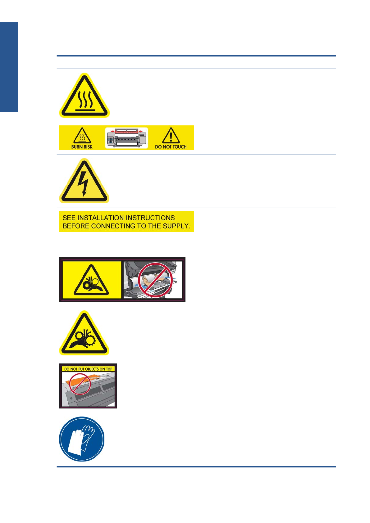
Warning labels
Label Explanation
Risk of burns. Do not touch the internal enclosures of drying
and curing modules of the printer.
Risk of burns. Do not touch the drying enclosure of the printer.
Even after opening the window latch, which disconnects the
power to the drying and curing modules, the internal surfaces
could be hot.
Electric shock hazard. The printer has two input power cords.
A voltage is still present in the drying and curing modules
after the main switch is turned off. There are no operatorserviceable parts inside the printer. Refer servicing to qualified
service personnel. Disconnect all power cords before
servicing.
See installation instructions before connecting to the supply.
Ensure that the input voltage is within the printer's rated
voltage range. The printer requires two dedicated lines, each
protected by a branch circuit breaker according to the rating
of the wall socket outlet. Use only earthed mains outlets and
the power cords supplied by HP with the printer.
Risk of trapped hands. Do not push the roll while loading. Lift
the loading table to ease the spindle into the printer.
Risk of trapped fingers. Do not touch spindle gears while
moving.
Do not put objects on top of the printer. Do not cover the top
fans.
You are recommended to wear gloves when handling ink
cartridges, printhead cleaning cartridges and the printhead
cleaning container.
4 Chapter 1 Introduction ENWW
Page 9

The printer’s main features
Your printer is a color inkjet printer designed for printing high-quality images on flexible substrates from
0.584 m (23 in) to 1.55 m (61 in) wide. Some major features of the printer are shown below:
Printing speeds in draft mode of up to 22.8 m²/h (246 ft²/h).
●
Environmentally friendly, odorless, aqueous latex inks in six colors
●
No special ventilation required, no hazardous waste
●
775 ml ink cartridges
●
Print on a wide range of substrates—including most low-cost, uncoated, solvent-compatible
●
substrates
A range of HP recyclable substrates is available
●
Durable prints with outdoor display permanence up to three years unlaminated, five years
●
laminated
Accurate and consistent color reproduction with automatic color calibration (built-in
●
spectrophotometer) for most substrates
To send print jobs to your printer, you will need Raster Image Processor (RIP) software, which should be
run on a separate computer. RIP software is available from various different companies; it is not
provided with the printer.
Introduction
The printer’s main components
The following views of the printer illustrate its main components.
ENWW
The printer’s main features
5
Page 10
Introduction
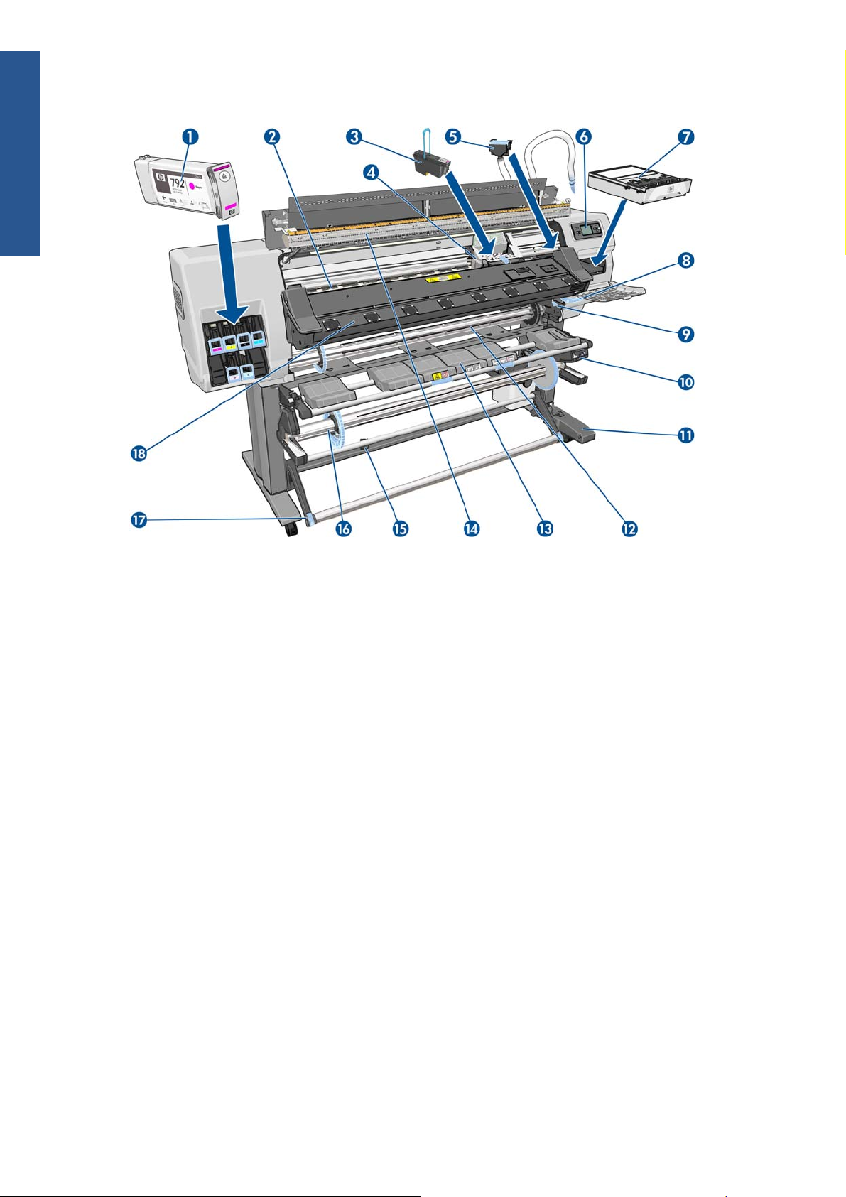
Front view
1. Ink cartridge
2. Platen
3. Printhead
4. Printhead carriage
5. Ink funnel and ink tube assembly
6. Front panel
7. Printhead cleaning cartridge
8. Substrate-adjustment lever
9. Spindle lock lever
10. Take-up reel motor
11. Take-up reel cable and sensor housing unit
12. Spindle
13. Loading table/take-up reel deflector
14. Drying module
15. Take-up reel sensor
16. Take-up reel spindle stop
17. Loop-shaper
18. Curing module
6 Chapter 1 Introduction ENWW
Page 11
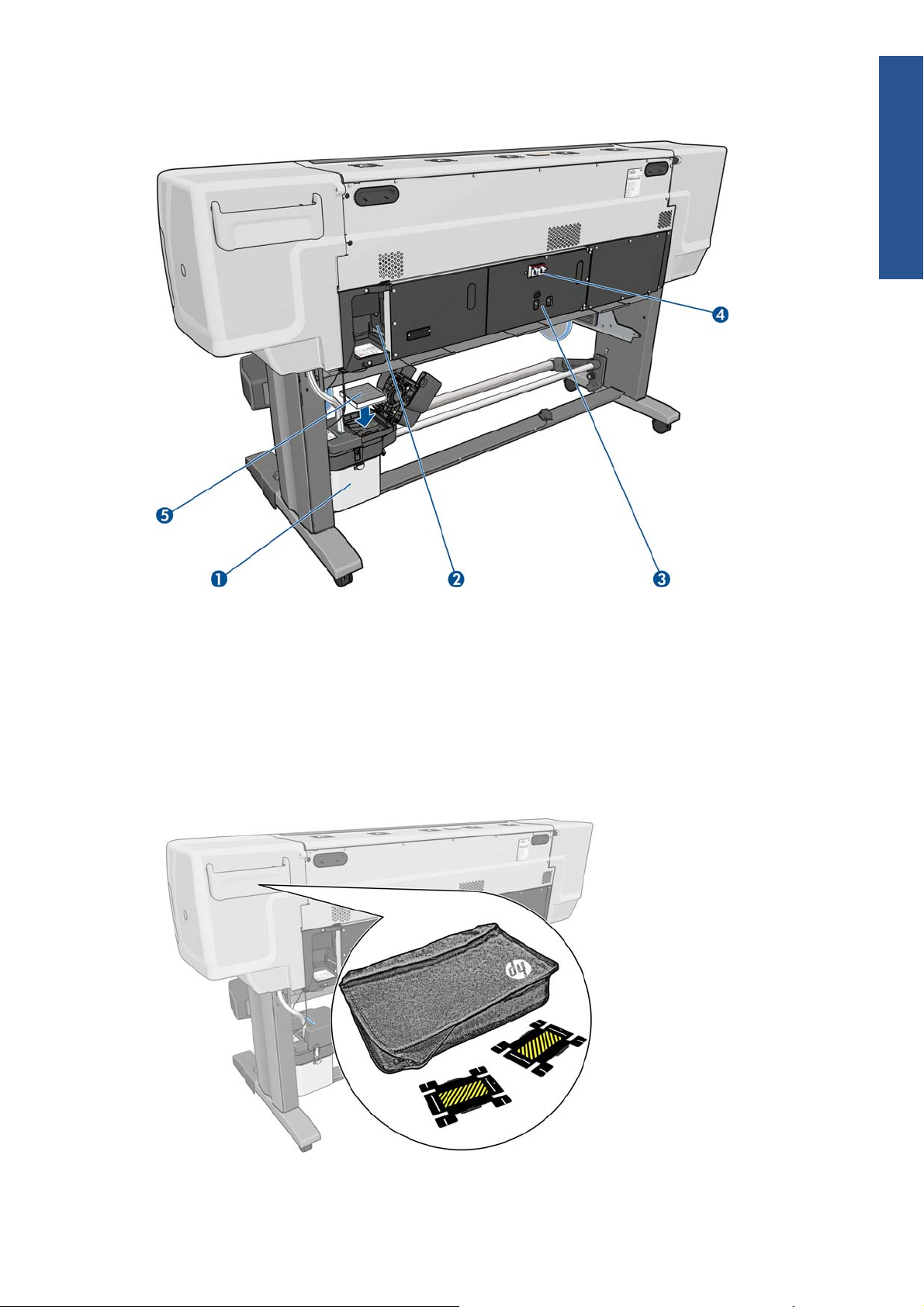
Rear view
Introduction
1. Printhead cleaning container
2. Sockets for communication cables and optional accessories
3. Power switch and power sockets
4. Residual current circuit breakers for the heating components
5. Ink filter
Edge holders case
ENWW
The printer’s main components
7
Page 12
Introduction
The case is normally attached to the rear of the printer, and contains the two edge holders when they
are not in use.
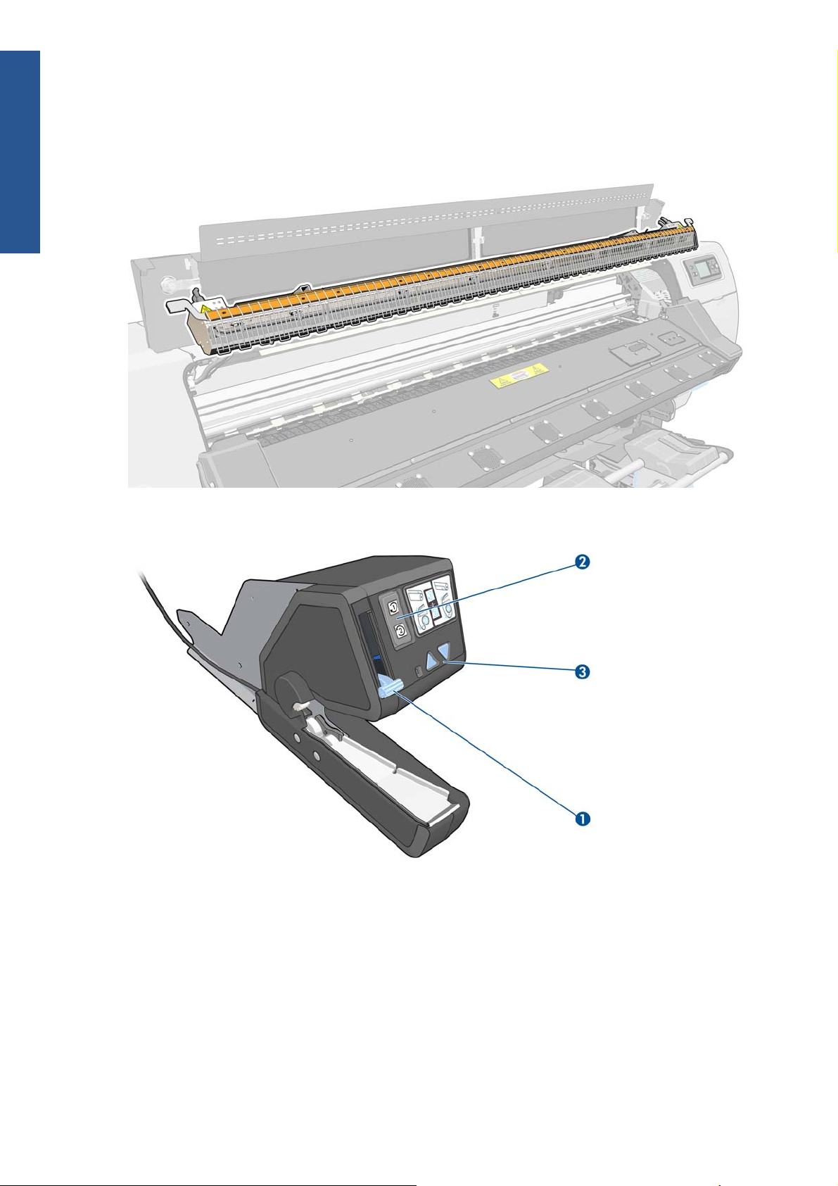
Drying enclosure
Take-up reel motor
1. Take-up reel spindle lever
2. Wind-direction switch
3. Manual winding buttons
8 Chapter 1 Introduction ENWW
Page 13
Loading accessory
The loading accessory helps you to load some substrate types that are difficult to load without it. See
The loading accessory on page 50.
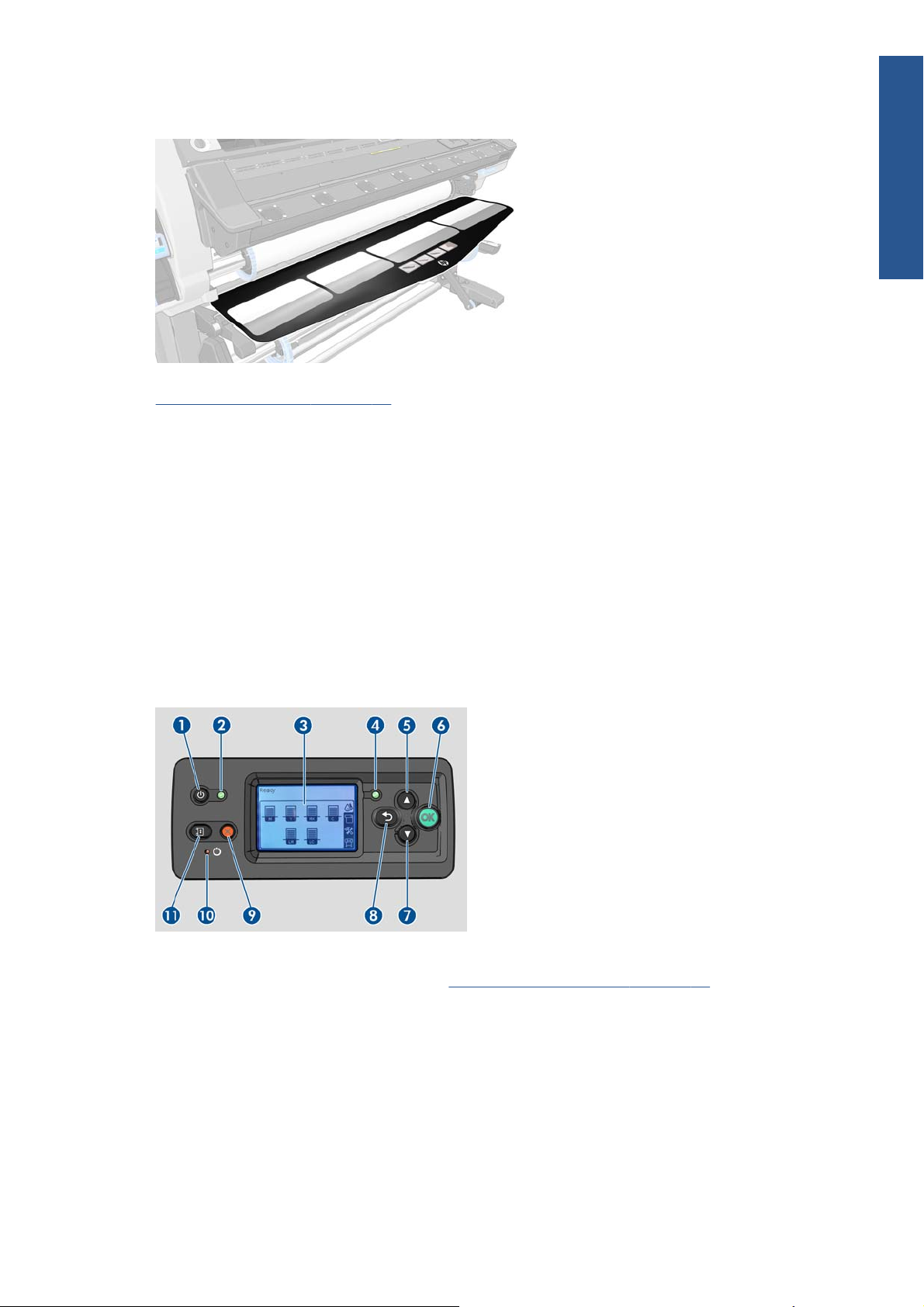
The front panel
Your printer's front panel is located at the front right of the printer. It has the following important
functions:
Assists you in troubleshooting issues
●
Introduction
Is used when performing certain physical operations, such as unloading substrate and maintaining
●
the printer
Displays information in brief about the status of the printer
●
Displays warning and error messages, when appropriate, along with audio alerts to call attention
●
to a warning or message
The front panel has the following components:
1. Power key: To turn the printer off. See
2. Power light: Indicates the printer's power status. If the light is off, the printer is off. If it is solid
green, the printer is on. If it is flashing green, the printer is in transition between on and off.
Turn the printer on and off on page 11.
ENWW
3. Front-panel display: Displays error, warnings and information on using your printer.
4. Status light: Indicates the printer's operational status. If the light is off, the printer is not ready. If it
is solid green, the printer is ready and idle. If it is flashing green, the printer is busy: receiving
data, processing or printing. If it is flashing amber, your intervention is required. If it is solid
amber, a serious error has occurred.
The printer’s main components
9
Page 14

Introduction
5. Up key: To go up in a menu or option, or to increase a value.
6. OK key: To confirm an action while in a procedure or interaction. To enter in a submenu in the
menu. To select a value when given an option.
7. Down key: To go down in a menu or option, or to decrease a value.
8. Back key: To go to the previous step in a procedure or interaction. To go to the upper level, or
leave the option in the menu, or when given an option.
9. Cancel key: To cancel a procedure or interaction.
10. Reset key: To restart the printer (as if it were switched off and switched on again). You will need
an implement with a narrow tip to operate this key.
11. Move substrate key: To move the loaded substrate forwards or backwards. While the printer is
printing, it can be used to fine-tune the substrate advance on the fly.
To highlight an item in the front-panel display, press the Up or Down key until the item is highlighted.
To select an item in the front-panel display, first highlight it and then press the OK key.
When this guide shows a series of front-panel display items like this: Item1 > Item2 > Item3, it
means that you should select Item1, then select Item2, then select Item3.
Information about specific uses of the front panel can be found throughout this guide.
The Embedded Web Server
The Embedded Web Server is a Web server running inside the printer. You can use it to obtain printer
information, manage settings and presets, align printheads, upload new firmware and troubleshoot
problems. Service engineers can use it to retrieve internal information that helps to diagnose printer
problems.
You can access the Embedded Web Server remotely by using an ordinary Web browser running on
any computer. See
The Embedded Web Server window displays three separate tabs. Buttons near the top of each page
provide access to online help and supplies reordering.
Access the Embedded Web Server on page 17.
10 Chapter 1 Introduction ENWW
Page 15

Main tab
The Main tab provides information about the following items.
●
●
●
Setup tab
The Setup tab enables you to complete these tasks.
●
●
●
●
●
●
Substrate, ink, printhead and maintenance status
Temperatures of the drying and curing modules
Substrate and ink usage and accounting
Specify printer settings such as units of measurement and refresh date
Specify network and security settings
Set the date and time
Update firmware
Align printheads
Upload media presets
Introduction
Support tab
The Support tab offers various kinds of help with your printer.
Browse helpful information from a variety of sources
●
Troubleshoot problems
●
Access HP Designjet links for technical support with your printer and accessories
●
Access service support pages that show current and historical data on the usage of your printer
●
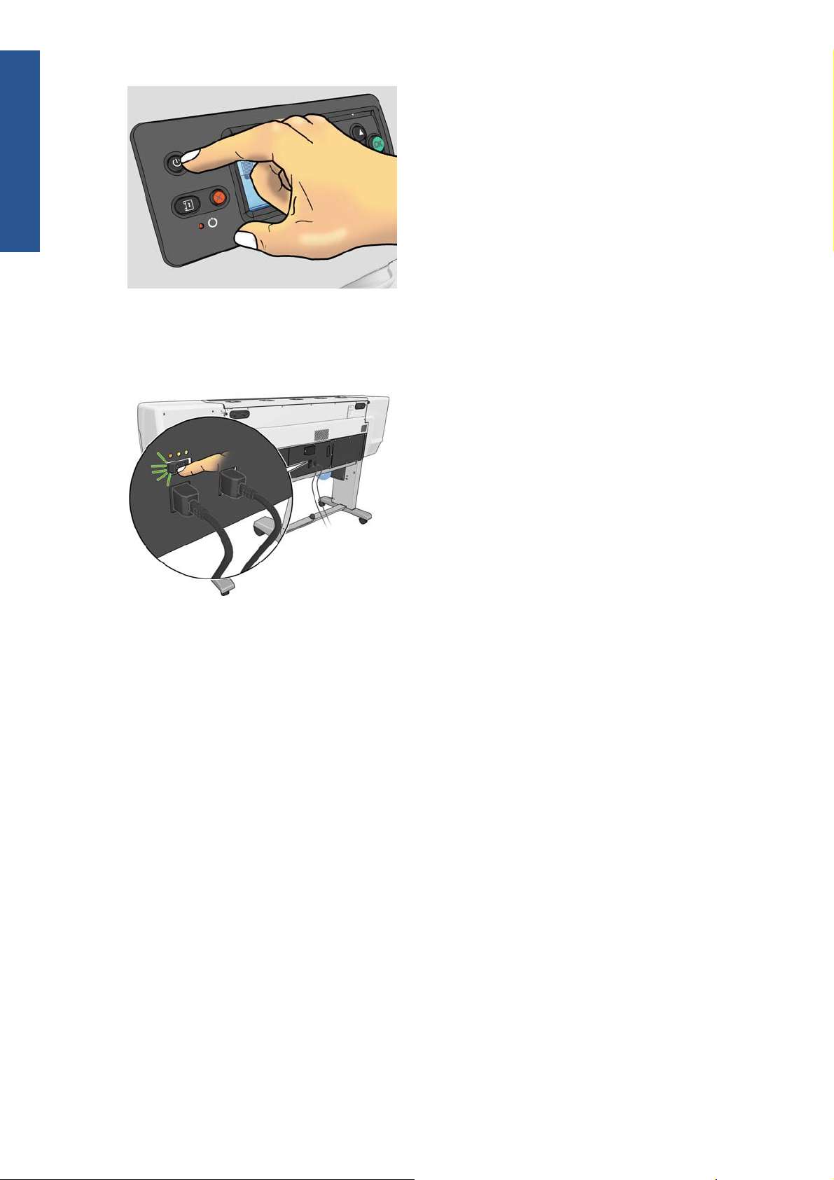
Turn the printer on and off
To turn on the printer, ensure that the power switch at the rear of the printer is turned on, ensure that the
residual current circuit breakers are in the up position, then press the Power button on the front panel.
You can leave the printer on without wasting energy. Leaving it on improves response time. When the
printer has not been used for a certain period of time, it saves power by going into sleep mode. Any
interaction with the printer returns it to active mode, and it can resume printing immediately.
If you want to turn the printer on or off, the normal and recommended method is to use the Power
button on the front panel.
ENWW
Turn the printer on and off
11
Page 16
Introduction
When you turn off the printer this way, the printheads are automatically stored with the printhead
cleaning cartridge, which prevents them from drying out.
However, if you plan to leave the printer turned off for a long period of time, you are recommended to
turn it off using the Power button, and then also turn off the power switch at the rear.
To turn it back on later, use the power switch at the rear, and then press the Power button.
When the printer is turned on, it takes about 5 minutes to initialize itself.
Restart the printer
In some circumstances you may be advised to restart the printer. Please proceed as follows:
1. Press the Power button on the front panel to turn the printer off. Wait a few moments, then press
the Power button again. This should restart the printer. If it does not, continue with step 2.
2. Use the Reset button on the front panel. You will need a non-conductive implement with a narrow
tip to press the Reset button. This normally has the same effect as pressing the Power button, but
may work if the Power button does not.
3. If neither steps 1 nor 2 seems to have any effect, turn off the printer by using the power switch at
the rear of the printer. Check that the residual current circuit breakers are in the up position.
4. Remove the power cords from the power sockets.
5. Wait for 10 seconds.
6. Reinsert the power cords into the power sockets and turn on the printer by using the power switch.
7. Make sure that the Power light on the front panel illuminates. If it does not, use the Power button to
turn on the printer.
12 Chapter 1 Introduction ENWW
Page 17

2 Connectivity and software
instructions
Connection method
Your printer can be connected in the following way.
Connection type Speed Maximum cable length Other factors
Gigabit Ethernet Fast; varies according to
network traffic
NOTE: The speed of any network connection depends on all the components that are used in the
network, which can include network interface cards, hubs, routers, switches, and cables. If any one of
these components cannot operate at high speed, you will have a low-speed connection. The speed of
your network connection can also be affected by the total amount of traffic from other devices on the
network.
Connect to a network
Before you begin, check your equipment:
The printer should be set up and turned on.
●
The Gigabit switch or router should be on and functioning correctly.
●
All computers on the network should be turned on and connected to the network.
●
Connectivity
Long (100 m=328 ft) Requires extra equipment
(switches)
ENWW
The printer should be connected to the switch.
●
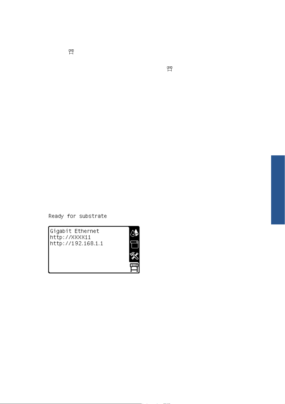
When the printer is connected to the network and turned on, you should see the printer's IP address
appear on the front panel (192.168.1.1 in this example). Make a note of the IP address: you can use it
later to access the Embedded Web Server.
Connection method
13
Page 18

Connectivity
If you see this screen without the IP address, either the printer is not successfully connected to the
network, or your network has no DHCP server. In the latter case, you will have to set the IP address
manually: see the Maintenance and troubleshooting guide.
Refer to the RIP instructions (not provided by HP) to install the software RIP.
14 Chapter 2 Connectivity and software instructions ENWW
Page 19
3 Basic setup options
Printer setup options
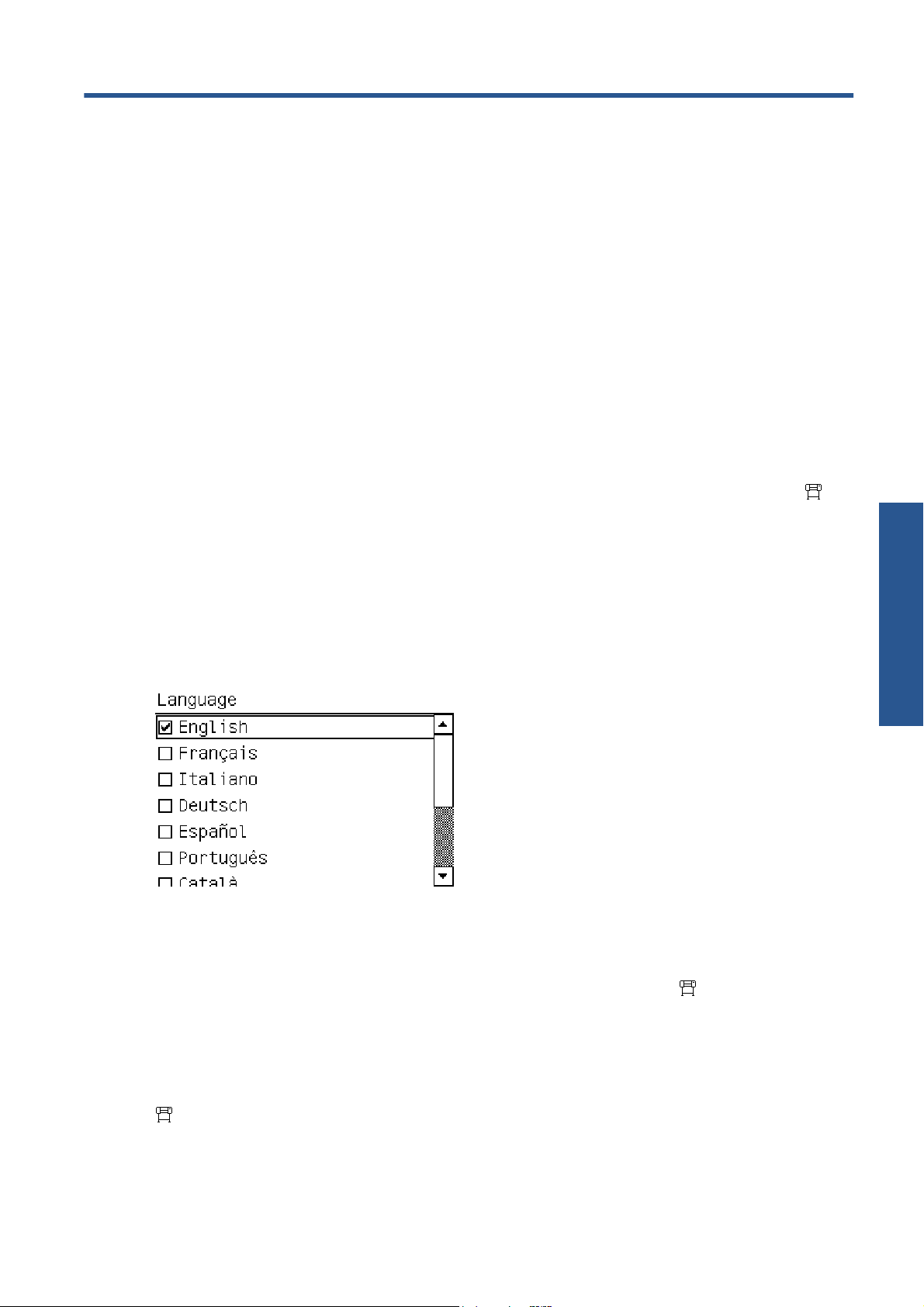
Change the language of the front panel
Two methods are available to change the language that is used for the front-panel menus and
messages.
If you can understand the current front panel language, go to the front panel and select the
●
icon, then select Front panel options > Select language.
If you cannot understand the current front panel language, start with the printer powered off. At
●
the front panel, press the OK button and hold it down. While holding down the OK button, press
the Power button and hold it down. Continue to hold down both buttons until the green light on the
left side of the front panel starts flashing, then release both buttons. You can expect a delay of
about one second. If the green light starts flashing without any delay, you may need to start again.
Whichever method you used, the language selection menu should now appear on the front panel.
Highlight your preferred language, then press the OK button.
View or set the date and time
To view or set the printer's date and time, go to the front panel and select the icon, then Front
panel options > Date and time options.
Set altitude
If your printer is operating at a significant altitude above sea level, go to the front panel and select the
icon, then Select altitude, to tell the printer its operating altitude.
Basic setup options
ENWW
Printer setup options
15
Page 20

Request e-mail notification of specific error conditions
1. In the Embedded Web Server, go to the E-mail server page on the Setup tab and ensure that the
following fields are correctly filled in:
SMTP server. This is the IP address of the outgoing mail server (Simple Mail Transfer
●
Protocol [SMTP]) that processes all e-mail messages from the printer. If the mail server
requires authentication, e-mail notifications will not work.
Printer e-mail address. Each e-mail message that the printer sends must include a return
●
address. This address does not need to be a real, functional e-mail address, but it should be
unique, so that recipients of the message can identify the printer that sent it
2. Go to the Notification page, which is also on the Setup tab.
3. Click the New icon to request new notifications, or click the Edit icon to edit notifications that
have already been set up. Then specify the e-mail addresses to which notifications are sent, and
select the incidents that result in notification messages.
Change the cool-down delay
Basic setup options
Change the sleep mode setting
Turn the buzzer on or off
Change the front panel display contrast
When there are no more jobs to print, the printer's drying and curing heaters remain on for a while, in
case another job arrives. To choose how long they remain switched on in this situation, go to the front
panel and select the
Select a time from 5 to 60 minutes, then press the OK button.
If the printer is left turned on but unused for a certain period of time, it automatically goes into sleep
mode to save power. The default period of time it waits is 30 minutes. To change the time the printer
waits before it goes into sleep mode, go to the front panel and select the
panel options > Sleep mode wait time. Highlight the wait time that you want, then press the OK
button.
To turn the printer's buzzer on or off, go to the front panel and select the icon, then Audio alert,
then on or off. By default, the buzzer is on.
To change the contrast of the front-panel display, select the icon, then Front panel options >
Select display contrast, then select a value by using the Up or Down button. Press the OK button to
save the value.
icon, then Substrate handling options > Cooldown wait when idle.
icon, then select Front
Change the units of measurement
To change the units of measurement that appear on the front panel, select the icon, then Front
panel options > Select units, then English or Metric.
The units of measurement can also be changed in the Embedded Web Server.
16 Chapter 3 Basic setup options ENWW
Page 21
Restore factory settings
To restore the printer settings to their original values as set in the factory, go to the front panel and
select the
settings except the Gigabit Ethernet settings.
icon, then Resets > Restore factory settings. This option restores all of the printer
To restore the Gigabit Ethernet factory settings, select the
Ethernet > Restore factory settings.
icon, then Connectivity > Gigabit
Embedded Web Server setup options
Access the Embedded Web Server
Use the Embedded Web Server to view printer information remotely through an ordinary Web browser
running on any computer.
The following browsers are known to be compatible with the Embedded Web Server:
Internet Explorer 6 and later for Windows
●
Safari 2 and later for Mac OS X
●
Mozilla Firefox 2 and later
●
Google Chrome 7
●
To use the Embedded Web Server on any computer, open your Web browser and type the printer's
URL. The printer's URL appears on the status screen on the printer's front panel (http://192.168.1.1 in
this example):
If you follow these instructions but fail to open the Embedded Web Server, see the Maintenance and
troubleshooting guide.
Change the language of the Embedded Web Server
The Embedded Web Server functions in the following languages: English, Portuguese, Spanish,
Catalan, French, Italian, German, Simplified Chinese, Traditional Chinese, Korean, and Japanese. It
uses the language that you specified in your Web browser options. If you specify a language that it
cannot support, it functions in English.
To change the language, change your Web browser's language setting. For example, in Internet
Explorer version 6, go to the Tools menu and select Internet Options > Languages. Make sure
that the language you want is at the top of the list in the dialog box.
Basic setup options
ENWW
To complete the change, close and reopen your Web browser.
Embedded Web Server setup options
17
Page 22

Restrict access to the printer
Basic setup options
From the Embedded Web Server, you can select Setup > Security to set an administrator password.
Once set, this password must be given in order to perform the following printer functions.
Change printer settings.
●
Update the firmware.
●
Change the printer's date and time.
●
Clear accounting information.
●
For more information, see the Embedded Web Server's online help.
If you forget the administrator password, you can delete the current password from the front panel:
select the
password.
icon, then Connectivity > Advanced > Embedded Web Server > Reset EWS
18 Chapter 3 Basic setup options ENWW
Page 23

4 Handle the substrate
Overview
You can print on a wide variety of printing materials, all of which are referred to in this guide as
substrates.
Substrate tips
Choosing the correct substrate for your needs is an essential step in ensuring good print quality.
Here are some tips about substrate usage.
Allow all substrates to adapt to room conditions, out of the packaging, for 24 hours before using
●
them for printing.
Handle film and photo substrates by the edges, or wear cotton gloves. Skin oils can be transferred
●
to the substrate, leaving fingerprint marks.
Keep the substrate tightly wound on the roll throughout the loading and unloading procedures. To
●
make sure that the roll stays tightly wound, consider using tape to stick the leading edge of the roll
to the core just before removing the roll from the printer. You can keep the roll taped during
storage. If the roll starts to unwind, it can become difficult to handle.
NOTE: The use of tape to stick the leading edge of the roll to the core is especially important for
heavy substrates, because the inherent stiffness of the substrate can cause it to loosen and unwind
from the core.
Using the take-up reel gives the printer better control of the substrate.
●
Print quality could be impaired if you use a substrate that is unsuitable for your image.
●
sure that the appropriate print-quality setting is selected in the RIP.
Make
●
Whenever you load a roll, the front panel prompts you to specify the substrate family that you are
●
loading. For good print quality, it is essential to specify this correctly. Check that the substrate
Handle the substrate
ENWW
Overview
19
Page 24

belongs to the family named on the front panel, and check also that it matches the substrate profile
in the RIP.
If the substrate family shown on the front panel does not correspond to the substrate that you have
●
loaded, take one of the following actions:
Reload the roll into the printer and select the correct substrate family. See
◦
Unload a roll from
the printer on page 33 and Load a roll into the printer (automatically) on page 27.
At the printer's front panel, select the
◦
Change loaded substrate.
NOTE: Substrate advance calibration is not performed when the substrate family is
changed from the front panel.
CAUTION: Removing the substrate from the printer manually without using the front panel could
damage the printer. Do this only when necessary to clear a substrate jam.
Supported substrate families
Substrate family Description
Self-adhesive Printable PVC films with adhesive on one side and a detachable liner. There are two main vinyl types
classified by manufacturing process and application purpose: calendered (for flat surfaces) and cast
(for complex 3D curves). The film may have different finishes: white, finished, transparent, reflective
or perforated. Perforated substrates may need manual rather than automatic printhead alignment.
Examples: HP Air Release Adhesive Gloss Cast Vinyl, Avery MPI3000 (calendered), Avery
MPI1005 (cast), 3M IJ-380 (cast)
Banner Usually a polyester mesh (which provides mechanical resistance) coated with PVC. There are also
recyclable versions to cover the same applications (green banners). Banners have a wide range of
grammage and can be grouped into frontlit, backlit and block-out categories.
Examples: HP Durable Frontlit Scrim Banner, Ultraflex Normandy Pro, Verseidag banners
icon, then select View loaded substrate >
Handle the substrate
Textile Printable textile substrates are usually made of polyester or cotton yarns. Some open or light textile
Film Usually a polyester film, although there are other materials such as PVC or PC. Generally these
Synthetic paper Substrates manufactured using synthetic resins, mainly extruded from polypropylene (PP). They have
Paper-aqueous Light paper-based (cellulose) substrates with a coating compatible with water-based inks, or offset
Paper-solvent Paper-based (cellulose) substrates with a top-coating compatible with solvent inks. Weight is usually
substrate types come with a removable liner to prevent the ink from passing through the substrate.
Textile materials that are very stiff (such as canvases) should preferably be loaded as “Low-temp."
substrate. These substrates may need manual rather than automatic printhead alignment.
Stretchable and/or flimsy textiles may require the use of take up reel and/or edge holders.
substrates are used for backlit applications. Select this family setting for substrates that resist
temperatures over 95°C (200°F), otherwise load them preferably as "Low-temp." substrate. These
substrates may need manual rather than automatic printhead alignment.
Example: Intelicoat SBL-7 Polyester Backlit Film
characteristics similar to those of plastic film, but their appearance and properties are similar to
regular paper made from wood pulp.
Examples: Yupo FEB 250, Ilford Omnijet Dry Glossy Portable Display Film
paper. These substrates are not compatible with solvent inks. Weight is usually around 100 g/m².
Example: HP Heavyweight Coated Paper
between 120 and 200 g/m².
Examples: HP Blue Back Billboard Paper, Intelicoat GPIOF140, blue back substrates
20 Chapter 4 Handle the substrate ENWW
Page 25
Substrate family Description
Low-temp. (including
HP Photorealistic)
Mesh An open and resistant polyester mesh coated with PVC and mainly used for building wrap
Substrates sensitive to high temperatures (PP, HDPE, PET thin films), and paper-based (cellulose)
substrates with top-coating that have a high stiffness and grammage (200 g/m² or higher).
Example: HP Photorealistic Poster Paper
applications. Some of these substrates have a removable liner to prevent the ink from passing
through the substrate. These substrates may need manual rather than automatic printhead alignment.
Example: Ultraflex Stripmesh
Must be used with the 2 inch spindle (see Accessories on page 83)
The Latex Media Finder is a tool that allows you to search for substrates (HP and third-party) that have
been tested and shown to be compatible with your printer. The tool allows searching by manufacturer
brand, substrate type, application or geographical availability. It can be found at
http://www.hp.com/go/latexmediafinder/.
Supported HP substrates
Substrate 2 inch Re
Banners
cycle
Take
Back
Color
Pro
FSC® PEFC Oeko
HP HDPE Reinforced Banner
HP Double-sided HDPE Reinforced Banner
HP Durable Frontlit Scrim Banner
HP Everyday Matte Polypropylene
HP Durable Semi-gloss Display Film
Self-adhesive materials
HP Air Release Adhesive Gloss Cast Vinyl
HP One-view Perforated Adhesive Window Vinyl
HP Permanent Gloss Adhesive Vinyl
HP Permanent Matte Adhesive Vinyl
HP Everyday Adhesive Matte Polypropylene
Films
HP Backlit Polyester Film
Fabrics
Handle the substrate
ENWW
HP Heavy Textile Banner
HP Light Textile Display Banner
Papers
HP PVC-free Wall Paper (Greenguard, AgBB)
•
•
Overview
21
Page 26
Substrate 2 inch Re
cycle
Take
Back
Color
Pro
FSC® PEFC Oeko
HP White Satin Poster Paper
HP Photo-realistic Poster Paper
HP Blue Back Billboard Paper
HP Coated Paper
HP Universal Coated Paper
HP Universal Heavyweight Coated Paper
HP Heavyweight Coated Paper
HP Universal Bond Paper
HP Super Heavyweight Plus Matte Paper
Specialty materials
HP DuPont Tyvek Banner
HP Satin Canvas
HP Collector Satin Canvas
•
•
•
•
••
Key
Handle the substrate
Must be used with the 2 inch spindle (see Accessories on page 83)
Recycle: Substrates that can be recycled through commonly available recycling
programs.
TakeBack: HP offers the HP Large-format Media TakeBack program in North America
and Europe through which most HP recyclable substrates can be returned, availability
varies. For details, visit
recycling opportunities for these products are currently only available in limited areas.
Customers should consult local recycling resources for recycling these products.
Papers bearing the ColorPRO logo are manufactured to meet a strict set of quality
specifications, with performance criteria such as black optical density, color gamut line
edge acuity and color-to-color bleed. The performance and quality of ColorPRO papers
are verified by an independent testing agency.
FSC®-certified papers carry the Forest Stewardship Council® (FSC) Mixed Sources
label, signifying that these substrates support the development of responsible forest
management worldwide. The wood comes from FSC®-certified well-managed forests,
company-controlled sources and/or recycled material.
http://www.hp.com/recycle/. Aside from this program,
22 Chapter 4 Handle the substrate ENWW
Page 27

The Program for the Endorsement of Forest Certification label demonstrates that certified
HP papers come from forests that are managed sustainably.
Unprinted HP Heavy Textile Banner, HP Light Textile Display Banner and HP Wrinklefree Flag with Liner are Oeko-Tex-certified according to Oeko-Tex Standard 100, which
is a globally uniform testing and certification system for textile raw materials,
intermediate and end products at all stages of production. Tested for emissions of
chemicals such as pesticides, allergy-inducing dyestuffs or tin-organic compounds.
Greenguard HP PVC-free Wall Paper printed using HP Latex Inks is listed in the GREENGUARD
product list of low-emitting products and is tested to the GREENGUARD Children &
Schools standard. The print is neither GREENGUARD nor GREENGUARD Children &
Schools Certified. The GREENGUARD Environmental Institute is an American National
Standards Institute (ANSI) authorized standards developer that establishes acceptable
indoor air standards for indoor products, environments, and buildings.
http://www.greenguard.org/.
See
AgBB The Committee for Health-related Evaluation of Building Products, AgBB, establishes the
fundamentals for a uniform and reproducible health-related evaluation of building
products in Germany, including criteria for testing and an evaluation scheme for healthrelated evaluation of volatile organic compound (VOC) emissions from building
products used for application indoors.
Porous substrates
Substrates of limited porosity may be used with this printer, but very porous substrates could damage
the printer.
To check the porosity of your substrate, see the Maintenance and troubleshooting guide.
If you use a substrate that is too porous, or fail to clean the platen as recommended, you could
experience a decrease in print quality that would require a service repair not covered by your
warranty.
Load a roll onto the spindle
1. Make sure that the printer wheels are locked (the brake lever is pressed down) to prevent the
printer from moving.
Handle the substrate
ENWW
Porous substrates
23
Page 28
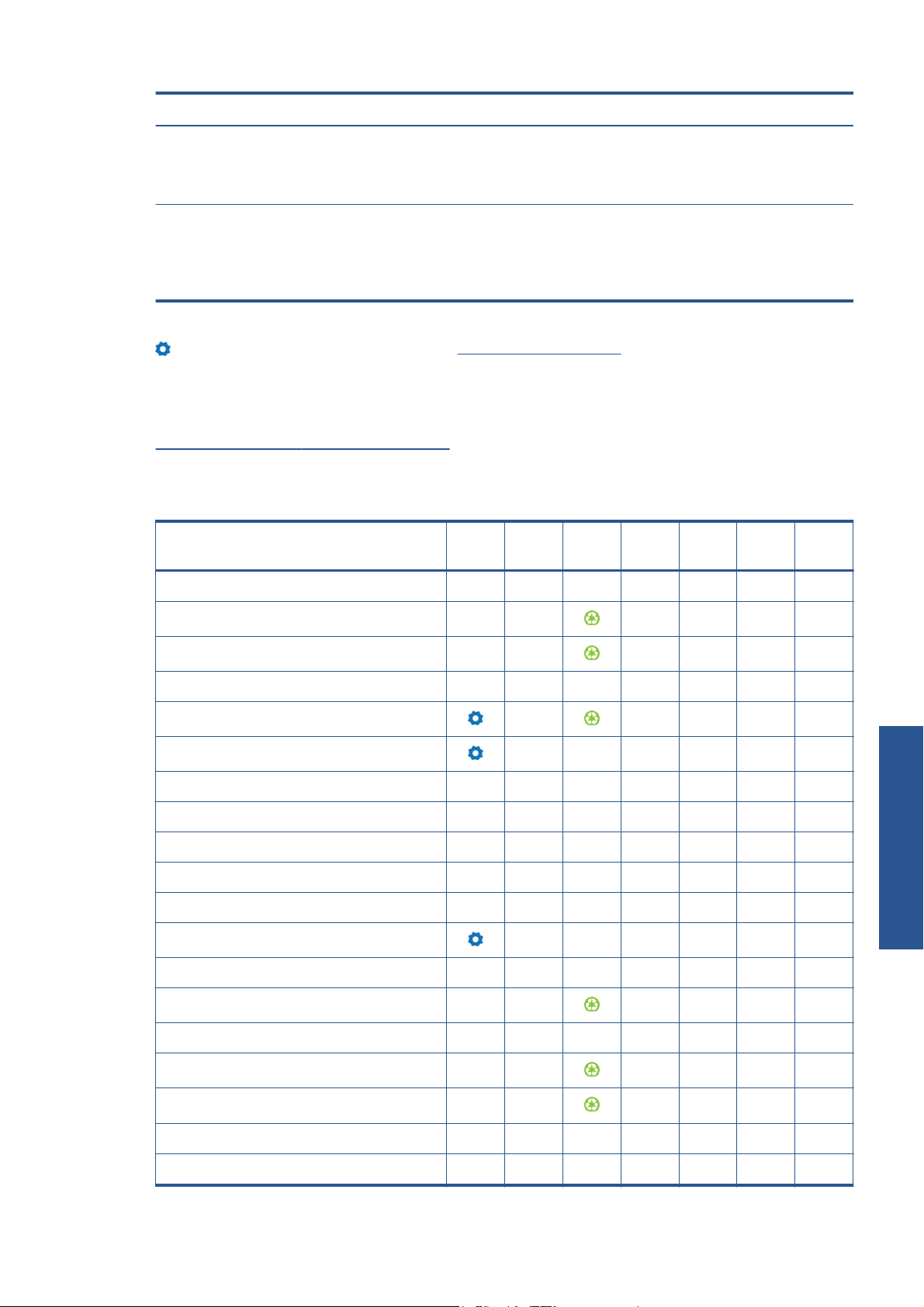
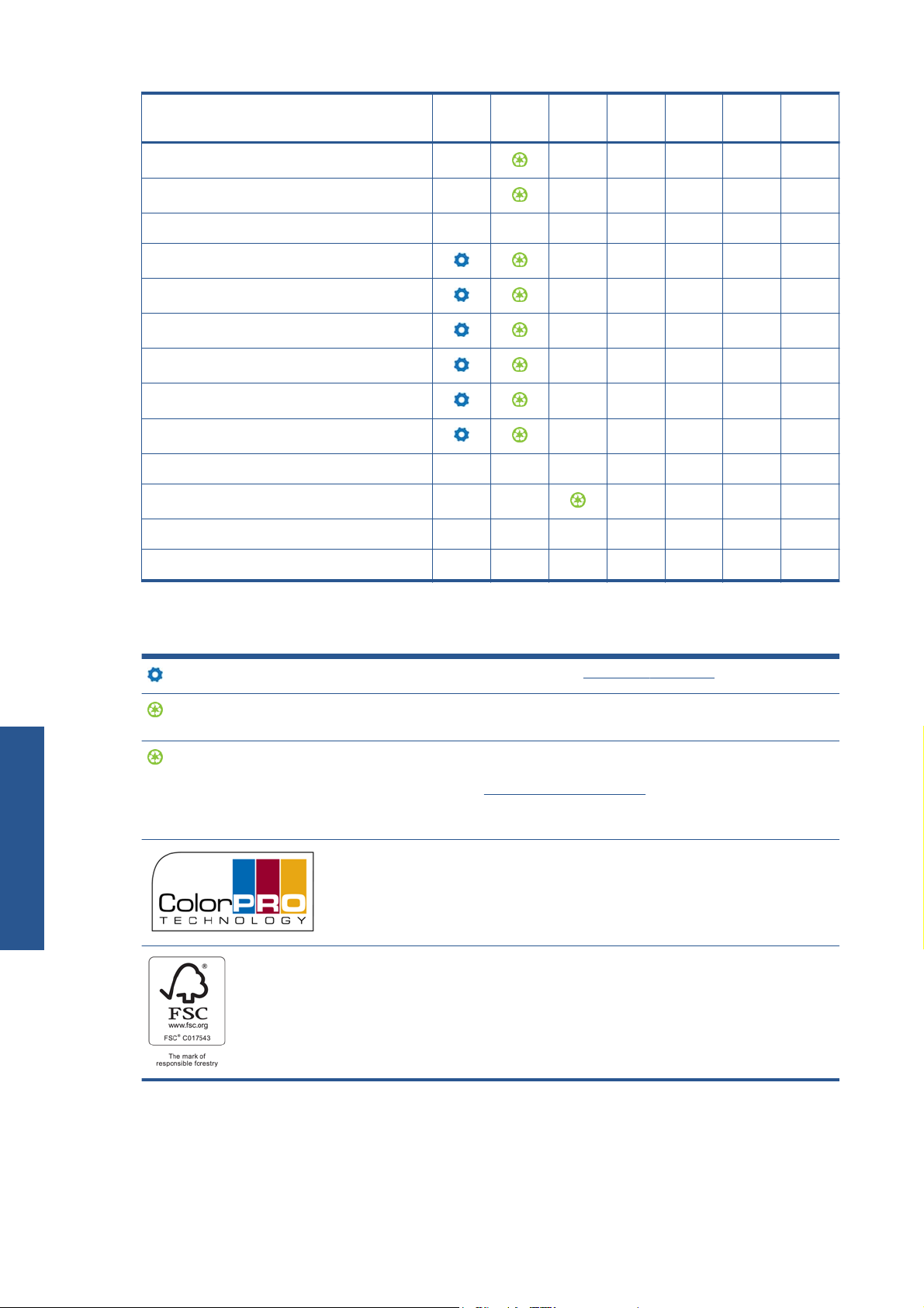
2. Lift the spindle lock lever to disengage the spindle.
3. Remove the first end of the spindle from the right side of the printer, then move the spindle to the
right in order to extract the other end. Do not insert your fingers into the spindle supports during
the removal process.
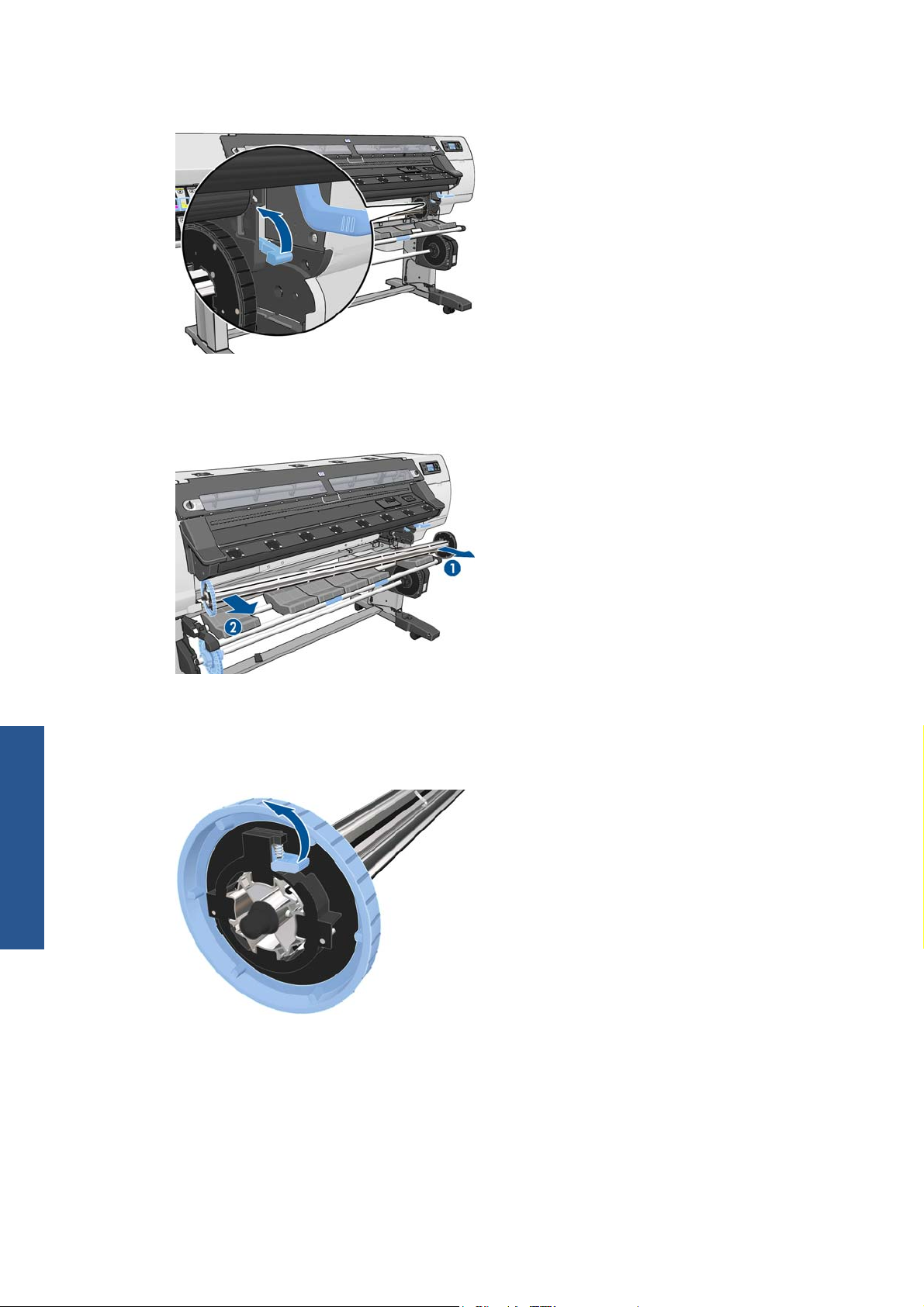
The spindle has a stop at each end to keep the roll in position. Remove the blue stop at the left end
to mount a new roll (the stop at the other end can also be removed, if you wish). The stop slides
Handle the substrate
along the spindle to hold rolls of different widths.
4. Slide the lever-lock on the blue stop to the unlocked position.
24 Chapter 4 Handle the substrate ENWW
Page 29
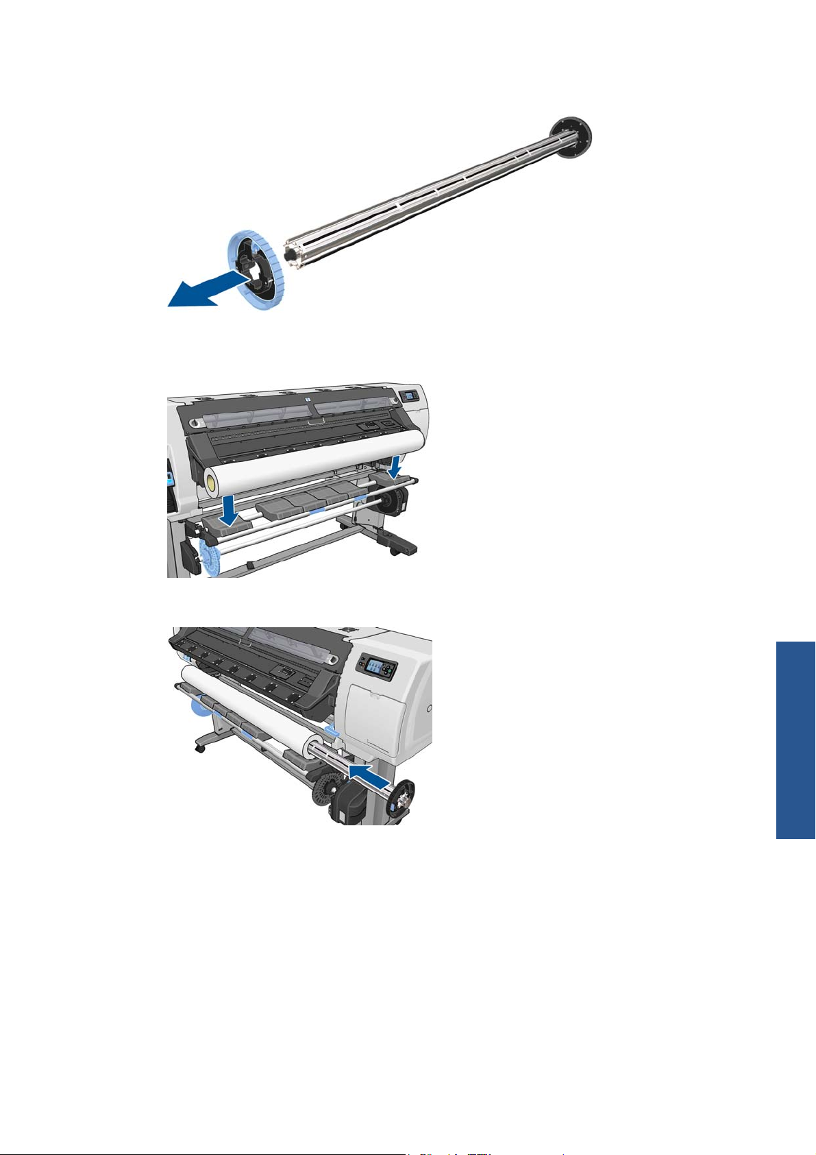
5. Remove the stop from the left end of the spindle.
6. Rest the roll of substrate that you want to load on the loading table. If the roll is long and heavy,
you may need two people to handle it.
7. Slide the spindle into the roll.
Handle the substrate
ENWW
Load a roll onto the spindle
25
Page 30

8. The right stop of the spindle has two positions: one for rolls of the printer's maximum width, and
another for narrower rolls. Remember to use the second position for narrower rolls, which
improves the drying process and allows higher printing speeds.
9. Put the blue stop on to the upper end of the spindle, and push it towards the end of the roll.
TIP: If the cardboard core of the substrate is longer than the substrate, you can load the
substrate without inserting the blue stop, but care should be taken when unloading the substrate,
Handle the substrate
as the loading/unloading table is designed to be used with the blue stop in place.
TIP: When loading a roll that is 1549 mm (61 in) wide, you may find it easier to load without
stops (remove both stops).
10. Slide the lever-lock to the locked position.
26 Chapter 4 Handle the substrate ENWW
Page 31

11. Lift the loading table to ease the spindle into the printer.
CAUTION: To avoid trapping your fingers, do not push the roll with your hands.
If you regularly use different substrates, you can change rolls more quickly if you pre-load rolls of
different substrates on different spindles. Extra spindles are available for purchase.
Load a roll into the printer (automatically)
To start this procedure, you need to have a roll loaded on the spindle. See Load a roll onto the spindle
on page 23.
The normal minimum substrate width is 23 inches (584 mm). To load substrates down to a minimum
width of 10 inches (254 mm), go to the front panel and select the
handling options > Enable narrow substrate. With this option, print quality is not guaranteed.
icon, then select Substrate
TIP: To load a roll of textile material, see The loading accessory on page 50.
TIP: When loading very thin or very thick substrates, or substrates with a tendency to curl, you should
follow the manual loading procedure to reduce the risk of substrate jams and printhead crashes; see
Load a roll into the printer (manually) on page 30.
1.
At the printer's front panel, select the
icon, then select Substrate load > Load roll.
Handle the substrate
ENWW
Load a roll into the printer (automatically)
27
Page 32

2. Carefully insert the leading edge of the substrate above the black-ribbed roller, making sure the
substrate remains taut during the process. Avoid rewinding the substrate manually, unless the
printer asks you to do so.
WARNING! Take care not to touch the rubber wheels on the platen while loading substrate.
These wheels can rotate and trap skin, hair or clothing.
WARNING! Take care not to push your fingers inside the printer's substrate path.
The printer beeps when it detects and accepts the leading edge of the substrate.
3. The front panel may prompt you to remove the edge holders from the platen, if the printer believes
they are present (it may be wrong: it has no sensor to detect them).
4. Select the type of substrate you are loading.
Handle the substrate
NOTE: You should select the name of the particular substrate that you are using in your RIP
software, not in the front panel.
NOTE: The RIP substrate setting will overwrite the front panel setting.
5. If the roll of substrate you are loading is new, select the length in the front panel. If the substrate
has been used before, and the tracking feature was used, select the substrate remaining. For
information on the substrate length tracking feature see
Substrate length tracking on page 57
28 Chapter 4 Handle the substrate ENWW
Page 33

6. The printer checks the substrate in various ways and may ask you to correct problems with skew or
tension.
NOTE: You can specify the maximum permitted amount of skew at the front panel: select the
icon, then select Substrate handling options > Max skew setting.
7. Wait until the substrate emerges from the printer, as shown below.
NOTE: If you have an unexpected problem at any stage of the substrate loading process, see
the Maintenance and troubleshooting guide.
8. If you are loading transparent substrate without opaque borders, you are asked to enter the width
of the substrate and the distance of the right edge from the printer's side plate (as indicated by the
ruler on the front of the curing module).
9. If you have chosen double-sided printing, the front panel may ask a question about it at this point.
10. The printer calibrates the substrate advance.
11. The printer indicates that it is ready for printing.
Take care not to cover the top fans.
Handle the substrate
ENWW
Load a roll into the printer (automatically)
29
Page 34

For instructions on how to use the take-up reel see The take-up reel on page 34.
Load a roll into the printer (manually)
The manual loading process should be used in the following cases:
The substrate is unusually thin or unusually thick.
●
The substrate has ragged edges.
●
The substrate tends to curl at the edges.
●
The printing side of the substrate faces outwards.
●
In other cases, the automatic loading process is recommended: see
(automatically) on page 27.
To start this procedure, you need to have a roll loaded on the spindle. See
on page 23.
The normal minimum substrate width is 23 inches (584 mm). To load substrates down to a minimum
width of 10 inches (254 mm), go to the front panel and select the
handling options > Enable narrow substrate. With this option, print quality is not guaranteed.
TIP: To load a roll of textile material see The loading accessory on page 50.
1.
At the printer's front panel, select the
Handle the substrate
This step is optional: you can alternatively begin at step 2.
The front panel may prompt you to remove the edge holders from the platen, if the printer believes
they are present (it may be wrong: it has no sensor to detect them).
Load a roll into the printer
Load a roll onto the spindle
icon, then select Substrate
icon, then select Substrate load > Manual load.
2. Lift the substrate-adjustment lever as far up as it will go.
30 Chapter 4 Handle the substrate ENWW
Page 35

3. Carefully insert the leading edge of the substrate above the black-ribbed roller, making sure the
substrate remains taut during the process. Avoid rewinding the substrate manually, unless the
printer asks you to do so. The front panel displays the following.
4. Continue to feed the substrate until it reaches the printing platen. Open the window to help pull
the substrate through.
WARNING! Do not touch the printer's drying enclosure. Even after you have opened the
window latch, which disconnects the power to the drying and curing modules, the internal
surfaces could be hot.
TIP: If the substrate you are using tends to curl, keep feeding the substrate until the edge is out of
the printer. You are also recommended to use the take-up reel, or to disable the cutter from the
front panel if not using the take-up reel.
5. Pull down the substrate-adjustment lever as far as it will go.
Handle the substrate
ENWW
Load a roll into the printer (manually)
31
Page 36

6. Select the type of substrate you are loading.
NOTE: You should select the name of the particular substrate that you are using in your RIP
software, not in the front panel.
TIP: When loading very thin substrates, always select the substrate type as Banner to minimize
the vacuum pressure applied while loading; when loading very thick substrates, always select the
substrate type as HP Photorealistic to maximize the vacuum pressure. After loading and before
printing, go to the front panel and change to the correct type for the substrate you are loading:
select the
TIP: When manually loading textile substrates that you intend to use with the take-up reel, before
selecting the substrate type it is a good idea to press the Move substrate key on the front panel
and use the front panel to advance the substrate beyond the point where it may jam in the printer.
This avoids the possibility of a substrate jam at this stage and also some other substrate issues;
and it enables you to skip the normal check for skew.
icon, then select View loaded substrate > Change loaded substrate.
7. The printer checks the substrate in various ways and may ask you to correct problems with skew or
tension.
NOTE: You can specify the maximum permitted amount of skew at the front panel: select the
icon, then select Substrate handling options > Max skew setting.
Handle the substrate
8. If you are loading transparent substrate without opaque borders, you are asked to enter the width
of the substrate and the distance of the right edge from the printer's side plate (as indicated by the
ruler on the front of the curing module).
9. If you have chosen double-sided printing, the front panel may ask a question about it at this point.
10. The printer calibrates the substrate advance.
11. The printer indicates that it is ready for printing.
Take care not to cover the top fans.
32 Chapter 4 Handle the substrate ENWW
Page 37

Load a cut sheet into the printer
The printer is designed to be used with rolls of substrate. It is possible to load cut sheets into the printer,
but print quality cannot be guaranteed, and you may have some difficulty in avoiding skew.
The sheet should be at least 1067 mm (42 in) long.
●
Load the sheet by following the normal roll loading process (automatic or manual, depending on
●
the substrate).
During the loading process, the printer tries to detect the winding direction of the roll by turning
●
the spindle in both directions. When the substrate is not attached to the spindle, the following
message appears.
To continue loading, select Skip check – would affect IQ.
A cut sheet is likely to be loaded with excessive skew, and the printer may not be able to correct it
●
automatically. If the skew as measured by the printer exceeds 3 mm/m, you are recommended to
stop loading and try again. However, if the skew is tolerable, you can consider skipping the
automatic skew correction. To do so, when prompted, choose Continue with current skew.
Unload a roll from the printer
1. If you used the take-up reel during printing, unload the printed roll from the take-up reel. See
Unload a roll from the take-up reel on page 47.
ENWW
2.
On the printer's front panel, select the
3. Press the OK button on the front panel as many times as needed to rewind the substrate.
4. Lift the spindle lock lever.
icon, then select Substrate unload > Unload roll.
Load a cut sheet into the printer
Handle the substrate
33
Page 38

5. Remove the roll from the printer, pulling out the right end on the right side of the printer first. Do
not insert your fingers into the spindle supports during the removal process.
The take-up reel
The take-up reel must be enabled and operated from the front panel. When the take-up reel is enabled,
the “Take-up reel enabled” message appears on the Substrate tab on the front panel. If the take-up
reel is not enabled and you would like to enable it, select the
Enable take-up reel.
icon, then select Take-up reel >
The loop-shapers
When in use, the take-up reel requires a dangling loop of substrate weighed down by a loop shaper.
There are two different loop-shapers provided with the printer, to be used with different substrate types.
The heavy loop-shaper is used with banner, textile and mesh substrates. It is attached to supports
●
on either side of the substrate. The spindle stops should not be used with this loop-shaper.
Handle the substrate
34 Chapter 4 Handle the substrate ENWW
Page 39

The light loop-shaper is used with all other substrates. It lies in the substrate loop, supported only
●
by the substrate, unattached at either end. It should be the same width as the substrate; therefore,
it is supplied in sections of different widths that can be fitted together. The spindle stops should be
used with this loop-shaper.
There are two slightly different procedures for loading a roll onto the take-up reel, depending on which
substrate type and therefore which loop-shaper is used: see See
(banner/textile/mesh substrates) on page 35 and Load a roll onto the take-up reel (other substrates)
on page 41.
Load a roll onto the take-up reel
Load a roll onto the take-up reel (banner/textile/mesh substrates)
1.
On the printer's front panel, select the
reel.
2. The front panel offers you the choice of loading the take-up reel immediately, or during printing.
If you decide to load the take-up reel during printing, familiarize yourself with the procedural
steps. Loading the take-up reel during printing requires you to complete the procedure while the
printer is feeding and printing substrate. Loading the take-up reel during printing saves
approximately 1 m (3 ft) of substrate.
TIP: If you have already loaded the take-up reel, but the printer fails to recognize that it is
loaded, you can save some time by selecting Load it during printing.
The following steps assume that you have decided to load immediately. If you decide to load later,
during printing, you must complete the same operations without guidance from the front panel.
icon, then select Take-up reel > Enable take-up
Handle the substrate
ENWW
The take-up reel
35
Page 40

3. For easier access to the take-up reel spindle, lift the loading table into its upright position.
4. Unlock the take-up reel spindle by pushing the spindle lever to its uppermost position.
5. Remove the take-up reel spindle.
Handle the substrate
NOTE: The take-up reel spindle is longer than the input spindle: the two are not
interchangeable.
36 Chapter 4 Handle the substrate ENWW
Page 41

6. Lift the lever in each case to remove both of the stops from the spindle; they will not be used.
7. Load the core onto the take-up reel spindle. The core should be at least as wide as the substrate.
8. Load the take-up reel spindle into the printer by pushing firmly on both ends of the spindle.
Handle the substrate
ENWW
The take-up reel
37
Page 42

9. Press the OK button on the front panel.
Advance the substrate using the arrows on the front panel. Make sure that the substrate passes in
front of the loading table, as shown.
10. Pull down the center of the substrate's leading edge to straighten the substrate. Do not attempt to
pull more substrate out of the printer.
NOTE: If you are loading the take-up reel during printing you do not need to pull the substrate
taut. Tape the substrate to the spindle core when an adequate length of substrate has fed from the
printer after printing begins.
11. Adjust the position of the core on the take-up reel spindle so that it is aligned with the substrate.
12. Tape the leading edge of the substrate to the core in the center, then at each side. Make sure that
the substrate is straight.
Handle the substrate
13. Press the OK button on the front panel. The printer advances the substrate.
38 Chapter 4 Handle the substrate ENWW
Page 43

14. Press the blue arrow on the take-up reel motor to rotate the spindle one full turn. This will help to
support the weight of the loop-shaper.
15. Gently lower the loading table, to avoid wrinkles and improve winding.
16. Carefully insert the heavy loop-shaper. This is essential: the take-up reel will not function correctly
without it.
Handle the substrate
ENWW
The take-up reel
39
Page 44

17. Fit the loop-shaper into the supports at either side.
18. Use the wind-direction switch on the take-up reel motor to select the winding direction. Setting 1
winds the substrate so that the printed image faces in. Setting 2 winds the substrate so that the
printed image faces out.
The front panel shows you the correct setting based on the winding-direction decision you made
earlier.
Handle the substrate
19. Press the OK button on the front panel. The Take-up reel has been successfully installed
message appears.
20. The following image shows how the printer looks when it is operating. As substrate is fed from the
printer, it drops down in a loop and then up into the take-up reel spindle.
NOTE: While the take-up reel is operating, make sure that the take-up reel sensors are not blocked.
NOTE: The cutter is disabled when the take-up reel is in use.
40 Chapter 4 Handle the substrate ENWW
Page 45

Load a roll onto the take-up reel (other substrates)
1.
On the printer's front panel, select the
reel.
2. The front panel offers you the choice of loading the take-up reel immediately, or during printing.
If you decide to load the take-up reel during printing, familiarize yourself with the procedural
steps. Loading the take-up reel during printing requires you to complete the procedure while the
printer is feeding and printing substrate. Loading the take-up reel during printing saves
approximately 1 m (3 ft) of substrate.
The following steps assume that you have decided to load immediately. If you decide to load later,
during printing, you must complete the same operations without guidance from the front panel.
3. Make sure that the loading table is in its upright position.
icon, then select Take-up reel > Enable take-up
4. Unlock the take-up reel spindle by pushing the spindle lever to its uppermost position.
Handle the substrate
ENWW
The take-up reel
41
Page 46

5. Remove the right-hand end of the take-up reel spindle, then the left.
NOTE: The take-up reel spindle is longer than the input spindle: the two are not
interchangeable.
6. Lift the lever to remove one of the stops from the spindle.
7. Load the core onto the take-up reel spindle. The width of the core should be the same as the width
Handle the substrate
of the substrate, so that the stops at each end can be correctly placed up against the substrate.
42 Chapter 4 Handle the substrate ENWW
Page 47

8. Ensure that both stops are placed on the spindle, but leave some space between the core and the
stops at each end.
9. Load the take-up reel spindle into the printer by pushing firmly on both ends of the spindle.
10. Press the OK button on the front panel.
Advance the substrate using the arrows on the front panel. Make sure that the substrate passes in
front of the loading table, as shown.
11. Pull down the center of the substrate's leading edge to straighten the substrate. Do not attempt to
pull more substrate out of the printer.
NOTE: If you are loading the take-up reel during printing you do not need to pull the substrate
taut. Tape the substrate to the spindle core when an adequate length of substrate has fed from the
printer after printing begins.
Handle the substrate
ENWW
12. Adjust the position of the core on the take-up reel spindle so that it is aligned with the substrate.
The take-up reel
43
Page 48

13. Tape the leading edge of the substrate to the core in the center, then at each side. Make sure that
the substrate is straight.
14. Press the OK button on the front panel. The printer advances the substrate.
15. Press the blue arrow on the take-up reel motor to rotate the spindle one full turn. This will help to
support the weight of the loop-shaper.
Handle the substrate
44 Chapter 4 Handle the substrate ENWW
Page 49

16. Gently lower the loading table, to avoid wrinkles and improve winding.
17. Assemble a light loop-shaper by matching the shape-coded and color-coded lengths of plastic
tubing. The loop-shaper must be the same width as the substrate that you are using. Make sure
that both end caps are firmly fitted on the ends of the loop-shaper.
NOTE: The front-panel display shows the required length of the loop-shaper based on the width
of the roll that you have loaded into the printer.
18. Carefully insert the light loop-shaper. This is essential: the take-up reel will not function correctly
without it.
The loop-shaper must have end caps. Make sure that the end caps extend over the edges of the
substrate.
19. Move the stops towards the center until they are pressing up against the core on both sides, then
lock them.
Handle the substrate
ENWW
The take-up reel
45
Page 50

20. Use the wind-direction switch on the take-up reel motor to select the winding direction. Setting 1
winds the substrate so that the printed image faces in. Setting 2 winds the substrate so that the
printed image faces out.
The front panel shows you the correct setting based on the winding-direction decision you made
earlier.
Handle the substrate
21. Press the OK button on the front panel. The Take-up reel has been successfully installed
message appears.
22. The following image shows how the printer looks when it is operating. As substrate is fed from the
printer, it drops down in a loop and then up into the take-up reel spindle.
NOTE: While the take-up reel is operating, make sure that the take-up reel sensors are not blocked.
NOTE: The cutter is disabled when the take-up reel is in use.
46 Chapter 4 Handle the substrate ENWW
Page 51

Unload a roll from the take-up reel
1.
On the printer's front panel, select the
reel.
The printer advances the substrate to allow for cutting.
2. Switch the wind-direction switch to the off position. The switch is in the off position when it is
centered (in other words, when the switch is neither in position 1 nor position 2).
3. Remove the loop-shaper. If you omit this step, it will fall to the floor with the substrate when the
substrate is cut.
icon, then select Take-up reel > Disable take-up
ENWW
To remove the heavy loop-shaper, first lift the support, then press the lever.
The take-up reel
Handle the substrate
47
Page 52

4. Use the winding button on the take-up reel motor to wind the excess substrate around the take-up
reel spindle.
5. Press the OK button on the front panel. The printer asks you to cut the substrate manually.
6. Use the winding button on the take-up reel motor to wind the remainder of the substrate around the
take-up reel spindle.
Handle the substrate
7. Press the OK button on the front panel.
The amount of printed substrate that is on the take-up reel spindle appears on the front panel.
8. Unlock the take-up reel spindle by pushing the spindle lever to its uppermost position.
48 Chapter 4 Handle the substrate ENWW
Page 53

9. Remove the roll from the printer, pulling out the end on the right side of the printer first. Do not
insert your fingers into the spindle supports during the removal process.
10. To remove the roll from the printer after you have unloaded the take-up reel, see Unload a roll
from the printer on page 33.
The edge holders
The edge holders are designed to prevent the edges of the substrate from rising while printing is in
progress. They are recommended for textile and double-sided printing (even if the front panel does not
suggest them), and are not normally necessary in other situations. When not in use, they can be stored
in their case at the rear of the printer.
If you choose to use them, you should place them on the platen when prompted by the front panel (this
prompt appears when using the loading accessory). Open the window, place the edge holders, then
close the window.
WARNING! Do not touch the printer's drying enclosure. Even after you have opened the window
latch, which disconnects the power to the drying and curing modules, the internal surfaces could be
hot.
The edge holders should be placed on the platen so that they slightly overlap the left and right edges of
the substrate. The edge holders fit into holes in the platen, and they are magnetic, which helps them to
stay in place.
Handle the substrate
ENWW
Slide the edge holder to the left or right with your fingers so that you can see the edge of the substrate
in the two square holes in the side of the edge holder.
The edge holders
49
Page 54

The following picture shows an edge holder correctly placed.
NOTE: When you use the edge holders, your prints should have a minimum margin of 10 mm.
The loading accessory
The loading accessory is designed to help in loading flimsy substrates. It is recommended when loading
Handle the substrate
such substrates, but not obligatory.
NOTE: The edge holders can be used whether or not you decide not to use the loading accessory.
1. Select Load with accessory from the Substrate Load menu on the front panel.
NOTE: If you select Load with accessory, a message is displayed asking whether you want
to use the edge holders.
50 Chapter 4 Handle the substrate ENWW
Page 55

2. Lay the textile loading accessory on the loading table and flip forward enough of the white flaps
to cover the width of the substrate.
3. Pull some of the textile substrate from the roll and put the leading edge on the loading accessory.
4. Flip the white flaps back to cover the leading edge of the substrate. The black patches are
magnetic and grip the substrate.
Handle the substrate
ENWW
The loading accessory
51
Page 56

5. Lift the loading accessory and the leading edge of the substrate together.
6. Load the substrate manually, see Load a roll into the printer (manually) on page 30.
7. The loading accessory passes through the printer's substrate path with the substrate.
Handle the substrate
8. The front panel asks whether you want to use the edge holders. See The edge holders
on page 49.
52 Chapter 4 Handle the substrate ENWW
Page 57

9. Select the type of substrate you are loading.
NOTE: You should select the name of the particular substrate that you are using in your RIP
software, not in the front panel.
TIP: When loading very thin substrates, always select the substrate type as Banner to minimize
the vacuum pressure applied while loading; when loading very thick substrates, always select the
substrate type as HP Photorealistic to maximize the vacuum pressure. After loading and before
printing, go to the front panel and change to the correct type for the substrate you are loading:
select the
10. After passing through the printer, the loading accessory can be removed by hand.
icon, then select View loaded substrate > Change loaded substrate.
ENWW
11. The printer checks the substrate in various ways and may ask you to correct problems with skew or
tension.
NOTE: You can specify the maximum permitted amount of skew at the front panel: select the
icon, then select Substrate handling options > Max skew setting.
12. If you are loading transparent substrate without opaque borders, you are asked to enter the width
of the substrate and the distance of the right edge from the printer's side plate (as indicated by the
ruler on the front of the curing module).
13. If you have chosen double-sided printing, the front panel may ask a question about it at this point.
14. The printer calibrates the substrate advance.
The loading accessory
Handle the substrate
53
Page 58

15. The front panel recommends using the Take-Up Reel (TUR). You can choose to load the TUR now,
or later during printing; or you can choose not to use it at all. See
16. Complete the loading process as usual and adjust the skew if necessary.
Double-sided printing
The printer can be used to print on both sides of the substrate, in the following way.
NOTE: The print should be at least 28 cm (11 in) wide, otherwise the printer will not be able to find
the reference line when printing the second side.
Outline
1. Tell the printer that you intend to print on both sides.
2. The printer prints the content that you want to appear on the first side. After each job, the printer
prints a black reference line that is used to align the matching job on the second side.
The take-up reel on page 34.
3. Cut and unload the substrate.
4. Reload the cut substrate upside down and starting at the end. The reference line marking the end
of the first side should be face down and near the leading edge.
5. The printer finds the reference line, and uses it to start printing the second side in the right place.
Handle the substrate
Double-sided printing in detail
Double-sided printing can be selected in your RIP software or at the printer's front panel. The RIP setting
takes precedence: if double-sided printing is explicitly turned on or off in the RIP software, the front
panel setting is ignored.
NOTE: If you try to move the substrate while printing on either side, the front panel asks for
confirmation, because any such movement prevents correct alignment between the two sides.
1. Load the substrate in the normal way for the substrate you are using.
2.
On the printer's front panel, select the
Check that the front panel shows the printer status as Ready for side A.
Alternatively, select double-sided printing in your RIP software.
NOTE: The automatic cutter and the extra bottom margin are both disabled during double-sided
printing.
icon, then select Double-sided printing > Side A.
3. Send one or more jobs to be printed on the first side. Before printing the first job, the printer may
advance the substrate by about 0.5 m (20 in) so that the second side can be completely cured.
54 Chapter 4 Handle the substrate ENWW
Page 59

After each job, the printer prints a black reference line that is used to align the matching job on
the second side.
NOTE: The chance of visible misalignment between the two sides increases with the length of
the job. For this reason, in double-sided printing you are recommended not to print any single job
that is longer than 3 m (10 ft).
4. After printing, advance the substrate a little using the Move substrate key.
If you plan to attach the substrate to the take-up reel before printing the second side, advance
●
the substrate enough to achieve this.
If you plan to attach the substrate to the take-up reel while printing the second side, advance
●
the substrate about 10 cm (4 in).
NOTE:You are recommended to use the take-up reel to wind side A automatically, to avoid the
"telescopic effect" that leads to deformation of the substrate edges and printhead crashes while
printing side B.
5.
Cut the substrate, either manually or by going to the front panel and selecting the
Form feed and cut. Before cutting, ensure that the total length of the cut substrate is more than
2 m (6 ft 7 in), otherwise you may be unable to load it successfully.
NOTE: The Form feed and cut command will not work if the substrate cannot be cut by the
cutter.
6.
Select the
7. Reload the substrate with the first (printed) side facing up as it enters the printer, and with the
reference line near the leading edge. Reload if necessary until the printer finds less than 1 mm/m
skew.
TIP: Although it is not strictly necessary, you may find it quicker to use the manual loading
procedure as an initial approximation, and then allow the printer to find the reference line more
accurately. See
loading procedure, the printer may take some time to find the reference line.
TIP: You are recommended to use the edge holders when printing the second side, which means
using the manual loading procedure.
TIP: If you have deliberately not attached the substrate to a spindle, and the front panel reports
that the substrate may be detached from the core, or that the feeding direction is not detected, you
can ignore the message and continue.
icon, then select Substrate unload.
Load a roll into the printer (manually) on page 30. If you use only the automatic
icon, then
ENWW
8. The front panel asks, Would you like to load substrate for printing as side B? Select
Yes.
9. The printer searches for the reference line on the substrate. If it fails to find it, the front panel asks
you to move the substrate using the Up and Down keys until the reference line is aligned with the
permanent line on the platen. You may find it useful to mark where the reference line is on the
other side of the substrate.
Double-sided printing
Handle the substrate
55
Page 60

NOTE: If you know that the automatic search for the reference line is not working (perhaps
because the substrate-advance sensor is dirty), you can turn it off: select the
Substrate handling options > Auto line detection > Off.
10. Send one or more jobs to be printed on the second side. If you send more than one job, they
should be sent in reverse order, because printing starts at the end of the second side and works
back towards the beginning.
NOTE: The jobs printed on the second side should probably be rotated 180 degrees, and may
need to be slightly reduced in size to compensate for the contraction of the substrate after passing
once through the printer. See also the Maintenance and troubleshooting guide.
View information about the substrate
On the printer's front panel, select the icon, then select View loaded substrate > View
substrate details.
icon, then select
Handle the substrate
The following information appears on the front panel:
The roll status
●
The substrate family that you have selected
●
The width of the substrate in millimeters (estimated by the printer)
●
If no substrate is loaded, the message Out of substrate appears.
The same information appears on the Embedded Web Server's Supplies page.
56 Chapter 4 Handle the substrate ENWW
Page 61

Substrate length tracking
The substrate length tracking feature enables you to keep track of how much substrate you have used
and how much is remaining on the roll.
1. When the roll is first loaded onto the printer you have the option to enter the length of substrate on
the roll. The amount of substrate that is subsequently used is then tracked.
2. When the substrate is being unloaded, the front panel will display the amount remaining so that
you can note it for future reference.
3. Next time the substrate is loaded, you can enter the remaining length, and the printer will again
track the substrate as it is used. If the substrate was never actually unloaded, for example if there
was a substrate jam and the substrate was unloaded and the printer was turned off and on, if you
select Last known length the printer will apply the values from when the jam occurred (if the
tracking feature was enabled).
The remaining length of substrate is always displayed in the Substrate area of the front panel. This
information may also be displayed in your RIP.
Handle the substrate
ENWW
Substrate length tracking
57
Page 62

Enable/disable the length tracking feature
1.
The length tracking feature can be disabled or enabled from the front panel. Select the
then Substrate handling options > Substrate length tracking.
2. Select On or Off.
Store the substrate
The following are tips for storing substrate:
Always keep unused rolls wrapped in the plastic wrap to prevent discoloration and dust
●
accumulation. Rewrap partially used rolls if they are not being used.
Do not stack rolls.
●
Allow all substrates to adapt to room conditions out of the packaging for 24 hours before printing.
●
Handle film and glossy substrates by the edges or wear cotton gloves. Skin oils can be transferred
●
to the substrate, leaving fingerprint marks.
Keep the substrate tightly wound on the roll throughout the loading and unloading procedures. If
●
the roll starts to unwind, it can become difficult to handle.
icon,
Handle the substrate
58 Chapter 4 Handle the substrate ENWW
Page 63

5 Substrate settings
Download media presets
Each supported substrate has its own characteristics. The printer changes the way it prints on each
different substrate. The RIP requires a description of the requirements of each substrate. This description
is called the “media preset”.
The media preset contains the ICC color profile, which describes the color characteristics of the
substrate. It also contains information about other characteristics (RIP and printer settings) and
requirements of the substrate that are not directly related to color. Media presets for your printer are
installed in the RIP.
The RIP contains media presets for only the most commonly used substrates. If you buy a substrate for
which your RIP has no preset, you can obtain a preset for a new substrate in the following ways:
Try to download the media preset from the substrate manufacturer's Web site.
●
If it is not there, try to download it from the RIP company's Web site.
●
If it is not there, check availability using the HP Media Finder search application located at
●
http://www.hp.com/go/latexmediafinder/
If you cannot find it anywhere, create a new media preset in the RIP. See
●
on page 59.
Further information can be found at
●
http://www.hp.com/go/L26500/solutions/
http://www.hp.com/go/L26100/solutions/
Add a new substrate
This section is provided in case you decide to make your own media preset. Normally there is no need
to do this if you can find ready-made presets for all the substrates that you use.
Add a new substrate
ENWW
Download media presets
Substrate settings
59
Page 64

Summary
Substrate settings
Select printer settings and color profile
The correct printer settings for your substrate may be available from your RIP vendor or substrate
vendor. If not, you can start by copying printer settings from a similar substrate of the same family. See
Supported substrate families on page 20.
If you cannot find a similar substrate for some reason, here are some recommended default settings for
each substrate family.
60 Chapter 5 Substrate settings ENWW
Page 65

Substrate family Drying
temp.
Self-adhesive 55 110 30 Yes Yes 0 15 25
Banner 50 110 45 Yes No 0 15 5
Textile 55 100 45 Yes No 0 15 20
Film 55 95 30 Yes Yes 0 15 25
Synthetic paper 50 80 30 Yes Yes 0 15 40
Paper-aqueous 45 70 30 Yes Yes 0 15 20
Paper-solvent 50 90 30 Yes Yes 0 15 25
Curing
temp.
Heating
airflow
Auto-
tracking
(OMAS)
Cutter Substrat
eadvance
compens
ation
Input
tension
Vacuum
Low-temperature
substrate
Mesh 50 95 30 Yes Yes 0 15 30
50 80 30 Yes Yes 0 15 40
The various settings mentioned above are described below.
Setting Description If too low If too high
Passes The number of passes specifies
how many times the printheads
will print over the same area of
the substrate.
Drying temp.
The heat applied in the printing
zone removes water and fixes
the image to the substrate.
The amount of ink fired per time
unit is larger and ink has less
time to dry on the substrate. This
may create coalescence and
banding. The boundaries
between passes may be more
visible. However, printing speed
is relatively high.
Print-quality defects such as
banding, bleeding and
coalescence may occur.
Colors are vivid, print quality is
high. However, printing speed is
relatively low. A lower curing
temperature is needed,
otherwise the substrate may be
deformed.
Thermal marks may be seen on
the substrate; they may appear
as vertical bands in some colors.
The substrate may wrinkle on the
platen, causing vertical banding,
ink smears or substrate jams.
ENWW
Curing temp. Curing is needed to coalesce the
latex, creating a polymeric film
which acts as a protective layer,
while at the same time removing
the remaining co-solvents from
the print. Curing is vital to
ensure the durability of the
printed images.
Heating airflow Airflow helps to remove the
evaporated water from the print
zone and thus allows more
efficient drying.
The print may emerge not fully
polymerized, so that the ink
smears when rubbed. The print
may appear wet, after printing
or later. You may need to
increase the number of passes to
achieve adequate curing.
In general, use the substrate family default value.
The substrate may wrinkle under
the curing module, causing
defects such as blisters or liner
detachment. The substrate
wrinkles may also cause vertical
banding or ink smears at the
beginning of the following plot.
Add a new substrate
Substrate settings
61
Page 66

Setting Description If too low If too high
Substrate advance
compensation
Input tension Tension is applied to the
Vacuum The vacuum applied to the
Bidirectional Specifies whether printheads
Your printer was calibrated at
the factory to ensure that it
advances the substrate
accurately when using supported
substrates in normal
environmental conditions.
However, you may find it useful
to adjust the substrate advance
when printing in an unusual but
stable temperature or humidity
level, or if the substrate-advance
sensor is not working.
substrate from the input spindle.
It needs to be constant over the
full width of the substrate, thus
substrate load is a critical
operation.
substrate at the printing zone
helps to hold the substrate down
on the print platen, keeping the
distance to the printheads
constant.
print in both directions, when
moving from left to right and
from right to left.
You may see horizontal banding
or grain.
The substrate skews and may
become increasingly wrinkled in
the printing zone. Also, substrate
advance may be irregular,
resulting in horizontal banding.
The substrate may lift up off the
platen and touch the printheads.
This can smear the printed
image, cause vertical banding,
cause a substrate jam or even
damage the printheads.
If Bidirectional is selected, the
amount of ink fired per unit of
time is larger, and therefore print
quality defects such as
coalescence and banding may
occur, especially at the sides of
the plot. However, printing
speed is high.
You may see horizontal banding
or grain.
The substrate may be
permanently deformed or
damaged. Substrate advance
problems may appear in
extreme cases.
For sticky substrates, friction
could be too high and substrate
advance irregular, resulting in
horizontal banding or irregular
grainy patches.
If Bidirectional is unchecked then
the printing is unidirectional and
the speed is relatively low.
TIP: You are recommended to
keep Bidirectional selected in all
cases, increasing the number of
passes if necessary to avoid
coalescence and banding.
High ink level The maximum quantity of ink will
Substrate settings
be laid on the substrate (the
High ink level option available
only when the number of passes
is 10 or more). The ink quantity
may be reduced by the RIP color
profile.
If not selected, colors may look
washed-out.
If selected, there can be excess
of ink and some problems
related to poor drying and
curing.
TIP: Select High ink level for
backlit and some textile
applications, or if you want high
color saturation.
62 Chapter 5 Substrate settings ENWW
Page 67

Setting Description If too low If too high
Cutter The printer's built-in cutter can
cut the substrate automatically
between each print.
Auto tracking
(OMAS)
The substrate-advance sensor
(also known as the Optical
Media Advance Sensor, OMAS)
is located under the print platen;
it can track the substrate
advance automatically.
Disable the cutter in the following cases:
You want to increase the speed of printing.
●
You want to use the take-up reel.
●
You want to cut the substrate manually.
●
The leading edge of the substrate tends to curl and cause
●
substrate jams.
In some cases, the cutter is automatically disabled.
Disable the sensor in the following cases:
The substrate allows ink to pass through to the platen. Clean
●
the sensor after using this substrate.
You are instructed to do so by the front panel, because the
●
sensor is dirty or unable to track this particular substrate.
Load the substrate and print the diagnostic plot
1. Load the substrate in the normal way, paying particular attention to the following points.
The stop at the right-hand end of the spindle has two possible positions on the spindle.
●
Always use the leftmost position if possible. Use the rightmost position only if the substrate roll
requires the full width of the spindle.
Turn off the substrate-advance sensor (OMAS) in the RIP if the substrate is transparent or
●
dark, or if the printer recommends you to do so.
Align the printheads.
●
2. Open the HP diagnostic chart in the RIP. The chart is stored in your printer, at http://ip-addr/
hp/device/webAccess/images/new.tif, where ip-addr is the IP address of your printer.
You can also find it at
http://www.hp.com/go/L26500/manuals/
http://www.hp.com/go/L26100/manuals/
3. Select a suitable number of passes for the substrate family. See
Select the number of passes
on page 66.
4. Print the plot.
ENWW
Add a new substrate
Substrate settings
63
Page 68

Change settings while printing
You can use the front panel to change the following settings while printing.
●
To change temperature and vacuum settings while printing: select the
quality maintenance > Adjust printing params, and choose the setting that you want to
adjust. You can use the arrow keys to adjust the curing temperature, the drying temperature or the
vacuum pressure. The changes that you make take effect immediately, but they are not saved: the
next job will use the settings in the media profile as usual.
●
To change substrate advance calibration while printing (in case of banding): select the
then Image quality maintenance > Substrate advance calib > Adjust substrate
advance. You can use the arrow keys to adjust the substrate advance. The changes that you
make take effect immediately, but they are not saved for the next job. See also the Maintenance
and troubleshooting guide.
●
To enable or disable extra printhead cleaning while printing: select the
quality maintenance > Enable extra PH cleaning or Disable extra PH cleaning. In
this case, the change of setting is saved for subsequent jobs.
NOTE: Extra printhead cleaning shortens the life of the printhead cleaning cartridge.
Advanced settings
Here are some more advanced settings, which you are not recommended to change, unless you have
problems that you cannot resolve any other way.
icon, then Image
icon,
icon, then Image
The drying and curing temperatures used by the printer are determined by adding the offset to the base
temperature. The base temperatures shown in the table are the default values for each substrate family,
but may be changed by the printer depending on the printer settings in use. You cannot change the
base temperatures yourself, but you can change the offsets. The base warm-up drying temperature is
determined by the RIP.
Your RIP may have an option to return all settings to their default values.
Substrate
family
Selfadhesive
Banner109508009000.7
Substrate settings
Textile 58508009000.7
Film 5 85 0 80 0 100 0 0.7
Synthetic
paper
Paperaqueous
Warm-up
drying
temperat
ure offset
109508009500.7
5800750850 0
5600750850 0
Warm-up
curing
temperat
ure
Warm-up
curing
temperat
ure offset
Cool-
down
drying
temperat
ure
Cool-
down
drying
temperat
ure offset
Cool-
down
curing
temperat
ure
Cool-
down
curing
temperat
ure offset
Minimum
drying
power
Papersolvent
107507509000.7
64 Chapter 5 Substrate settings ENWW
Page 69

Substrate
family
Low-temp.10800750850 0
Mesh 108508008500.7
Warm-up
drying
temperat
ure offset
Warm-up
curing
temperat
ure
Warm-up
curing
temperat
ure offset
Cool-
down
drying
temperat
ure
Cool-
down
drying
temperat
ure offset
Cool-
down
curing
temperat
ure
Cool-
down
curing
temperat
ure offset
Minimum
drying
power
The various settings mentioned above are described below.
Setting Description If too low If too high
Warm-up drying
temperature
Warm-up drying
temperature offset
Warm-up curing
temperature
Warm-up curing
temperature offset
Cool-down drying
temperature
Cool-down drying
temperature offset
The base temperature that the
substrate in the print zone must
reach before printing starts.
This offset is added to the base
warm-up drying temperature,
and the total is displayed in the
front panel while the printer is
preparing to print.
The base temperature that the
substrate in the curing zone must
reach before printing starts.
This offset is added to the base
warm-up curing temperature,
and the total is displayed in the
front panel while the printer is
preparing to print.
The base temperature at which
the substrate can be under the
drying module without being
damaged. At the end of a job,
the substrate is not stopped until
this temperature is reached.
This offset is added to the base
cool-down drying temperature.
This setting is determined by the RIP. You cannot change it.
Bleeding or coalescence may
appear in the first 200-300 mm
of the print.
This setting is determined by the printer. You cannot change it.
The beginning of the print is not
fully dry, or looks oily.
This setting is determined by the printer. You cannot change it.
A long time is needed to finish
the print.
A longer time to start printing is
required. Vertical banding or ink
smears may occur.
Substrate degradation (blisters,
adhesive detachment) at the
beginning of the print.
The substrate at the beginning of
the next print may be damaged,
because it has stopped moving
under too high a temperature.
This case is uncommon.
ENWW
Cool-down curing
temperature
Cool-down curing
temperature offset
Minimum drying
power
The base temperature at which
the substrate can be under the
curing module without being
damaged. At the end of a job,
the substrate is not stopped until
this temperature is reached.
This offset is added to the base
cool-down curing temperature.
The minimum power applied in
the drying module while
printing, so the substrate does
not cool too much in lightly
inked areas.
This setting is determined by the printer. You cannot change it.
A long time is needed to finish
the print.
A heavily inked area that comes
after a lightly inked area will
have bleeding or coalescence
defects.
The end of the print may be
damaged if the cutter is
disabled.
The substrate is damaged in
blank or lightly inked areas of
the print, especially with a high
number of passes.
Add a new substrate
Substrate settings
65
Page 70

Temperature profile
Many of the main and advanced substrate settings are related to temperature control, since this is a
critical area for correct printing results with latex inks on a wide variety of substrates. The diagram
below graphically represents the evolution of drying and curing temperatures during the various
printing phases.
NOTE: Target temperatures and time are not to scale. For the specific values used for a given
substrate type (family), consult the main and advanced settings tables above.
NOTE: tp time can be modified through the printer’s front panel.
Select the number of passes
Increasing the number of passes will tend to improve the print quality but reduce the speed of printing.
Passes Uni/
4 Bidir No No No No No No No No No
Substrate settings
6BidirMaybeStart
8BidirStart
10 Bidir Yes Yes No No No Yes Yes Yes Yes
12 Bidir Yes Yes Start
bidir
Self
adhesi
ve
here
Banner Textile Film Synthet
ic
paper
No No No Start
here
Yes No No No Yes Start
Maybe Maybe Yes Yes Yes Yes
here
Paper
aqueou
s
here
Paper
solvent
Maybe Maybe No
here
Low
temp.
Start
here
Mesh
Start
here
16 Bidir Yes Yes Yes Start
here
Start
here
Yes Yes Yes Yes
66 Chapter 5 Substrate settings ENWW
Page 71

Key
Passes Uni/
bidir
18* Bidir Yes Yes Yes Yes Yes Yes Yes Yes Yes
20 to 32 Bidir Yes Yes Yes Yes Yes Yes Yes Yes Yes
Self
adhesi
ve
Banner Textile Film Synthet
ic
paper
Paper
aqueou
s
Paper
solvent
Low
temp.
Mesh
* Unlike other printmodes, the 18-pass printmode has 1200 dpi x 1200 dpi input data resolution at 1
bpp (1 bit per pixel). Therefore, to generate a 18-pass media preset you should start either from an
existing 18-pass preset or from scratch. In the same way, do not clone an 18-pass media preset to
generate a preset with a print mode other than 18-pass.
Bidir: bidirectional
●
No: not recommended
●
Maybe: may be worth trying for extra speed
●
Start here, Yes: recommended
●
NOTE: More specific settings for many substrates from different vendors are available in the HP
Media Finder at
http://www.hp.com/go/latexmediafinder/.
Check the quantity of ink on the substrate
Check that the ink quantities in your media preset are adequate. Look at the color patches in the HP
diagnostic chart and check that the patches have the correct amount of ink using the guidelines below:
1. Too much ink: There are several possible symptoms of this problem.
The last two or three scales of the chart look the same.
●
ENWW
Add a new substrate
Substrate settings
67
Page 72

Vertical bands.
●
Horizontal bands.
●
●
Try reducing the amount of ink in your RIP software, then reprint the chart and check again.
Substrate settings
You may have chosen a media preset that uses more ink than your substrate allows. Consult your
RIP documentation to make sure you’re applying the right media preset, and to find out how to
lower the total ink limits of the media preset. For a quick solution, you could change to a different
media preset that uses less ink: for example, paper-aqueous presets use less ink than self-adhesive
presets.
Coalescence, grain (can be caused by an excess of light ink).
68 Chapter 5 Substrate settings ENWW
Page 73

2. Correct amount of ink: The top level of each patch shows a smooth gradient, there are no
visible defects and increasing amounts of ink result in increasing color density.
3. Too little ink: The whole chart looks washed out.
Try increasing the amount of ink in your RIP software, then reprint the chart and check again.
You may have chosen a media preset that uses less ink than your substrate allows. Consult your
RIP documentation to make sure you’re applying the right media preset, and to find out how to
increase the total ink limits of the media preset. For a quick solution, you could change to a
different media preset that uses more ink: for example, self-adhesive presets use more ink than
paper-aqueous presets.
NOTE: Backlit and some textile substrates usually need to be used with the “High Ink Limit” option
enabled in the RIP.
ENWW
Add a new substrate
Substrate settings
69
Page 74

Faster printing
The obvious way to increase speed is to reduce the number of print passes, although this will tend to
reduce print quality. Bear in mind the following considerations.
With fewer than 10 passes, you may see an increase in grain.
●
With fewer than 8 passes, the printer is more sensitive to substrate advance problems.
●
With fewer than 8 passes, you may need to reduce the ink quantity to improve print quality.
●
If you want to use the high ink level option, you must use at least 10 passes.
●
As you reduce the number of passes, the best curing temperature may be more difficult to find,
●
and may be more sensitive to the ambient temperature and humidity.
Here are some other suggestions for increasing the speed of printing.
Concatenating prints saves time, because one can be sent while another is being printed.
●
Disable the cutter: select the
●
cutter > Off. With most substrates, this saves some time at the end of the printing process.
Increase the cool-down curing temperatures. This also saves some time at the end of the printing
●
process, but may cause slight substrate deformation, depending on the substrate.
See also the Maintenance and troubleshooting guide.
Color calibration
The purpose of color calibration is to produce consistent colors with the specific printheads, inks and
substrate that you are using, and in your particular environmental conditions. After color calibration,
you can expect to get identical prints from your printer on different occasions.
Color calibration can be launched from your RIP software; see your RIP documentation for details.
In outline, the process consists of the following steps.
1. A calibration test chart is printed.
2. The HP Embedded Spectrophotometer (or, if you prefer, a different spectrophotometer) scans and
measures the test chart.
3. The RIP uses the measurements to calculate the necessary correction factors for consistent color
printing on that substrate.
icon, then select Substrate handling options > Enable
Substrate settings
70 Chapter 5 Substrate settings ENWW
Color calibration with the Embedded Spectrophotometer is not recommended for the following substrate
types. It may be possible to calibrate some of these substrates by using an external color measurement
device.
Non-opaque substrates such as clear film, backlit substrates, and some textiles.
●
Substrates with an uneven surface, such as perforated vinyl or punched-window substrates.
●
Substrates that suffer deformation from drying and curing, such as paper-based substrates.
●
Very elastic substrates, such as some textiles without liner.
●
Page 75

Substrates suitable for color calibration include even-surfaced adhesive vinyls (neither punched nor
perforated), PVC banners and some opaque, stiff textiles.
Some textiles require the take-up reel for successful printing. However, the take-up reel may fail to cope
with the backward movement of the substrate between the printing and scanning phases of color
calibration. To avoid this problem, proceed as follows.
1. Ensure that the take-up reel is enabled.
2. Advance the substrate until the loop-shaper reaches its lowest position.
3. Manually rewind the take-up reel, using the buttons on the take-up reel motor, to collect the
substrate and raise the loop-shaper until it almost touches the take-up reel spindle.
4. Set the take-up reel's wind direction to neutral.
5. Launch color calibration from the RIP.
6. When the color calibration has finished, you can re-enable the take-up reel.
Color profiles
Color calibration provides consistent colors, but consistent colors are not necessarily accurate. For
instance, if your printer prints all colors as black, its colors may be consistent but they are not accurate.
In order to print accurate colors, it is necessary to convert the color values in your files to the color
values that will produce the correct colors from your printer, your inks and your substrate. A color
profile is a description of a printer, ink and substrate combination that contains all the information
needed for these color conversions.
These color conversions are performed by your Raster Image Processor (RIP), not by the printer. For
further information on the use of color profiles, see the documentation for your application software and
for your RIP.
In addition to the color profiles used for printing, you may wish to calibrate and profile your monitor
(display device), so that the colors you see on the screen relate more closely to those that you see on
your prints.
Color reproduction tricks
Latex inks are a new technology, and there are some important guidelines when doing color
separations (such as when creating or modifying a new media preset within your RIP) that will help to
optimize the printer output in terms of color gamut, ink usage and print quality. These are as follows:
To achieve the best dark colors in vinyl gloss and other substrates, use as much black and as little
●
composite (CMY) as possible when creating the ICC profile.
Light inks should be avoided as much as possible in high-density colors such as secondaries and
●
tertiaries (dark red, blue, green, ...).
ENWW
Light inks should be restricted to the lowest-density colors, starting the use of dark inks as early as
●
possible. Typically, a color of more than 50% density should not contain any light inks.
Light inks should be used at no more than 50% of maximum quantity. An excessive amount of light
●
inks can create gloss artifacts in vinyl gloss substrates.
Please refer to your RIP documentation for details of how to create or modify media presets.
Color profiles
Substrate settings
71
Page 76

Presets for HP-branded substrates have been created following the above recommendations in order to
optimize black and dark colors. You can find the HP media preset for your substrate family at
http://www.hp.com/go/latexmediafinder/.
Substrate settings
72 Chapter 5 Substrate settings ENWW
Page 77

6 Retrieving usage information
Get accounting information
●
Check usage statistics
●
Check usage statistics for a job
●
Request accounting data by E-mail
●
Usage information
ENWW 73
Page 78

Usage information
Get accounting information
There are various different ways of getting accounting information from your product.
View product usage statistics for the whole lifetime of the product, see
●
on page 74.
Request accounting data by E-mail. The product sends data in XML at regular intervals to a
●
specified E-mail address; the data may be interpreted and summarized by a third-party
application, or displayed as an Excel spreadsheet. See
on page 74.
Use a third-party application to request product status, product usage or job accounting data from
●
the product through the Internet. The product provides data in XML to the application whenever
requested. HP provides a Software Development Kit to facilitate the development of such
applications.
Check usage statistics
There are two ways of checking your product's usage statistics.
NOTE: The accuracy of the usage statistics is not guaranteed.
From the Embedded Web Server, go to the Main tab and select History > Usage.
●
From the front panel, select the
●
Print usage report.
Check usage statistics
Request accounting data by E-mail
icon, then Internal prints > User information prints >
Check usage statistics for a job
You can use the Embedded Web Server to check usage statistics for a particular job: go to the Main
tab and select History > Accounting.
NOTE: The accuracy of the usage statistics is not guaranteed.
Request accounting data by E-mail
1. Obtain the IP address of the outgoing mail server (SMTP) from your IT department; this is required
in order to send e-mail messages.
2. Ensure that the outgoing e-mail server is configured to enable relaying of e-mail messages that the
product will send.
3. Open your Web browser and connect to the product’s Embedded Web Server.
4. Select the Setup tab.
5. From the Configuration menu in the left-hand column, select Date & Time.
6. Ensure that the product's date and time have been set correctly.
7. From the Configuration menu, select E-mail server..
8. Enter the IP address of the outgoing mail server (SMTP).
74 Chapter 6 Retrieving usage information ENWW
Page 79

9. Specify an e-mail address for the product. The latter does not need to be a valid e-mail address,
because the product will not receive messages; but it should have the form of an e-mail address. It
serves to identify the product when it sends e-mail messages.
10. From the Configuration menu, select Printer settings.
11. In the Accounting section, if you set Require account ID to On, then every time someone sends
a print job to the product, he or she must provide an account ID: for example, an ID
corresponding to his or her department or to a specific project or client. If someone sends a job
without providing an account ID, the product will hold the unidentified job in the queue without
printing it until an account ID is provided.
If you set Require account ID to Off, then the product will print all jobs whether or not they
have an account ID.
12. Set Send accounting files to Enabled.
13. Set Send accounting files to to the e-mail address (or addresses) to which you want the
accounting information sent. This may be an address that you have created specifically to receive
automatically generated messages from the product.
14. Set Send accounting files every to the frequency with which you want the information sent,
choosing a specific number of days or prints.
15. You may want to set Exclude personal information from accounting e-mail to On, so
that the accounting messages will not contain personal information. If this option is Off,
information such as user name, job name, and account ID will be included.
Usage information
When you have completed the above steps, the product will send accounting data by E-mail with the
frequency that you specified. The data are provided in XML and can easily be interpreted by a thirdparty program. The data provided on each print job include when the job was submitted, when the job
was printed, the printing time, the type of image, the number of pages, the number of copies, the paper
type and size, the amount of each color of ink used and various other attributes of the job. Accounting
data are also provided on scan and copy jobs.
You can download an Excel template from HP's Web site (
accounting/) that will enable you to display the XML data more readably in the form of a spreadsheet.
Analysis of the accounting data will enable you to bill customers precisely and flexibly for the use of
your product. You can, for instance:
Bill each customer for the total amount of ink and paper used by that customer over a particular
●
period.
Bill each customer separately per job.
●
Bill each customer separately for each project, broken down by job.
●
http://www.hp.com/go/designjet/
ENWW
Request accounting data by E-mail
75
Page 80

The ink system
7 The ink system
Ink system components
Ink cartridges
The printer's six ink cartridges provide magenta, light magenta, black, yellow, light cyan and cyan ink
to the printheads. Each cartridge has a capacity of 775 ml.
Ink cartridges require no maintenance or cleaning, but must be shaken before installation. High-quality
printing results continue even when the ink levels are getting low.
CAUTION: Avoid touching pins, leads, and circuitry when handling ink cartridges because these
elements are sensitive to electrostatic discharge. Such devices are called ESD-sensitive devices. See
Glossary on page 87. Electrostatic discharges are one of the main hazards to electronics products.
This type of damage can reduce the life expectancy of the device.
Printheads
The printheads deposit ink on the substrate. Each printhead is connected to two ink cartridges. For
example, the printhead shown below draws ink from the light magenta and magenta cartridges.
76 Chapter 7 The ink system ENWW
Page 81

The printheads are extremely durable and do not need to be replaced every time an ink cartridge is
replaced. They provide excellent results even when the ink cartridges contain a low level of ink.
To maintain optimum print quality, the printheads are automatically tested at regular intervals, and
automatically serviced when necessary. This takes a little time and can occasionally delay printing.
When a printhead eventually needs to be replaced, the front panel will display a message.
CAUTION: Avoid touching pins, leads, and circuitry when handling printheads because these
elements are sensitive to electrostatic discharge. Such devices are called ESD-sensitive devices. See
Glossary on page 87. Electrostatic discharges are one of the main hazards to electronics products.
This type of damage can reduce the life expectancy of the device.
Printhead cleaning kit
The printhead cleaning kit contains the printhead cleaning cartridge, the ink funnel and the ink filter.
Printhead cleaning cartridge
The printhead cleaning cartridge cleans and maintains the printheads, and seals the printheads when
they are not in use to prevent them from drying out.
The ink system
ENWW
The cartridge contains a roll of cloth, which is used to clean the printheads. You are notified when 92%
of the roll has been used, after which the cartridge should continue to function for at least another 140
m² (1500 ft²) of printed area. A new roll lasts for at least 1850 m² (20000 ft²) of printed area.
The printer will refuse to start a print job if it detects the end of the cleaning roll. You should then
replace the printhead cleaning cartridge with a new one.
Ink system components
77
Page 82

The ink system
Ink funnel
The ink funnel collects waste ink produced during printhead servicing. It is important that this funnel is
installed, as it prevents significant deposits of ink over various other printer parts.
From the ink funnel, the waste ink passes through the ink tube assembly into the printhead cleaning
container.
Ink filter
The ink filter filters tiny droplets of waste ink before they pass into the printhead cleaning container.
Printhead cleaning container
The printhead cleaning container stores waste ink collected by the ink funnel.
78 Chapter 7 The ink system ENWW
Page 83

The ink maintenance kit
The ink maintenance kit contains the following components.
The ink funnel, which collects tiny droplets of waste ink produced during printhead servicing.
●
The ink tube assembly, which passes tiny droplets of waste ink collected by the ink funnel to the
●
printhead cleaning container
If the printer asks you to replace the ink tube assembly, you should replace the ink funnel and the
ink filter at the same time.
The ink filter, which filters tiny droplets of waste ink before they pass into the printhead cleaning
●
container.
The ink system
ENWW
These components are designed to keep the printer's waste ink from damaging the printer and dirtying
the environment.
Ink system components
79
Page 84

The ink system
In order to keep the printer and its surroundings clean, you must ensure that these components are
correctly installed and maintained. In particular, these steps are essential:
1. Connect the ink tube assembly.
2. Insert the ink funnel.
3. Insert the ink filter and close the filter box.
4. Install the printhead cleaning container.
If the printer continues operating while these components are incorrectly installed or incorrectly
connected, HP will not be responsible for any resulting damage or cleaning expenses.
The printer displays a message on the front panel if it detects any problem with these components.
Order ink supplies
You can order the following ink supplies for your printer.
Table 7-1 Ink cartridges
Cartridge Capacity (ml) Part number
HP 792 Black Latex Designjet Ink Cartridge 775 CN705A
HP 792 Cyan Latex Designjet Ink Cartridge 775 CN706A
HP 792 Magenta Latex Designjet Ink Cartridge 775 CN707A
HP 792 Yellow Latex Designjet Ink Cartridge 775 CN708A
HP 792 Light Cyan Latex Designjet Ink Cartridge 775 CN709A
HP 792 Light Magenta Latex Designjet Ink Cartridge 775 CN710A
Table 7-2 Printheads
Printhead Part number
HP 792 Yellow and Black Designjet Printhead CN702A
HP 792 Cyan and Light Cyan Designjet Printhead CN703A
HP 792 Light Magenta and Magenta Designjet Printhead CN704A
Table 7-3 Waste management system
Kit Part number
HP 792 Designjet Printhead Cleaning Kit CR278A
HP 792 Designjet Ink Maintenance Kit CR279A
HP 789/792 Designjet Printhead Cleaning Container CH622A
80 Chapter 7 The ink system ENWW
Page 85

8 Print options
Printer states
The printer may be in any one of the following states; some of them require waiting.
Ready (cold): The printer is powered on but has not printed yet, and the heaters are not turned
●
on.
Preparing to print: The printer is warming up the heaters and preparing the printheads to
●
print. This takes 1 to 8 min.
Ready for substrate
●
Ready for side A/B
●
Printing
●
Printing side A/B
●
Curing: This takes 1.5 to 5 min.
●
Finishing: The printer is cooling down and preparing for stand-by. This takes 0.5 to 5 min.
●
If jobs of the same print mode as the already-printed file are sent while the printer is Curing (if the
cutter is not enabled) or Finishing, the printer goes to Preparing to print.
To save time between prints, concatenate jobs with the same print mode (same number of passes) and
turn the cutter off to skip the Curing and Finishing states. You can also use nesting to print several
jobs in the same workflow.
Even if the cutter is on or successive jobs use different print modes, it is better to print them all together
without delays to minimize the time spent in Preparing to print.
Change margins
The printer margins determine the area between the edges of your image and the edges of the
substrate.
The margins for a particular print job are selected in the RIP software; if the job exceeds the substrate
width, it will be clipped.
Print options
ENWW
The front panel offers additional settings for the bottom margin: see
These settings apply only to single prints when the cutter is not in use. The bottom margin is not applied
between several prints sent at the same time, nor during double-sided printing.
Table 10-4 Margins on page 85.
Printer states
81
Page 86

To set the bottom margin at the front panel, select the icon, then Substrate handling options >
Extra bottom margin.
NOTE: The extra bottom margin set in the front panel is applied in addition to the bottom margin
selected in the RIP.
Request the printer’s internal prints
The internal prints provide various kinds of information about your printer. Request these prints from the
front panel, without using a computer.
Before requesting any internal print, make sure that substrate is loaded and that the Ready message
appears on the front-panel display.
Print options
To print an internal print, select the
you want.
The following internal prints are available:
Menu map: Shows details of all the front-panel menus.
●
Configuration: Shows all the current front-panel settings.
●
Usage report: Shows estimates of the total number of prints, number of prints by substrate family,
●
number of prints by print-quality option, and total amount of ink used per color. The accuracy of
these estimates is not guaranteed.
Service information: Provides information that service engineers require.
●
icon, Internal prints, then select the type of internal print that
82 Chapter 8 Print options ENWW
Page 87

9 Accessories
Order accessories
The following accessories can be ordered for your printer.
TIP: Spare spindles ease the process of switching between different substrates.
Name Product number
HP Designjet Soft Media Loading Accessory CR765A
HP Designjet L26500 61 × 2-inch Spindle CV063A
HP Designjet L26500 61 × 3-inch Spindle CV135A
HP Designjet L26500 User Maintenance Kit CQ201A
HP Designjet L26500/28500 Edge Holders
HP Designjet L26500/28500 Platen Cover
HP Designjet L26100 61-in Take-up Reel
B8K59A
B2W90A
C9F31A
Accessories
ENWW
Order accessories
83
Page 88

10 Printer specifications
Functional specifications
Table 10-1 HP No. 792 ink supplies
Printheads Yellow/black, cyan/light cyan and light magenta/magenta
Ink cartridges Yellow, black, magenta, light magenta, cyan and light cyan. All cartridges
contain 775 ml of ink.
Printhead cleaning kit Non-color-specific
Ink tube assembly Non-color-specific
Ink filter Non-color-specific
Table 10-2 Substrate sizes
Width 584 mm (23 in)
Length 1.5 m (59 in) Roll with maximum external diameter of 180 mm
Table 10-3 Print resolutions
Ink level Number of passes Halftone resolutions (dpi) Print resolutions (dpi)
100% 4–28 (except 18) 300, 600 1200×1200
Printer specifications
200% 10–28 (except 18) 300, 600 1200×1200
The table above shows the resolutions supported by the printer. See your RIP documentation to find the
resolutions supported by your RIP.
Minimum Maximum
1549 mm (61 in)
Narrow substrate: 254 mm (10 in)
(7.1 in)
18 1200 1200×1200
18 1200 1200×1200
84 Chapter 10 Printer specifications ENWW
Page 89

Table 10-4 Margins
Side margins 5 mm (0.2 in)
Top margin (leading edge) 5 mm (0.2 in)
Bottom margin (trailing edge) 5 mm (0.2 in) (none)
Physical specifications
Table 10-5 Printer physical specifications
Weight (including stand) L26500 -202kg/ L26100 -180kg
100 mm (3.9 in) (small)
150 mm (5.9 in) (normal)
200 mm (7.9 in) (extra)
300 mm (11.8 in) (extra)
400 mm (15.7 in) (extra)
500 mm (19.7 in) (extra)
Width 2465 mm
Depth 690 mm
Height 1370 mm
Memory specifications
Table 10-6 Memory specifications
Memory (DRAM) 512 MB
Hard disk 160 GB
Power specifications
NOTE: An electrician is required for the setup and configuration of the building electrical system used
to power the printer and also for printer installation. Make sure that your electrician is appropriately
certified according to local regulations and supplied with all the information regarding the electrical
configuration.
ENWW
Your printer requires that the following electrical components be supplied and installed by the customer,
according to the National Electrotechnical Code (NEC).
Table 10-7 Single phase line specifications
Outside Japan Japan only
Number of power cords 2 2
Physical specifications
Printer specifications
85
Page 90

Table 10-7 Single phase line specifications (continued)
Outside Japan Japan only
Input voltage 220-240 V~ (-10%+6%) 200V (-10%+10%)
Input frequency 50 / 60 Hz 50 / 60 Hz
Power consumption 4.8 kW (overall consumption for both
power cords)
Maximum load current (per power cord) 15 A 15 A
Environmental specifications
Table 10-8 Printer environmental specifications
Relative humidity range for best print quality 20–80%, depending on substrate type
Temperature range for best print quality 18 to 25°C (64 to 77°F), depending on substrate type
Temperature range for printing 15 to 30°C (59 to 86°F)
Temperature range when not in operation -25 to +55°C (-13 to +131°F)
Temperature gradient no more than 10°C/h (18°F/h)
Maximum altitude when printing 3000 m (10000 ft)
NOTE: The printer must be kept indoors.
4.8 kW (overall consumption for both
power cords)
NOTE: If the printer or ink cartridges are moved from a cold location to a warm and humid location,
water from the atmosphere can condensate on the printer parts and cartridges and can result in ink
leaks and printer errors. In this case, HP recommends that you wait at least 3 hours before turning on
the printer or installing the ink cartridges, to allow the condensate to evaporate.
Acoustic specifications
Table 10-9 Printer acoustic specifications
Idle sound power ≤ 5.1 B (A)
Operating sound power ≤ 7.5 B (A)
Idle sound pressure ≤ 39 dB (A)
Printer specifications
Operating sound pressure ≤ 56 dB (A)
86 Chapter 10 Printer specifications ENWW
Page 91

Glossary
Airflow
Air is blown through the printing zone to speed up the drying process.
Back tension
The backwards tension applied to the substrate by the input spindle, which must be constant across the width of
the substrate. Too much or too little tension may cause substrate deformation and print quality defects.
Bidirectional
Bidirectional printing means that the printheads print while moving in both directions. This increases the speed of
printing.
Bleeding
A print-quality defect that occurs when the ink spreads on the substrate across areas of different colors.
Coalescence
A print-quality defect that occurs when the ink spreads on the substrate within an area of the same color.
Cockle
A substrate condition in which it is not lying perfectly flat, but rises and falls slightly in shallow waves.
Color accuracy
The ability to print colors that match the original image as closely as possible, given the fact that all devices have
a limited color gamut and might not be able to match certain colors precisely.
Color consistency
The ability to print the same colors in a particular print job, from print to print and from printer to printer.
Curing
The substrate is heated in the curing zone to coalesce the latex, creating a polymeric film which acts as a
protective layer, while at the same time removing the remaining co-solvents from the print. Curing is vital to ensure
the durability of the printed images. Too high or too low a curing temperature may cause print quality defects.
Cutter
A printer component that slides back and forth across the platen to cut the substrate.
Drying
The substrate is heated in the printing zone to dry the ink and fix the image to the substrate. Too high or too low a
drying temperature may cause print quality defects.
Edge holder
A metal piece designed to prevent the edge of the substrate from rising while printing is in progress.
Firmware
Software that controls your printer's functionality and is stored semi-permanently in the printer (it can be updated).
Gamut
The range of colors and density values reproducible on an output device, such as a printer or monitor.
HDPE
High Density Polyethylene.
ENWW
Glossary
87
Page 92

I/O
Input/Output: this term describes the passing of data between one device and another.
ICC
The International Color Consortium, a group of companies that have agreed on a common standard for color
profiles.
Ink density
The relative amount of ink that is deposited on the substrate per unit of area.
IP address
A unique identifier that identifies a particular node on a TCP/IP network. It consists of four integers separated by
dots.
LED
Light-Emitting Diode: a semiconductor device that emits light when electrically stimulated.
Loading accessory
A flexible plastic accessory that fits over the leading edge of the substrate while it is being loaded into the printer.
Some substrates are difficult to load without this accessory.
Loop-shaper
A cylindrical weight inserted into the loop of substrate required by the take-up reel. A light and a heavy loopshaper are provided, to suit different substrate types.
Minimum drying power
The minimum heat applied in the printing zone so that the substrate does not cool too much in lightly-inked areas.
Low minimum power may cause print quality defects; high minimum power may damage the substrate, especially
with a high number of passes and in blank or lightly-inked areas.
Nozzle
One of many tiny holes in a printhead through which ink is deposited onto the substrate.
OMAS
The Optical Media Advance Sensor, otherwise known as the substrate-advance sensor. The sensor located in the
print platen that tracks the substrate movement and increases its accuracy.
Passes
The number of print passes specifies how many times the printheads will print on the same area of substrate. A
higher number of passes tends to improve print quality and printhead health, but reduces the speed of printing.
PC
Polycarbonate.
PE
Polyethylene.
PET
Polyethylene Terephthalate (polyester).
PLA
Polylactic Acid.
Platen
The flat surface within the printer over which the substrate passes while it is being printed on.
PP
Polypropylene.
Printhead
A removable printer component that takes ink of one or more colors from the corresponding ink cartridge(s) and
deposits it on the substrate, through a cluster of nozzles.
88 Glossary ENWW
Page 93

PVC
Polyvinyl Chloride.
Spindle
A rod that supports a roll of substrate while it is being used for printing.
Substrate
A thin, flat material designed to be printed on, made of paper or other materials.
Substrate advance compensation
A slight adjustment to the amount of substrate advance between print passes, to compensate for the characteristics
of different substrate types. The printer normally performs this adjustment automatically, but may need to be
recalibrated for substrates not supported by HP, or for an unusual ambient temperature or humidity. Incorrect
substrate advance compensation may cause banding with fewer than 8 passes, or graininess with 8 passes or
more.
Substrate-advance sensor
The sensor located in the print platen that tracks the substrate movement and increases its accuracy. Otherwise
known as OMAS (Optical Media Advance Sensor).
Unidirectional
Unidirectional printing means that the printheads print only while moving in one direction. The speed of printing is
lower than in bidirectional. In general, print bidirectional and increasing the number of passes is a better way of
improving print quality.
Vacuum pressure
The substrate is held flat against the platen by vacuum suction. Too much or too little suction may cause print
quality defects. Too little suction may also cause a substrate jam or damage the printheads.
ENWW
Glossary
89
Page 94

Index
A
access control 18
accessories
order 83
accounting 74
accounting data by E-mail 74
acoustic specifications 86
add new substrate 59
altitude 15
B
buzzer on/off 16
C
calibration
color 70
caution 3
color calibration 70
color profile tricks 71
color profiles 71
color reproduction tricks 71
components of printer 5
connect the printer 13
connection method 13
contrast in front panel 16
cool-down delay 16
cutter
disable 70
D
date and time 15
diagnostic plot 60
double-sided printing 54
downloading media presets 59
drying enclosure 8
E
e-mail alerts 16
edge holders 49
edge holders case 7
Embedded Web Server 10
access 17
e-mail alerts 16
language 17
usage per job 74
usage statistics 74
environmental specifications 86
F
faster printing 70
features of printer 5
front panel 9
language 15
front view 6
front-panel options
adjust printing params 64
adjust substrate advance 64
audio alert 16
auto line detection 56
change loaded substrate 20,
32, 53
cooldown wait when idle 16
date and time options 15
disable take-up reel 47
enable extra PH cleaning 64
enable narrow substrate 27,
30
enable take-up reel 34, 35,
41
extra bottom margin 82
form feed and cut 55
internal prints 82
load roll 27
load with accessory 50
manual load 30
max skew setting 29, 32, 53
print usage report 74
reset EWS password 18
restore factory settings 17
select altitude 15
select display contrast 16
select language 15
select units 16
side A 54
sleep mode wait time 16
substrate length tracking 58
substrate unload 55
unload roll 33
view substrate details 56
functional specifications 84
H
hard disk specification 85
HP diagnostic plot 60
I
ink
usage 74
ink cartridge
about 76
ordering 80
specification 84
ink filter
about 78
ink funnel
about 78
ink tube assembly
about 79
internal prints 82
L
labels, warning 4
language 15
loading accessory 50
loading thick substrates 32, 53
loading thin substrates 32, 53
M
margins
changing 81
specification 85
media presets
downloading 59
memory specifications 85
O
order
accessories 83
ink cartridges 80
90 Index
ENWW
Page 95

printheads 80
waste management system 80
P
paper
usage 74
physical specifications 85
porous substrates 23
power specifications 85
print resolution 84
printer states 81
printer's main components 5
printer's main features 5
printhead
about 76
ordering 80
specification 84
printhead cleaner
specification 84
printhead cleaning cartridge
about 77
printhead cleaning container
about 78
printhead cleaning kit 77
printing delays 81
printing faster 70
R
rear view 7
resolution 84
restart the printer 12
restore factory settings 17
S
safety labels 4
safety precautions 1
scanner
usage 74
security 18
sleep mode wait time 16
specifications
acoustic 86
environmental 86
functional 84
hard disk 85
ink supplies 84
margins 85
memory 85
physical 85
power 85
print resolution 84
substrate size 84
statistics
usage 74
usage per job 74
substrate
add new 59
advanced settings 64
automatic load 27
change settings while printing
64
displaying information 56
edge holders 49
load cut sheet 33
load onto spindle 23
load textile 50
loading accessory 50
manual load 30
overview 19
porous 23
print on both sides 54
settings 60
storage 58
supported families 20
take-up reel 34
tips 19
unload 33
substrate length tracking 57
substrate sizes (max & min) 84
T
take-up reel
motor 8
using 34
turn the printer on/off 11
U
units of measurement 16
W
warning 3
warning labels 4
ENWW
Index
91
 Loading...