

HP Designjet 820, Designjet 4500, Designjet 4520, Designjet T1100, Designjet T1120 service manual
...Page 1

DESIGNJET scanners: 820 MFP, 4500
Scanner/MFP, 4520 Scanner/MFP, HD
Scanner, T1100 MFP, T1120 HD MFP and
T1200 HD MFP series
Service manual
Page 2

© Copyright Hewlett-Packard Company
2012
For HP Internal Use Only
7th edition
Legal notices
This document contains proprietary
information that is protected by copyright. All
rights are reserved. No part of this document
may be photocopied, reproduced, or
translated to another language without the
prior written consent of Hewlett-Packard
Company.
Page 3

Notices
Warranty
The information contained in this
document is subject to change without
notice.
Hewlett-Packard makes no warranty
of any kind with regard to this
material, including, but not limited to,
the implied warranties of
merchantability and fitness for a
particular purpose.
Hewlett-Packard shall not be liable for
errors contained herein or for incidental
or consequential damages in connection
with the furnishing, performance, or use
of this material.
WARNING! The procedures described
in this manual are to be performed by
HP-qualified service personnel only.
Electrical Shock Hazard
Serious shock hazard leading to death or
injury may result if you do not take the
following precautions:
Ensure that the AC power outlet
●
(mains) has a protective earth
(ground) terminal.
Disconnect the product from the
●
power source prior to performing
any maintenance.
Prevent water or any other liquids
●
from running onto electrical
components or circuits, or through
openings in the enclosure.
Electrostatic Discharge
See
Electrostatic Discharge (ESD)
Precautions on page 65 for precautions
you should take to prevent damage to the
printer circuits from electrostatic
discharge.
WARNING! The Warning symbol calls
attention to a procedure, practice, or the
like, which, if not correctly performed or
adhered to, could result in personal
injury. Do not proceed beyond a Warning
symbol until the indicated conditions are
fully understood and met.
CAUTION: The Caution symbol calls
attention to an operating procedure,
practice, or the like, which, if not correctly
performed or adhered to, could result in
damage to or destruction of part or all of
the product. Do not proceed beyond a
Caution symbol until the indicated
conditions are fully understood and met.
Safety Symbols
General definitions of safety symbols are
given immediately after the table of
contents.
Content Management Department, Large Format Printing
Barcelona Division,
Hewlett-Packard Espanola, S.A.
Camí de Can Graells, 1–21
08174 Sant Cugat del Vallès
Spain
ENWW iii
Page 4

iv Notices ENWW
Page 5

Using this Manual
Purpose
This Service Manual contains information necessary to troubleshoot and service:
HP Designjet 820 MFP, Model Q6685
●
HP Designjet 4500 Scanner, Model Q1277A
●
HP Designjet 4500 MFP, Model Q1276A
●
HP Designjet 4520 Scanner, Model CM770A
●
HP Designjet 4520 HD MFP, Model CM769A
●
HP Designjet HD Scanner, Model CQ654A & CQ654B.
●
HP Designjet T1100 MFP, Model Q6713A
●
HP Designjet T1120 HD MFP, Model CK841A
●
HP Designjet T1200 HD MFP, Model CQ653A & CQ653B.
●
For information about using the product, see the corresponding user guide.
This Service Manual is about the Scanner and the integration with the printer as a copier. In order to
troubleshoot the printer, see the corresponding Service Manual for the printer.
Readership
The procedures described in this Service Manual are to be performed by HP Certified service personnel
only.
Part Numbers
Part Numbers for service parts can be found in
Parts and Diagrams on page 49.
ENWW v
Page 6

vi Using this Manual ENWW
Page 7

Table of contents
1 Troubleshooting
Troubleshooting tips ............................................................................................................................. 1
Is the problem with the Printer or the Scanner? ................................................................................... 1
Image-quality problems ........................................................................................................................ 2
Output problems ................................................................................................................................... 2
Troubleshooting System Error Codes .................................................................................................. 2
Using the SCANtest 6 Diagnostic Software ......................................................................................... 2
Troubleshooting Issues ........................................................................................................................ 6
Troubleshooting print-quality and copy issues ..................................................................................... 7
Troubleshooting general scanner issues ............................................................................................ 10
Troubleshooting Specific Scanner Issues .......................................................................................... 18
Cleaning the Scanning Area ............................................................................................................... 20
Troubleshooting Specific Panel PC Problems .................................................................................... 23
Preventive Maintenance Kit for HP Designjet Scanners .................................................................... 29
2 System Error Codes
System Error Codes for the Scanner Only ......................................................................................... 31
Error Codes for the JetImage Software RIP ....................................................................................... 39
Error Messages for the Touch Screen ............................................................................................... 45
3 Parts and Diagrams
Copier Stand & Touch Screen ............................................................................................................ 50
Copier Covers .................................................................................................................................... 52
Top Assemblies .................................................................................................................................. 53
Inside Guide Plate .............................................................................................................................. 54
Drive Assemblies ................................................................................................................................ 55
Camera Components and Fan ........................................................................................................... 56
Electronic Boards ............................................................................................................................... 57
Panel PC ............................................................................................................................................ 57
Panel PC Cabinet Components (Part 1) ............................................................................................ 58
Panel PC Cabinet Components (Part 2) ............................................................................................ 60
Miscellaneous items ........................................................................................................................... 61
4 Removal and Installation
Introduction ......................................................................................................................................... 64
Safety Precautions ............................................................................................................................. 64
Electrostatic Discharge (ESD) Precautions ........................................................................................ 65
ENWW vii
Page 8

Required Tools ................................................................................................................................... 65
Top Cover ........................................................................................................................................... 66
Left Cover ........................................................................................................................................... 67
Right Cover ........................................................................................................................................ 68
Rear Cover ......................................................................................................................................... 72
Top Profile .......................................................................................................................................... 73
Guide Plate ......................................................................................................................................... 76
Guide Plate ......................................................................................................................................... 80
Glass Plate ......................................................................................................................................... 81
Entry Roller Shield .............................................................................................................................. 82
Exit Roller Shield ................................................................................................................................ 83
Camera Motor .................................................................................................................................... 84
Camera Lens Assembly ..................................................................................................................... 85
Camera Board .................................................................................................................................... 86
Power Supply Board ........................................................................................................................... 88
Driver Board ....................................................................................................................................... 90
Fan ..................................................................................................................................................... 92
Main Electronics Board ...................................................................................................................... 93
Interface Board ................................................................................................................................... 95
Stepper Motor ..................................................................................................................................... 96
Fluorescent Lamp ............................................................................................................................... 98
Elevation Motor Driver Board ............................................................................................................. 99
Elevation Motor ................................................................................................................................ 102
Entry Roller ....................................................................................................................................... 105
Exit Roller ......................................................................................................................................... 110
Exit Roller ......................................................................................................................................... 118
Entry Media Sensor .......................................................................................................................... 119
Exit Media Sensor ............................................................................................................................ 120
Belt ................................................................................................................................................... 121
Bottom Cover ................................................................................................................................... 123
Mirror Chassis .................................................................................................................................. 126
Stitching Wire ................................................................................................................................... 128
White Background Assembly ........................................................................................................... 130
PanelPC ........................................................................................................................................... 131
Open Cabinet ................................................................................................................................... 131
Screen Bezel .................................................................................................................................... 134
LCD .................................................................................................................................................. 134
Back Plate (rev A scanners) ............................................................................................................. 136
CPU Cooling Fan ............................................................................................................................. 137
CPU .................................................................................................................................................. 138
DRAM PCA ...................................................................................................................................... 139
DVD Drive ........................................................................................................................................ 140
Hard Disk Drive (rev A) .................................................................................................................... 142
Hard Disk Drive (HD and T1200 rev B) ............................................................................................ 144
LCD Controller PCA (rev A) ............................................................................................................. 145
Inverter PCA ..................................................................................................................................... 146
HDD/DVD Deck (rev A) .................................................................................................................... 147
viii ENWW
Page 9

HDD/DVD Deck (rev B) .................................................................................................................... 148
Main PCA (rev A) ............................................................................................................................. 149
Main PCA (rev B) ............................................................................................................................. 152
Power Supply Unit (rev A) ................................................................................................................ 153
Power Supply Unit (rev B) ................................................................................................................ 155
System Fan ...................................................................................................................................... 156
5 Scanner Adjustments and Calibrations
Introduction ....................................................................................................................................... 158
Tools Required ................................................................................................................................. 158
Terminology ...................................................................................................................................... 159
Camera Design Overview ................................................................................................................ 159
Adjusting the Camera manually ....................................................................................................... 162
Adjusting the Camera Using the Camera Wizard ............................................................................. 172
Scanner Maintenance ...................................................................................................................... 179
ATAC Position Sensors check ......................................................................................................... 179
Original Guide Sensor Test .............................................................................................................. 180
Calibrate ATAC (Automatic Thickness Adjustment Control) ............................................................ 184
Driver Board Communication Test ................................................................................................... 185
Upgrade Scanner Firmware ............................................................................................................. 186
ENWW ix
Page 10

x ENWW
Page 11

1 Troubleshooting
Troubleshooting tips
●
Is the problem with the Printer or the Scanner?
●
Image-quality problems
●
Output problems
●
Troubleshooting System Error Codes
●
Using the SCANtest 6 Diagnostic Software
●
Troubleshooting Issues
●
Troubleshooting print-quality and copy issues
●
Troubleshooting general scanner issues
●
Troubleshooting Specific Scanner Issues
●
Cleaning the Scanning Area
●
Troubleshooting Specific Panel PC Problems
●
Preventive Maintenance Kit for HP Designjet Scanners
●
Troubleshooting tips
1. First record whether the problem is with the Printer, the Scanner, or the Touch Screen.
2. Make sure that the scanning area is completely clean.
3. Test 20: Noise Test can help you find where the scanning area is dirty.
4. The SCAN dump files can help you to understand the light profile of the affected scanner.
5. Remember, in order to cancel when copying, press the Cancel button on the Touch Screen and
the Cancel button on the printer.
Is the problem with the Printer or the Scanner?
If you experience the following symptoms, the problem could be related to the scanner:
System Error on the Touch Screen.
●
LED’s flashing on the Scanner Operator Panel.
●
WIDEsystem error message.
●
Vertical lines (either color or black) in the scanned image.
●
ENWW Troubleshooting tips 1
Page 12

If you experience the following symptoms, then perform an Image Preview and send a Test Print:
Image Quality Problems.
●
No Output
●
Output is not as expected.
●
If the Image preview fails, this points to a problem with the Scanner. If the Test Print fails, this points to
a problem with the Printer.
Image-quality problems
If you have Image Quality problems in any prints, try the following:
1. Print out a file already stored or print out a demo file.
2. Once the print is finished, insert it into the Scanner.
3. Once scanned, print out the scanned image.
If the original print is the same as the copied print, then the problem is associated with the Printer.
●
If the original print is NOT the same as the copied print, then the problem is associated with the
●
Scanner.
Output problems
If the output is not as you expected it to be, try the following:
Check all the settings in the Software: Color Settings and Margins.
●
Check media settings: Media profile (in software) and media loaded in the printer (front panel
●
selection) should be the same.
Perform Color Calibration (both Scanner and printer).
●
Check the Preview Image.
●
If there is no output at all, then try the following:
Check the connection between the Printer and the scanner.
●
Check the selected settings: List, Collate, Scan to file...
●
Troubleshooting System Error Codes
Chapter 2, System Error Codes on page 30, contains a list of system error codes and their respective
descriptions and recommended corrective actions. Only try one recommended action at a time and
check if the error code has disappeared.
Using the SCANtest 6 Diagnostic Software
Here we briefly describe the various tests found in the SCANtest 6 Diagnostic Software, for more detail
of some of the Adjustments shown below see Chapter 5,
on page 158.
The purpose of the SCANtest 6 diagnostic software is to support the troubleshooting and adjustment of
the Scanner.
2 Chapter 1 Troubleshooting ENWW
Scanner Adjustments and Calibrations
Page 13

To access the software you must go to the Setup tab and to: Options, System, Service (this part is
password protected, the password is ’support' Scantest.
When the SCANtest 6 diagnostic software has been started, the Scanner is switched ON in Test Mode,
and the Diagnostic LED on the Operator Panel is turned ON.
Scanner Test Program Menu
Test 1: Scanner Information
●
Test 2: LED Test
●
Test 3: Key Test
●
Test 4: Original-Sensor Test
●
Test 5: Lamp Test
●
Test 6: Motor Test
●
Test 7: Complete Hardware Test
●
Test 9: Camera Adjustment
●
Test 11: Stitching and Vertical Alignment
●
Test 12: Adjust Y-Axis Scaling
●
Test 13: Switch Scanner to Test Mode
●
Test 20: Noise Test
●
Test 21: Scan Dump
●
Test 27: Camera Adjustment Wizard
●
Test 28: Original Guide Sensor Test
●
Test 30: Calibrate ATAC
●
Test 31: Driver Board Communication Test
●
If SCANtest 6 is started when the scanner is in Error Mode, the Error Code Number and a short
description of the error will be displayed on the screen.
Test 1: Scanner Information
This test displays general information regarding the scanner. When executed, the test displays the
following:
Scanner Model:
●
Firmware Release:
●
Firmware Release Date:
●
Firmware Build:
●
FPGA Revision:
●
FPGA Release Date:
●
Boot Code Revision:
●
Boot Code Release Date:
●
ENWW Using the SCANtest 6 Diagnostic Software 3
Page 14

Scanner ID Switch:
●
SCSI ID:
●
Test 2: LED Test
This test checks the functionality of the LED Indicators on the Operator Panel. When the test is executed,
all the LEDs are sequentially switched ON/OFF until Test 2 is terminated. If any of the LEDs fail, you
will NOT get an error message, instead the LED will NOT switch ON or OFF. If the LED test fails, replace
the Right Cover (which contains the Operator Panel).
Test 3: Key Test
This test checks the functionality of the Keys on the Operator Panel. When the test is executed, each
key on the Operator Panel will turn the LED ON when pressed.
Key LED
Forward and Reverse Ready (Green)
Power Wait (Yellow)
ATAC control key
The only way to know if the test fails is by inspection, there is no error message that is displayed.
If the Key test fails, replace the Right Cover (which contains the Operator Panel).
Test 4: Original-Sensor T es t
This test checks the functionality of the Media Sensors.
When the test is executed, the following LEDs turn ON when one of the Media Sensors is activated.
Actuator LED
Media Entry Sensor Ready (Green)
Media Exit Sensor Ready (Green)
To test the Media Sensors, load a Sheet of media (A4) and the Ready LED switches ON and when you
remove it the Ready LED switches OFF.
If the test fails (if any of the LEDs fail to switch ON), then the problem will be related to corresponding
Sensor.
Test 5: Lamp Test
This test checks the functionality of the Lamp and associated electronics.
When the test is executed, a message on the screen will indicate whether the Lamp is turned ON or
OFF (Lamp power is turned ON/OFF) and whether the Light is ON/OFF (Light is detected or not).
The Lamp is delayed for approximately 2 seconds when switched ON.
Test 6: Motor Test
This test checks the functionality of the Stepper Motor and any associated electronics.
When the test is executed, a menu appears that allows you to select the motor speed and the motor
direction.
4 Chapter 1 Troubleshooting ENWW
Page 15

If the Stepper Motor or the Driver Board fails to run when the test is executed, then the Stepper Motor
should be replaced.
Test 7: Complete Hardware Test
This test checks the various functions of the Driver and Camera Boards.
Test 9: Camera Adjustment
NOTE: This is the recommended way to adjust the cameras. However, Test 27 (the Camera
Adjustment Wizard) is provided as an easier alternative.
This test contains a Software Oscilloscope that allows you to check and adjust the CCD-Cameras. The
following functions can be selected from the Test Program Menu.
Uncorrected or Corrected Light Profile.
●
Red, Green, or Blue Color Channel.
●
Special Detail Views for Light Profile, Scan Width, and Vertical Positioning.
●
Forward / Reverse controls for the Camera Motor.
●
Save screen images.
●
Print screen images.
●
The content of the Detail Views is marked on the upper overview window by red vertical lines. The
continuous lines refer to the left Detail View and the dashed lines to the right Detail View.
Test 11: Stitching and Vertical Alignment
This test is also included in the Scanner Maintenance Software.
This test performs Automatic Vertical Alignment and Horizontal Stitching.
Once the test has been started:
Insert Calibration Sheet.
●
Select Vertical Alignment to align the cameras.
●
Select Horizontal Stitching to stitch the cameras.
●
The screen image can be saved or printed.
This test allows manual setting of the Stitch Values. The Stitch Values are stored in the Flash Memory
on the Driver Board.
The Vertical Alignment may be adjusted manually by controlling the Camera Motor from the control
field '<< dddd>>'. The two buttons marked ''<<' respectively '>>' are used to start the motor and to
determine the direction of rotation. When started, the motor runs for dddd mili-seconds as entered into
the control field.
Test 12: Adjustment of Y-Axis Scaling
This test allows you to adjust the Y-Axis Scaling.
The scaling (dpi) in the mechanical scan direction (Y-Axis) depends on the speed of the stepper motor
relative to the scanline Exposure Time. The default motor speed can be changed ± 1%, either from Test
12 or by using the ‘Scanner Setup/Correct ion fa ctor …’ option of SW copying. The correction factor
is stored in the Flash Memory on the Driver Board.
Test 13: Switch Scanner to Test Mode
ENWW Using the SCANtest 6 Diagnostic Software 5
Page 16

This test allows you to switch the scanner back to Test Mode. Useful if the scanner gets out of Test
Mode, e.g. if it has to be turned OFF/ON during troubleshooting.
Test 20: Noise Test
The purpose of this test is to detect and locate the possible cause (dust, dirt, scratches,..) of vertical
lines running from top to bottom of the scanned image.
When the test is executed, it scans the White Calibration Area of the Calibration Sheet and displays, for
each color channel, the graytone values of each separate pixel averaged over the scanned band.
The displayed image of the Calibration Sheet will be superimposed by low level noise caused by the
CCD chip, and larger spikes most likely caused by dust, dirt, scratches, or similar defects on the Glass
Plate. In rare cases, larger spikes may be caused by dust, dirt, or pixel faults on the CCD chip.
The positions of larger spikes are shown by the numbers (cm or inch units) opposite to the spikes. The
numbers refer to the Sideload-ruler on the scanner. Larger spikes going downwards are often caused
by dust, dirt, scratches, or similar defects on the Glass Plate and may be removed by cleaning the Glass
Plate. Downward spikes often show up as darker vertical lines in the scanned image.
Larger spikes going upwards are often caused by dust or dirt present on the Glass Plate during the last
calibration with Scanner Maintenance. These defects are memorized by the Light Profiles stored in the
Flash Memory and can only be removed by cleaning of the Glass Plate followed by running Scanner
Maintenance again. Upward spikes show up as very bright vertical lines in the scanned image.
White vertical lines in the scanned image may be found even if Noise Test shows a perfectly ‘clean’
scanner. In this case, the cause may be white dust or particles on the backside of the Glass Plate having
the same color as the white background. In this case, the Light Profiles of SCANtest 6, Test 9 may show
upwards going spikes when a dark original is placed in the scan area.
Test 21: SCANdump
SCANdump is a tool for remote diagnostic. SCANdump saves the light profile from the cameras, error
codes, and statistics.
When the test is executed, the file SCANdump.con will be placed in the directory c:\Temp\.
Test 27: Camera Adjustment Wizard
This allows you to adjust the camera using a wizard that guides you through the complete process. Use
this test (instead of Test 9) only if you have no experience in adjusting the camera. See Adjusting the
Camera Using the Camera Wizard.
Test 28: Original Guide Sensor Test
This is to test the Guide Plate Sensors which are located under the Guide Plate. See Original Guide
Sensor Test.
Test 30: Calibrate ATAC (Automatic Thickness Adjustment Control)
This test sets the current level at which the ATAC will stop if something is preventing it from moving
down. See Calibrate ATAC (Automatic Thickness Adjustment Control).
Test 31: Driver Board Communication Test
This test checks the communication between the Scanner and the Driver Board. See Driver Board
Communication Test.
Troubleshooting Issues
The following guide will help you to find a solution to some typical problems that some customers may
experience. The problems (P#) that can be solved remotely through on-phone support and customer
6 Chapter 1 Troubleshooting ENWW
Page 17
intervention are marked C. The problems that require on-site intervention performed by a Support
Technician are marked T.
NOTE: Before sending a Support Technician to the customer, identify whether the problem is related
to the scanner or the Panel PC (PPC).
If the problem is scanner-related, erase the parameter block and run the scanner maintenance. Then
perform the system recover using the most recent version of the software.
If the problem is PPC-related, perform the system recovery using the most recent version of the software.
If the problem persists, try the solutions listed in the tables below.
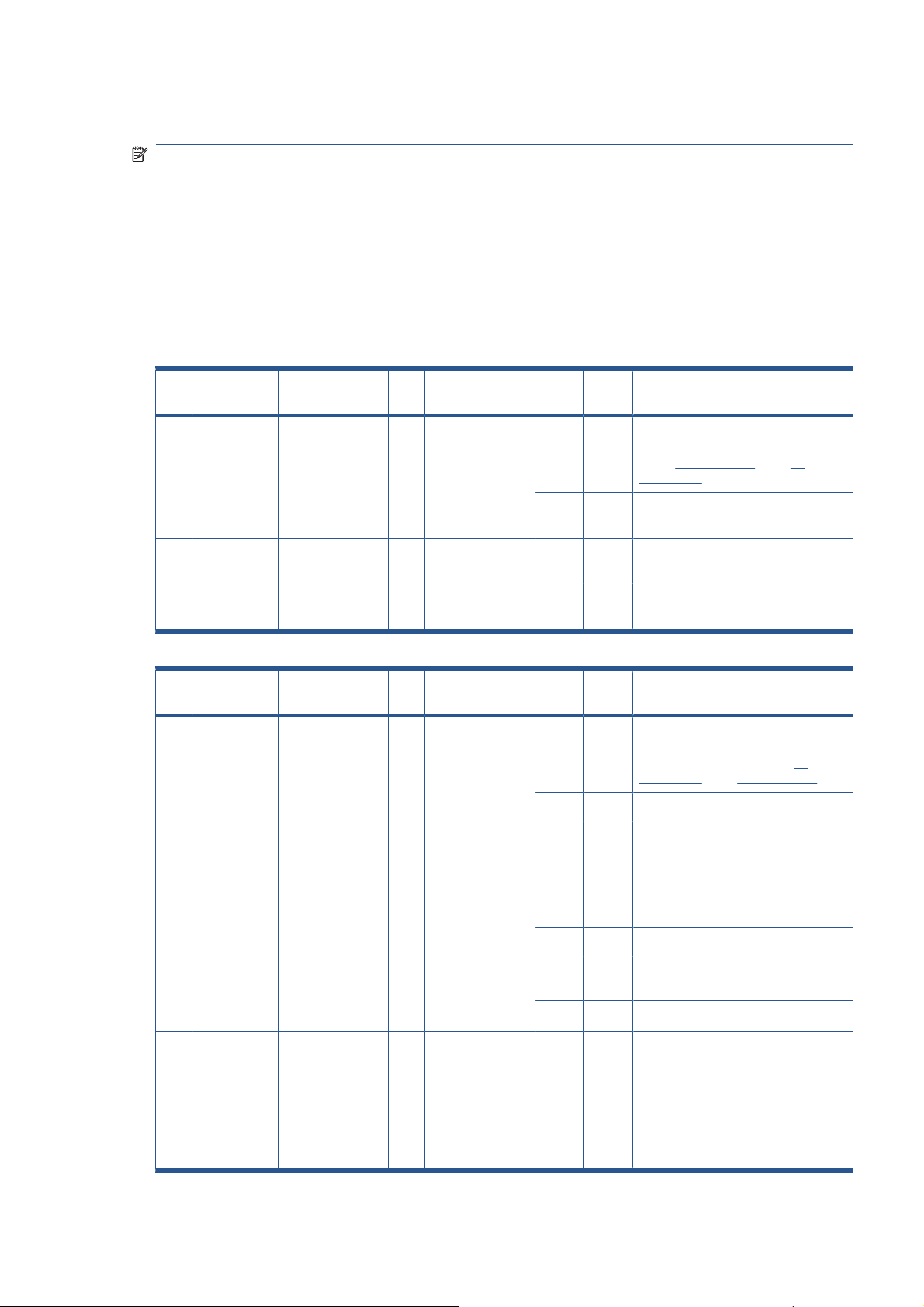
Troubleshooting print-quality and copy issues
P# Category Problem Q# Question Yes/NoC/T Solution
1 Copy
problem
2 Have you
P# Category Problem Q# Question Yes/NoC/T Solution
2 Copy
problem
2 Are the lines
The colors on one
side of the copy
do not
correspond to the
colors on the
other side of the
copy
I get thin lines of
wrong colors in
my copy
1 Have you cleaned
and calibrated
your scanner
recently?
upgraded the
system software
to the latest
version?
1 Are the lines
vertical and also
present in your
preview?
horizontal and
equally spaced?
No C Camera differences - The scanner
needs to be cleaned and calibrated
(see P
24 on page 17 and P25
on page 17)
Yes See Q2
No C Upgrade system software (use Update
Yes T Cameras need adjusting or the
Yes C Erase the parameter block and run the
No See Q2
Yes C Check printheads by starting
System DVD)
Camera Board replacing
scanner maintenance. Then clean and
calibrate the scanner (see P24
on page 17 and P25 on page 17)
printhead test on Printer. By using the
built-in test print function in the
Designjet Scan Copy application, you
can also get an idea whether the
Printer is performing OK
No See Q3
3 Are the lines
horizontal, but
irregular (maybe
only 1 line)?
4 Do you have a
great number of
regular spaced
lines very close to
each other and
restricted to one
side (1 camera)
only?
Yes C The lines could be caused by a data
error. Upgrade system software
No See Q4
Yes T You have a camera error. Replace
Camera Board
ENWW Troubleshooting print-quality and copy issues 7
Page 18
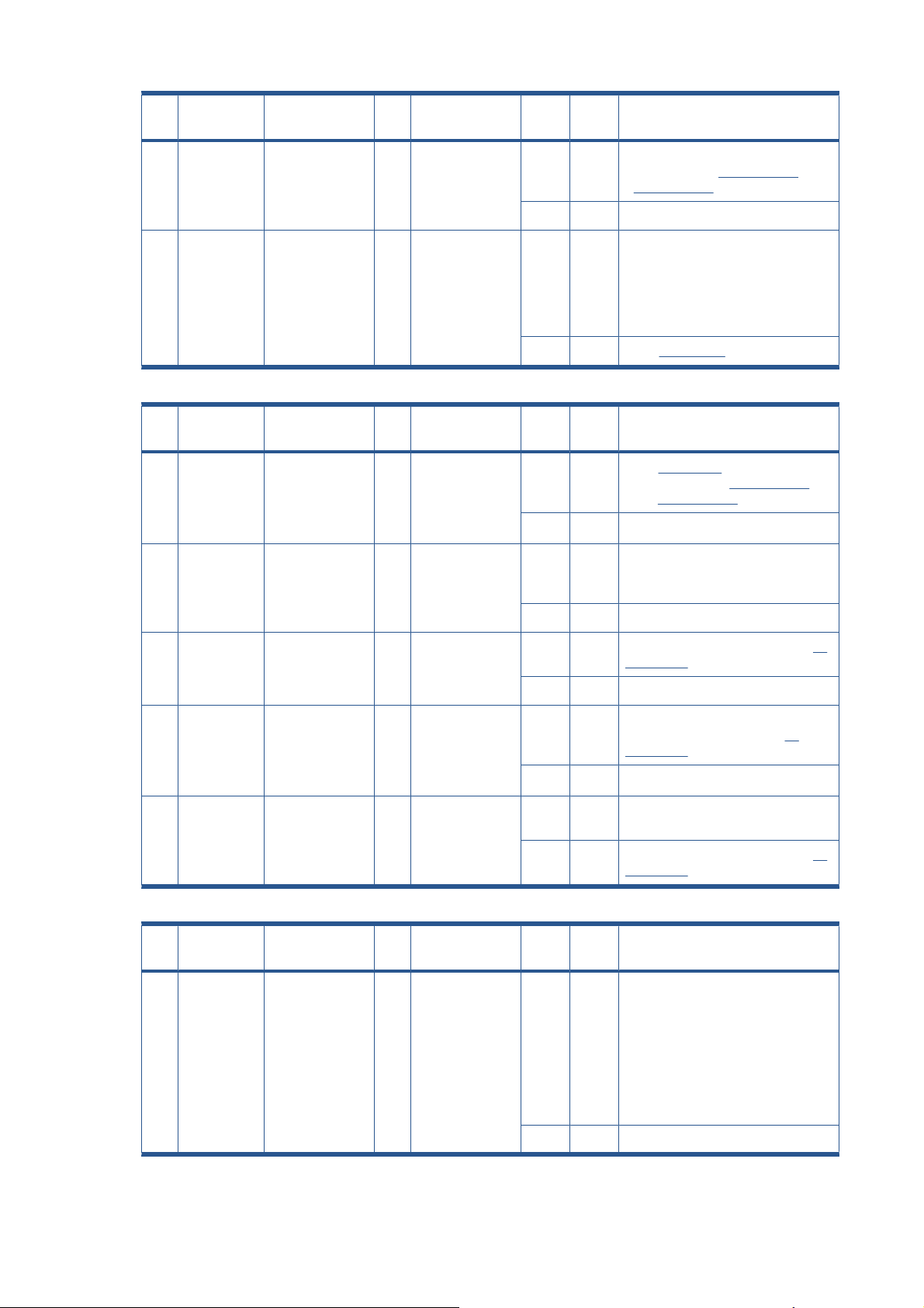
P# Category Problem Q# Question Yes/NoC/T Solution
3 Copy
problem
2 Are the lines
P# Category Problem Q# Question Yes/NoC/T Solution
4 Copy
problem
2 Do you use the
I get thick lines of
slightly wrong
colors in my copy
Some colors are
not the same
when I compare
the master print
with the copy
1 Are the lines
vertical and also
present in your
preview?
horizontal and
equally spaced?
1 Is the scanner
clean and
calibrated?
correct media
profile for the
actual media?
Yes C The scanner needs to be cleaned and
calibrated (see P
P
25 on page 17)
No See Q2
Yes C Check printheads by starting
No See P2 on page 7
No C See P1 on page 7. Clean and calibrate
Yes See Q2
No C If you are using e.g. Glossy Media for
Yes See Q3
printhead test on Printer. By using the
built-in test print function in the
Designjet Scan Copy application, you
can also get an idea whether the
Printer is performing OK
the scanner (see P
and P
25 on page 17)
this copy, the media profile selected
should also be for Glossy Media.
24 on page 17 and
24 on page 17
3 Is the media
profile valid?
4 Is the option 'Ink
5 Is the media you
P# Category Problem Q# Question Yes/NoC/T Solution
5 Copy
problem
Only a part of the
master print is
being copied
Printer Original'
set in accordance
with your
original?
are printing on the
same type as the
original?
1 Are you scanning
a thick original?
No C Create a new media profile (see P26
on page 17)
Yes See Q4
No C If original was printed using an Inkjet
Printer, set this option (see P
on page 17)
Yes See Q5
No C e.g. Use Glossy Media to reproduce a
Glossy original
Yes C Create a new media profile (see P26
on page 17)
Yes C Uncheck extended media handling
box in scanner settings (using
extended media will load the original
between both entry and exit rollers
before scanning - this means that you
will not have the start of the thick
original scanned. Also the scan speed
will be slower, and no "back - ups"/
reversing is allowed while scanning)
27
No See Q2
8 Chapter 1 Troubleshooting ENWW
Page 19

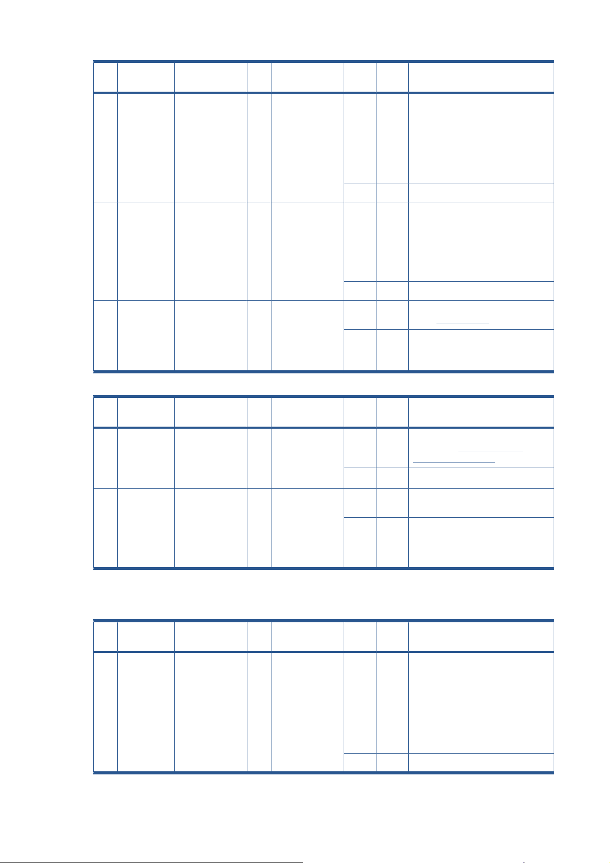
P# Category Problem Q# Question Yes/NoC/T Solution
2 Have you
selected 'Auto
size'?
3 Is the length too
short and the
width OK?
P# Category Problem Q# Question Yes/NoC/T Solution
6 Copy
problem
Which setting will
give me the best
result when
copying?
- - - C See section about media profile (P4).
Yes C The scanner needs to be cleaned (see
P
24 on page 17)
No See Q3
Yes C The problem may be with the Printer
(not able to print close to the edges) or
Panel PC (Hard Disk is full).
No C Check that the margins that are set are
not too big. Also check Scanner Media
Offsets
Use copy quality best. Choose the
correct Type of original ("Map" for
maps, "Photo" for photos, etc).
Eventually go to Original Setup to fine
adjust colors and sharpening. (See
also online help for more details button with "?" symbol)
P# Category Problem Q# Question Yes/NoC/T Solution
7 Copy
Problem
2 Is the Hard Disk
P# Category Problem Q# Question Yes/NoC/T Solution
8 Copy
problem
Nesting feature is
not working
The Collate Copy
function does not
work
1 Is the correct
printer selected?
close to being
full?
1 Is your Hard Disk
close to full?
No C Select the correct Printer
Yes See Q2
Yes C Free up some space, or try to run a
nesting job with only 2 or 3 small
pictures. If that works, see P
on page 17
No C Make sure that Nesting is set:
Select: Output Layout Nesting
optimized
Yes C Free up some space, or try to run a
collate job with a smaller picture.
No C Follow the step by step instructions in
the online help under Collate Copy.
27
ENWW Troubleshooting print-quality and copy issues 9
Page 20
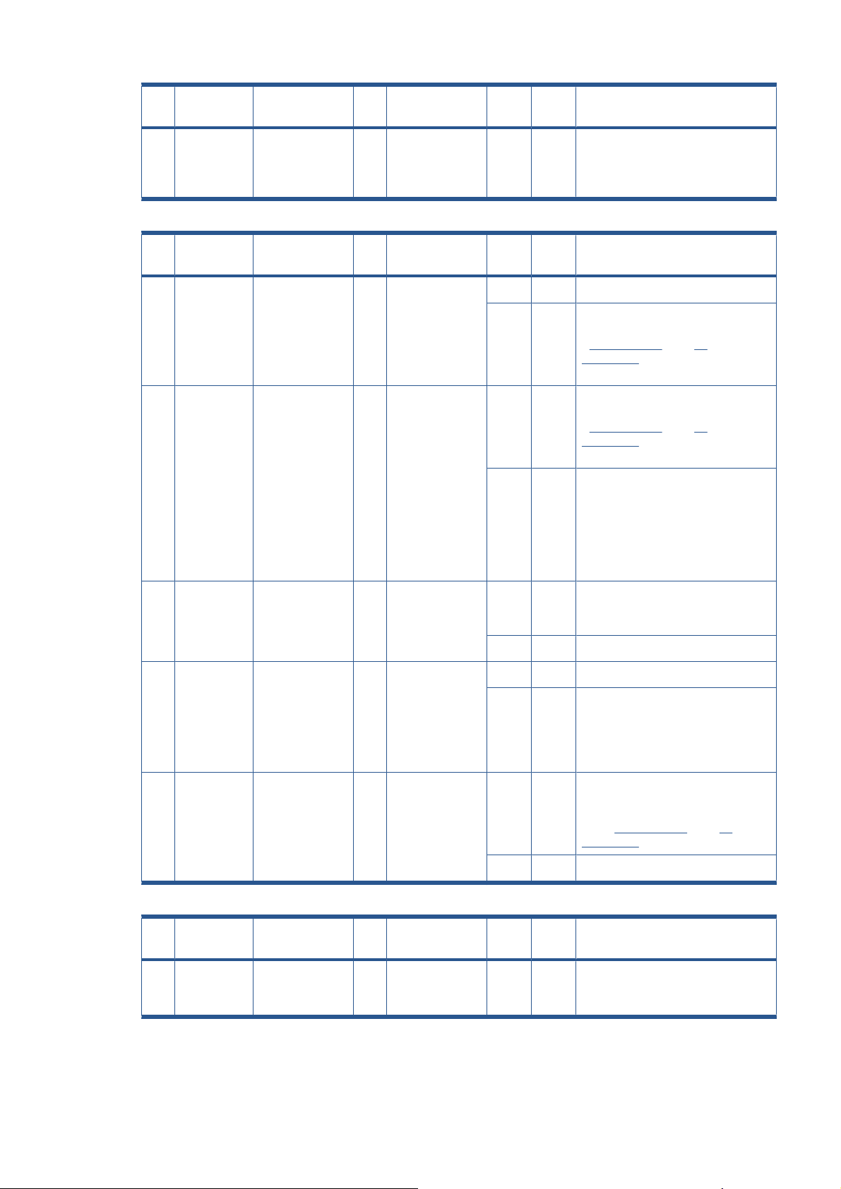
P# Category Problem Q# Question Yes/NoC/T Solution
9 Copy
problem
2 Are the lines not
3 Are the lines
The lines are not
accurate
1 Are the lines
wavy and
irregular?
sharp?
broken and the
errors situated in
a vertical column
between 2
columns?
Yes C/T C: The original could be curled or
crumpled. Try to flattten the original (in
case of very irregular waves there
could be a mechanical problem with
the scanner).
T: check motor and belt drive tension
according to TSM
No See Q2
Yes C/T C: Are you using the correct copy
method? Try sharpening. If sharpness
is different between Cameras, you
may have a Focus Problem.
T: Check focus of cameras with Focus
Adjustment Pattern.
No See Q3
Yes C You might have a visible stitching error
No C Check the dpi. In the case of too low
28 on page 17)
(see P
resolution, jagged diagonal lines will
appear.
P# Category Problem Q# Question Yes/NoC/T Solution
10 Copy
Problem
2 Have you
One side of the
preview is black
1 Have you
upgraded the
scanner firmware
to the latest
version?
upgraded the
system software
to the latest
version?
No C Upgrade scanner firmware to latest
Yes See Q2
No C Upgrade system software (use
Yes T Most likely a Camera Error. Perform
Troubleshooting general scanner issues
P# Category Problem Q# Question Yes/NoC/T Solution
11 Copy
problem
Only a part of the
master print is
being copied
1 Are you scanning
a thick original?
Yes C Uncheck extended media handling
version. See
Firmware on page 186.
System Recovery DVD).
the Manual Camera Adjustment (Test
9). Replace the Camera Board if
necessary.
box in scanner settings (using
extended media will load the original
between both entry and exit rollers
before scanning - this means that you
will not have the start of the thick
original scanned. Also the scan speed
will be slower, and no "back - ups"/
reversing is allowed while scanning).
Upgrade Scanner
No See Q2
10 Chapter 1 Troubleshooting ENWW
Page 21

P# Category Problem Q# Question Yes/NoC/T Solution
2 Have you
selected 'Auto
size'?
3 Is the length too
short and the
width OK?
P# Category Problem Q# Question Yes/NoC/T Solution
12 System Error What should I do
when the
program hangs?
1 Are you running a
copy job?
Yes C The scanner needs to be cleaned (see
P
24 on page 17)
No See Q3
Yes C The problem may be with the Printer
(not able to print close to the edges) or
Panel PC (Hard Disk is full).
No C Check that the margins that are set are
not too big. Also check Scanner Media
Offsets.
Yes C Making a copy takes a lot of resources
according to the settings. Wait till the
copy is done before performing
another action.
No Restart the system. If the problem is
coming back, run the System recovery
(see P
17 on page 13)
P# Category Problem Q# Question Yes/NoC/T Solution
13 File problem When I scan to
file, the file is very
big
2 Are you scanning
1 Are you scanning
in color?
in gray tones?
Yes C Scanning large drawings will generate
very big files. An A0 color drawing
scanned at 300 dpi will generate a file
size of approx. three Gigabytes when
scanned in an uncompressed format.
In order to reduce file size, select TIFF
- pack bits as format. You can reduce
size even more by selecting JPEG
format, but this format will reduce
picture quality.
No See Q2
Yes C Scanning large drawings will generate
big files. An A0 gray tone drawing
scanned at 300 dpi will generate a file
size of approx. 300 Mbytes when
scanned in an uncompressed format.
In order to reduce file size, select TIFF
- pack bits as format. You can reduce
size even more by selecting JPEG
format, but this format will reduce
picture quality.
No In order to reduce file size on scanned
B/W drawings, select TIFF group 4
compression.
ENWW Troubleshooting general scanner issues 11
Page 22

P# Category Problem Q# Question Yes/NoC/T Solution
14 File problem When I scan to
file my application
it cannot read the
file
P# Category Problem Q# Question Yes/NoC/T Solution
15 Network
Problem
P# Category Problem Q# Question Yes/NoC/T Solution
16 Scan to
network
(feature only
available in
T1100 MFP)
I cannot access
the system from
the network
I cannot access
network drivers
1 Did you get an
error message
when creating the
file?
1 Is the PC
connected to the
network?
1 With the Panel
PC connected to
the LAN, can you
access the Panel
PC from another
computer on the
network?
Yes C Check that you have enough disk
space and scan to file again, choosing
TIFF uncompressed as format
No C We only recommend to use the built-in
viewer for file viewing. Large format
drawing files may not load correctly in
other viewers due to file size. Try to
scan a smaller original (A4).
Yes C Do basic network troubleshooting.
No C Connect the PC to the Network.
Yes C Go to Q2
No C Check the network performance and
connection to the scanner Panel PC.
2 Is the folder of the
server you are
trying to map
already mapped
by another user in
the Panel PC?
3 Do you have
permission to
access and write
to the network
folder you are
trying to map?
4 Are you using the
correct user
name and
password?
Yes C Windows does not allow the same
server to be mapped by two different
users on one computer. Use the
access connection previously mapped
or delete the connection and map a
new access connection.
No C Go to Q3
Yes C Go to Q4
No C You cannot access this network folder.
Select a network folder for which you
have read and write permissions.
Yes C Try to map the network file from
another computer by selecting
Windows Explorer, Tools, Map
network drive. If you are able to map
the drive in this manner, you should
also be able to map through the Panel
PC.
No C Use the correct user name and
password.
12 Chapter 1 Troubleshooting ENWW
Page 23
P# Category Problem Q# Question Yes/NoC/T Solution
17 Recovery How and when is
the Recovery
DVD used?
P# Category Problem Q# Question Yes/NoC/T Solution
18 Scanner
Calibration
Problem
2 Error: Basic
Scanner
Maintenance did
not succeed
- - - C The recovery DVD is used if the
system needs to be reinstalled. Insert
the DVD in to the PC and reboot the
system.
1 Did any error
occur when
performing the
Scanner
Maintenance?
calibration was
performed. but
failed to stitch
scanner or
Could not find
horizontal line
or Could not
read bar lines
or Could not
recognize the
scanned IT8
picture.
Yes C See Q2
No C Clean the scanner and then run
Scanner Maintenance again (see
P24 on page 17 and P25
on page 17). If that does not help,
see Q5.
Yes C Clean the scanner and then run
Scanner Maintenance again (see
P
24 on page 17 and P25
on page 17). If that does not help,
see Q5.
No See Q3.
3 Error: Sheet not
recognized.
4 Error: No
5 Have you
P# Category Problem Q# Question Yes/NoC/T Solution
19 System error I cannot install my
application on the
system.
movement in
camera position
has been
detected during
vertical camera
alignment.
upgraded the
system software
to the latest
version?
- - - C The copy system is only meant to
Yes C Reinsert calibration sheet correctly
and run Scanner Maintenance again.
If that does not help, see Q5.
No See Q4.
Yes T Check the camera.
No See Q5.
No C Upgrade system software (use Update
System DVD). Clean the scanner and
then run Scanner Maintenance again
(see P
24 on page 17 and P25
on page 17).
Yes T Check the camera.
handle the factory installed software
and applications.
ENWW Troubleshooting general scanner issues 13
Page 24

P# Category Problem Q# Question Yes/NoC/T Solution
20 Updating How do I update
the system?
P# Category Problem Q# Question Yes/NoC/T Solution
21 Start-up
Problem
2 Does Panel PC
3 Does Panel PC
The system does
not power up
- - - C Insert the System Recovery DVD into
the DVD drive and reboot the Panel
PC.
1 Is the system
dead (no LEDs
are lit, the Panel
PC screen is
black, and no fannoise can be
heard)?
start with the
normal initial
screen?
start normally, but
the software does
not work?
Yes C 1. Check that all power switches on
the equipment are ON.
2. Check if there is power at the wall
outlet.
3. Check power cables between
wall outlet and the individual
units.
No See Q2.
Yes C See Q5.
No See Q3.
Yes C Reinstall system software
No See Q4
4 Is the Panel PC
dead (no fan
noise can be
heard and no
screen image
appears)?
5 Is the Scanner
dead (no fan
noise can be
heard and no
LEDs are lit)?
6 Does the scanner
hangup with all
LEDs lit?
P# Category Problem Q# Question Yes/NoC/T Solution
Yes T Troubleshoot the Panel PC.
No See Q5.
No See Q6.
Yes T Check, and if necessary replace:
1. Power Supply Unit
2. Driver Board
Yes T Try the following:
1. Erase parameter block
2. Update the system software
3. Replace the Main Board
No See P23 on page 15.
22 Mechanical
Problem
I cannot load the
original
1 Please try to load
a new piece of A4
paper at the
center of the
scanner. Does
this paper load?
Yes C You have a problem with your original.
Please check that paper edges are not
bent or curled in any way.
No See Q2.
14 Chapter 1 Troubleshooting ENWW
Page 25

P# Category Problem Q# Question Yes/NoC/T Solution
2 Can paper be
loaded by
pressing the
"Forward" key?
3 Does the Ready
P# Category Problem Q# Question Yes/NoC/T Solution
23 Error code I get an Error
Code, what do I
do?
LED turn ON
when activating
Original Sensor
(insert paper)?
- - - - Re-power the system, and check if the
Yes C See Q3.
No T Try replacing the following:
1. Driver Board
2. Power Supply Unit
3. Feed Motor
4. Main Board
No T Check, and if necessary replace:
1. Original Sensors
2. Main Board
Yes C Check the settings in the software for
media loading.
error code reappears. If it does, see
Q1.
1 Have you
P# Category Problem Q# Question Yes/NoC/T Solution
23a Error Code I still get an error
code, what do I
do?
upgraded the
system software
to the latest
version?
Does the
Diagnostic LED
(and, in some
cases also other
LEDs) blink?
No C Upgrade the system software by using
Yes C Lower Guide Plate to Normal position,
the System Recovery DVD). Check if
Error Codes reappears. If it does, see
P
23a on page 15.
start Preview Scan to obtain an Error
Code or check if WIDEsystem gives an
Error Code.
ENWW Troubleshooting general scanner issues 15
Page 26

P# Category Problem Q# Question Yes/NoC/T Solution
Error Code 100:
3002 to 3013
3019 to 3037
Error Code 100:
3014 to 3018
Error Code 100:
4003x and 4004x
Have you cleaned
the white
background and
glass plate, and
performed
Scanner
Maintenance?
Have you cleaned
the white
background and
glass plate, and
performed
Scanner
Maintenance?
1 Does the Lamp
light up?
Yes T Check Camera Adjustment. If
necessary, replace the Camera
Board.
No C See P24 on page 17 and P25
on page 17.
Yes T Try the following:
1. Upgrade the firmware
2. Check the Stitching Wire
3. Check Camera Adjustment
4. Replace Main Board
No C See P23 on page 15 and P25
on page 17.
No T Try replacing the following:
1. Lamp
2. Driver Board
3. Main Board
Yes See Q2.
2 Have you cleaned
the white
background and
glass plate, and
performed
Scanner
Maintenance?
Error Code 100:
500xx
Error Code 600xx 1 Is it Error Code
"No scanner
found"
1 Have you
performed
Scanner
Maintenance?
600xx
1 Does the scanner
start normally?
2 Are the interface
cables (USB or
FireWire)
properly
connected to the
scanner and the
Panel PC?
3 Have you run the
System Recovery
DVD?
Yes See complete list.
No C See P24 on page 17 and P25
on page 17.
No C See P24 on page 17 and P25
on page 17.
Yes T Replace Main Board
Yes T Replace Interface Board
No C See P23 on page 15.
Yes C See Q2.
Yes C See Q3.
Yes T 1. Replace Interface Cable
2. Replace Interface Board
16 Chapter 1 Troubleshooting ENWW
Page 27

P# Category Problem Q# Question Yes/NoC/T Solution
24 Cleaning How do I clean
the scanner?
P# Category Problem Q# Question Yes/NoC/T Solution
25 Color
Calibration
P# Category Problem Q# Question Yes/NoC/T Solution
26 Media
Validation
How do I color
calibrate the
scanner?
What is media
validation? How
do I validate?
- - - C Clean the Glass Plate on both sides
with mild detergent, and wipe
thoroughly with a lint-free cloth until
dry. Check for scratches. Deep
scratches on the glass plate or
background platen means
replacement of the part.
1 Do you have the
correct and "as
new" scanner
maintenance
sheet for the
scanner?
— — - C If the validate feature is chosen, a new
Yes C Clean scanner (see P24 on page 17).
Insert the scanner maintenance sheet.
Start scanner maintenance. The
process is automatic and will also
include stitching.
No C Get Correct/New Scanner
Maintenance Sheet.
color patch sheet is printed and can be
scanned for validation. In this way it
can be determined whether the
produced color map has passed.
P# Category Problem Q# Question Yes/NoC/T Solution
27 Ink Printer
Original
P# Category Problem Q# Question Yes/NoC/T Solution
28 Visible
stitching
Errors
What is Ink
Printer Original?
What is a visible
stitching error?
- — - C When the original has been printed on
an Inkjet printer this option should be
enabled.
- - - C A visible stitching error appears
typically as a column of broken lines
between 2 cameras. Normally it can be
solved by running Scanner
Maintenance, which will perform an
automatic stitching adjustment. With
some curled or creased/crumpled
originals it is necessary to straighten
out the original to prevent it from lifting
from the glass plate. With thick
originals it can be necessary to adjust
the stitching (stitching used for thick
originals only, set this in scanner
setup). A visible stitching error should
not be confused with the error
message Error 32 - Could not stitch
Camera A and B.
ENWW Troubleshooting general scanner issues 17
Page 28

Troubleshooting Specific Scanner Issues
P# Category Problem Q# Question Yes/NoC/T Solution
29 Vertical lines
(possible
dust
problem)
P# Category Problem Q# Question Yes/NoC/T Solution
30 Firmware You are receiving
P# Category Problem Q# Question Yes/NoC/T Solution
The image has a
vertical, white or
black line, which
could be caused
by dust. To verify
that the line is
caused by dust,
preview the
image and
inspect the
preview using the
viewing section
buttons.
firmware-related
errors.
- - - C Perform Scanner Maintenance:
Cleaning and Camera Alignment.
Using Test 20 from SCANtest 6 may
help to identify dusty/ dirty areas.
- - - C Try upgrading the firmware version.
Upgrade Scanner Firmware
See
on page 186.
31 Stepper
Motor
P# Category Problem Q# Question Yes/NoC/T Solution
32 Lamp The lamp does
The Stepper
Motor does not
work.
not work.
- - - C Try the following:
1. Use Test 6: Motor Test to check
the functionality of the Stepper
Motor.
2. Replace the Driver Board.
3. Replace the Stepper Motor.
- - - C Try the following:
1. Reseat the lamp cartridge.
2. Ensure that the Driver Board is
connected to the power supply
unit.
3. Ensure that the lamp sensor and
the Driver Board are functioning
correctly.
18 Chapter 1 Troubleshooting ENWW
Page 29

P# Category Problem Q# Question Yes/NoC/T Solution
33 Skewing There is a
skewing problem
P# Category Problem Q# Question Yes/NoC/T Solution
34 Media
Loading
The media connot
be loaded or
there are other
media loading
problems.
- - - C Try the following:
1. Ensure that the Guide Plate is
closed and latched.
2. Replace the Guide Plate.
3. Clean the rollers with isopropyl
alcohol.
4. Replace the rollers.
- - - C Try the following:
1. Check the Original Sensor
(green LED when loading
media), or use Test 4: Original-
Sensor Test to check the
functionality of the sensor.
2. Use Test 6: Motor Test to check
the functionality of the Stepper
Motor.
P# Category Problem Q# Question Yes/NoC/T Solution
35 Fan The fan is not
working
P# Category Problem Q# Question Yes/NoC/T Solution
36 Software You are
experiencing
problems with the
software
- - - C Try the following:
1. Ensure that the fan is correctly
connected.
2. If the fan is connected and still
doesn’t work, replace the Driver
Board or the fan.
3. If the fan and driver board are
working correctly, the problem
could be related to the NTC
Sensor.
- - - C Try the following:
1. Use the System Recovery DVD
to reload the software.
2. After reloading the software, set-
up the system on the network
again (if necessary).
3. If the problems persist, run the
System Recovery DVD again,
and delete the user’s files
(press F12).
ENWW Troubleshooting Specific Scanner Issues 19
Page 30
P# Category Problem Q# Question Yes/NoC/T Solution
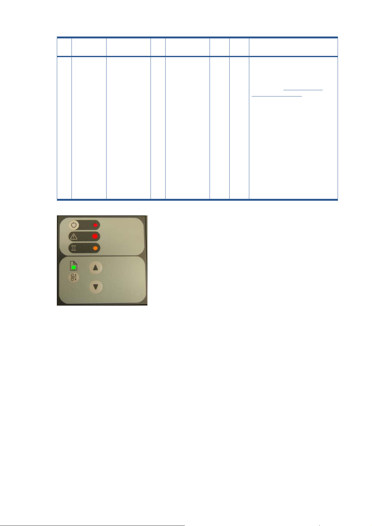
37 Firmware All of the LEDs in
the scanner’s
front panel are
flashing when you
turn on the
scanner (as
shown in the
image below),
indicating that
printer firmware
needs to be
upgraded.
NOTE: This
describes a
different situation
than when the
scanner is turned
on in special boot
mode, in which
the LEDs also
flash.
- - - C The most probable reason for this
situation is that the last firmware
upgrade attempt was not successful.
To remedy this situation, upgrade the
firmware (see
Firmware on page 186).
NOTE: Before launching the
firmware upgrade utility, verify that the
scanner is connected directly to the
touchscreen by the FireWire cable,
and then press the rescan bus button.
The scanner will not detect the
necessary connection without the use
of the FireWire.
Upgrade Scanner
Cleaning the Scanning Area
The following parts must be cleaned using a soft lint-free cloth and a mild, streak-free, cleaning
detergent. Alternatively, the parts may be cleaned without the use of cleaning detergents by using a
damp micro-fibre cleaning cloth (soak the cloth with water and wring until damp):
Main scanner cover. Clean the main scanner cover to ensure that no dust is introduced into the
●
scanning area when you scan an original.
White Background Plate on the Guide Plate
●
The Glass Plate. If you clean both sides, be very careful not to touch the Stitching Wire (located
●
under the Glass Plate) out of position. Do not use solvents, as this may dissolve the paint used for
the black masks on the Glass Plate. Do not recommend that customers clean the underside of the
glass plate; it should only be cleaned by an HP support technician.
The Mirrors. It is necessary to remove the Mirror Chassis to get access to the Mirrors for cleaning.
●
The Camera Adjustment must be checked and if necessary readjusted after the replacement of
the Mirror Chassis.
20 Chapter 1 Troubleshooting ENWW
Page 31

NOTE: The mirrors are normally "Out of Focus", therefore small dust particles on the mirrors will not
deteriorate the scanning result.
The Feed Rollers. These may be cleaned with a damp micro-fibre cleaning cloth.
●
Once all these procedures have been completed, the scanner will be ready to work correctly.
The Cleaning Procedure
When cleaning any part of the scanning area DO NOT use abrasives, acetone, benzene or fluids that
contain these chemicals. Do not spray liquids directly onto the scanner glass plate or anywhere else in
the scanner.
1. Turn the scanner power off.
2. Disconnect the scanner power cable.
3. Open the Guide Plate by pushing down on the left and right locking levers and flip it upwards to
expose the scan area.
4. Gently wipe the Glass Plate. Clean the glass with a lint-free cloth and a mild, streak-free, glass
cleaner.
ENWW Cleaning the Scanning Area 21
Page 32

5. Dry the glass completely using a separate clean, dry lint-free cloth like the one provided with the
maintenance kit.
6. Clean the white background assembly. Wipe the white metal area with a lint-free cloth and a mild,
streak-free, glass cleaner.
7. Clean the platen rollers. Wipe the rollers with a lint-free cloth and a mild, streak-free, glass cleaner.
22 Chapter 1 Troubleshooting ENWW
Page 33

8. Dry the platen and rollers completely using a separate clean, dry lint-free cloth.
9. Close the Guide Plate.
10. Use the dust sheet to protect the Scanner when not in use.
CAUTION: Ensure that the scanner is turned off before covering it with the dust sheet. The
scanner will overheat if covered while turned on.
Troubleshooting Specific Panel PC Problems
Power failure
●
Boot up fails
●
LCD/Inverter fails
●
No backlight and no display
●
With backlight but no display
●
How to check the voltage of the Power Supply Unit in the PanelPC.
●
How to check the voltage of the Inverter PCA in the PanelPC
●
The HDD fails
●
DDR DRAM fails
●
ENWW Troubleshooting Specific Panel PC Problems 23
Page 34

DVD-ROM fails
●
The CD/DVD is stuck in the DVD-ROM and can’t be ejected out
●
The following section is related to the PanelPC and it’s related components.
Power failure
If the power has been turned on, and there is no message on the screen, try the following:
Make sure the power cord is correctly connected.
●
Plug the power cord to another power outlet.
●
The DVD-ROM indicator lights should flash.
●
The system fan should start up if there is power in the PanelPC. If not, replace the PSU. See
●
Supply Unit (rev A) on page 153.
Boot up fails
The PanelPC issues a series of beeps which can be used to identify which part is failing.
One short beep: No error during POST (Power on Self-Test).
●
One long beep followed by two short beeps: Video initial error.
●
One long beep followed by nine short beeps: BIOS Bootblock error.
●
Single long beep repeatedly: DRAM error.
●
LCD/Inverter fails
The failure of the LCD display can be divided into two issuses, the PanelPC has no backlight and no
display, or the PanelPC has the backlight but there is no display. Use the two troubleshooting flow charts
to solve the problem:
No backlight and no display
Power
24 Chapter 1 Troubleshooting ENWW
Page 35

With backlight but no display
How to check the voltage of the Power Supply Unit in the PanelPC.
With power on, measure the red pins and the yellow pins of the power connector.
Output voltage of the red pins should be 5V±5%.
●
Output voltage of the yellow pins should be 12V±5%.
●
ENWW Troubleshooting Specific Panel PC Problems 25
Page 36

Only for rev. A scanners: Output voltage of the yellow pins should be 12V±5%.
●
Only for rev. B scanners: Output voltage of the orange pin should be +3.3V.
How to check the voltage of the Inverter PCA in the PanelPC
With power on, measure pin 1 of the Inverter PCA input and output connectors.
Output voltage should be between 600V and 710V (typical value is 640V).
●
Input voltage should be 12V±10%.
●
The HDD fails
The HDD is running, and the system configuration has identified the HDD’s ID while booting up. Try the
following:
Set the type of hard disk to AUTO in STANDARD CMOS SETUP.
●
Reconnect the cable between HDD and main board.
●
Change the HDD. See
●
The HDD is not running, and the system configuration can not identify the HDD’s ID while booting up.
Try the following:
Reconnect the cable between HDD and main board.
●
Change the cable between HDD and main board.
●
Change the HDD. See
●
26 Chapter 1 Troubleshooting ENWW
Hard Disk Drive (rev A) on page 142.
Hard Disk Drive (rev A) on page 142.
Page 37

DDR DRAM fails
If the computer repeatedly makes a long beep, and the display is blank when you power on, this indicates
a DDR DRAM error, replace the DDR DRAM. See
DVD-ROM fails
The DVD-ROM indicator light is on when you switch on. Try the following:
Check the possible damage on the cable between DVD-ROM and main board.
●
The DVD-ROM indicator light is off when power up and the screen show no message of any DVD-
●
ROM installed.
Check for DVD-ROM auto detection in the BIOS setup:
●
Procedure to do this: In the BIOS setup, select standard CMOS features, set all IDE/SATA
detections ( ie Primary master, Primary slave, secondary master, secondary slave ) to AUTO.
Reconnect the cable between DVD-ROM and main board.
●
DRAM PCA on page 139.
Replace the DVD-ROM. See
●
DVD Drive on page 140.
ENWW Troubleshooting Specific Panel PC Problems 27
Page 38

The CD/DVD is stuck in the DVD-ROM and can’t be ejected out
Push a pin into the hole at the right side of the DVD-ROM eject button.
●
Image fails
Follow the steps in the flowchart below to quickly check an image problem:
Touch screen fails
Follow the steps in the flowchart below to quickly check if the touch screen fails:
28 Chapter 1 Troubleshooting ENWW
Page 39

Touch screen is working but can’t control the cursor
Try the following:
Run the calibration program.
●
Check that the cable between the LCD controller and the LCD is connected in the correct position.
●
Replace the LCD controller. See
●
Replace the LCD. See
●
LCD on page 134.
LCD Controller PCA (rev A) on page 145.
Preventive Maintenance Kit for HP Designjet Scanners
The following scanner messages are shown on the touch screen. They are all shown in the "scanner
messages" window that pops up automatically if a message should be notified to the user, and the
window can also be recalled manually by pressing the progress bar area of JETimage.
User warnings:
Scanner Maintenance has not been run for 30 days.
●
Lamp quality fails. Filter should be replaced at the same time.
●
The lamp quality is electrically monitored and the warning appears after 4000 hours of usage. The
scanner maintenance warning appears when scanner maintenance has not been performed for 30 days.
However, the frequency with which scanner maintenance should be performed depends on scanner
usage.
ENWW Preventive Maintenance Kit for HP Designjet Scanners 29
Page 40

2 System Error Codes
System Error Codes for the Scanner Only on page 31
●
Error Codes for the JetImage Software RIP on page 39
●
Error Messages for the Touch Screen on page 45
●
30 Chapter 2 System Error Codes ENWW
Page 41

System Error Codes for the Scanner Only
Introduction
The following pages contain a list of system error codes and their respective descriptions and
recommended corrective actions. Only try one recommended action at a time and check if the error
code has disappeared.
If you have an error code which is not documented in this Service Manual or you have an error which
you cannot resolve, then report the error to the HP Response Center or the nearest HP Support Office.
When reporting the error, have the following information ready:
Model and Serial Number of the scanner.
●
Which firmware revision the printer and the scanner is using.
●
SW version.
●
The complete error number.
●
ScanDump of Light Profiles.
●
Error Codes Displayed on the Operator Panel
A flashing Diagnostic Indicator indicates an error condition. The error can be identified by an error code
number being displayed on the Touch Screen and/or by the following combination of flashing indicators
on the Operator Panel:
Diagnostic LED
(A)
Flashing Flashes once OFF Correction of camera A failed
Flashing Flashes twice OFF Correction of camera B failed
Flashing Flashes 3 times OFF Correction of camera C failed
Flashing Flashes 4 times OFF Correction of camera D failed
Flashing OFF Flashes once Error on Main PCA
Flashing OFF Flashes twice Error on Camera Board
Flashing OFF Flashes 3 times Invalid Scanner ID setting
Flashing OFF Flashes 4 times Error on Interface Board
Flashing Flashing Flashing Scanner is in Boot Mode
Flashing OFF OFF See Error Codes
OFF Flashing Red Guideplate assembly is not in the right position, to solve it
Wait LED (B) Ready LED (C) Error Description
press down the guideplate to move it to the original position
(step 0: 2mm/0.8").
ENWW System Error Codes for the Scanner Only 31
Page 42

The Software Modules
The first set of numbers in the error code refer to a part of the Scanner software or the Scanner.
Software Modules Comments/Notes
51 - Scanner API Low level scanner control library. All scanner communication goes
52 - Image Format Library Printer and file formatting. All printing and file read/write is formatted/
53 - Copy Engine The central processing engine in the (JETimage) software.
54 - Closed Loop Calibration Color Management math library that calculates the media profiles.
55 - Test Software Scanner Maintenance / SCANtest.
56 - Jetimage container All user interface and business logic except for Scanner
57 - WIDEsystem (WS) Scanner surveillance utility
100 - Scanner Mechanical part of the Scanner.
55-203
Cause Solution
though this API.
decoded by this library.
Maintenance / SCANtest and WIDEsystem.
No movement in camera position has been detected during
vertical camera alignment. Check the camera.
100-3051
Cause Solution
The scanner’s ID switch has been set to an invalid value.
Please change switch setting.
Try the following:
Check that all the cables are connected correctly to the
●
Cameras and the Camera Boards.
Run SCANtest 6, test 9 or 11 and check each Camera
●
Motor functions correctly.
Try the following:
Check that all the cables are connected correctly to the
●
Main Electronics Board, Control Panel Board in the Right
Cover.
Run SCANtest 6, test 7. See
●
Test on page 5.
Replace the Right Cover. See
●
on page 68.
Replace the Main Electronics Board. See
●
Electronics Board on page 93.
Test 7: Complete Hardware
Right Cover
Main
32 Chapter 2 System Error Codes ENWW
Page 43

100-3054
Cause Solution
Unable to write to EEPROM/FLASH Try the following:
Check that all the cables are connected correctly to the
●
Main Electronics Board.
Run SCANtest 6, test 7. See
●
Test on page 5.
Replace the Main Electronics Board. See
●
Electronics Board on page 93.
100-3056
Cause
Flash Error: Unable to erase Try the following:
100-3057
Cause Solution
Solution
Check that all the cables are connected correctly to the
●
Main Electronics Board.
Run SCANtest 6, test 7. See
●
Test on page 5.
Replace the Main Electronics Board. See
●
Electronics Board on page 93.
Test 7: Complete Hardware
Main
Test 7: Complete Hardware
Main
Flash Error: Unable to program Try the following:
Check that all the cables are connected correctly to the
●
Main Electronics Board.
Run SCANtest 6, test 7. See
●
Test on page 5.
Replace the Main Electronics Board. See
●
Electronics Board on page 93.
100-3058
Cause
SCU Board Error Try the following:
Solution
Check that all the cables are connected correctly to the
●
Main Electronics Board.
Run SCANtest 6, test 7. See
●
Test on page 5.
Replace the Main Electronics Board. See
●
Electronics Board on page 93.
Test 7: Complete Hardware
Main
Test 7: Complete Hardware
Main
ENWW System Error Codes for the Scanner Only 33
Page 44

100-3059
Cause Solution
Camera Board, Error Try the following:
To find out which board has an error, Run SCANtest 6,
●
test 7 and check the performance of each camera.
Check that all the cables are connected correctly to the
●
Cameras Boards.
Run SCANtest 6, test 9 (
●
on page 5) and check the Camera Board.
Replace the Camera Board. See
●
on page 86.
Replace the Main Electronics Board. See
●
Electronics Board on page 93.
100-3061
Cause Solution
There is a problem with the Interface Board. Try the following:
Check that the Interface Board is correctly installed.
●
Run SCANtest 6, test 7. See
●
Test on page 5.
Replace the Interface Board. See
●
on page 95.
100-20086
Test 9: Camera Adjustment
Camera Board
Main
Test 7: Complete Hardware
Interface Board
Cause Solution
Unable to communicate with the ATAC Controller Board. Try the following:
Check that all the cables are connected correctly to the
●
ATAC Board and the Main Electronics Board.
Run SCANtest 6, test 7. See
●
Test on page 5.
Replace the ATAC Board. See
●
Board on page 99.
Replace the Main Electronics Board. See
●
Electronics Board on page 93.
Test 7: Complete Hardware
Elevation Motor Driver
Main
34 Chapter 2 System Error Codes ENWW
Page 45

100-20219
Cause Solution
There is a problem with one of the Fans. Try the following:
Check that all the cables are connected correctly to the
●
Fans.
Check that all the cables are connected correctly to the
●
Driver Board.
Perform the Driver Board Communication Test. See
●
Driver Board Communication Test on page 185.
Replace the Fan. See
●
Replace the Driver Board. See
●
on page 90.
100-20221
Cause Solution
There is a problem with the Driver Board. Try the following:
Check that all the cables are connected correctly to the .
●
Perform the Driver Board Communication Test. See
●
Driver Board Communication Test on page 185.
Run SCANtest 6, test 7. See
●
Test on page 5.
Replace the Driver Board. See
●
on page 90.
Replace the Main Electronics Board. See
●
Electronics Board on page 93.
Fan on page 92.
Driver Board
Test 7: Complete Hardware
Driver Board
Main
100-4003x/4004x
Cause
Error on Camera Board. Use the list below to identify the failing
Camera Board.
Camera A: 40035, 40039, 40043, 40047
●
Camera B: 40036, 40040, 40044, 40048
●
Camera C: 40037, 40041, 40045, 40049
●
Camera D: 40038, 40042, 40046, 40050
●
Solution
Try the following:
Run SCANtest 6, test 7 to verify the error.
●
Check that all the cables are connected correctly.
●
Run SCANtest 6, test 9 and check the light profiles.
●
See
Test 9: Camera Adjustment on page 5.
Erase the Parameter Blocks.
●
Run the Scanner Maintenance. See
●
Maintenance on page 179.
Replace the Camera Board. See
●
on page 86.
Scanner
Camera Board
ENWW System Error Codes for the Scanner Only 35
Page 46

100-4017x/4018x
Cause Solution
Unable to calibrate a camera. Use the following list to identify
the failing camera.
Camera A: 40170, 40174, 40178, 40182, 40186
●
Camera B: 40171, 40175, 40179, 40183, 40187
●
Camera C: 40172, 40176, 40180, 40184, 40188
●
Camera D: 40173, 40177, 40181, 40185, 40189
●
100-40075
Cause Solution
Camera Board, FPGA CB status error. Try the following:
Try the following:
Erase the parameter block and perform scanner
●
maintenance. See
Check that all cables are connected correctly to the
●
Camera Board and the Main Electronics Board.
Switch Mode Power Supply.
●
Run SCANtest 6, test 9. See
●
Adjustment on page 5.
Replace the Main Electronics Board. See
●
Electronics Board on page 93.
Replace the failing Camera Board. See
●
on page 86.
Check that all the cables are connected correctly to the
●
Cameras Boards.
Scanner Maintenance on page 179.
Test 9: Camera
Main
Camera Board
Replace the Camera Board. See
●
on page 86.
Replace the Main Electronics Board. See
●
Electronics Board on page 93.
100-40076
Cause
Camera Board, FPGA CB done error. Try the following:
Solution
Check that all the cables are connected correctly to the
●
Cameras Boards.
Run SCANtest 6, test 9. See
●
Adjustment on page 5.
Replace the Camera Board. See
●
on page 86.
Run SCANtest 6, test 7. See
●
Test on page 5.
Replace the Main Electronics Board. See
●
Electronics Board on page 93.
Camera Board
Main
Test 9: Camera
Camera Board
Test 7: Complete Hardware
Main
36 Chapter 2 System Error Codes ENWW
Page 47

100-40084
Cause Solution
Camera Board, Camera Cables disconnected. Try the following:
Check that all the cables are connected correctly to the
●
Cameras Boards.
Run SCANtest 6, test 9. See
●
Adjustment on page 5.
Replace the Camera Board. See
●
on page 86.
Run SCANtest 6, test 7. See
●
Test on page 5.
Replace the Main Electronics Board. See
●
Electronics Board on page 93.
100-4013x
Cause Solution
Unable to calibrate an undefined Camera. Try the following:
Erase the parameter block and perform scanner
●
maintenance. See Scanner Maintenance on page 179.
Switch Mode Power Supply.
●
Check that all the cables are connected correctly to the
●
Cameras Boards.
Run SCANtest 6, test 9. See
●
Adjustment on page 5.
Test 9: Camera
Camera Board
Test 7: Complete Hardware
Main
Test 9: Camera
Replace the Camera Board. See
●
on page 86.
Run SCANtest 6, test 7. See
●
Test on page 5.
Replace the Main Electronics Board. See
●
Electronics Board on page 93.
100-500xx
Cause Solution
Error on the Main Electronics Board. Try the following:
Check that all the cables are connected correctly to the
●
Main Electronics Board.
Run Scanner Maintenance. See
●
on page 179.
Upgrade the Scanner Firmware.
●
Run SCANtest 6, test 7. See
●
Test on page 5.
Replace the Main Electronics Board. See
●
Electronics Board on page 93.
Camera Board
Test 7: Complete Hardware
Main
Scanner Maintenance
Test 7: Complete Hardware
Main
ENWW System Error Codes for the Scanner Only 37
Page 48

100-50199
Cause Solution
Incorrect Main Electronics Board and Camera Board. Please
validate the combination for this scanner.
100-600xx
Cause Solution
Communications Interface Error. Try the following:
Try the following:
Check that all the cables are connected correctly to the
●
Cameras Boards.
Update the firmware.
●
Run SCANtest 6, test 9. See
●
Adjustment on page 5.
Replace the Camera Board. See
●
on page 86.
Run SCANtest 6, test 7. See
●
Test on page 5.
Replace the Main Electronics Board. See
●
Electronics Board on page 93.
Check that all the cables are connected correctly to the
●
Main Electronics Board and the Interface Board is
correctly installed.
Test 9: Camera
Camera Board
Test 7: Complete Hardware
Main
Run SCANtest 6, test 7. See
●
Test on page 5.
Replace the Camera Board. See
●
on page 86.
Replace the Main Electronics Board. See
●
Electronics Board on page 93.
Test 7: Complete Hardware
Camera Board
Main
38 Chapter 2 System Error Codes ENWW
Page 49

Error Codes for the JetImage Software RIP
-19 When combining thick media handling (paper guide in extended position) with auto size detection, the size
detection must be done separately by running a preview scan before the final copy or scan operation.
Cause
When combining thick media handling (paper guide in
extended position) with auto size detection, the size detection
must be done separately by running a preview scan before the
final copy or scan operation.
-16 error reading the RIP gray balance file.
Cause Solution
If current media profile specifies to use CSV-file in the RIP gray
balance and the file is not found.
-14 Unable to reserve the scanner.
Cause Solution
Unable to reserve the scanner. Check and see if any other application is using the scanner.
-13 Unable to rename the folder.
Solution
Try the following:
Run a preview scan before the final copy or scan
●
operation.
Perform the copy or scan to file instead.
●
Either disable the use of gray balance or attempt to create the
file again.
Cause Solution
Unable to rename the folder. Occurs during file browsing operations, usually due to a share
issue.
-12 Unable to delete the folder.
Cause
Unable to delete the folder (occurs during file browsing
operations, typically if a folder is shared).
-11 The folder must be empty.
Cause
The folder must be empty (occurs during file browsing
operations).
Solution
Close all the applications and try again.
Solution
Check that the folder is empty before deleting it.
ENWW Error Codes for the JetImage Software RIP 39
Page 50

-9 The currently selected printer is not installed in the system.
Cause Solution
The windows printer driver for the currently selected printer is
not found.
-6 No scanner selected or selected scanner not present.
Cause Solution
No scanner selected or selected scanner not present. If the
scanner was turned Off during application start-up.
-2 No media profile selected for current printer.
Cause Solution
No media profile selected for current printer. Prepare a Media Profile before performing the operation.
-1 No printer selected.
Try the following:
Check that the printer driver is installed.
●
Install the printer driver if not already installed.
●
Try the following:
Check that the scanner is turned On.
●
Check that the scanner is selected.
●
Cause Solution
No printer selected. Select a printer. A printer must be configured in the application
before trying to print.
02 Invalid scan coordinates. The paper frame was placed fully outside the scan image.
Cause Solution
Invalid scan coordinates. The paper frame was placed fully
outside the scan image.
06 Not enough disk space for spool file.
Cause Solution
Not enough disk space for spool file. Make sure that the environment TEMP (or secondary TMP)
08 The scanner is currently on standby. Please press the soft power button on the scanner to activate it.
Cause Solution
Try repositioning the paper frame so that it covers some of the
scannable area.
points to a folder with plenty of space.
The scanner is currently on standby. Press the soft Power button on the scanner to activate it.
40 Chapter 2 System Error Codes ENWW
Page 51

00003 Scanning invalid size of area requested for scanning.
Cause Solution
Negative scan-width specified. Reselect the scan area and try again.
01003 Error printing colorsheet.
Cause
Error printing colorsheet. Try the following:
01013 Error detecting index-mark.
Cause
Skew: Error detecting the index mark. Try the following:
01014 Sheet bad aligned.
Cause Solution
Solution
Check the printer to make sure it is switched ON and
●
connected to the scanner.
Try printing a test print to make sure that the printer is
●
working.
Solution
Try restarting the system.
●
If the problem persists, view the scandump.tif file for
●
further diagnosis.
Sheet badly aligned. Try the following:
Reinsert the sheet, making sure that it is straight and at
●
the right position.
If the problem persists, view the scandump.tif file for
●
further diagnosis.
01015 Error detecting left margin.
Cause
Error detecting the left margin of the sheet. Try the following:
Solution
Try reinserting the sheet.
●
If the problem persists, view the scandump.tif file for
●
further diagnosis.
ENWW Error Codes for the JetImage Software RIP 41
Page 52

01016 Error detecting right margin.
Cause Solution
Error detecting the right margin of the sheet. Try the following:
Try reinserting the sheet.
●
If the problem persists, view the scandump.tif file for
●
further diagnosis.
01017 Error reading colorsheet.
Cause Solution
Error reading the colorsheet. The end of the sheet is reached
before expected.
01018 CLC aborted.
Cause
The Close Loop Calibration (CLC) has been aborted. The user has cancelled the color map operation.
01019 Wrong insert position.
Cause Solution
The sheet has been inserted in the wrong position. Try the following:
01020 Can’t find top of sheet.
Check that the correct colorsheet is being used.
Solution
Reinsert the sheet, making sure that it is at the right
●
position.
If the problem persists, view the scandump.tif file for
●
further diagnosis.
Cause Solution
The top of the sheet couldn’t be found. Reinsert the sheet, making sure that it is at the right position.
01021 Can’t find bottom of sheet.
Cause
The bottom of the sheet couldn’t be found. Reinsert the sheet, making sure that it is at the right position.
01022 Does not correspond to this version or clc.dll.
Cause
Incorrect version of the language resource dll. Install the correct version of the language resource dll.
Solution
Solution
42 Chapter 2 System Error Codes ENWW
Page 53

02004 Unable to open device for reading.
Cause Solution
Unable to open the device for reading. Check that the device (file) is available.
02005 Unable to open device for writing.
Cause
Unable to open the device for writing. Check that the device (file or printer) is available.
02006 Unable to read from device.
Cause Solution
Unable to read from the device. Try the operation again.
02007 Unable to write to device.
Cause Solution
Unable to write to the device. Try the operation again.
02013 Destination already exists.
Cause Solution
Destination already exists. Try the operation again with a different file name.
Solution
03008 Device not available.
Cause Solution
Scanner not found. Try the following:
Check that the scanner is turned ON.
●
Check the connection to the scanner.
●
13496 The scanner is initializing or warming up.
Cause Solution
The scanner is initializing. This happens if you try to scan too quickly after powering ON
the scanner. Wait a short while and then try scanning again.
17977 Media is present in scanner, but command was aborted by user.
Cause Solution
User interfered with the scanner. Try the operation again.
ENWW Error Codes for the JetImage Software RIP 43
Page 54

17980 Paper jam.
Cause Solution
Paper jam. Check rollers and mechanical paper detectors for any paper
jam. Once paper jam is cleared, try the operation again.
44 Chapter 2 System Error Codes ENWW
Page 55

Error Messages for the Touch Screen
BIOS ROM checksum error - system halted.
Cause Solution
Error during initialization. Reboot the system and enter the BIOS setting. Load Setup
Default and save the BIOS setting.
CMOS battery failed.
Cause Solution
The battery life is approximately three years before it requires
replacement.
CMOS checksum error - defaults loaded.
Cause Solution
Error detected in the CMOS. Reboot the system and enter the BIOS setting. Load Setup
Display switch is set incorrectly
Cause Solution
Problem found with the Touch Screen. Connect the Touch Screen to a CRT Monitor and check the
Hard Disk install failure.
Cause
Replace the CMOS Battery.
Default and save the BIOS setting.
resolution setting for the display. If the CRT Monitor is working
well then it seems there is an LCD problem. Return the Panel
PC to Repair Center for further tests.
Solution
No Hard Disk detected, error related to Hard Disk Drive. Try the following:
In the BIOS setup select Standard CMOS Features and
●
check if the IDE/SATA detection method is set to AUTO
(password to access the BIOS is bigcoco)?
If Yes: In Advanced BIOS features, set HDD to first
◦
boot device.
If No: Choose auto for all IDE/SATA detection.
◦
Check if HDD can be detected in the boot-up system
●
configuration table:
If Yes: check the boot up files in HDD, recover it if
◦
necessary.
If No: replace HDD.
◦
ENWW Error Messages for the Touch Screen 45
Page 56

Primary master hard disk fail.
Cause Solution
No Hard Disk detected, error related to Hard Disk Drive. Try the following:
In the BIOS setup select Standard CMOS Features and
●
check if the IDE/SATA detection method is set to AUTO
(password to access the BIOS is bigcoco)?
If Yes: In Advanced BIOS features, set HDD to first
◦
boot device.
If No: Choose auto for all IDE/SATA detection.
◦
Check if HDD can be detected in the boot-up system
●
configuration table:
If Yes: check the boot up files in HDD, recover it if
◦
necessary.
If No: replace HDD.
◦
Secondary master hard disk fail.
Cause Solution
No Hard Disk detected, error related to Hard Disk Drive. Try the following:
In the BIOS setup select Standard CMOS Features and
●
check if the IDE/SATA detection method is set to AUTO
(password to access the BIOS is bigcoco)?
If Yes: In Advanced BIOS features, set HDD to first
◦
boot device.
If No: Choose auto for all IDE/SATA detection.
◦
Check if HDD can be detected in the boot-up system
●
configuration table:
If Yes: check the boot up files in HDD, recover it if
◦
necessary.
If No: replace HDD.
◦
46 Chapter 2 System Error Codes ENWW
Page 57

Primary slave hard disk fail.
Cause Solution
No Hard Disk detected, error related to Hard Disk Drive. Try the following:
In the BIOS setup select Standard CMOS Features and
●
check if the IDE/SATA detection method is set to AUTO
(password to access the BIOS is bigcoco)?
If Yes: In Advanced BIOS features, set HDD to first
◦
boot device.
If No: Choose auto for all IDE/SATA detection.
◦
Check if HDD can be detected in the boot-up system
●
configuration table:
If Yes: check the boot up files in HDD, recover it if
◦
necessary.
If No: replace HDD.
◦
Secondary slave hard disk fail.
Cause Solution
No Hard Disk detected, error related to Hard Disk Drive. Try the following:
In the BIOS setup select Standard CMOS Features and
●
check if the IDE/SATA detection method is set to AUTO
(password to access the BIOS is bigcoco)?
If Yes: In Advanced BIOS features, set HDD to first
◦
boot device.
If No: Choose auto for all IDE/SATA detection.
◦
Check if HDD can be detected in the boot-up system
●
configuration table:
If Yes: check the boot up files in HDD, recover it if
◦
necessary.
If No: replace HDD.
◦
Floppy disk(s) fail.
Cause Solution
No Floppy Disk detected. Try the following:
Check if the Floppy Disk Drive cable is connected
●
correctly, reconnect the cable if necessary.
Replace the Floppy Disk Drive.
●
ENWW Error Messages for the Touch Screen 47
Page 58

Floppy disk(s) fail (40).
Cause Solution
No Floppy Disk detected. Try the following:
Check if the Floppy Disk Drive cable is connected
●
correctly, reconnect the cable if necessary.
Replace the Floppy Disk Drive.
●
Floppy disk(s) fail (80).
Cause Solution
No Floppy Disk detected. Try the following:
Check if the Floppy Disk Drive cable is connected
●
correctly. Reconnect the cable if necessary.
Replace the Floppy Disk Drive.
●
Keyboard error or no keyboard present.
Cause Solution
No keyboard has been detected. Try the following:
Check if the Keyboard is connected correctly. Reconnect
●
the cable if necessary.
Replace the Keyboard.
●
The driver is not ready.
Cause Solution
The system cannot read from the DVD drive. Try the following:
Eject the DVD currently in the DVD drive and place it into
●
a different DVD drive. Can the DVD be read in the other
DVD drive?
If Yes: Replace the DVD drive.
◦
If No: Replace the DVD; it could be damaged.
◦
Memory test fail.
Cause Solution
Memory test has failed. Try the following:
Re-install the SDRAM and check if the problem is solved:
●
If Yes: There was a poor connection between the
◦
Main Board and the SDRAM Memory Module.
If No: Replace the SDRAM Memory Module.
◦
48 Chapter 2 System Error Codes ENWW
Page 59

3 Parts and Diagrams
Copier Stand & Touch Screen on page 50
●
Copier Covers on page 52
●
Top Assemblies on page 53
●
Inside Guide Plate on page 54
●
Drive Assemblies on page 55
●
Camera Components and Fan on page 56
●
Electronic Boards on page 57
●
Panel PC on page 57
●
Panel PC Cabinet Components (Part 1) on page 58
●
Panel PC Cabinet Components (Part 2) on page 60
●
Miscellaneous items on page 61
●
ENWW 49
Page 60

Copier Stand & Touch Screen
Number
in photo
CQ653-67002 1 x Stand (PC not included)
1 Q1277-60037 1 x Top Bar with Guide
1 Q6685-60004 1 x x Top Bar
2 Q1277-60038 2 x x Leg
2 Q6685-60005 2 x x x Leg
3 Q1277-60039 2 x x Feet (includes Castors)
3 Q6685-60006 2 x x x Feet (includes Castors)
4 Q1277-60040 1 x x Rear Bar
4 Q6685-60007 1 x x x Rear Bar
5 Q1277-60041 1 x x Arm
5 Q6685-60008 1 x Arm
5 Q6713-60006 1 x x Arm
6 - 1 x x x Touch Screen
HP part
number
Quantity Scanner model Description / Comments
820
MFP
(see also Panel PC on page 57 and the two following sections)
45x0
ScannerHDScanner
T11x0
MFP
T1200
HD MFP
7 Q1277-60042 1 x x x x x Bracket
Copier Stand & Touch Screen HD Scanner & T1200 HD MFP Copier Stand & Touch
Screen (no keyboard)
50 Chapter 3 Parts and Diagrams ENWW
Page 61

Number
in photo
HP part
number
Quantity Scanner mode l Description / Comments
820
MFP
45x0
ScannerHDScanner
T11x0
MFP
T1200
HD MFP
8 820 MFP: Q6685-60002, 4500 Scanner: Q1277-60026, 4520
Scanner: CM770-60002, HD Scanner: CQ654-67001, T1100 MFP: Q6713-60005,
T1120 HD MFP: CK841-60003, T1200 HD MFP: CQ653-67001
9 Q1277-60020 1 x x x x x Paper Guides
10 Q1277-60044 1 x Keyboard Shelf
10 Q6685-60010 1 x x Keyboard Shelf
11 Q1277-60045 1 x x x Keyboard English
11 Q1277-60046 1 x x x Keyboard French
11 Q1277-60047 1 x x x Keyboard Italian
11 Q1277-60048 1 x x x Keyboard German
11 Q1277-60049 1 x x x Keyboard Spanish
11 Q1277-60050 1 x x x Keyboard Portuguese
11 Q1277-60051 1 x x x Keyboard Chinese
11 Q1277-60052 1 x x x Keyboard Taiwanese
11 Q1277-60053 1 x x x Keyboard Japanese
Q6685-60003 1 x x Assembly Kit (screws,
Q6713-60013 1 x Assembly Kit (screws,
Nameplate
etc.)
etc.)
CQ653-67004 1 x Assembly Kit (screws,
etc.)
Copier Stand & Touch Screen HD Scanner & T1200 HD MFP Copier Stand & Touch
Screen (no keyboard)
ENWW Copier Stand & Touch Screen 51
Page 62

Copier Covers
Number
in photo
1 Q1277-60023 1 x x x x x Top Cover
2 Q1277-60021 1 x x x x Left Cover
2 Q6713-60008 1 x End Cover, Left
3 820 MFP: Q6685-60012, 4500 Scanner: Q1277-60022, 4520
4 Q1277-60024 1 x x Top Profile
4 Q6713-60003 1 x x x Top Profile
5 Q1277-60029 1 x x x x FireWire Connector Cover
5 Q6713-60010 1 x Connector Cover
6 Q1277-60028 1 x x x x Fluorescent Lamp Access
6 Q6713-60009 1 x Lamp Cartridge Cover
HP part
number
Scanner: CM770-60001, HD Scanner: CQ654-67013, T1100 MFP: Q6713-60007,
T1120 HD MFP: CK841-60004, T1200 HD MFP: CQ653-67005
Quantity Scanner model Description / Comments
820
MFP
45x0
ScannerHDScanner
T11x0
MFP
T1200
HD MFP
Right Cover (incl. Front
Panel)
Cover
52 Chapter 3 Parts and Diagrams ENWW
Page 63

Top Assemblies
Number
in photo
1 Q1277-60025 1 x x Guide Plate Assembly
1 Q6713-60004 1 x x x Guide Plate Assembly
2 Q1277-60014 1 x x x x x Glass Plate
3 Q1277-60027 1 x x x x x White Background
4 Q1277-60013 1 x x x x x Fluorescent Lamp
HP part
number
Quantity Scanner mode l Description / Comments
820
MFP
45x0
ScannerHDScanner
T11x0
MFP
T1200
HD MFP
Assembly
ENWW Top Assemblies 53
Page 64

Inside Guide Plate
Number
in photo
1 Q1277-60005 1 x x x x x MDA Board
2 Q1277-60008 1 x x x x x Opto Interrupter media
3 Q1277-60011 1 x x Elevation Motor
3 Q6713-60002 1 x x x Elevation Motor
HP part
number
Quantity Scanner model Description / Comments
820
MFP
45x0
ScannerHDScanner
T11x0
MFP
T1200
HD MFP
sensor
54 Chapter 3 Parts and Diagrams ENWW
Page 65

Drive Assemblies
Number
in photo
1 Q1277-60018 1 x x x x x Roller Shields
2 Q1277-60015 1 x x x x x Rollers
3 Q1277-60009 1 x x x x x Stepper Motor Assembly
4 Q1277-60016 1 x x x x x Belt
5 Q1277-60091 1 x x x x x Media Sensors Kit
6 Q1261-60008 1 x x x x x Stitching Wire
HP part
number
Quantity Scanner mode l Description / Comments
820
MFP
45x0
ScannerHDScanner
T11x0
MFP
T1200
HD MFP
ENWW Drive Assemblies 55
Page 66

Camera Components and Fan
Number
in photo
1 Q1277-60002 2 x x x Camera Board
1 CQ654-67002 2 x x Camera Board, CBMA
2 Q1277-60010 1 x x x x x Camera Motor
3 Q1277-60012 1 x x x x x Fan
4 Q1277-60033 1 x x x Complete Camera
4 CQ654-67004 1 x x Complete Camera
5 Q1277-60034 1 x x x Complete Camera (with
5 CQ654-67005 1 x x Complete Camera (with
Camera Components and Fan HD Scanner & T1200 HD MFP Camera Components and
HP part
number
Quantity Scanner model Description / Comments
820
MFP
45x0
ScannerHDScanner
Fan
T11x0
MFP
T1200
HD MFP
(without Motor)
(without Motor), CBMA
Motor)
Motor), CBMA
56 Chapter 3 Parts and Diagrams ENWW
Page 67

Electronic Boards
Number
in photo
1 Q1277-60090 1 x x x Scanner PSU
1 CQ654-67011 1 x x Scanner PSU, SKYNET
2 Q1277-60001 1 x x x x x Driver Board
3 Q6713-60001 1 x x x Main Board
3 CQ654-67015 1 x x Main Board
4 Q1277-60004 1 x x x x x Interface Board
Electronic Boards HD Scanner & T1200 HD MFP Electronic Boards
HP part
number
Quantity Scanner mode l Description / Comments
820 45x0 HD T11x0 T1200
Panel PC
The Panel PC is composed of the Touch Screen, the LCD Controller and the Inverter.
ENWW Electronic Boards 57
Page 68

Ref in
photo
HP part
number
Qty Scanner model Description /
820 45x0 HD (rev
A)
HD (rev
B)
T11x0 T1200
(rev A)
T1200
(rev B)
Comments
1 CQ654-670
08
CQ654-670
1
18
1 x x x x x LCD Controller +
Touch Screen (with
1 x x
Inverter, numbered 2
below)
Panel PC Cabinet Components (Part 1)
Ref in
photo
1 Q1277-60065 1 x x x x x System Fan
58 Chapter 3 Parts and Diagrams ENWW
HP part
number
Qty Scanner model Description /
820 45x0 HD (revA)HD (revB)T11x0 T1200
(rev
A)
T1200
(rev B)
Comments
Page 69

1 CQ654-67024 1 x x System Fan
2 Q1277-60057 1 x x x x x Power Supply Unit
2 CQ654-67019 1 x x Power Supply Unit
1
3 Q1277-60056 1 x x x
Hard Disk Drive
1
3 CQ654-67007 1 x x x x x Hard Disk Drive
3 CQ654-67028 1 x x Hard Disk Drive
5 Q1277-60061 1 x x x x x CPU Fan
5 CQ654-67021 1 x x CPU Fan
6 Q1277-60058 1 x x x x x SDRAM Memory
Module
6 CQ654-67020 1 x x SDRAM Memory
Module
11
Available only until inventory depletion
NOTE: The LCD Controller (4) is supplied with the Touch Screen (see Panel PC on page 57).
NOTE: In the HD & T1200 HD MFP scanners (rev A), the Hard Disk Drive (3) is mounted upside-down
and has an IDE to SATA converter.
Electronic Boards HD Scanner & T1200 HD MFP Electronic Boards (rev A)
HD Scanner & T1200 HD MFP Electronic Boards (rev B)
ENWW Panel PC Cabinet Components (Part 1) 59
Page 70

Panel PC Cabinet Components (Part 2)
Ref in
photo
1 Q1277-600541 x x x
1 CQ654-670061 x x x x x Main board
1 CQ654-670161 x x Main board
2 Q1277-600551 x x x x x DVD-ROM
2 CQ654-670291 x x DVD-ROM
3 Q1277-600621 x x x x x CPU
3 CQ654-670221 x x CPU
11
Available only until inventory depletion
Electronic Boards HD Scanner & T1200 HD MFP Electronic Boards (rev B)
HP part
number
Qty Scanner model De scriptio n /
820 45x0 HD
(rev A)
HD (rev
B)
T11x0 T1200
(rev A)
T1200
(rev B)
Comments
Main board
1
1
60 Chapter 3 Parts and Diagrams ENWW
Page 71

Miscellaneous items
HP part number Quantity Scanner model Description / Comments
820
MFP
Q1277-60030 1 x x x x x Service Patterns (includes the
Q1277-60031 1 x x x Optical Pattern, 3-camera
CQ654-67003 1 x x Optical Pattern, 4-camera
CQ654-67014 1 x x Returnable Optical Pattern, 4-
Q1277-60032 1 x x x x x Calibration Sheet
Q1261-60044 1 x x x x x Stylus
Q1277-60035 1 x x x Harness Assembly
CQ654-67012 1 x x Harness Assembly
Q1261-60042 1 x x x x x A2 Scan Cover
Q1277-60019 1 x x x x x Dust Cover 40"
Q1277-60092 1 x x x x x Scanner FireWire Cable
Q1277-60084 1 x x x x x Adjustment Tools for ATAC
45x0
ScannerHDScanner
T11x0
MFP
T1200
HD MFP
focus pattern and the
calibration sheet)
518 dpi
600 dpi
camera 600 dpi
Sensors
Q1277-60093 1 x x x x x Panel PC cable harness
For HD & T1200 rev B the
Panel PC cable harness part
number is: CQ654-67025
Q1277-60094 1 x x x x x Panel PC power switch button
Q1276-60003 1 x x x x Printer FireWire cable
Q1277-60095 1 x x A0 transparent sheet
Q1277-60097 1 x x Gas spring guide plate (150N
A)
Q1277-60098 1 x Paper basket
ENWW Miscellaneous items 61
Page 72

HP Part Number Part Description
CQ654-67012 and Q1277-60035 Harness SV,
Q1277A
Q1277-60093 and CQ654-67025 Panel PC
Cable harnesses
Scanner Cables Kit
●
●
●
●
●
●
●
●
●
●
●
●
Stepper Motor Cable
Camera Cable
LMF – Lamp Cartridge Cable
SUx – MDx Cable
SMPS – LMF Cable
LMF – SUx – IMx (Power) Cable
LMF – SUx Cable
Cameras Cables
Keyboard Cable
Panel PC cables
HDD Cable
DVD Cable
MB to Touch Controller Cable
●
●
●
Touch Cont. to Touch Scr. Cable
LCD Cable
Inverter Cable
62 Chapter 3 Parts and Diagrams ENWW
Page 73

4 Removal and Installation
Introduction on page 64
●
Safety Precautions on page 64
●
Electrostatic Discharge (ESD) Precautions on page 65
●
Required Tools on page 65
●
Top Cover on page 66
●
Left Cover on page 67
●
Right Cover on page 68
●
Rear Cover on page 72
●
Top Profile on page 73
●
Guide Plate on page 76
●
Guide Plate on page 80
●
Glass Plate on page 81
●
Entry Roller Shield on page 82
●
Exit Roller Shield on page 83
●
Camera Motor on page 84
●
Camera Lens Assembly on page 85
●
Camera Board on page 86
●
Power Supply Board on page 88
●
Driver Board on page 90
●
Fan on page 92
●
Main Electronics Board on page 93
●
Interface Board on page 95
●
Stepper Motor on page 96
●
Fluorescent Lamp on page 98
●
Elevation Motor Driver Board on page 99
●
Elevation Motor on page 102
●
Entry Roller on page 105
●
ENWW 63
Page 74

Exit Roller on page 110
●
Exit Roller on page 118
●
Entry Media Sensor on page 119
●
Exit Media Sensor on page 120
●
Belt on page 121
●
Bottom Cover on page 123
●
Mirror Chassis on page 126
●
Stitching Wire on page 128
●
White Background Assembly on page 130
●
PanelPC on page 131
●
Open Cabinet on page 131
●
Screen Bezel on page 134
●
LCD on page 134
●
Back Plate (rev A scanners) on page 136
●
CPU Cooling Fan on page 137
●
CPU on page 138
●
DRAM PCA on page 139
●
DVD Drive on page 140
●
Hard Disk Drive (rev A) on page 142
●
LCD Controller PCA (rev A) on page 145
●
Inverter PCA on page 146
●
HDD/DVD Deck (rev A) on page 147
●
Main PCA (rev A) on page 149
●
Power Supply Unit (rev A) on page 153
●
System Fan on page 156
●
Introduction
This chapter is a step-by-step guide to the removal and installation of the key components in the product.
You may find it useful to tick off the steps as they are performed. Use the illustration at each procedure
to identify the parts referred to in the text.
The procedures appear in order of removal. So the whole product can be stripped down by starting at
the beginning of this chapter and working through the subsequent procedures.
Safety Precautions
Review WARNING and CAUTION instructions before you service the product. Follow these warnings
and cautions for your protection and to avoid damaging the product.
64 Chapter 4 Removal and Installation ENWW
Page 75

NOTE: Serious shock hazard leading to death or injury may result if you do not take the following
precautions:
Ensure that the AC power outlet (mains) has a protective earth (ground) terminal.
Switch off the printer, the scanner, and the PC, and then disconnect them from the power source prior
to performing any maintenance.
Prevent water or other liquids from running onto electrical components or circuits, or through openings
in the module.
Electrostatic Discharge (ESD) Precautions
To prevent damage to the product circuits from high-voltage electrostatic discharge (ESD):
1. Do not wear clothing that is subject to static build-up.
2. Do not handle integrated circuits (ICs) in carpeted areas.
3. Do not remove an IC or a printed circuit assembly (PCA) from its conductive foam pad or conductive
packaging until you are ready to install it.
4. Ground (earth) your body while disassembling and working on the Scanner. This can be done by
touching any metallic part of the Scanner.
5. After removing a cover from the Scanner, attach an earthing (ground) lead between the PCA
common and earth ground. Touch all tools to earth ground to remove static charges before using
them on the Scanner.
6. After removing any PCA from the Scanner, place it on a conductive foam pad or into its conductive
packaging to prevent ESD damage to any ICs on the PCA.
Required Tools
The following tools are required to disassemble and repair the Scanner:
Screwdriver (0.8 x 5)
●
1.3 mm Allen Key
●
1.5 mm Allen Key
●
5.5 mm Wrench
●
6 mm Wrench
●
7 mm Wrench
●
8 mm Wrench
●
13 mm Wrench
●
Torx 5 L shape
●
Torx 6 L shape
●
Torx 8 L shape
●
Torx 9 L shape
●
Torx 10 L shape
●
Torx 20 L shape
●
ENWW Electrostatic Discharge (ESD) Precautions 65
Page 76

Philips PH1 Screw driver
●
Philips PH2 Screwdriver
●
Top Cover
Removal
NOTE: Switch off the printer, the scanner, and the PC, and then disconnect them from the power
source prior to performing any maintenance.
1. Open the Guide Plate.
2. Remove two T20 screws along the lower edge of the Top Cover.
3. Pull the front part of the Top Cover away from the Scanner in order to release the upper part of the
Top Cover.
66 Chapter 4 Removal and Installation ENWW
Page 77

4. Lift up the Top Cover and remove from the Scanner.
Left Cover
Removal
NOTE: Switch off the printer, the scanner, and the PC, and then disconnect them from the power
source prior to performing any maintenance.
1. Remove the Top Cover See Top Cover on page 66.
2. Remove four T10 screws that secure the Left Cover from underneath.
3. Remove two T20 screws that secure the Left Cover from the side.
ENWW Left Cover 67
Page 78

4. Remove one T20 screw that secures the Left Cover from the top.
5. Remove the Left Cover from the Scanner.
Right Cover
Removal
NOTE: Switch off the printer, the scanner, and the PC, and then disconnect them from the power
source prior to performing any maintenance.
1. Remove the Top Cover See Top Cover on page 66.
2. Remove the Fluorescent Lamp Access Cover.
68 Chapter 4 Removal and Installation ENWW
Page 79

3. Press the metal tab to release the Flourescent Lamp.
4. Slide out the Fluorescent Lamp.
5. Remove the Operator Panel Cable from a cable clamp.
ENWW Right Cover 69
Page 80

6. Disconnect the Operator Panel Cable from the Main Electronics PCA.
7. Remove four T10 screws that secure the Right Cover from underneath.
8. Remove two T20 screws that secure the Right Cover from the top.
70 Chapter 4 Removal and Installation ENWW
Page 81

9. Remove two T20 screws that secure the Right Cover from the side.
10. Pass the Operator Panel Cable through an access hole.
11. Remove the Right Cover from the Scanner.
ENWW Right Cover 71
Page 82

Rear Cover
Removal
NOTE: Switch off the printer, the scanner, and the PC, and then disconnect them from the power
source prior to performing any maintenance.
1. Remove five T10 screws (and one washer) that secure the Rear Cover to the rear of the Scanner.
2. Lift up and release the left side of the metal shelf.
3. Lift up and release the right side of the metal shelf.
72 Chapter 4 Removal and Installation ENWW
Page 83

4. Remove the metal shelf.
5. Remove five T10 screws (and one washer) that secure the Rear Cover to the lower edge of the
Scanner.
6. Remove the Rear Cover from the Scanner.
Top Profile
Removal
ENWW Top Profile 73
Page 84

NOTE: Switch off the printer, the scanner, and the PC, and then disconnect them from the power
source prior to performing any maintenance.
1. Lift the Top Profile so that you can access the rule.
2. Remove the rule from the front of the Guide Plate.
3. Close the Top Profile.
74 Chapter 4 Removal and Installation ENWW
Page 85

4. Remove four T10 screws that secure the front of the Top Profile to the Guide Plate.
5. Lift up the Top Profile of the Guide Plate.
6. Use an Allen key (size 1.5) to loosen the screw at the left side of the scanner.
ENWW Top Profile 75
Page 86

7. Slide the retainer bar from its fitting to release the left side of the Top Profile.
8. Slide the Top Profile slightly toward the left to release the right side of the Top Profile.
9. Remove the Top Profile.
Guide Plate
Removal
NOTE: Switch off the printer, the scanner, and the PC, and then disconnect them from the power
source prior to performing any maintenance.
1. Remove the Top Cover See Top Cover on page 66.
2. Remove the Right Cover
3. Remove the Top Profile
76 Chapter 4 Removal and Installation ENWW
See Right Cover on page 68.
See Top Profile on page 73.
Page 87

4. Detach the Guide Plate Cable from the Main Electronics Board (J20) in the Guide Plate.
5. Tie a cable or a piece of string (the yellow cable in the photo) to the Guide Plate Cable to facilitate
passing the Guide Plate Cable through the access hole.
6. Pass the cable through the access hole.
ENWW Guide Plate 77
Page 88

7. Pass the cable through the ferrite core and through the access hole in the side of the chassis.
8. After passing the Guide Plate Cable through the access hole and the ferrite core, detach the cable
you used to assist in pulling it through.
9. Remove the Guide Plate Cable from the cable clamps.
78 Chapter 4 Removal and Installation ENWW
Page 89

10. The Guide Plate must be in a raised position. Manually rotate the motor wheel toward you (as
shown in the photo) until it no longer turns.
11. Remove one T20 screw that secures the left side of the Guide Plate.
12. Remove one T20 screw that secures the right side of the Guide Plate.
ENWW Guide Plate 79
Page 90

13. Remove the Guide Plate from the Scanner.
Guide Plate
Installation
NOTE: Switch off the printer, the scanner, and the PC, and then disconnect them from the power
source prior to performing any maintenance.
1. On the right side of the scanner, position the brass piece into its fitting as shown in the photo, and
then fit the right side of the cover into place.
2. On the left side of the scanner, position the brass piece into its fitting as shown in the photo, and
then fit the left side of the cover into place.
80 Chapter 4 Removal and Installation ENWW
Page 91

3. When closing the cover, be sure to place the gray lever (1) between the pin (2) and the brass piece
(3).
4. To complete the installation of the Guide Plate, follow steps 1-12 from the Guide Plate removal
procedure in reverse order.
Glass Plate
Removal
NOTE: Switch off the printer, the scanner, and the PC, and then disconnect them from the power
source prior to performing any maintenance.
1. Open the Guide Plate.
2. Carefully lift up the rear of the Glass Plate at both ends.
ENWW Glass Plate 81
Page 92

3. Remove the Glass Plate from the Scanner.
NOTE: Always clean the new glass before installation.
Entry Roller Shield
Removal
NOTE: Switch off the printer, the scanner, and the PC, and then disconnect them from the power
source prior to performing any maintenance.
1. Remove the Top Cover See Top Cover on page 66.
2. Use a size 6 wrench to loosen the eight guide pins on the front side of the Entry Roller Shield.
3. Loosen eight screws on the front side of the Entry Roller Shield.
82 Chapter 4 Removal and Installation ENWW
Page 93

4. Gently remove the Entry Roller Shield from the Scanner. Be careful NOT to bend it or damage it
while removing.
Exit Roller Shield
Removal
NOTE: Switch off the printer, the scanner, and the PC, and then disconnect them from the power
source prior to performing any maintenance.
1. Remove the Guide Plate See Guide Plate on page 80.
2. Remove the Rear Cover
3. Use a size 6 wrench to loosen the eight guide pins on the rear side of the Exit Roller Shield.
4. Loosen eight T8 screws on the rear side of the Exit Roller Shield.
See Rear Cover on page 72.
ENWW Exit Roller Shield 83
Page 94

5. Gently remove the Exit Roller Shield from the Scanner. Be careful NOT to bend it or damage it
while removing.
Camera Motor
Removal
NOTE: Switch off the printer, the scanner, and the PC, and then disconnect them from the power
source prior to performing any maintenance.
1. Remove the Top Cover See Top Cover on page 66.
2. Disconnect the Camera Motor cable.
3. Remove the two T10 screws that secure the Camera Motor.
84 Chapter 4 Removal and Installation ENWW
Page 95

4. Remove the Camera Motor from the Scanner.
NOTE: After reinstalling the Camera Motor, make sure you run the Scanner Maintenance.
NOTE: Camera B does not have a Motor.
Camera Lens Assembly
Removal
NOTE: Switch off the printer, the scanner, and the PC, and then disconnect them from the power
source prior to performing any maintenance.
1. Remove the Top Cover See Top Cover on page 66.
2. If installed, remove the Camera Motor
3. Disconnect the cable from the Camera Board.
See Camera Motor on page 84.
ENWW Camera Lens Assembly 85
Page 96

4. Remove three T20 screws that secure the Camera Lens to the Chassis.
5. Release three springs that secure the Camera Lens to the Chassis.
6. Remove the Camera Lens Assembly from the Scanner.
NOTE: Make sure you perform the Camera Adjustment procedure after replacing the Camera
Lens.
Camera Board
Removal
86 Chapter 4 Removal and Installation ENWW
Page 97

NOTE: Switch off the printer, the scanner, and the PC, and then disconnect them from the power
source prior to performing any maintenance.
1. Remove the Top Cover See Top Cover on page 66.
2. If installed, remove the Camera Motor
3. Disconnect the cable from the Camera Board.
4. Using a size 5.5 wrench, remove the three nuts that secure the Camera Board from the front.
See Camera Motor on page 84.
5. Using a size 5.5 wrench, remove one screw that secures the Camera Board from the rear.
ENWW Camera Board 87
Page 98

6. Remove the Camera Board.
Power Supply Board
Removal
NOTE: Switch off the printer, the scanner, and the PC, and then disconnect them from the power
source prior to performing any maintenance.
1. Remove the Top Cover See Top Cover on page 66.
2. Remove the Left Cover
3. Remove three T10 screws that secure the Metal Shield that covers the Power Supply Board.
NOTE: The components underneath the Metal shield represent a risk of electric shock, once the
power has been disconnected allow three minutes discharge time before touching.
See Left Cover on page 67.
88 Chapter 4 Removal and Installation ENWW
Page 99

4. Remove the Metal Shield.
5. Remove the T20 screw that secures the grounding cable to the chassis and disconnect ALL the
cables from the Power Supply Board.
6. Remove the three bolts that secure the Power Supply Board.
ENWW Power Supply Board 89
Page 100

7. Remove the Power Supply Board from the Scanner.
Driver Board
Removal
NOTE: Switch off the printer, the scanner, and the PC, and then disconnect them from the power
source prior to performing any maintenance.
1. Remove the Top Cover See Top Cover on page 66.
2. Remove Left Camera Lens Assembly
3. Remove three T10 screws from the Metal Shield that covers the Driver Board.
NOTE: The components underneath the Metal shield represent a risk of electric shock, once the
power has been disconnected allow three minutes discharge time before touching.
See Camera Lens Assembly on page 85.
90 Chapter 4 Removal and Installation ENWW
 Loading...