

Page 1

Removal and Installation8
Screw Types 8-4
Left Hand Cover 8-5
Right Hand Cover 8-7
Front Panel 8-9
Window and Top Cover 8-10
Media Deflectors 8-11
Left End Roll-Feed 8-13
Right End Roll-Feed 8-15
Back Platen 8-17
Media Sensor 8-19
Formatter 8-20
LAN Card 8-21
Spittoon 8-23
Electronics Module 8-24
Power Supply 8-27
Scan-Axis Motor Assembly 8-29
Cutter Assembly 8-32
Left Encoder Holder 8-33
Cutter Bushing 8-35
Cutter Guide Bracket 8-36
Drive Roller Encoder Sensor 8-38
Trailing Cable 8-40
Ink Suppl y St ation 8-48
Interconnect PCA 8-50
Service Station and Aerosol Fan 8-52
Cutter Guide 8-55
Print Platen 8-5 6
Service Station Holder 8-57
Interconnect Cable 8-59
Ink Supply Tubes 8-60
Vacuum Fan 8-64
Pinch-Arm 8-66
Pinch-Arm Mechanism 8-67
Pinch-Arm Lever 8-69
Pinch-Arm Sensor 8-71
Fork Idler, Tensioner an d Idler Pulley 8-74
Encoder Strip 8-76
Carriage Assembly (Including Belt) 8-78
Paper-Axis Motor 8-84
Drive Roller 8-86
Gear Assemblies 8-92
HP DesignJets 500 and 800 Series Printers Service Manual
8-1
Page 2

Removal and Installation
Introduction
This chapter is a step by step guide to the removal and installation of the key components
in the printer. You may find it useful to tick off the steps as they are performed. Use the
illustration at each procedure to identify the parts referred to in the text.
The procedures appear in order of removal. So the whole machine can be stripped down
by starting at the beginning of this chapter and working through the subsequent
procedures.
NOTE Before using this chapter to remove and install a new component,
always make sure that you have performed the relevant service
test from Chapter 4. If the test passes you will not need to r eplace
the component.
Safety Precautions
Review WARNING and CAUTION symbols and instructions before you service the
printer. Follow these warnings and cautions for your protection and to avoid damaging
the printer.
WARNING Serious shock hazard leading to death or injury may result if you
do not take the following precautions:
Ensure that the ac power outlet (mains) has a prote ctive earth
(ground) terminal.
Switch the plotter off, and disconnect it from the power source
prior to performing any maintenance.
Prevent water or other liquids from running onto electrical
components or circuits, or through openings in the module.
8-2
HP DesignJets 500 and 800 Series Printers Service Manual
Page 3
Removal and Installation
Electrostatic Discharge (ESD) Precautions
To prevent damage to the Printer circuits from high-voltage electrostatic discharge
(ESD):
1. Do not wear clothing that is subject to static build-up.
2. Do not handle integrated circuits (ICs) in carpeted areas.
3. Do not remove an IC or a printed circuit assembly (PCA) from its conductive foam
pad or conductive packaging until you are ready to install it.
4. Ground (earth) your body while disassembling and working on the Printer.
5. After removing a cover from the Printer, attach an earthing (ground) lead between the
PCA common and earth ground. Touch all tools to earth ground to remove static
charges before using them on the Printer.
6. After removing any PCA from the Printer, place it on a conductive foam pad or into
its conductive packaging to prevent ESD damage to any ICs on the PCA.
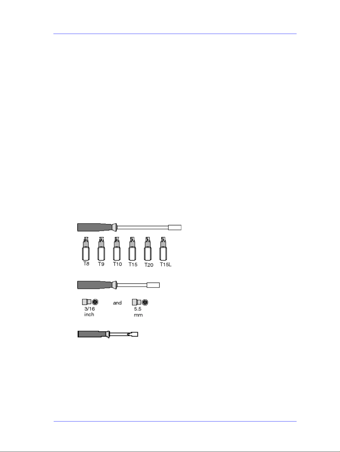
Required Tools
The following tools are required to disassemble and repair the Printer.
Long Torx Screwdriver with
the indicated attachments
Nut driver with the
indicated attachments
Small flat-blade screwdriver
HP DesignJets 500 and 800 Series Printers Service Manual
8-3
Page 4

Removal and Installation
Screw Types
T ype Torx Length
(mm)
Head Type Thread Type Part Number
A T-20 17 Pan Taptite 0515-1743
B T-10 8.0 Pan Taptite 0515-2200
C T-20 10 Pan Taptite 0515-2282
D T-10 17.5 Pan Washer Plastite 0515-2675
E T-15 12.7 Pan Plastite 0624-0769
F T-15 20 Pan Plastite 0624-0771
G T-8 12.7 Pan Plastite 0624-0768
H T-20 35 Pan Taptite 0515-2521
I T-15 9.5 Pan Plastite 0515-2981
J T-10 8 Pan Machined 0515-2246
8-4
HP DesignJets 500 and 800 Series Printers Service Manual
Page 5
Removal and Installation
Left Hand Cover
Removal
WARNING Switch off the printer and remove the power cable.
NOTE Refer to the table on Page 8-4 for information on screw types.
1. Remove the Spindle.
2. Remove 3 T-20 screws (Type F) from
the Rear of the Left Hand Cover.
3. Remove the LAN Card Cover from
the back of the Left Hand Cover.
HP DesignJets 500 and 800 Series Printers Service Manual
8-5
Page 6
Removal and Installation
4. Remove 1 T-20 screw (Type F) from
the front of Left Hand Cover.
5. Open the Window and remove 1 T-20
screw (Type F) from the side-plate.
NOTE Be careful not to drop the
screw into the Printer.
6. Remove the Left Hand Cover.
8-6
HP DesignJets 500 and 800 Series Printers Service Manual
Page 7
Removal and Installation
Right Hand Cover
Removal
WARNING Switch off the printer and remove the power cable.
NOTE Refer to the table on Page 8-4 for information on screw types.
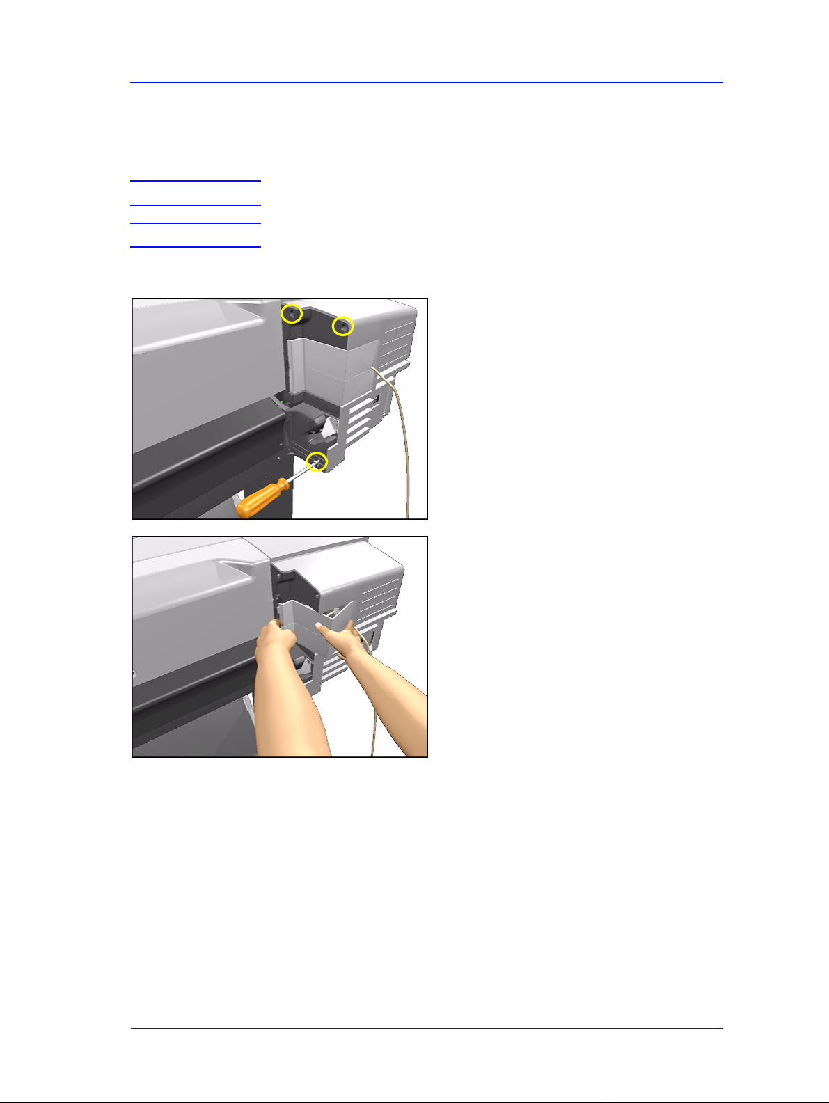
1. Remove 1 T-20 screw (Type F) from
the back of the Right Hand Cover.
2. Open the Ink Cartridge Door and
remove 1 T-20 screw (Type F) from
the back of the Right Hand Cover.
3. Keep the Ink Cartridge Door open and
remove 1 T-20 screw (Type F) from
the top of the Right Hand Cover.
HP DesignJets 500 and 800 Series Printers Service Manual
8-7
Page 8
Removal and Installation
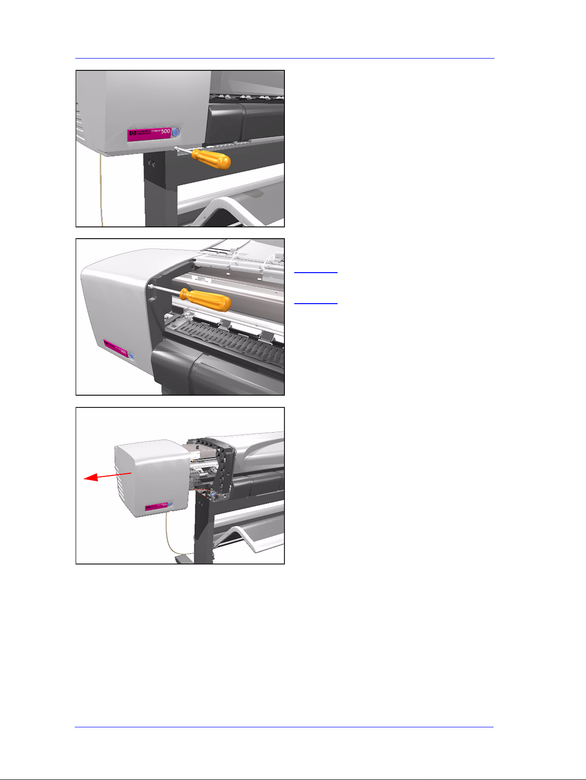
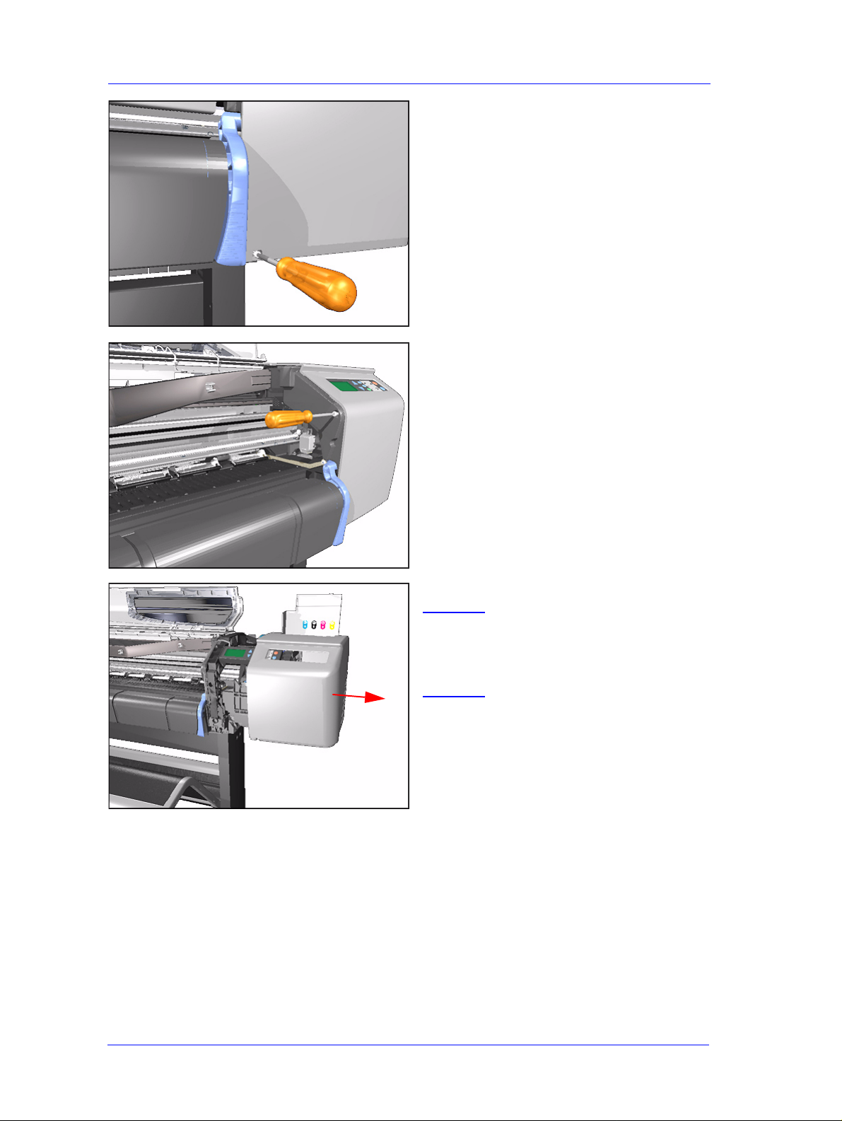
4. Remove 1 T-20 screw (Type F) from
the front of the Right Hand Cover.
5. Open the Window and remove 1 T-20
screw (Type F) from the side plate.
6. Remove the Right Hand Cover.
NOTE Always keep the Ink
Cartridge door open when
removing/installing the Right
Hand Cover.
8-8
HP DesignJets 500 and 800 Series Printers Service Manual
Page 9
Removal and Installation
Front Panel
Removal
WARNING Switch off the printer and remove the power cable.
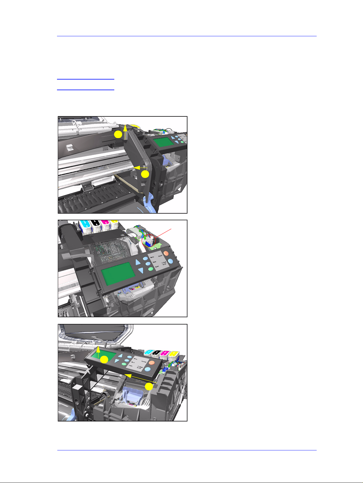
1. Remove the the Right Hand Cover -
Refer to Page 8-7.
2. Remove the Right Hand Trim.
2
1
Disconnect
3. Disconnect Front Panel Connector
from the ISS PCA.
4. Unclip the Front Panel and remove
from the Printer.
1
2
HP DesignJets 500 and 800 Series Printers Service Manual
8-9
Page 10
Removal and Installation
Window and Top Cover
Removal
WARNING Switch off the printer and remove the power cord.
NOTE Refer to the table on Page 8-4 for information on screw types.
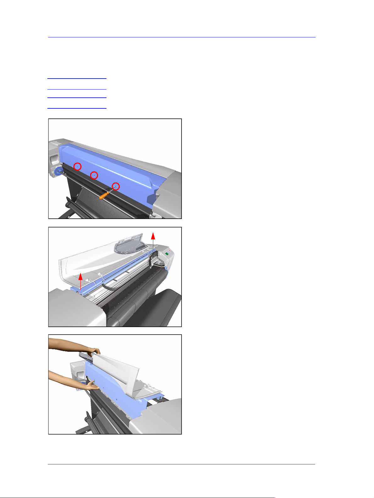
1. Remove the following screws
(Type A) from the rear that attach the
Top Cover to the Printer:
n 2 T-20 screws for the 24" model.
n 3 T-20 screws for the 42" model.
2. Raise Window and unclip at both
ends.
3. Lift up complete assembly (Window
and Top Cover) and remove from
Printer.
8-10
HP DesignJets 500 and 800 Series Printers Service Manual
Page 11
Removal and Installation
Media Deflectors
Removal
WARNING Switch off the printer and remove the power cord.
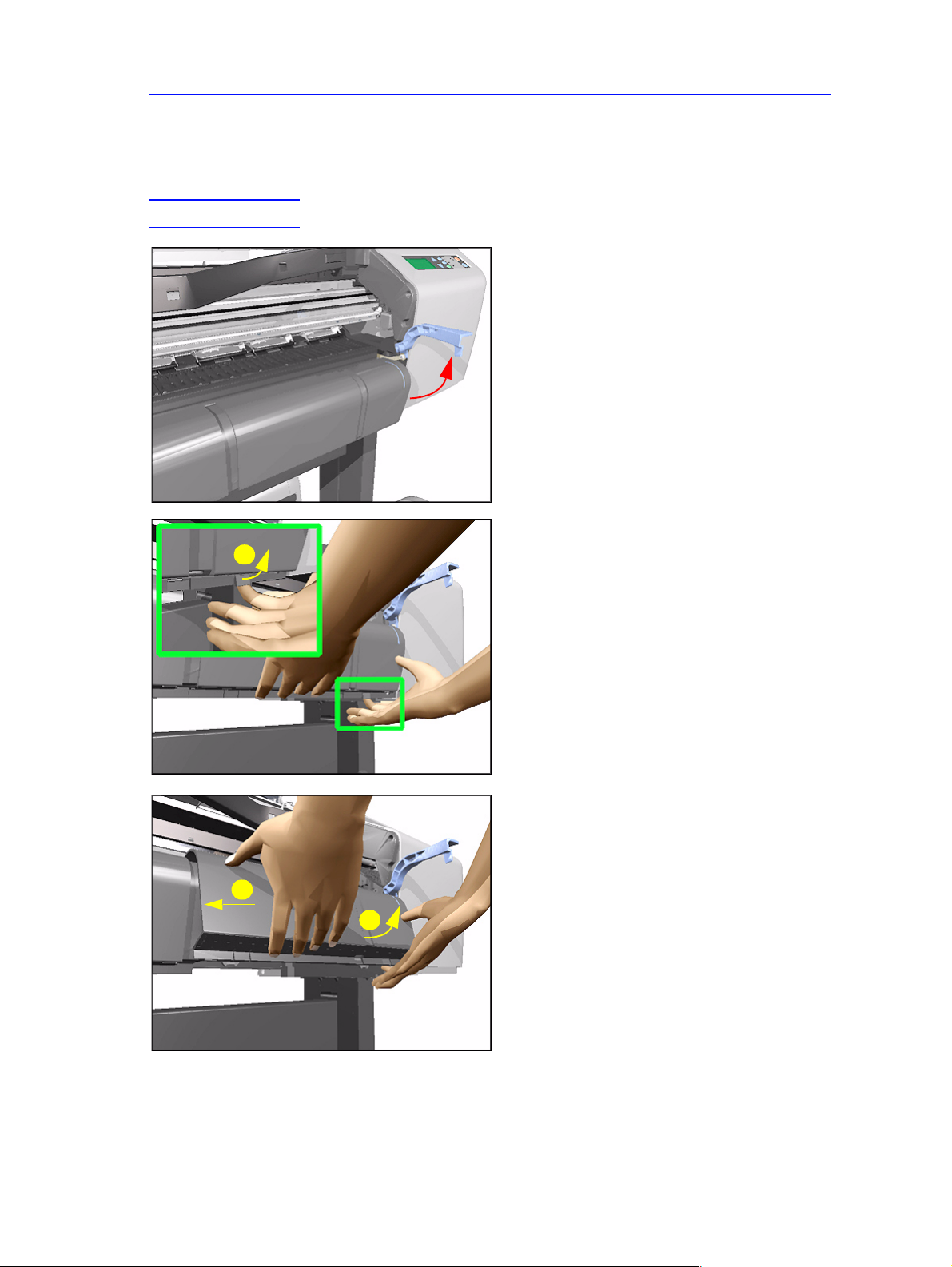
1. Make sure the Media Lever is in the
UP Position.
2. Lift tab up and slide Right Deflector
1
to the left and lift up.
2
3
HP DesignJets 500 and 800 Series Printers Service Manual
8-11
Page 12
Removal and Installation
3. Lift tab up and slide Middle Deflector
to the right and lift up.
2
3
1
4. Lift tab up and slide Left Deflector to
the right and lift up.
2
3
1
8-12
HP DesignJets 500 and 800 Series Printers Service Manual
Page 13
Removal and Installation
Left End Roll-Feed
Removal
WARNING Switch off the printer and remove the power cord.
NOTE Refer to the table on Page 8-4 for information on screw types.
1. Remove the Left Hand Cover - Refer
to Page 8-5
2. Remove the Spindle.
3. Remove 1 T-20 screw (Type F) from
the Left Hand Roll-Feed (located on
the inside next to the Electronics
Module).
4. Remove 2 T-20 screws (Type F) from
the Left End Roll-Feed.
HP DesignJets 500 and 800 Series Printers Service Manual
8-13
Page 14
Removal and Installation
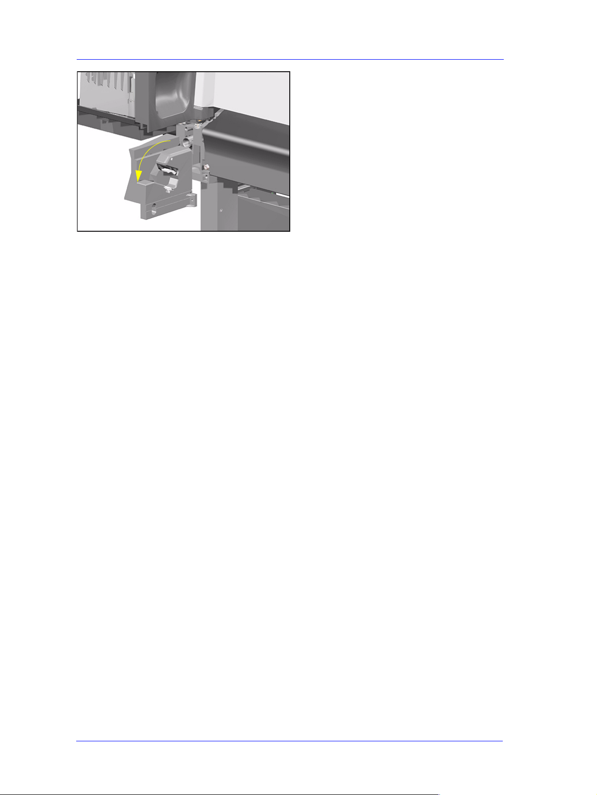
5. Move Left End Roll-Feed down and
remove from Printer.
8-14
HP DesignJets 500 and 800 Series Printers Service Manual
Page 15
Removal and Installation
Right End Roll-Feed
Removal
WARNING Switch off the printer and remove the power cord.
NOTE Refer to the table on Page 8-4 for information on screw types.
1. Remove the Right Hand Cover - Refer
to Page 8-7.
2. Remove the Spindle.
3. Remove 1 T-20 screw (Type F) from
the Right Hand Roll-Feed.
4. Remove 2 T-20 screws (Type F) from
the Right Hand Roll-Feed (located on
the inside).
HP DesignJets 500 and 800 Series Printers Service Manual
8-15
Page 16
Removal and Installation
5. Remove Right Hand Roll-Feed.
8-16
HP DesignJets 500 and 800 Series Printers Service Manual
Page 17
Removal and Installation
Back Platen
Removal
WARNING Switch off the printer and remove the power cord.
NOTE Refer to the table on Page 8-4 for information on screw types.
1. Remove the Spindle.
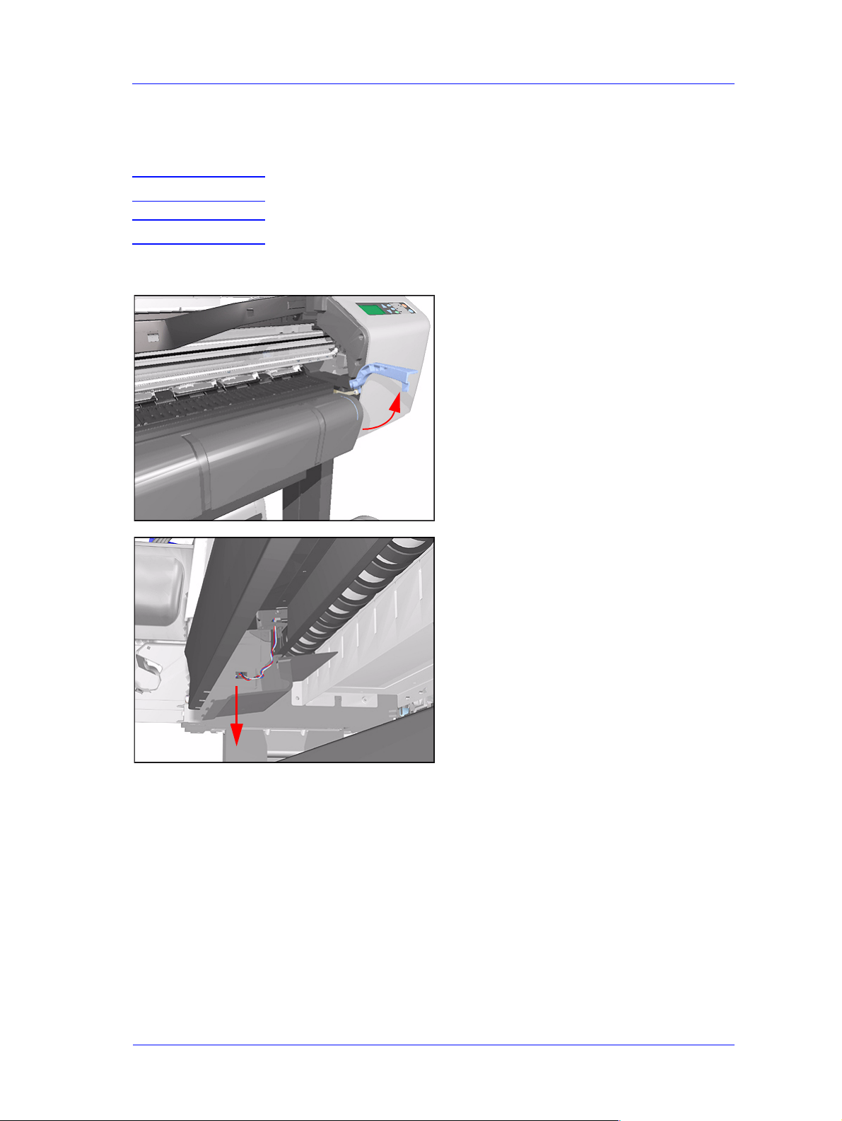
2. Make sure the Media Lever is in the
UP Position.
3. Unclip the Media Sensor Cover and
remove from the Printer.
HP DesignJets 500 and 800 Series Printers Service Manual
8-17
Page 18
Removal and Installation
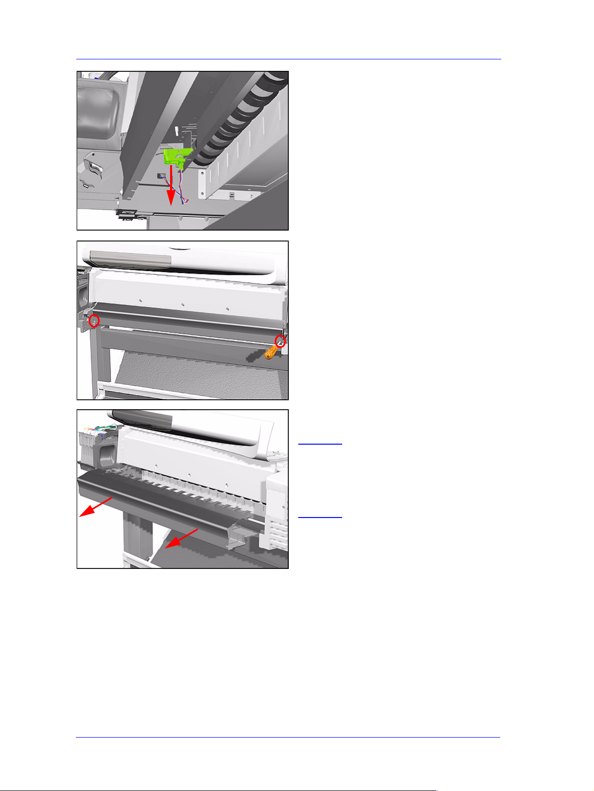
4. Unclip the Media Sensor from
underneath the Back Platen.
5. Remove 2 T -15 screws (Type E) from
the Back Platen.
6. Remove the Back Platen by pulling it
evenly towards you.
NOTE Make sure that the Media
Sensor is not atta ched to the
Back Platen to prevent
pulling the cable and
breaking the sensor.
8-18
HP DesignJets 500 and 800 Series Printers Service Manual
Page 19
Removal and Installation
Media Sensor
Removal
WARNING Switch off the printer and remove the power cord.
1. Remove the Right Hand Cover - Refer
to Page 8-7.
2. Remove the Spindle.
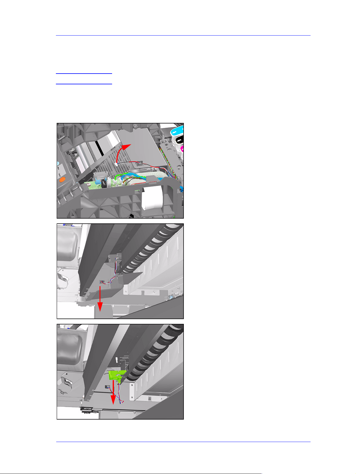
3. Disconnect the Media Sensor Cable
from the ISS PCA.
4. Unclip the Media Sensor Cover and
remove from the Printer.
5. Unclip the Media Sensor from
underneath the Back Platen. Route the
Media Sensor cable out where
necessary and remove the Media
Sensor.
HP DesignJets 500 and 800 Series Printers Service Manual
8-19
Page 20
Removal and Installation
Formatter
Removal
WARNING Switch off the printer and remove the power cord.
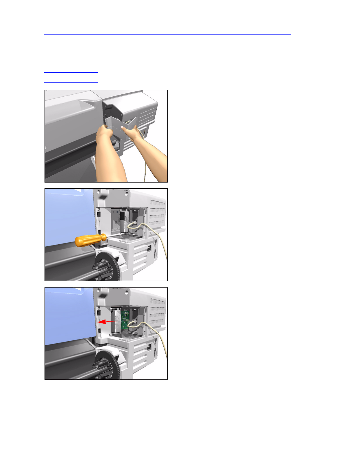
1. Remove the LAN Card Cover from
the back of the Left Hand Cover.
2. With a flat end screwdriver, unscrew
the 2 screws that attach the Formatter
to the Electronics.
8-20
3. Remove the Formatter.
HP DesignJets 500 and 800 Series Printers Service Manual
Page 21
Removal and Installation
LAN Card
Removal
WARNING Switch off the printer and remove the power cord.
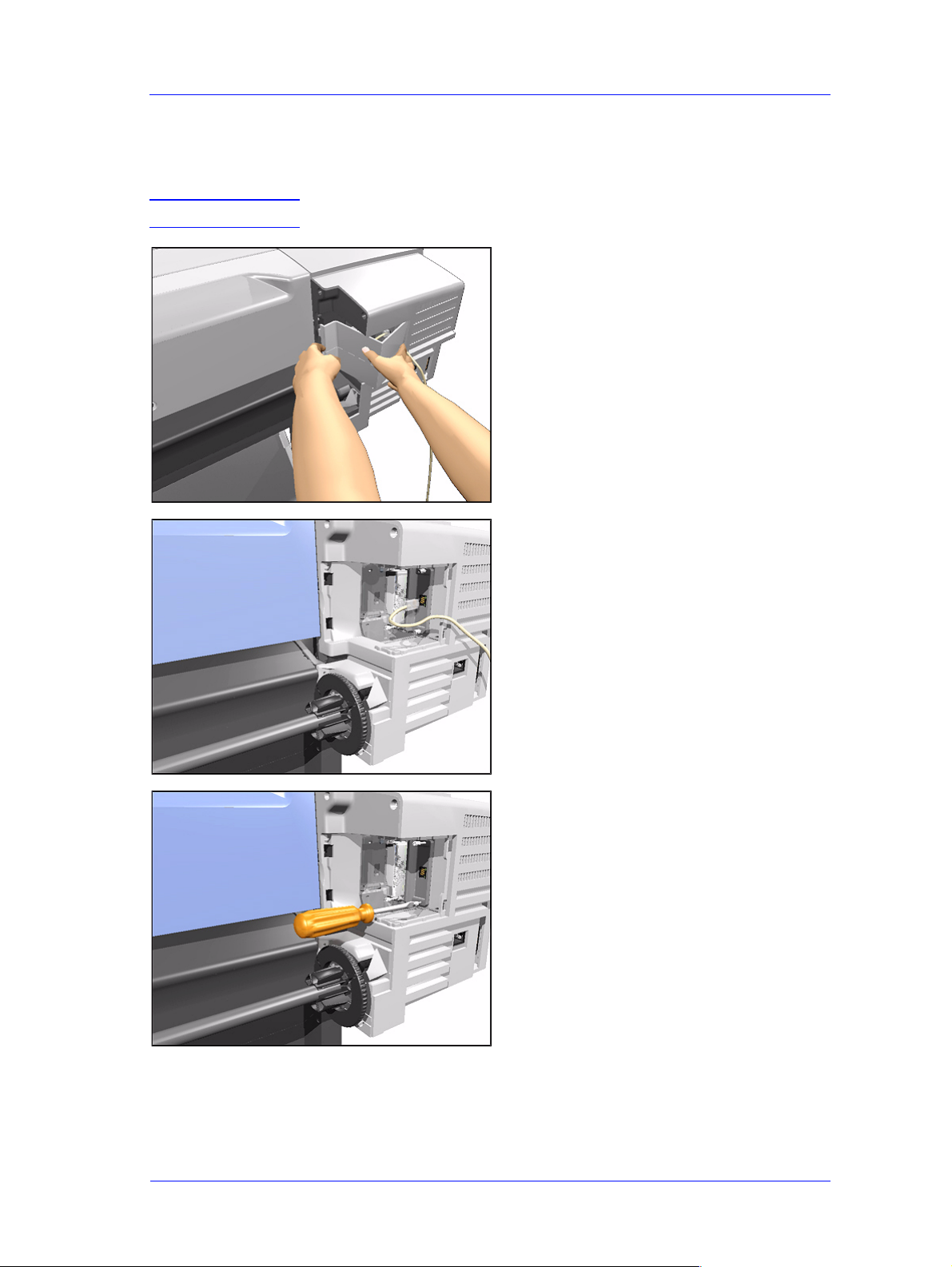
1. Remove the LAN Card Cover from
the back of the Left Hand Cover.
2. Disconnect the LAN Cable from the
LAN Card
3. With a flat end screwdriver, unscrew
HP DesignJets 500 and 800 Series Printers Service Manual
the 2 screws that attach the LAN Card
to the Electronics.
8-21
Page 22
Removal and Installation
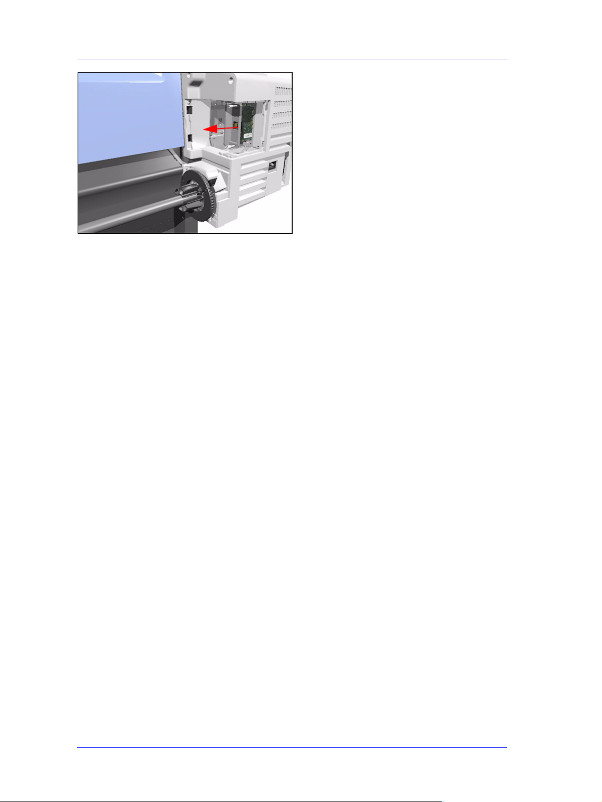
4. Remove the LAN Card from the
Printer.
8-22
HP DesignJets 500 and 800 Series Printers Service Manual
Page 23
Removal and Installation
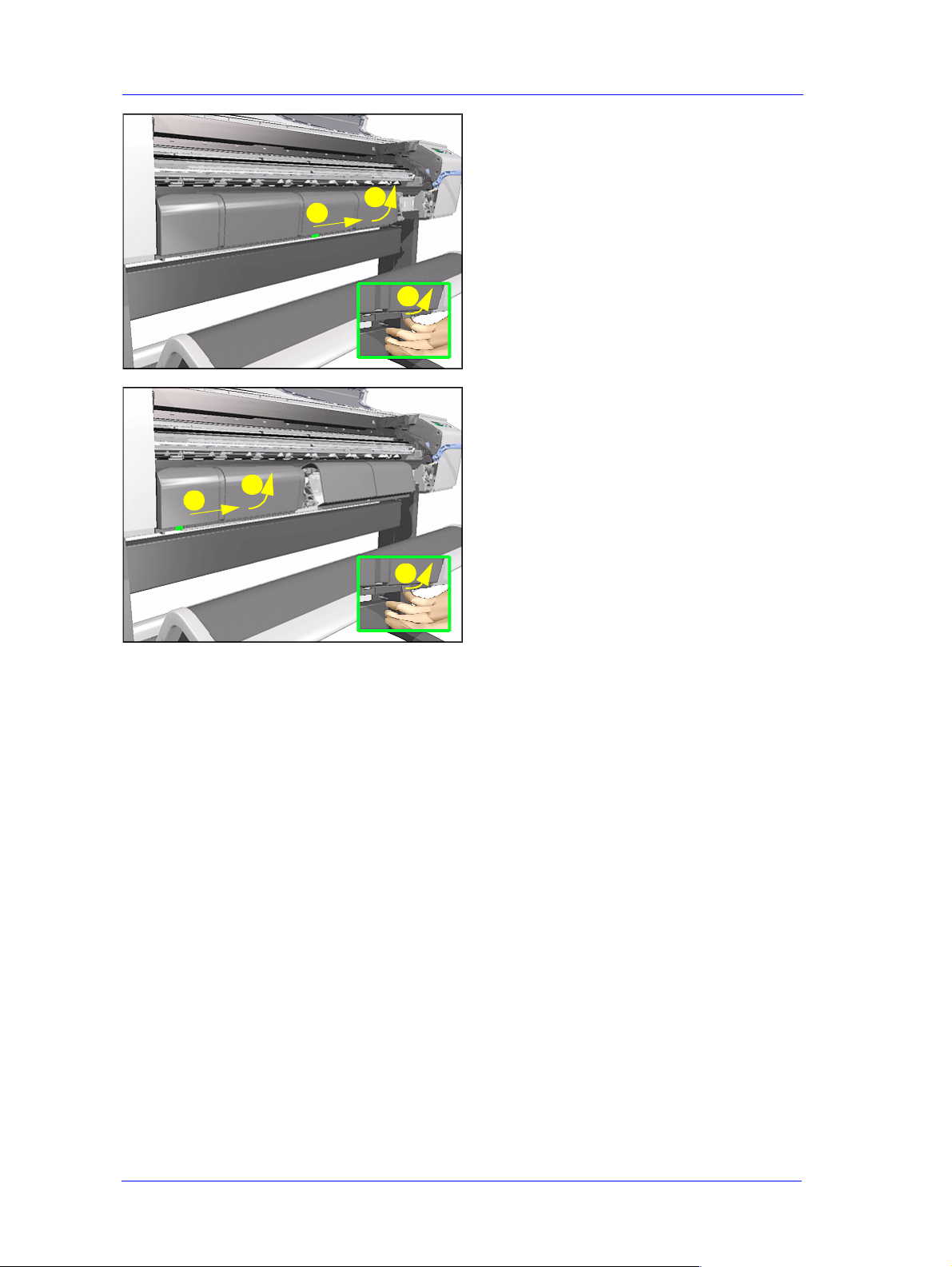
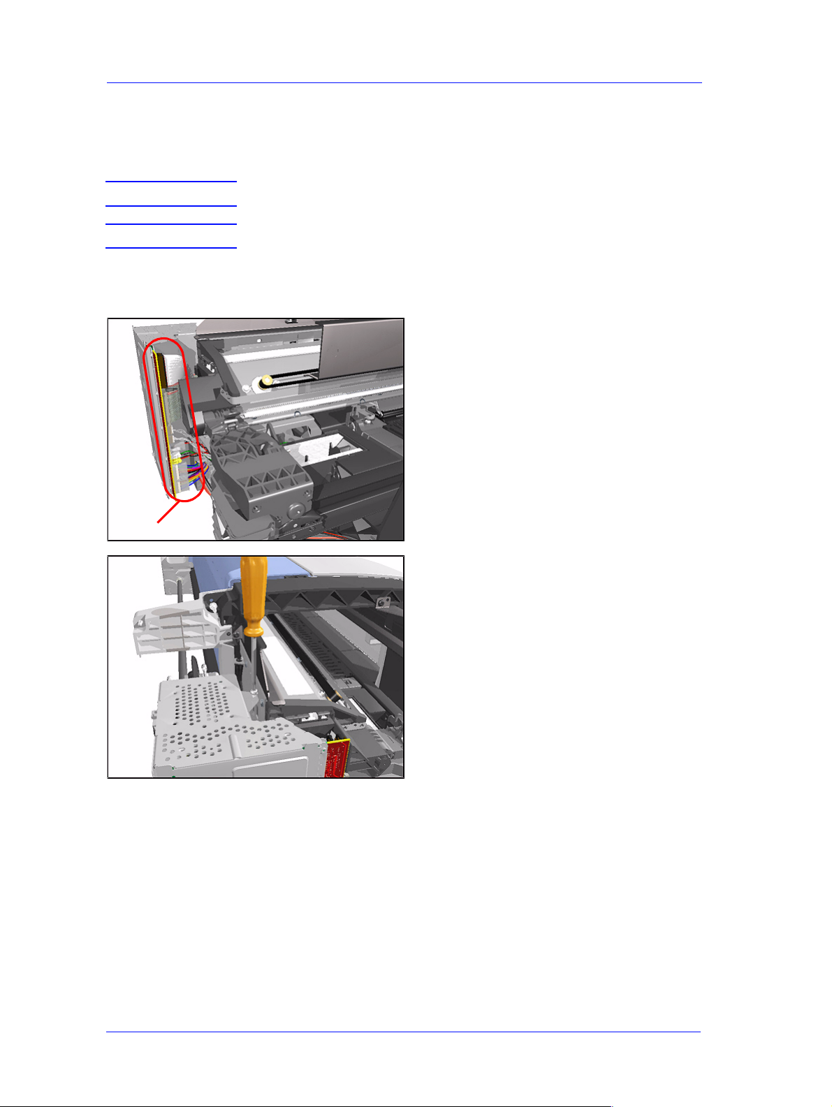
Spittoon
Removal
WARNING Switch off the printer and remove the power cord.
1. Remove the Left Hand Cover - Refer
to Page 8-5.
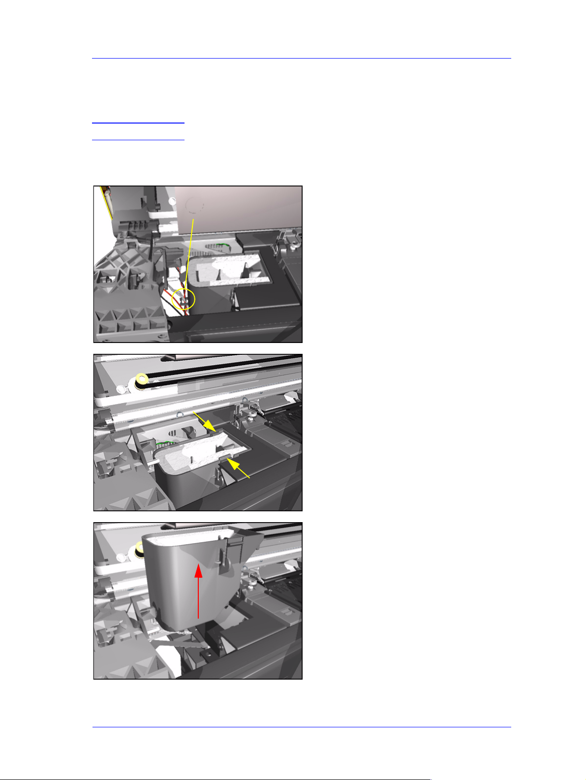
2. Release the cables that are attached to
Release
the Spittoon.
3. Press in the 2 clips to release the
Spittoon.
4. Lift up the Spittoon and remove from
the Printer.
HP DesignJets 500 and 800 Series Printers Service Manual
8-23
Page 24
Removal and Installation
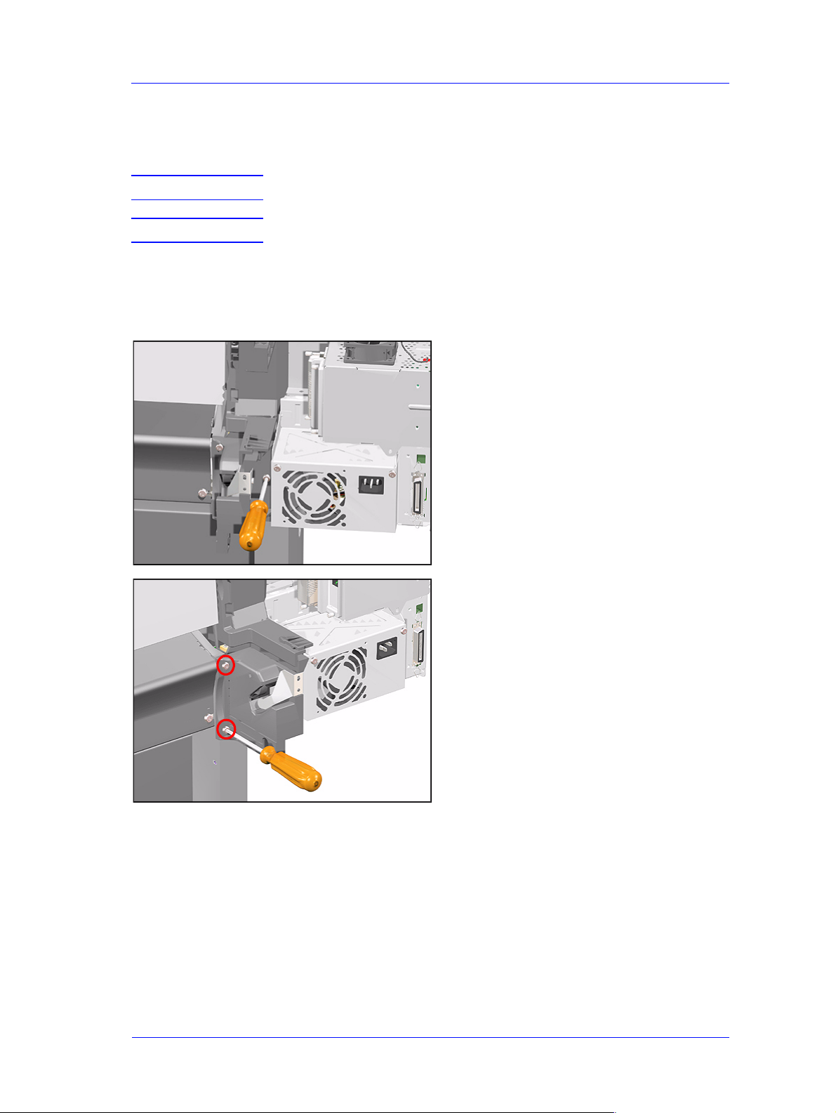
Electronics Module
Removal
WARNING Switch off the printer and remove the power cord.
NOTE Refer to the table on Page 8-4 for information on screw types.
1. Remove the Left Hand Cover - Refer
to Page 8-5.
2. Disconnect ALL the cables from the
Electronics Module.
Disconnect
3. Remove 1 T-10 screw (Type B) from
the top of the Electronics Module.
8-24
HP DesignJets 500 and 800 Series Printers Service Manual
Page 25
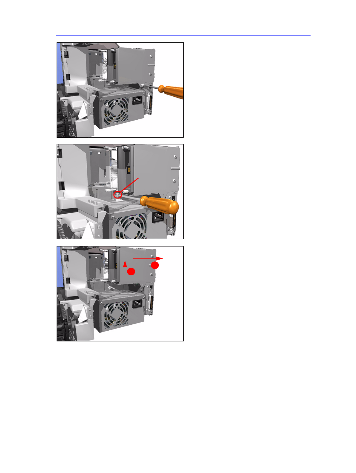
Loosen Only
Removal and Installation
4. Remove 1 T-10 screw (Type B) from
the back of the Electronics Module.
5. Loosen 1 T-10 screw (Type B) just
below the Electronics Module.
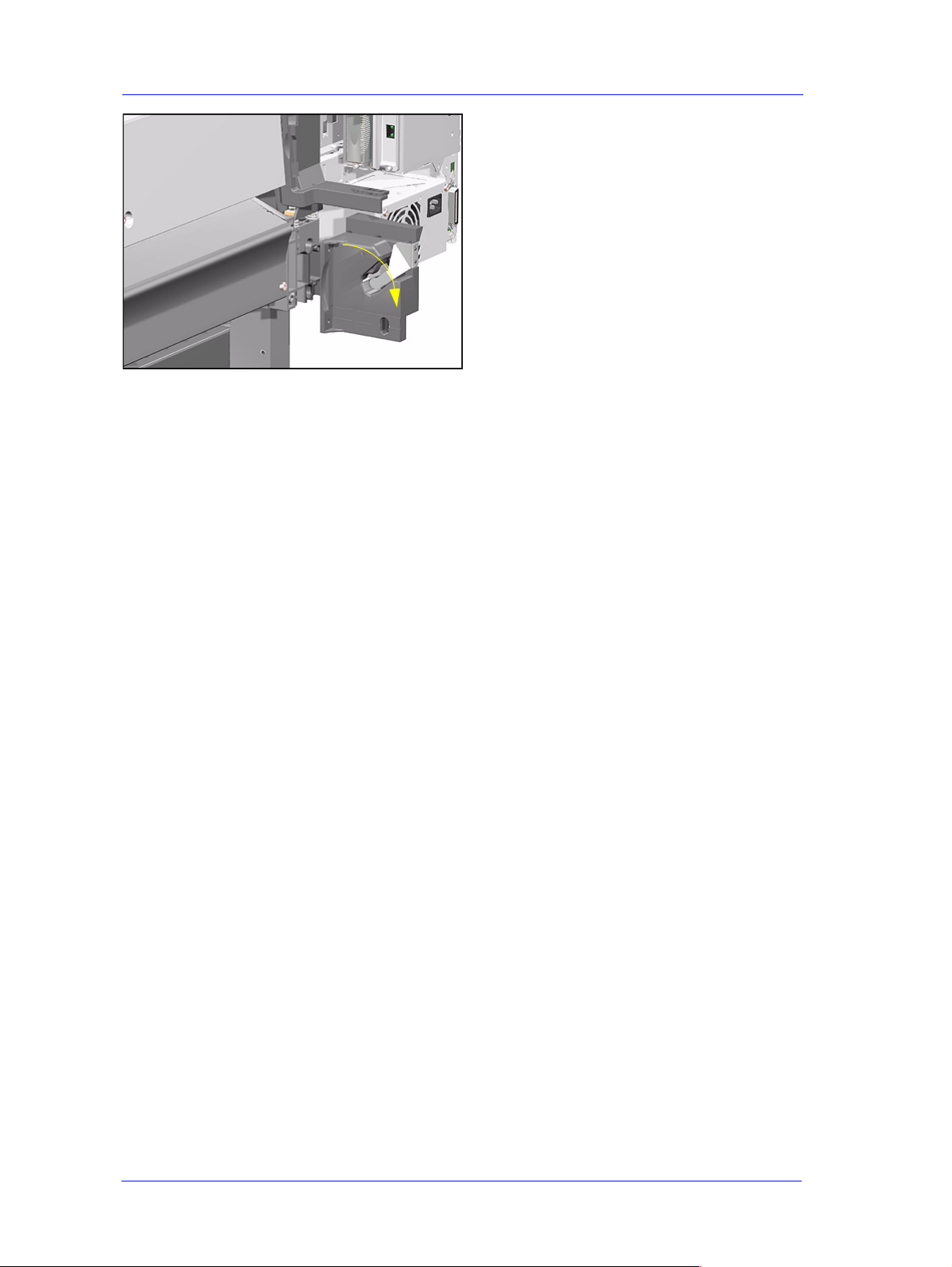
6. Lift the Electronics Module up and
towards the right and remove from
2
1
Printer.
HP DesignJets 500 and 800 Series Printers Service Manual
8-25
Page 26
Removal and Installation
Installing the Electronics Module
NOTE When installing the
Electronics Module, make
sure that you insert the tab
on the Printer into the slot in
the Electronics Module.
8-26
HP DesignJets 500 and 800 Series Printers Service Manual
Page 27
Removal and Installation
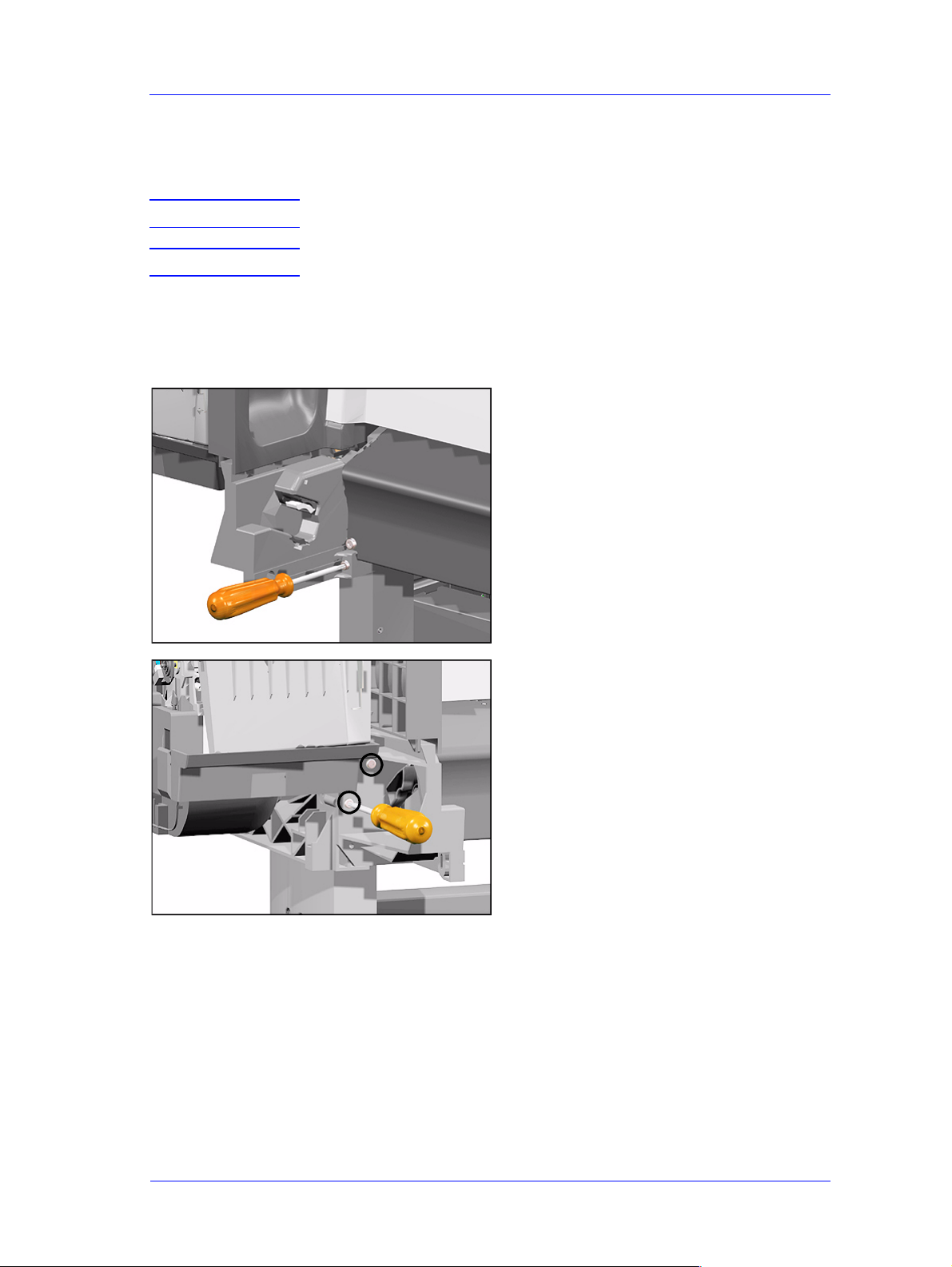
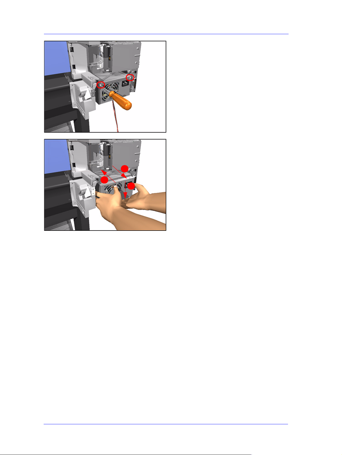
Power Supply
Removal
WARNING Switch off the printer and remove the power cord.
NOTE Refer to the table on Page 8-4 for information on screw types.
1. Remove the Left Hand Cover - Refer
to Page 8-5.
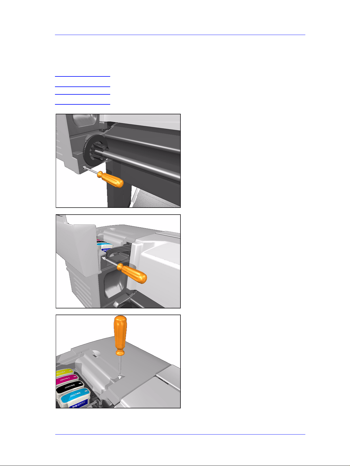
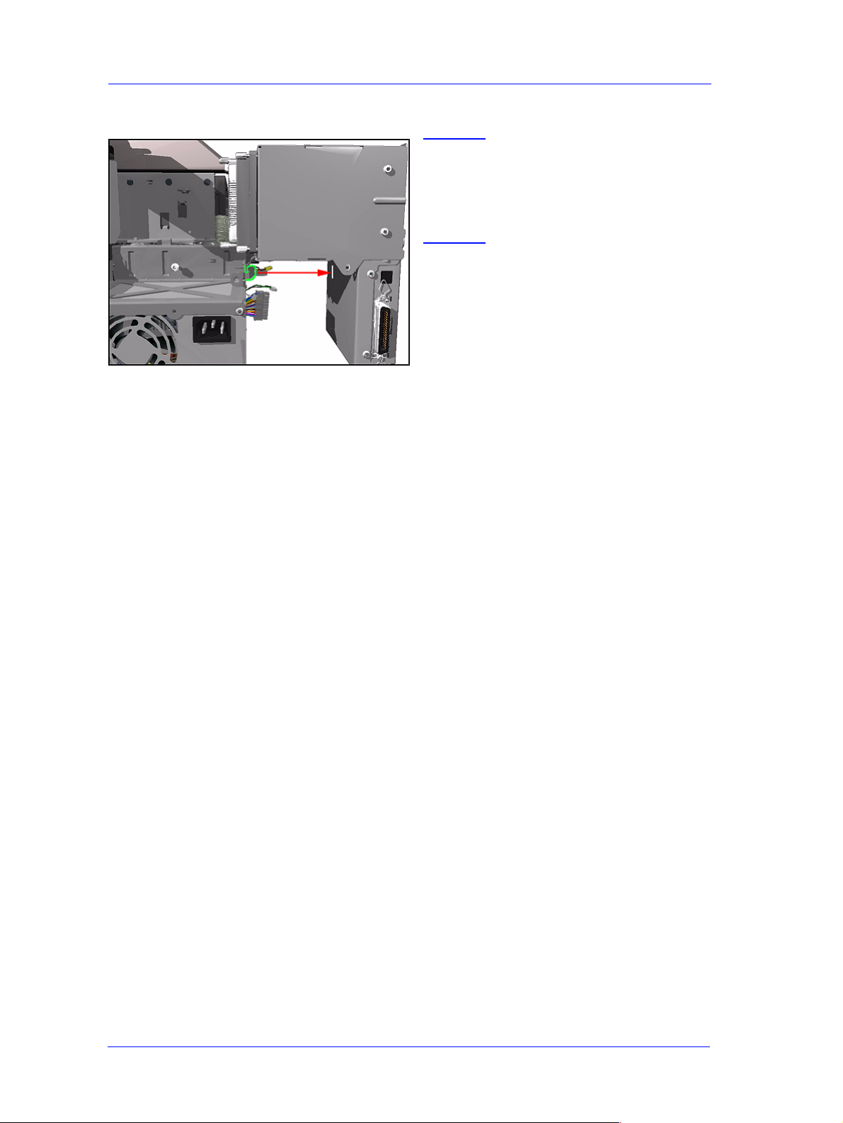
2. Remove 1 T-10 (Type B) screw from
the Power Switch on the front of the
Printer.
Disconnect
3. Disconnect the Power Supply Cable
from the Electronics Module.
HP DesignJets 500 and 800 Series Printers Service Manual
8-27
Page 28
Removal and Installation
1
4. Remove 2 T-10 screws (Type B) that
secure Power Supply to the Bracket.
5. Remove the Power Supply as one
assembly (Power Switch and Power
Supply Unit).
3
2
8-28
HP DesignJets 500 and 800 Series Printers Service Manual
Page 29
Removal and Installation
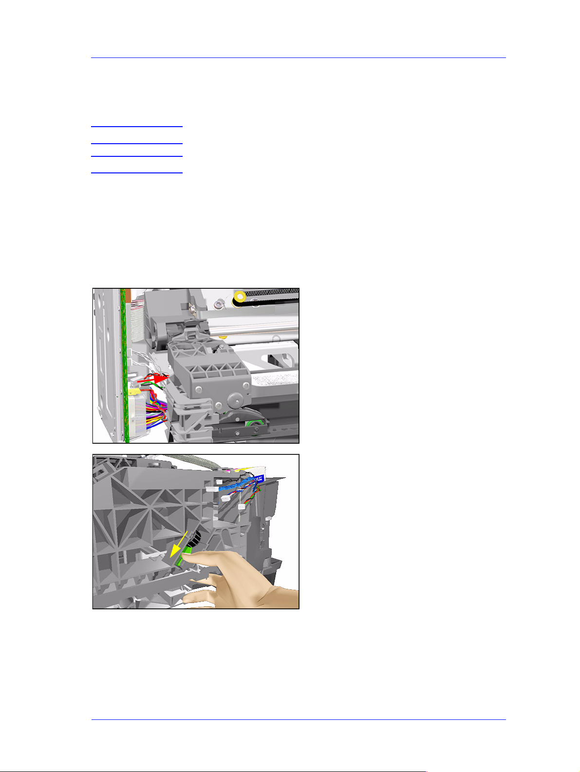
Scan-Axis Motor Assembly
Removal
WARNING Switch off the printer and remove the power cord.
NOTE Refer to the table on Page 8-4 for information on screw types.
1. Remove the Left Hand Cover - Refer
to Page 8-5.
2. Remove the Right Hand Cover - Refer
to Page 8-7.
3. Remove the Power Supply - Refer to
Page 8-27.
4. Disconnect the Scan-Axis Motor
Cable from the Electronics Module.
5. Release the tension from the right
HP DesignJets 500 and 800 Series Printers Service Manual
hand side of the Belt by pulling the
Tensioner down and pushing it
towards you to lock it into position.
8-29
Page 30

Removal and Installation
6. Remove the left hand side of the Belt
from the Scan-Axis Motor.
7. Remove 2 T-20 screws (Type C) from
the Scan-Axis Motor.
NOTE Make sure that you keep hold
of the Scan-Axis Motor when
removing the screws,
otherwise the Motor could
fall and be damaged.
8. Remove the Scan-Axis Motor.
8-30
HP DesignJets 500 and 800 Series Printers Service Manual
Page 31

Installing the Scan-Axis Motor
Removal and Installation
NOTE When installing the Scan-
Axis Motor, make sure that
you insert the notch in the
Printer into the slot in the
Scan-Axis Motor.
HP DesignJets 500 and 800 Series Printers Service Manual
8-31
Page 32

Removal and Installation
Cutter Assembly
Removal
WARNING Switch off the printer and remove the power cord.
1. Select the "Change Cutter" option
from the Front Panel Menu.
2. Open the Window.
3. Lift Tab UP and pull out the Cutter
Assembly.
1
3
2
8-32
HP DesignJets 500 and 800 Series Printers Service Manual
Page 33

Removal and Installation
Left Encoder Holder
Removal
WARNING Switch off the printer and remove the power cord.
NOTE Refer to the table on Page 8-4 for information on screw types.
1. Remove the Left Hand Cover - Refer
to Page 8-5.
2. Remove 1 T-15 screw (Type E) from
the Left Encoder Holder (attaches the
Encoder Strip to the Holder).
3. Release the Encoder Strip from the
left hand side.
NOTE The Encoder S trip is sharp so
be careful when touching it.
HP DesignJets 500 and 800 Series Printers Service Manual
8-33
Page 34

Removal and Installation
4. Disconnect the Trailing Cable and
unclip the Ferrite and remove.
5. Remove the Electronics Module Refer to Page 8-24.
6. Remove 2 T-20 screws (Type A) from
the Left Encoder Holder.
7. Remove the Left Encoder Holder,
making sure that you first unclip both
the Trailing Cable and the
Interconnect Cable.
8-34
HP DesignJets 500 and 800 Series Printers Service Manual
Page 35

Removal and Installation
Cutter Bushing
Removal
WARNING Switch off the printer and remove the power cord.
1. Remove the Left Hand Cover - Refer
to Page 8-5.
2. Remove the Electronics Module -
Refer to Page 8-24.
3. Remove the Cutter Assembly - Refer
to Page 8-32.
4. Remove the Left Encoder Holder -
Refer to Page 8-33.
5. Slide the Cutter Bushing to the Left
and remove from the Printer.
HP DesignJets 500 and 800 Series Printers Service Manual
8-35
Page 36

Removal and Installation
Cutter Guide Bracket
Removal
WARNING Switch off the printer and remove the power cord.
NOTE Refer to the table on Page 8-4 for information on screw types.
1. Remove the Left Hand Cover - Refer
to Page 8-5.
2. Remove the Cutter from its position.
3. Remove the Vacuum Fan Cable from
the Cutter Guide Bracket.
8-36
HP DesignJets 500 and 800 Series Printers Service Manual
Page 37

Removal and Installation
4. Remove 1 T-10 screw (Type B) from
the Cutter Guide Bracket.
5. Slide the Cutter Guide Bracket out of
the Printer.
HP DesignJets 500 and 800 Series Printers Service Manual
8-37
Page 38

Removal and Installation
Drive Roller Encoder Sensor
Removal
WARNING Switch off the printer and remove the power cord.
NOTE Refer to the table on Page 8-4 for information on screw types.
1. Remove the Left Hand Cover - Refer
to Page 8-5.
2. Remove the Spittoon - Refer to Page
8-23.
3. Remove the Cutter Guide Bracket Refer to Page 8-36.
4. Disconnect the Encoder Sensor Cable
from the Electronics Module.
8-38
5. Remove 1 T-8 screw (Type G) from
the Encoder Sensor Cover.
HP DesignJets 500 and 800 Series Printers Service Manual
Page 39

Removal and Installation
6. Depress the clip and remove the
Encoder Sensor Cover.
2
1
7. Remove 1 T-8 screw (Type G) from
the Encoder Sensor.
8. Move the Encoder Sensor to the left
and remove (including the Encoder
Sensor Cable).
3
2
1
HP DesignJets 500 and 800 Series Printers Service Manual
8-39
Page 40

Removal and Installation
Trailing Cable
Removal
NOTE Refer to the table on Page 8-4 for information on screw types.
1. Perform the Service Utility "Unlock
Carriage" - Refer to Page 4-22.
NOTE Switch off the Printer after
performing this Utility.
2. Remove the Left Hand Cover - Refer
to Page 8-5.
3. Remove the Top Cover and Window Refer to Page 8-10.
4. Manually move the carriage to the
correct position to remove the Tubes
Assembly from the Carriage.
8-40
5. Release the latch and lift up the
Carriage Cover.
HP DesignJets 500 and 800 Series Printers Service Manual
Page 41

Removal and Installation
6. Remove all the Printheads.
7. Loosen 1 T-8 screw that secures the
Tubes to the Carriage.
Unclip
8. Unclip the Tubes from the Carriage
and lift up.
HP DesignJets 500 and 800 Series Printers Service Manual
8-41
Page 42

Removal and Installation
9. Move the Tubes Assembly clear from
the Carriage Assembly.
10. Close the Carriage Cover.
11.
Unclip the Carriage Cover (clip located
on the left hand side of the Carriage use a screwdriver if necessary).
8-42
HP DesignJets 500 and 800 Series Printers Service Manual
Page 43

Removal and Installation
Remove
12. Remove the clip securing the Trailing
Cable.
13. Disconnect the Trailing Cable from
the Carriage Assembly.
14. Slide the T railin g Cable out of the cl ip
inside the Carriage Assembly and then
2
1
lift up to free it from the Carriage.
HP DesignJets 500 and 800 Series Printers Service Manual
8-43
Page 44

Removal and Installation
15. Move the Carriage Assembly to the
right so that the Trailing Cable clips
on the beam are visible.
16. Release ALL the clips on the beam
that secure the Trailing Cable.
17. Slide the Plastic Holder, that kept the
Trailing Cable flat, to the right to
release it from the retaining clip.
8-44
HP DesignJets 500 and 800 Series Printers Service Manual
Page 45

Removal and Installation
18. Remove the Plastic Holder from the
Printer.
19. Release the Trailing Cable clips.
20. Disconnect the Trailing Cable from
the Electronics Module.
HP DesignJets 500 and 800 Series Printers Service Manual
8-45
Page 46

Removal and Installation
21. Unclip the Ferrite and remove.
22. Slide the Trailing Cable through the
Carriage Assembly and remove.
8-46
HP DesignJets 500 and 800 Series Printers Service Manual
Page 47

Installing the Trailing Cable
Align
Removal and Installation
NOTE When installing the Trailing
Cable, make sure that you
align the red lines on the
Trailing Cable as shown in
these drawings.
Align
HP DesignJets 500 and 800 Series Printers Service Manual
8-47
Page 48

Removal and Installation
Ink Supply Station
Removal
WARNING Switch off the printer and remove the power cord.
NOTE Refer to the table on Page 8-4 for information on screw types.
1. Remove the Ink Cartridges.
2. Remove the Right Hand Cover - Refer
to Page 8-7.
3. Disconnect the Ink Supply Station
Cables (Connectors P2 and P4) from
the Interconnect PCA.
Lift up Bracket
4. Release the Tubes Bracket from the
Ink Supply Station by pushing the
clips inwards and lifting up the
Bracket.
8-48
HP DesignJets 500 and 800 Series Printers Service Manual
Page 49

Removal and Installation
5. Remove 1 T-15 screw (Type E) from
the top of the Assembly.
6. Remove the Ink Supply Station from
the Printer.
3
NOTE The ISS is a complete
Assembly that includes the
Cartridge Holder (top) and
1
2
Tray (bottom). The complete
Assembly must be removed/
installed together.
HP DesignJets 500 and 800 Series Printers Service Manual
8-49
Page 50

Removal and Installation
Interconnect PCA
Removal
WARNING Switch off the printer and remove the power cord.
NOTE Refer to the table on Page 8-4 for information on screw types.
1. Remove the Right Hand Cover - Refer
to Page 8-7.
2. Disconnect all the cables connected to
the Interconnect PCA.
3. Remove 1 T-15 screw (Type E) from
the Interconnect PCA.
8-50
HP DesignJets 500 and 800 Series Printers Service Manual
Page 51

Removal and Installation
4. Lift the Interconnect PCA and
remove.
HP DesignJets 500 and 800 Series Printers Service Manual
8-51
Page 52

Removal and Installation
Service St at ion and Aerosol Fan
Removal
NOTE Refer to the table on Page 8-4 for information on screw types.
1. Perform the Service Utility "Unlock
Carriage" - Refer to Page 4-22.
NOTE Switch off the Printer after
performing this Utility.
2. Remove the Right Hand Cover - Refer
to Page 8-7.
3. Manually move the Carriage out of
the Service Station.
4. Disconnect the Service Station and
Aerosol Fan Cables (connectors P5
and P9) from the Interconnect PCA.
8-52
HP DesignJets 500 and 800 Series Printers Service Manual
Page 53

Removal and Installation
5. Remove 2 T -15 screws (Type E) from
inside the Service Station.
6. Make sure you lift the Carriage Lock
before sliding out the Service Station
out of the Printer.
7. Slide the Assembly towards you (to
the right) and remove.
HP DesignJets 500 and 800 Series Printers Service Manual
8-53
Page 54

Removal and Installation
Installing the Service Station/Aerosol Fan
NOTE When installing the Service
Station, make sure that you
line up the tabs on the
Service Station with the
structure of the Service
Station Holder.
8-54
HP DesignJets 500 and 800 Series Printers Service Manual
Page 55

Removal and Installation
Cutter Guide
Removal
WARNING Switch off the printer and remove the power cord.
1. Remove the Cutter Assembly - Refer
to Page 8-32.
2. Place your hands on the Cutter Guide
(as shown in the drawing) and lift up.
This is a cross-sectional view of the
Printer showing how the Cutter Guide is
seated.
3. Pull the Cutter Guide out to the right
and remove from the Printer.
HP DesignJets 500 and 800 Series Printers Service Manual
8-55
Page 56

Removal and Installation
Print Platen
Removal
WARNING Switch off the printer and remove the power cord.
NOTE Refer to the table on Page 8-4 for information on screw types.
1. Remove the Cutter Assembly - Refer
to Page 8-32.
2. Remove the Cutter Guide - Refer to
Page 8-55.
3. Remove the following screws
(Type G) from the Print Platen:
n 24 Screws (T-8) for the 24" model.
n 36 Screws (T-8) for the 42" model.
4. Pull the tabs out slightly and lift each
piece of the Print Platen from the
Printer.
NOTE
The Print Platen is split into 2
pieces on the 24" model and
into 3 pieces on the 42" model.
8-56
HP DesignJets 500 and 800 Series Printers Service Manual
Page 57

Removal and Installation
Service St at ion Holder
Removal
WARNING Switch off the printer and remove the power cord.
NOTE Refer to the table on Page 8-4 for information on screw types.
1. Remove the Left Hand Cover - Refer
to Page 8-5.
2. Remove the Right Hand Cover - Refer
to Page 8-7.
3. Remove the Right Hand Trim.
4. Remove the Front Panel Assembly -
Refer to Page 8-9.
5. Remove the Interconnect PCA - Refer
to Page 8-50.
6. Remove the Service Station - Refer to
Page 8-52.
7. Remove the Fork Idler, Tensioner and
Idler Pulley - Refer to Page 8-74.
8. Remove the Encoder Strip - Refer to
Page 8-76.
9. Remove 1 T-15 screw (Type E) that
secures the Service Station Holder to
the sideplate.
HP DesignJets 500 and 800 Series Printers Service Manual
8-57
Page 58

Removal and Installation
10. Remove 1 T-15 screw (Type E) that
secures the Service Station Holder to
the sideplate (located underneath the
Service Station Holder).
11. Remove 4 T-20 screws (Type C) that
secure the Service Station Holder to
the Printer Chassis.
12. Remove the Service Station Holder.
8-58
HP DesignJets 500 and 800 Series Printers Service Manual
Page 59

Removal and Installation
Interconnect Cable
Removal
WARNING Switch off the printer and remove the power cord.
1. Remove the Left Hand Cover - Refer
to Page 8-5.
2. Remove the Right Hand Cover - Refer
to Page 8-7.
3. Remove the Electronics Module -
Refer to Page 8-24.
4. Remove the Left Encoder Holder -
Refer to Page 8-33.
5. Remove the Service Station - Refer to
Page 8-52.
6. Remove the Service Station Holder -
Refer to Page 8-57.
7. Slide the Cable out of the P rinter from
the right hand side.
NOTE Make sure when removing
the cable that it does NOT
scratch against the edge of
the beam.
NOTE Make sure that the Plastic
Protector is NOT removed
while removing the Cable.
HP DesignJets 500 and 800 Series Printers Service Manual
8-59
Page 60

Removal and Installation
Ink Supply Tubes
Removal
1. Perform the Service Utility "Change
Ink Tubes" - Refer to Page 4-25.
2. Open the Window and locate the
Carriage Assembly.
3. Release the latch and lift up the
Carriage Cover.
4. Remove all the Printheads.
8-60
HP DesignJets 500 and 800 Series Printers Service Manual
Page 61

Removal and Installation
5. Open the Ink Cartridge Access Cover.
6. Remove all the Ink Cartridges.
7. Switch OFF the Printer and remove
the power cord.
HP DesignJets 500 and 800 Series Printers Service Manual
8-61
Page 62

Removal and Installation
8. Remove the Top Cover and Window Refer to Page 8-10.
9. Loosen 1 T-8 screw that secures the
Tubes to the Carriage.
Unclip
10. Unclip the Tubes from the Carriage
and lift up.
8-62
HP DesignJets 500 and 800 Series Printers Service Manual
Page 63

Unclip
Lift up Bracket
Removal and Installation
11. Unclip the tubes from the Tubes
Guide.
12. Release the Tubes Bracket from the
Ink Supply Station by pushing the
clips inwards and lifting up the
Bracket.
13. Remove the complete Ink Supply
Tubes Assembly from the Printer.
HP DesignJets 500 and 800 Series Printers Service Manual
8-63
Page 64

Removal and Installation
Vacuum Fan
Removal
WARNING Switch off the printer and remove the power cord.
1. Remove the Left Hand Cover - Refer
to Page 8-5.
2. Remove ALL the Media Deflectors Refer to Page 8-11.
3. Disconnect the Vacuum Fan Cable
from the Electronics Module.
4. Remove the Vacuum Fan Cable from
the Cutter Guide Bracket.
8-64
HP DesignJets 500 and 800 Series Printers Service Manual
Page 65

Removal and Installation
5. Unclip the Vacuum Fan Assembly
from underneath the Printer.
NOTE Push in the clips of the
Vacuum Fan starting from
the right-hand side.
4
3
2
1
6. Remove the Vacuum Fan Assembly
from the Printer.
NOTE When removing the Vacuum
Fan Assembly, make sure
you pull the Vacuum Fan
cable through the hole in the
Chassis.
HP DesignJets 500 and 800 Series Printers Service Manual
8-65
Page 66

Removal and Installation
Pinch-Arm
Removal
WARNING Switch off the printer and remove the power cord.
NOTE Refer to the table on Page 8-4 for information on screw types.
1. Remove the Spindle.
2. Remove the Back Platen (make sure
the Pinch-Arm Lever is in the UP
Position) - Refer to Page 8-17.
3. Remove 2 T -20 screws (Type H) from
each Pinch-Arm.
NOTE
4. Remove the Pinch-Arm(s).
There 5 Pinch-Arms in the
42" Model and 3 in the 24"
Model.
8-66
HP DesignJets 500 and 800 Series Printers Service Manual
Page 67

Removal and Installation
Pinch-Arm Mechanism
Removal
WARNING Switch off the printer and remove the power cord.
NOTE Refer to the table on Page 8-4 for information on screw types.
1. Remove the Back Platen (make sure
the Pinch-Arm Lever is in the UP
Position) - Refer to Page 8-17.
2. Remove ALL the Pinch-Arms - Refer
to Page 8-66.
3. Remove 1 T-15 screw (Type E) that
attaches the Cam to the Lever.
4. Remove 1 T-15 screw from the left
hand side of the Cam.
HP DesignJets 500 and 800 Series Printers Service Manual
8-67
Page 68

Removal and Installation
5. Open the Media Guide by unclipping
it.
6. While pulling the Media Clip down,
move the complete assembly to the
left, towards you and then to the right
and remove completely.
1
2
3
8-68
HP DesignJets 500 and 800 Series Printers Service Manual
Page 69

Removal and Installation
Pinch-Arm Lever
Removal
WARNING Switch off the printer and remove the power cord.
NOTE Refer to the table on Page 8-4 for information on screw types.
1. Remove the Right Hand Cover - Refer
to Page 8-7.
2. Make sure the Pinch-Arm Lever is in
the UP Position.
3. Remove 1 T-15 screw (Type I) and
washer that secures the Lever to the
chassis.
HP DesignJets 500 and 800 Series Printers Service Manual
8-69
Page 70

Removal and Installation
2
4. Remove 1 T-15 screw (Type E) that
secures the Lever to the Cam.
5. Lower the Pinch-Arm Lever and
remove from the Printer (including the
lever bushing).
1
8-70
HP DesignJets 500 and 800 Series Printers Service Manual
Page 71

Removal and Installation
Pinch-Arm Sensor
Removal
WARNING Switch off the printer and remove the power cord.
NOTE Refer to the table on Page 8-4 for information on screw types.
1. Remove the Right Hand Cover - Refer
to Page 8-7.
2. Raise the Media Lever.
3. Lift tab up and slide Right Deflector
1
to the left and lift up.
HP DesignJets 500 and 800 Series Printers Service Manual
8-71
Page 72

Removal and Installation
4. Remove 1 T-20 screw (Type C) from
the Right Deflector Bracket.
5. Remove the Right Deflector Bracket.
6. Remove 1 T-8 screw (Type G) from
the Pinch-Arm Sensor.
8-72
HP DesignJets 500 and 800 Series Printers Service Manual
Page 73

Removal and Installation
7. Disconnect the Pinch-Arm Sensor
Cable from the Interconnect PCA.
8. Remove the Pinch-Arm Sensor
(including the cable).
HP DesignJets 500 and 800 Series Printers Service Manual
8-73
Page 74

Removal and Installation
Fork Idler, Tensioner and Idler Pulley
Removal
WARNING Switch off the printer and remove the power cord.
1. Remove the Left Hand Cover - Refer
to Page 8-5.
2. Remove the Right Hand Cover - Refer
to Page 8-7.
3. Release the tension from the right
hand side of the Belt by pulling the
Tensioner down and pushing it
towards you to lock it into position.
4. Release the Belt from the Scan-Axis
Motor on the left hand side.
8-74
HP DesignJets 500 and 800 Series Printers Service Manual
Page 75

Removal and Installation
5. Pull out the Belt from the right hand
side of the Printer and remove the
Idler Pulley.
6. Unlock the Tensioner and remove
from the Printer.
NOTE If it is too difficult to unlock
the tensioner by hand, try
using a Screwdriver (as a
lever) instead.
HP DesignJets 500 and 800 Series Printers Service Manual
8-75
Page 76

Removal and Installation
Encoder Strip
Removal
WARNING Switch off the printer and remove the power cord.
NOTE Refer to the table on Page 8-4 for information on screw types.
1. Remove the Left Hand Cover - Refer
to Page 8-5.
2. Remove the Right Hand Cover - Refer
to Page 8-7.
3. Remove 1 T-15 screw (Type E) that
secures the Encoder Strip to the Left
Encoder Holder.
4. Release the Encoder Strip from the
left hand side.
NOTE The Encoder S trip is sharp so
be careful when touching it.
8-76
HP DesignJets 500 and 800 Series Printers Service Manual
Page 77

Release
Removal and Installation
5. Release the Encoder Strip from the
Service Station Holder.
6. Remove the Encoder Strip from the
Printer.
HP DesignJets 500 and 800 Series Printers Service Manual
8-77
Page 78

Removal and Installation
Carriage Assembly (Including Belt)
Removal
1. Perform the Service Utility "Unlock
Carriage" - Refer to Page 4-22.
NOTE Switch off the Printer after
2. Remove the Left Hand Cover - Refer
to Page 8-5.
3. Remove the Right Hand Cover - Refer
to Page 8-7.
4. Remove the Top Cover and Window Refer to Page 8-10.
5. Remove the Front Panel Assembly Refer to Page 8-9.
performing this Utility.
6. Remove the Service Station - Refer to
Page 8-52.
7. Remove the Fork Idler, Tensioner and
Idler Pulley - Refer to Page 8-74.
8. Remove the Encoder Strip - Refer to
Page 8-76.
9. Remove the Service Station Holder Refer to Page 8-57.
10. Manually move the carriage to the
correct position to remove the Tubes
Assembly from the Carriage.
8-78
HP DesignJets 500 and 800 Series Printers Service Manual
Page 79

Removal and Installation
11. Release the latch and lift up the
Carriage cover.
12. Remove all the Printheads.
13. Loosen 1 T-8 screw that secures the
Tubes to the Carriage.
HP DesignJets 500 and 800 Series Printers Service Manual
8-79
Page 80

Removal and Installation
Unclip
14. Unclip the Tubes from the Carriage
and lift up.
15. Move the Tubes Assembly clear from
the Carriage Assembly.
16. Close the Carriage Cover.
8-80
HP DesignJets 500 and 800 Series Printers Service Manual
Page 81

Removal and Installation
17.
Unclip the Carriage Cover (clip located
on the left hand side of the Carriage use a screwdriver if necessary).
Remove
18. Remove the clip securing the Trailing
Cable.
19. Disconnect the Trailing Cable from
the Carriage Assembly.
HP DesignJets 500 and 800 Series Printers Service Manual
8-81
Page 82

Removal and Installation
20. Slide the T raili ng Cable out of the cl ip
inside the Carriage Assembly and then
2
1
lift up to free it from the Carriage.
21. Slide the carriage (including the Belt)
to the right and out of the Printer.
22. The Belt can then be slipped off the
Carriage Clips.
8-82
HP DesignJets 500 and 800 Series Printers Service Manual
Page 83

Installing the Carriage Assembly
Align
Removal and Installation
NOTE When connecting the
Trailing Cable to the
Carriage, make sure that you
align the red lines on the
Trailing Cable as shown in
this drawing.
NOTE When installing the Belt,
make sure that you insert it
into the Carriage as shown in
this drawing.
Align
Scan-Axis Motor
Tensioner
HP DesignJets 500 and 800 Series Printers Service Manual
8-83
Page 84

Removal and Installation
Paper-Axis Motor
Removal
WARNING Switch off the printer and remove the power cord.
1. Remove the Spindle.
2. Remove the Left Hand Cover - Refer
to Page 8-5.
3. Remove the Back Platen (make sure
the Lever is in the UP position) Refer to Page 8-17.
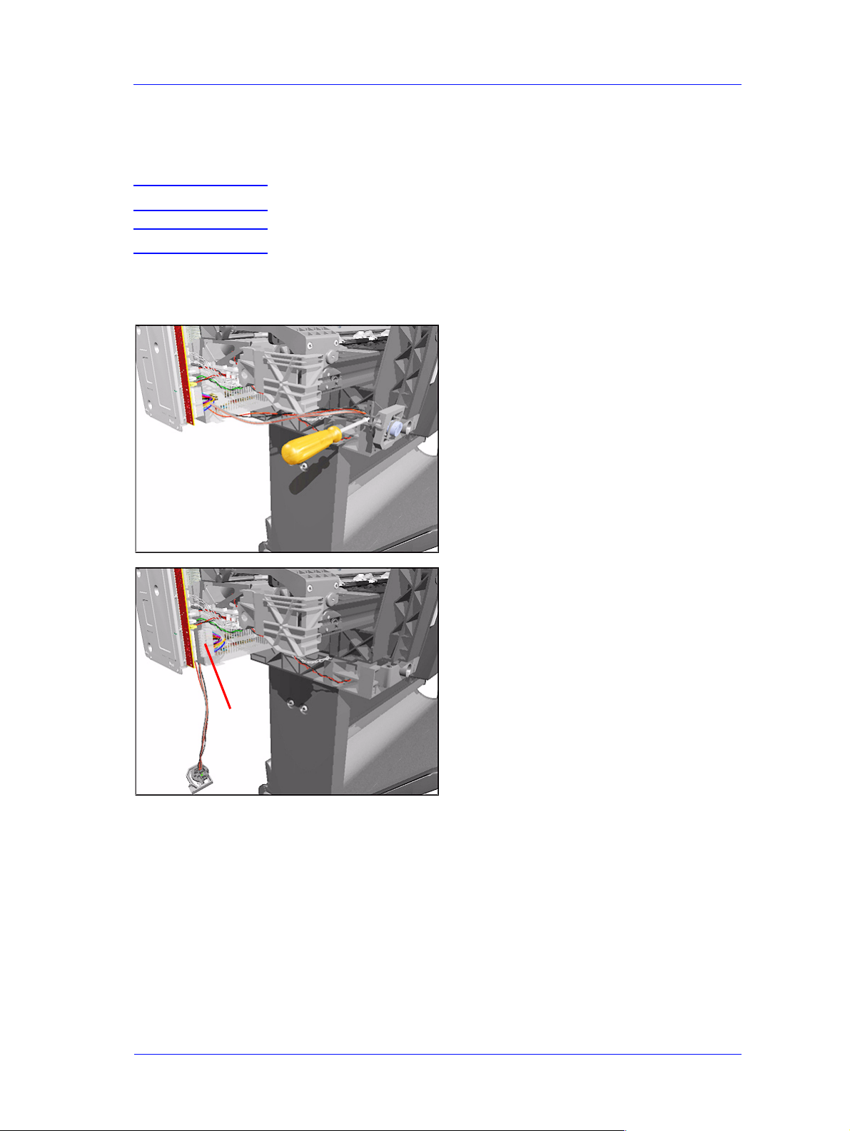
4. Disconnect the Paper-Axis Motor
Cables from the Electronics Module.
5. Remove 2 T-15 screws (Type J) from
the Paper-Axis Motor.
NOTE Make sure that you keep hold
of the Paper-Axis Motor
when removing the screws,
otherwise the Motor could
fall and be damaged.
8-84
HP DesignJets 500 and 800 Series Printers Service Manual
Page 85

Removal and Installation
6. Remove the Paper-Axis Motor
(including the cables).
HP DesignJets 500 and 800 Series Printers Service Manual
8-85
Page 86

Removal and Installation
Drive Roller
Removal
WARNING Switch off the printer and remove the power cord.
1. Remove the Spindle.
2. Remove the Left Hand Cover - Refer
to Page 8-5.
3. Remove the Right Hand Cover - Refer
to Page 8-7.
4. Remove the Left and Right Trims.
5. Remove the Front Panel - Refer to
Page 8-9.
6. Remove the Top Cover and Window Refer to Page 8-10.
7. Remove all the Media Deflectors Refer to Page 8-11.
8. Remove the Back Platen (make sure
the Lever is in the UP position) Refer to Page 8-17.
9. Remove the Media Sensor - Refer to
Page 8-19.
10. Remove the Spittoon - Refer to Page
8-23.
11. Remove the Cutter Assembly - Refer
to Page 8-32.
12. Remove the Cutter Guide Bracket Refer to Page 8-36.
13. Remove the Drive Roller Encoder
Sensor - Refer to Page 8-38.
14. Remove the Ink Supply Station Refer to Page 8-48.
15. Remove the Cutter Guide - Refer to
Page 8-55.
8-86
HP DesignJets 500 and 800 Series Printers Service Manual
Page 87

Removal and Installation
16. Disconnect the Pinch-Arm Sensor
Cable from the Interconnect PCA.
17. Disconnect the Paper-Axis Motor
Cables and the Vacuum Fan Cable
from the Electronics Module.
18. Remove 1 screw (T-10) from the
Grounding Strip.
HP DesignJets 500 and 800 Series Printers Service Manual
8-87
Page 88

Removal and Installation
19. Remove 1 screw (T-15) from the
Right Back Trim and remove trim.
20. Remove 1 screw (T-15) from the Left
Back Trim and remove trim.
21. Remove 4 screws (T-25) that secure
the Top Part of the Printer to the
Bottom Part from the Left Hand Side.
8-88
HP DesignJets 500 and 800 Series Printers Service Manual
Page 89

Removal and Installation
22.
Remove 4 screws (T-25) that secure
the Top Part of the Printer to the
Bottom Part from the right hand side.
23. Make sure the Media Lever is in the
UP Position and lift the complete Top
Part of the Printer away from the
Bottom Part.
NOTE The T op Part of the Printer is
very heavy so 2 people should
perform this step.
24. Remove 1 screw (T-15) from the Axle
Spring.
HP DesignJets 500 and 800 Series Printers Service Manual
8-89
Page 90

Removal and Installation
25. Remove the Axle Spring.
NOTE Be very careful when
removing the Axle Spring
because you could damage
the Encoder Disc.
26. Remove the Encoder Disc Cover.
27. Release the levers on both ends of the
Drive Roller.
8-90
HP DesignJets 500 and 800 Series Printers Service Manual
Page 91

Removal and Installation
28. Lift Drive Roller out of the Printer.
NOTE Make sure you take care
when lifting the Drive Roller
because the Encoder Disc
could get damaged.
HP DesignJets 500 and 800 Series Printers Service Manual
8-91
Page 92

Removal and Installation
Gear Assemblies
Removal
WARNING Switch off the printer and remove the power cord.
1. Remove the Spindle.
2. Remove the Left Hand Cover - Refer
to Page 8-5.
3. Remove the Right Hand Cover - Refer
to Page 8-7.
4. Remove the Left and Right Trims.
5. Remove the Front Panel - Refer to
Page 8-9.
6. Remove the Top Cover and Window Refer to Page 8-10.
7. Remove all the Media Deflectors Refer to Page 8-11.
8. Remove the Back Platen (make sure
the Lever is in the UP position) Refer to Page 8-17.
9. Remove the Media Sensor - Refer to
Page 8-19.
10. Remove the Spittoon - Refer to Page
8-23.
11. Remove the Cutter Assembly - Refer
to Page 8-32.
12. Remove the Cutter Guide Bracket Refer to Page 8-36.
13. Remove the Drive Roller Encoder
Sensor - Refer to Page 8-38.
14. Remove the Ink Supply Station Refer to Page 8-48.
15. Remove the Cutter Guide - Refer to
Page 8-55.
8-92
16. Remove the Paper-Axis Mot or - Refer
to Page 8-84.
HP DesignJets 500 and 800 Series Printers Service Manual
Page 93

Removal and Installation
17. Remove the Drive Roller - Refer to
Page 8-86.
18. Remove the 2 locking pins from the
Gears.
19. Remove the Gears.
HP DesignJets 500 and 800 Series Printers Service Manual
8-93
Page 94

Removal and Installation
8-94
HP DesignJets 500 and 800 Series Printers Service Manual
 Loading...