

Page 1
Removal and Installation8
Screw Types 8-4
Top Cover Assembly 8-5
Left Hand Cover 8-6
Right Hand Cover 8-10
Front Panel Assembly 8-14
Left Rear Cover 8-15
Right Rear Cover 8-16
Extension Cover (60" Model only) 8-17
Media Lever Assembly 8-18
Right Hand Trim 8-20
Left Hand Trim 8-22
Back Cover 8-23
Ink Tubes System 8-25
EMC Covers 8-32
Encoder Strip 8-34
Trailing Cable 8-36
Tensioner Assembly 8-42
Carriage Assembly and Belt 8-46
Line Sensor 8-53
Scan-Axis Motor 8-57
Cutter Assembly 8-60
Ink Suppl y St ation (ISS) 8-64
Air Pressurization System (APS) 8-67
Service Station Assembly 8-69
Drop Detector Assembly 8-72
Hard Disk Drive (HDD) 8-74
LAN Card 8-76
Memory and BootROM DIMM’s 8-77
Electronics Module Cover 8-79
Main PCA 8-81
PCI-to-IDE PCA 8-85
Power Supply Unit (PSU) 8-88
Ink Suppl y St ation (ISS) PCA 8-91
Ink Leak Detector - If Present (Only Applicable to the 5000 Series) 8-93
Cooling Fans 8-95
Electronics Module (as one complete Assembly) 8-97
Pinch-Wheels 8-98
Pinch-Wheel Cam 8-100
Vacuum Fan 8-103
Paper-Axis Motor Assembly 8- 105
Booster Fan 8-108
Media Sensor 8-109
Entry Roller 8-111
Center Guide Assembly 8-112
Drive Roller Gear 8-114
Front Platen Assembly (Only Applicable to the 5000 Series) 8-115
Center Platen Assembly 8-117
Deflectors (Only Applicable to the 5000 Series) 8-119
Heater Assembly (Only Applicable to the 5500 Series) 8-120
Tube Guide Door 8-124
HP DesignJet 5000 and 5500 Series Printers Service Manual
8-1
Page 2

Removal and Installation
Introduction
This chapter is a step by step guide to the removal and installation of the key components
in the Printer. You may find it useful to tick off the steps as they are performed. Use the
illustration at each procedure to identify the parts referred to in the text.
The procedur es appear in or der of removal. So the whole machine can be stripped down by
starting at the beginning of this chapter and working through the subsequent procedures.
NOTE
THE INSTRUCTIONS IN THIS CHAPTER APPLY BOTH TO
THE DESIGNJET 5000 AND 5500 SERIES UNLESS
OTHERWISE NOTED. EVEN THOUGH THE ILLUSTRATIONS
ARE SHOWN USING THE DESIGNJET 5000 SERIES, THESE
ARE ALSO APPLICABLE TO THE DESIGNJET 5500 SERIES.
NOTE Before using this chapter to remove and/or replace a component
or assembly, always make sure that you have performed the
relevant service test for each component as described in 4,
Service Tests and Utilities. If the test passes you will not need to
replace the component.
NOTE To install a component perform the removal procedures in
reverse order unless a specific installation procedur e is provided.
NOTE After removing and/or replacing a component, the relative
procedure will state whether any calibrations and/or tests are
required (Chapter 5, Service Calibrations).
Safety Precautions
(Safety symbols - Immediately after the table of contents.)
Review WARNING and CAUTION symbols and instructions before you service the Printer.
Follow these warnings and cautions for your protection an d to avoid damaging the Printer.
WARNING Serious shock hazard leading to death or injury may result if you
do not take the following precautions:
Ensure that the ac power outlet (mains) has a prote ctive earth
(ground) terminal.
Switch the printer off, and di sconnect it from the power source
prior to performing any maintenance.
Prevent water or other liquids from running onto electrical
components or circuits, or through openings in the module.
8-2
HP DesignJet 5000 and 5500 Series Printers Service Manual
Page 3
Removal and Installation
Electrostatic Discharge (ESD) Precautions
To prevent damage to the Printer circuits from high-voltage electrostatic discharge
(ESD):
1. Do not wear clothing that is subject to static build-up.
2. Do not handle integrated circuits (ICs) in carpeted areas.
3. Do not remove an IC or a printed circuit assembly (PCA) from its conductive foam
pad or conductive packaging until you are ready to install it.
4. Ground (earth) your body while disassembling and working on the Printer.
5. After removing a cover from the Printer, attach an earthing (ground) lead between
the PCA common and earth ground. Touch all tools to earth ground to remove static
charges before using them on the Printer.
6. After removing any PCA from the Printer, pl ace it on a conductive foam pad or into
its conductive packaging to prevent ESD damage to any ICs on the PCA.
Required Tools
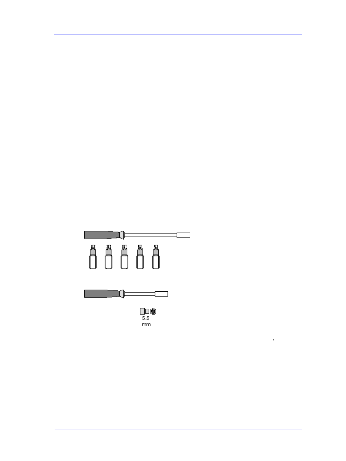
The following tools are required to disassemble and repair the Printer.
Long Torx Screwdriver with
the indicated attachments
T8 T10 T15 T20
T25
Nut driver with the
indicated attachments
Small flat-blade screwdriver
HP DesignJet 5000 and 5500 Series Printers Service Manual
8-3
Page 4

Removal and Installation
Screw Types
WARNING Chassis screws have a copper washer and should never be
removed.
Type Torx Length
(mm)
Head Type Thread Type Part Number
A T-20 17 Pan Taptite 0515-1743
B T-15 12 Pan Machined 0515-0382
C T-20 10 Pan Taptite 0515-2282
D T-15 12.5 Pan Washer Plastite 0515-3040
E T-15 12.7 Pan Plastite 0624-0769
F T-15 20 Pan Plastite 0624-0771
G T-8 12.7 Pan Plastite 0624-0768
H T-15 9.5 Pan Plastite 0515-2981
I T-10 7.5 Flat Taptite 0515-2984
J T-15 27.4 Pan Machined 0515-2986
K T-10 8 Pan Taptite 0515-2200
L T-20 14 Pan Taptite 0515-2248
M T-15 - Flat Taptite 0515-2250
N T-15 24 Flat Machined C6071-20026
O T-15 10 Pan Washer Machined 0515-0380
P T-10 8 Pan Machined 0515-2246
Q T-20 10 Pan Washer Taptite 0515-2278
R T-10 8 Flat Countersunk 2200-1294
S T-25 54 Pan Machined C6071-20005
T T-20 20 Pan Machined C3180-20001
U T-25 10 Pan Taptite 0515-4268
V T-8 14 Pan Machined 0624-0737
8-4
HP DesignJet 5000 and 5500 Series Printers Service Manual
Page 5
Removal and Installation
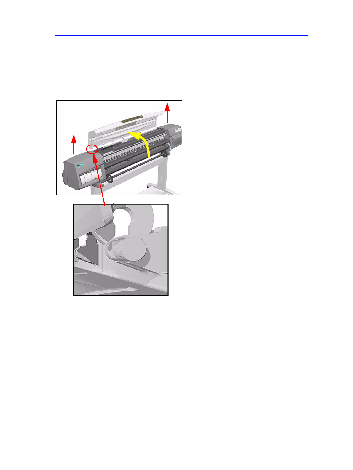
Top Cover Assembly
Removal
WARNING Switch off the Printer and remove the power cable.
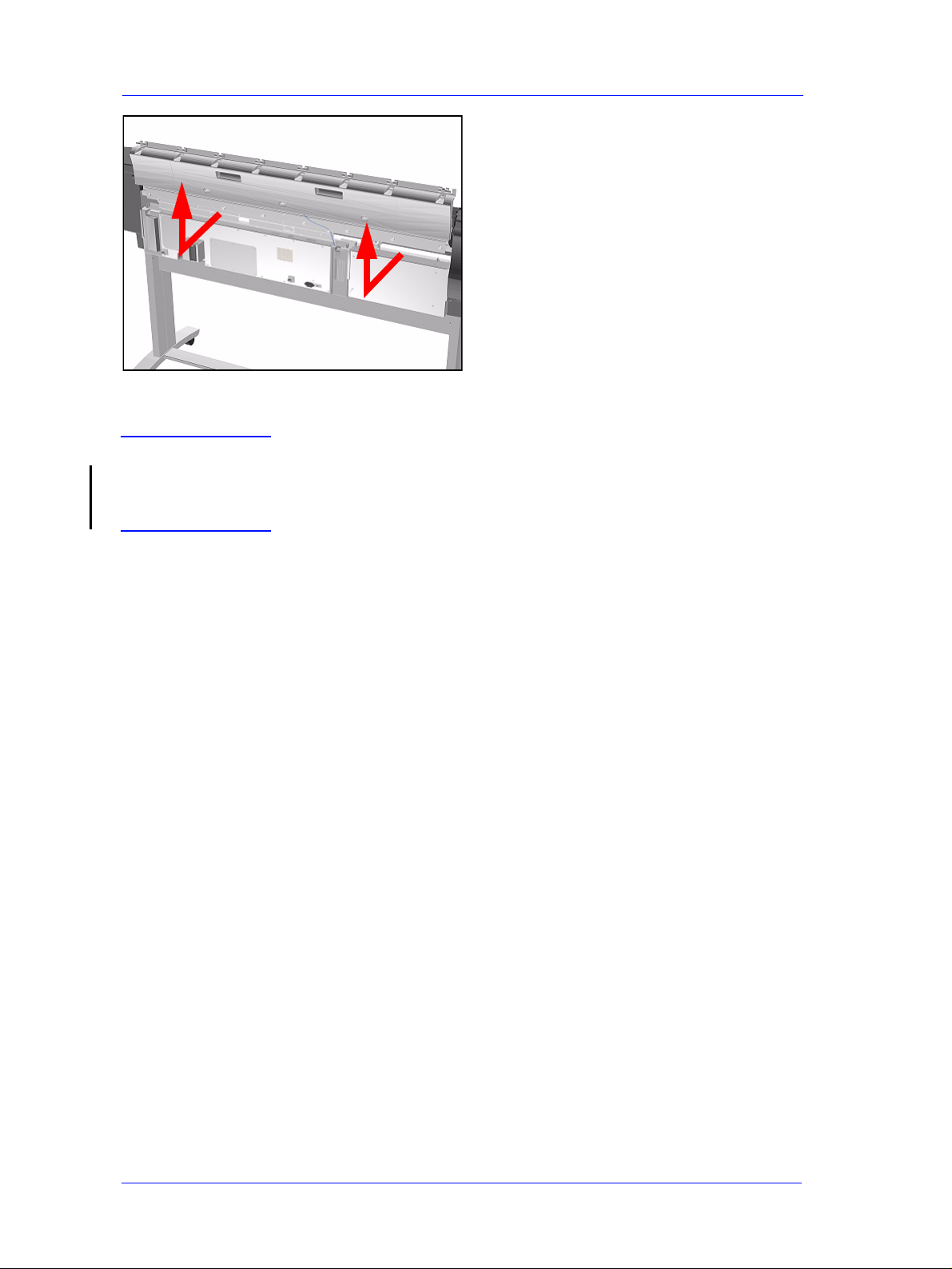
1. Open the Top Cover and lift UP and
remove from Printer (see detail of
hinge mechanism below).
NOTE Detail of hinge mechanism.
HP DesignJet 5000 and 5500 Series Printers Service Manual
8-5
Page 6
Removal and Installation
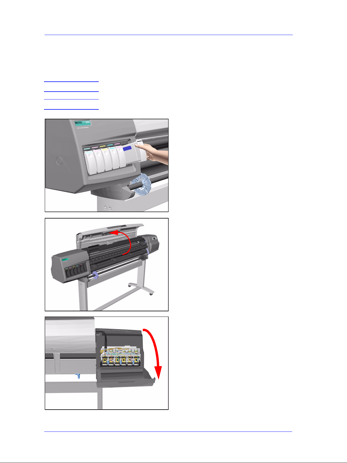
Left Hand Cover
Removal
WARNING Switch off the Printer and remove the power cable.
NOTE Refer to the table on Page 8-4 for information on screw types.
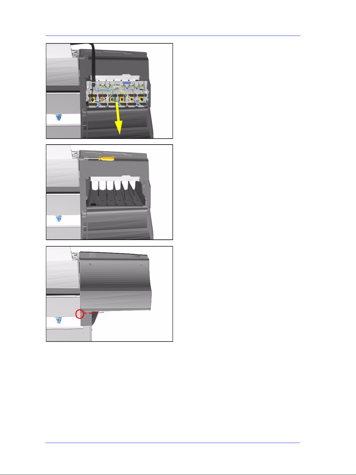
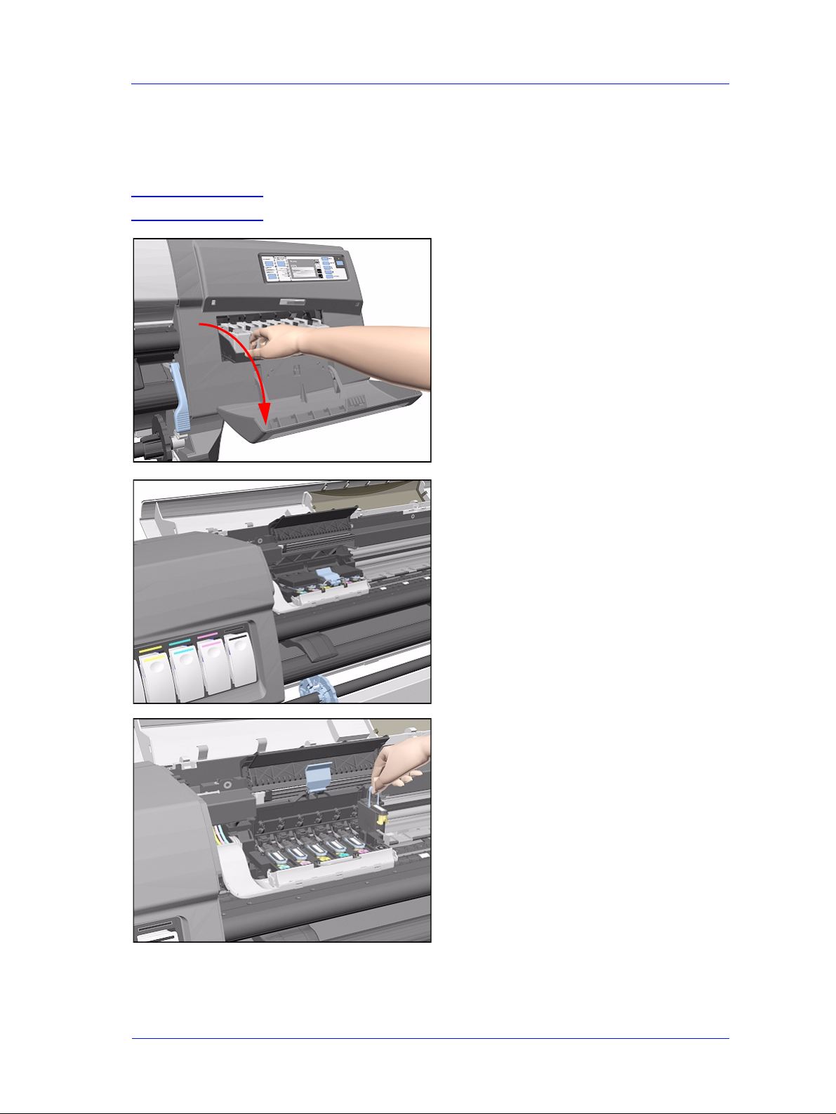
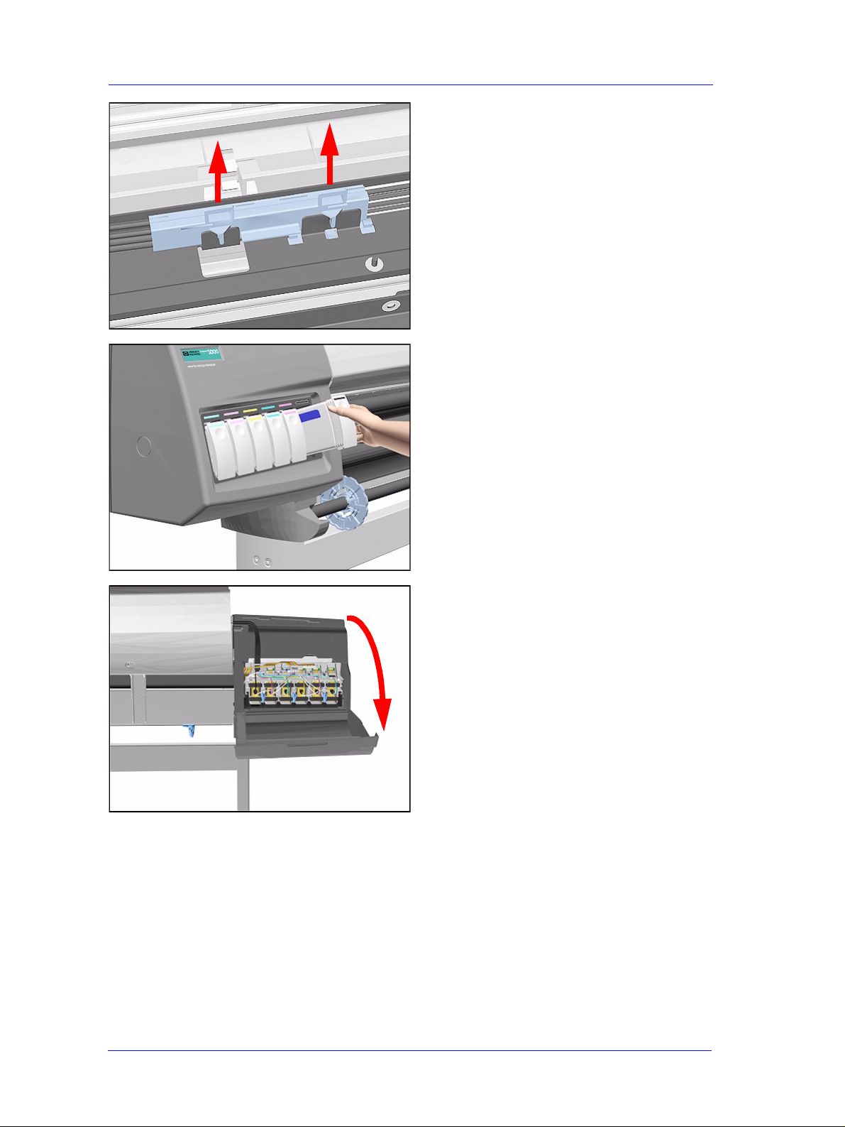
1. Remove ALL the Ink Cartridges from
the Printer.
2. Open the Top Cover.
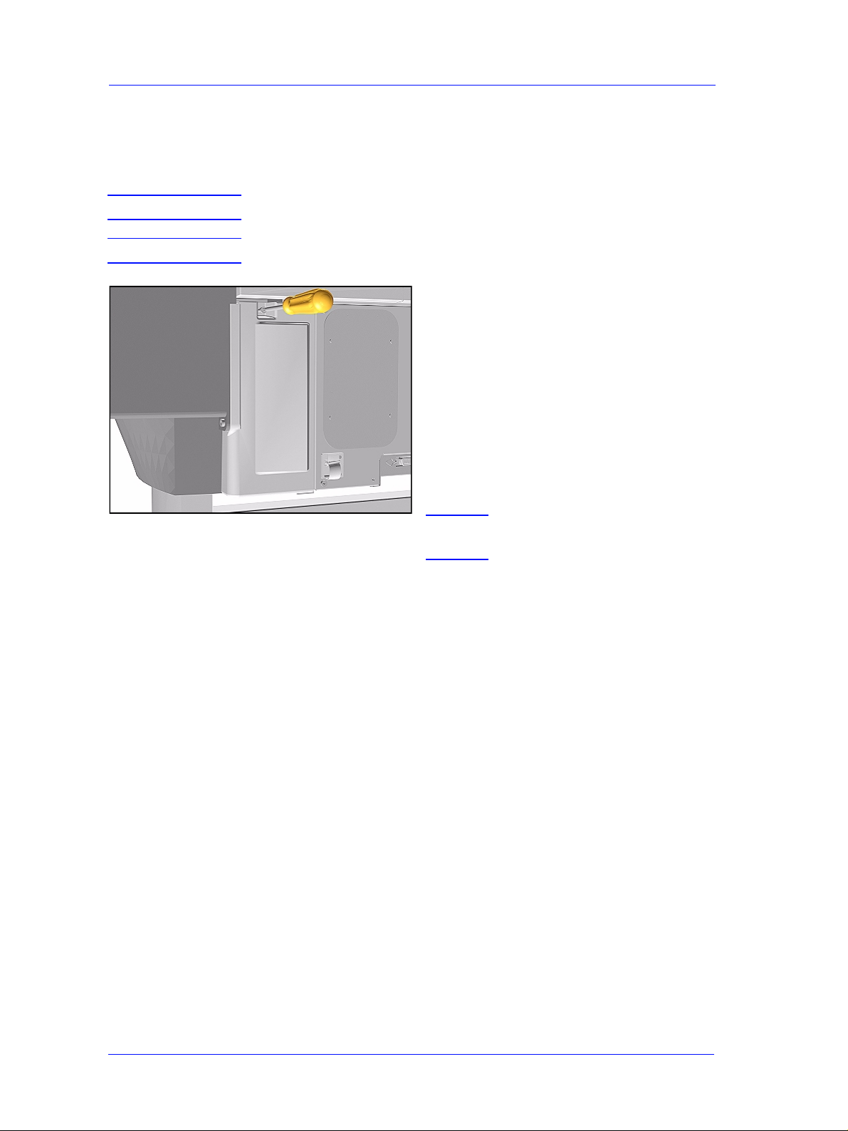
3. Open the door at the back of the Left
Hand Cover.
8-6
HP DesignJet 5000 and 5500 Series Printers Service Manual
Page 7

Removal and Installation
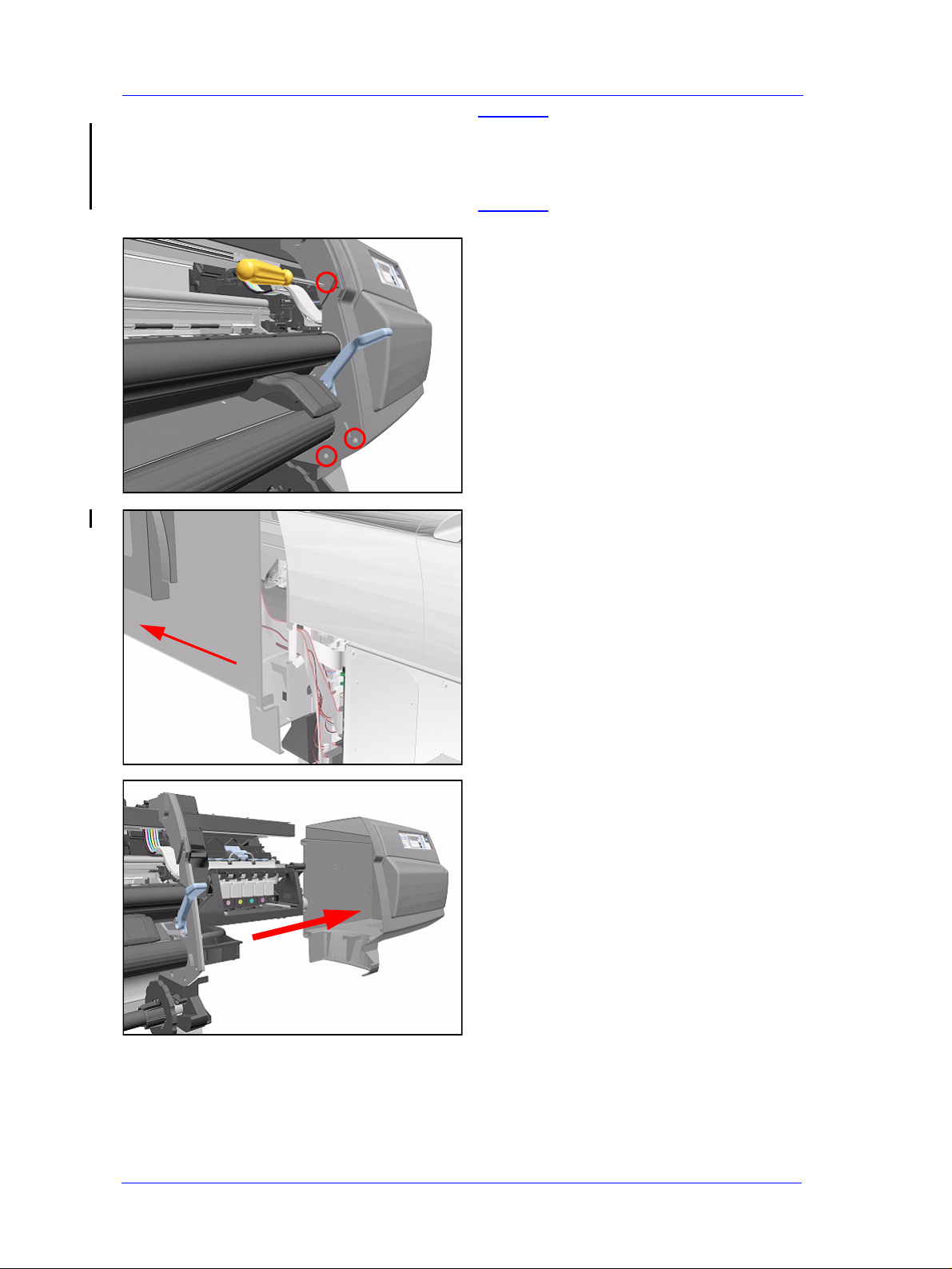
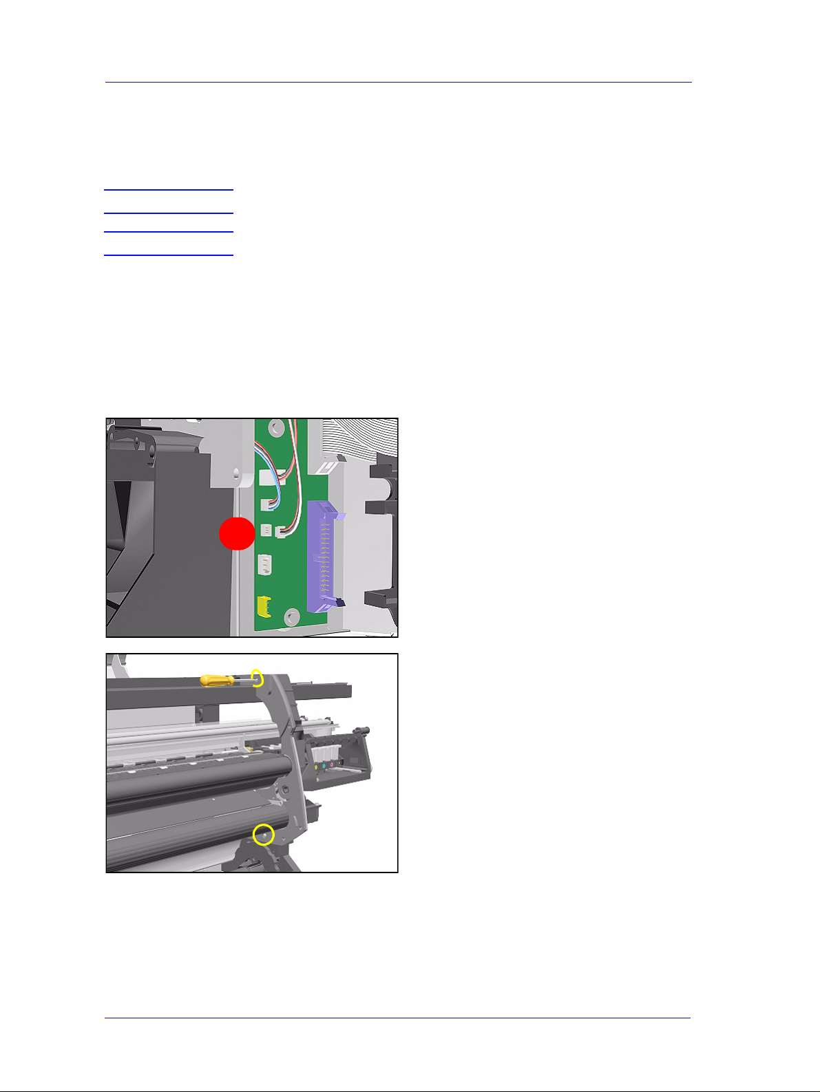
4. Disconnect the Electrical Cable from
the rear of the Ink Cartridge Tube
Connector.
5. Disconnect the Air Tube.
1
2
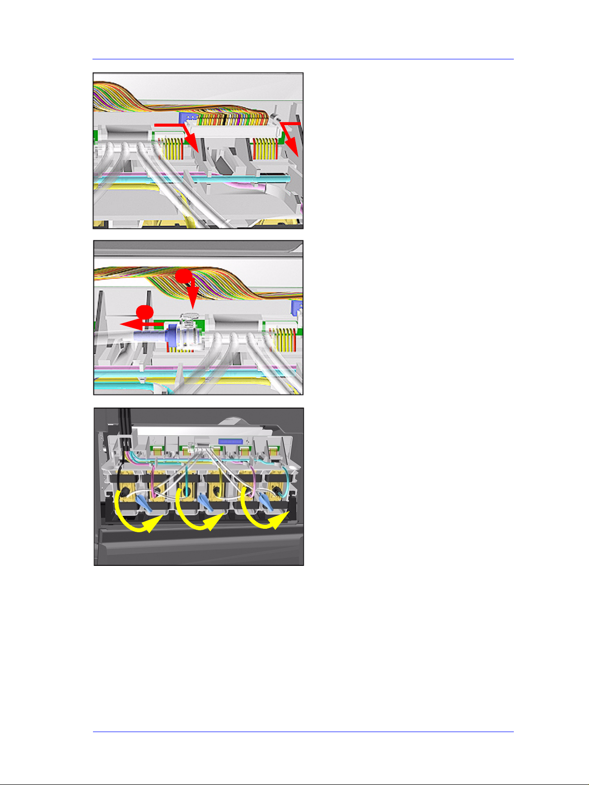
6. Twist the 3 latches at the rear of the
Ink Cartridge Tube Connector and
release the complete Assembly.
HP DesignJet 5000 and 5500 Series Printers Service Manual
8-7
Page 8
Removal and Installation
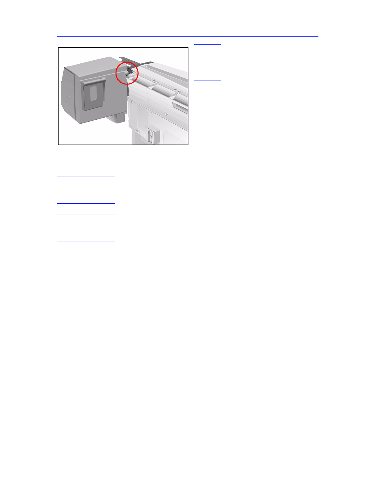
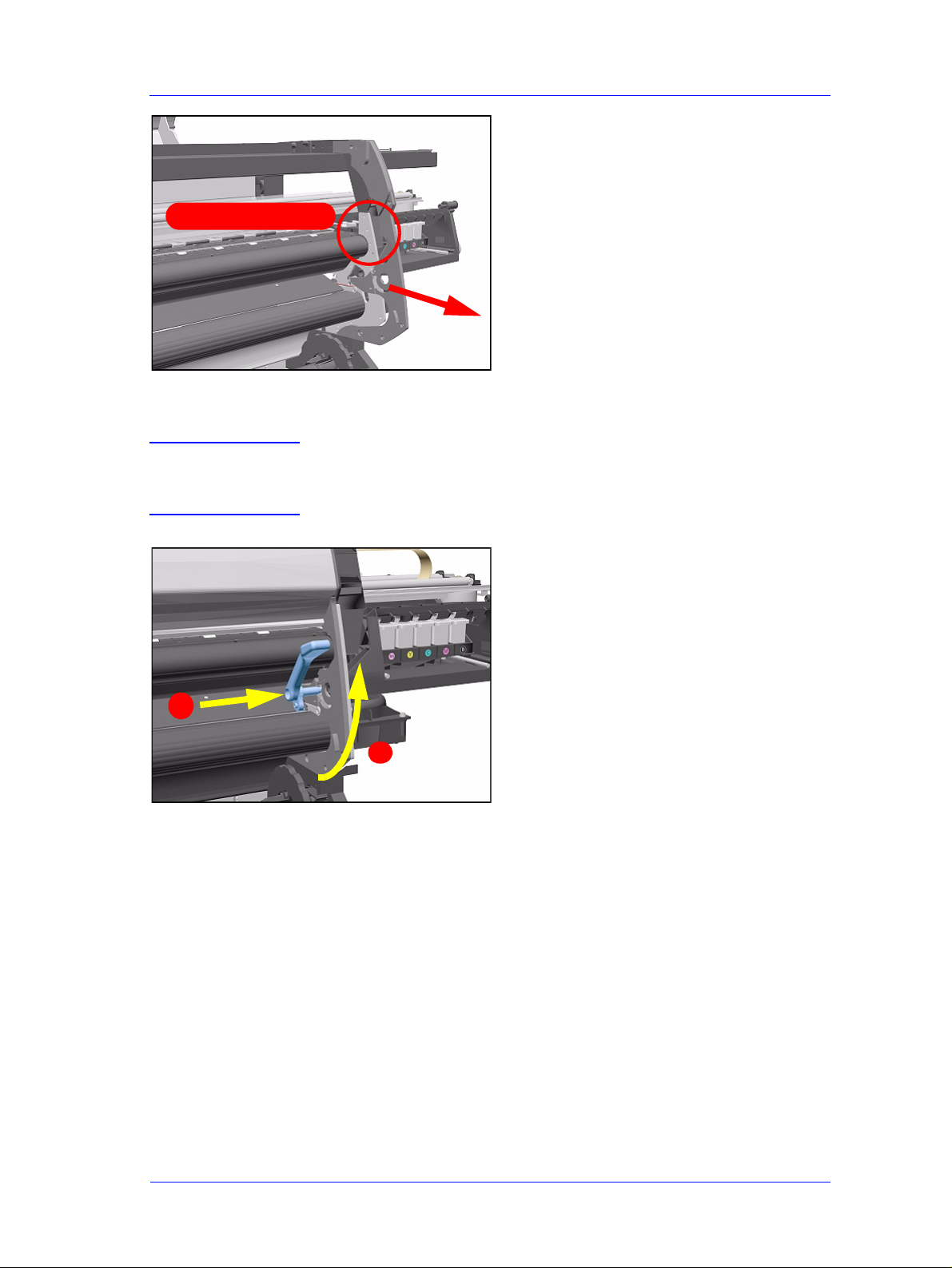
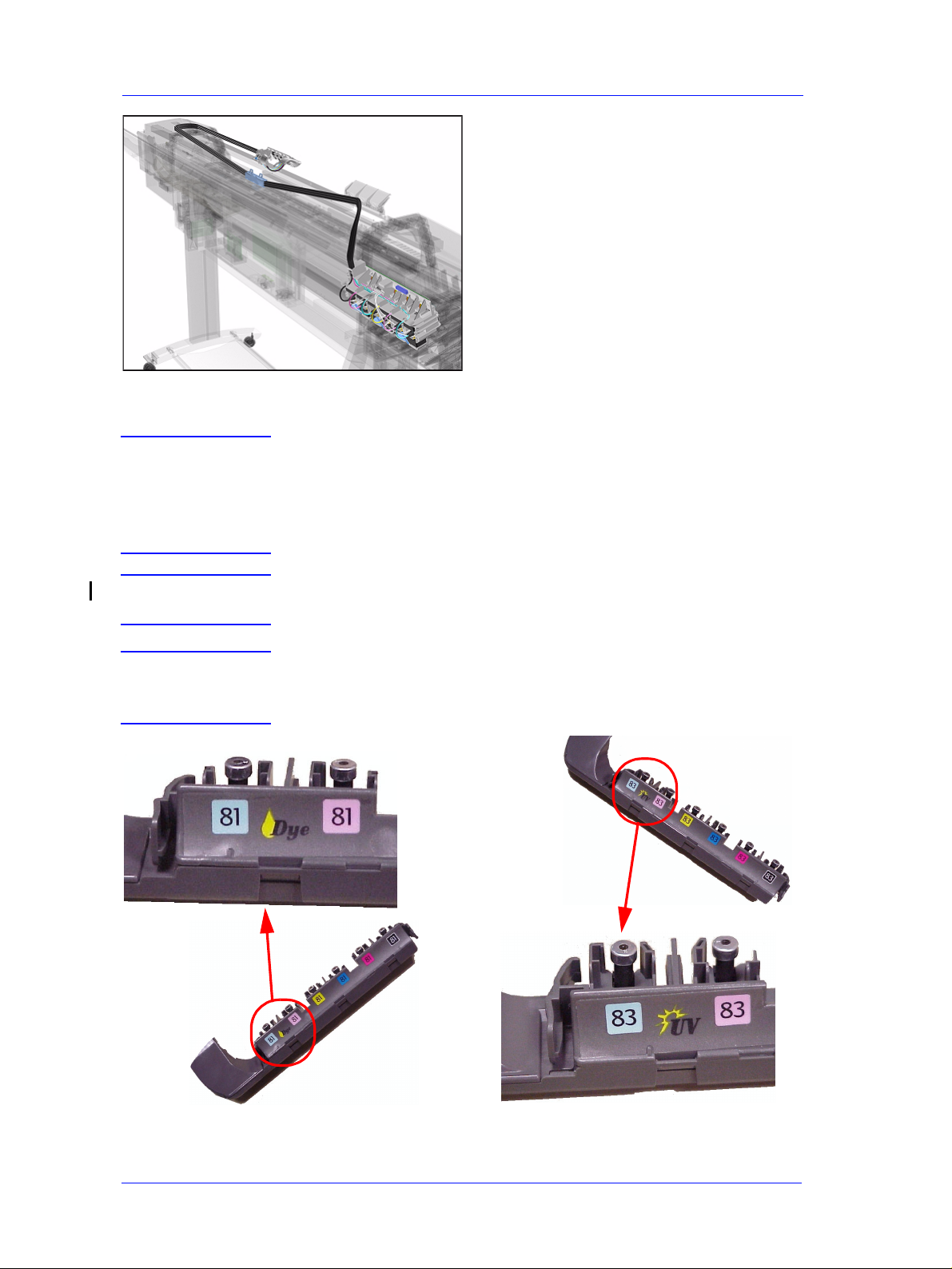
7. Remove the Ink Cartridge Tube
Connector and place safely on the
window.
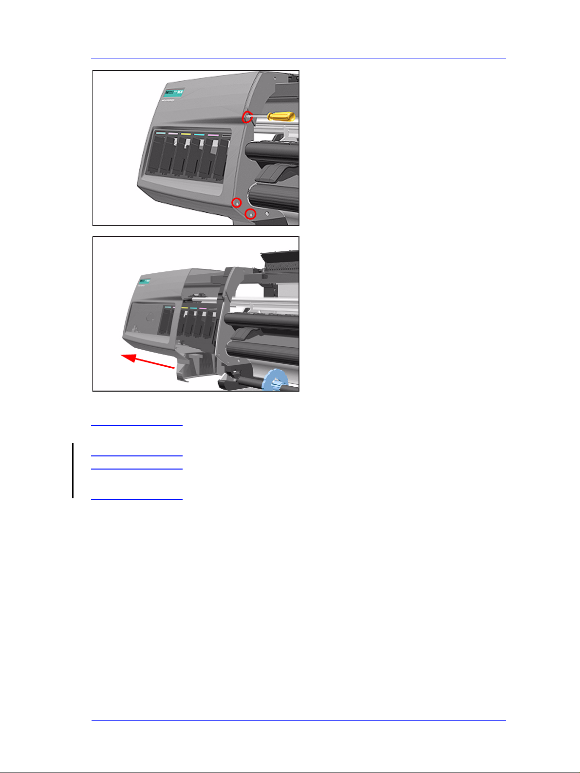
8. Remove 1 T-15 screw (Type F) from
the Left Hand Cover (rear).
9. Close the Left Back door and remove
1 T- 25 screw (Type U) from bottom
side (rear) of Left Hand Cover.
8-8
HP DesignJet 5000 and 5500 Series Printers Service Manual
Page 9
Removal and Installation
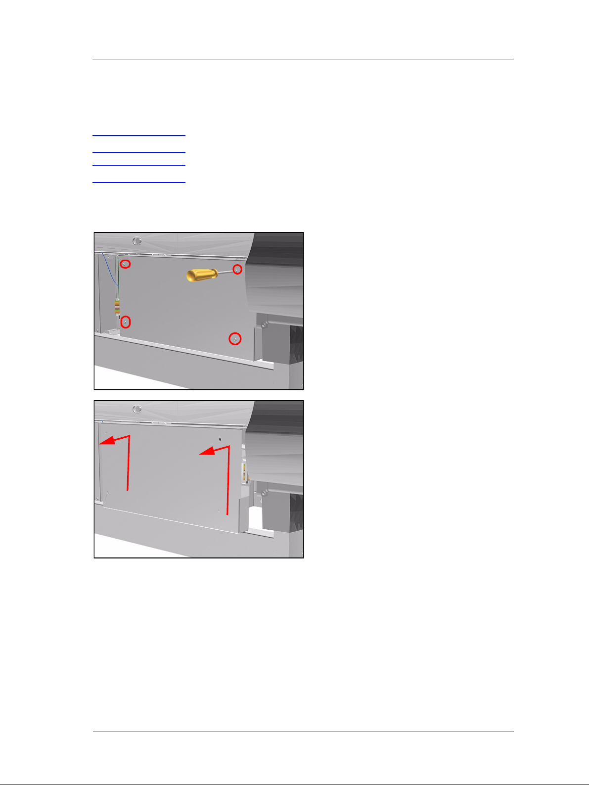
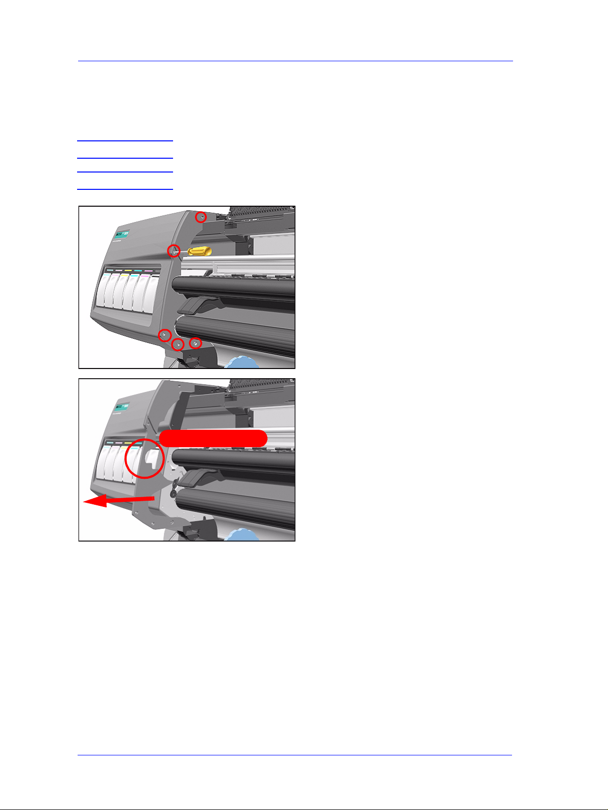
10. Remove 3 T-15 screws (Type F) from
the Left Hand Cover (front).
11. Remove the Left Hand Cover from the
Printer.
Installation of Left Hand Cover
WARNING When handling the Tubes make sur e you do not damage the m by
twisting.
WARNING When inserting the Left Hand Cover, be careful not to pinch/
twist the air tube or the electrical cable.
HP DesignJet 5000 and 5500 Series Printers Service Manual
8-9
Page 10
Removal and Installation
Right Hand Cover
Removal
WARNING Switch off the Printer and remove the Power Cord.
WARNING T o r emove the Right Hand Cover you must open the Right Cover
door and push in the Printhead Cleaner Carriage.
NOTE Refer to the table on Page 8-4 for information on screw types.
1. Remove the Right Rear Cover - Refer
to Page 8-16.
2. Remove the Ferrite (if present) and
disconnect the Front Panel cable from
the Main PCA (P24) from the left side
of the Electronics Module.
P29
P30
P24
3. On the Main PCA, disconnect the
Aerosol Fan cable from position P30
and the service station door from
position P29.
8-10
HP DesignJet 5000 and 5500 Series Printers Service Manual
Page 11
Removal and Installation
4. Remove 1 T-15 screw (Type F) and 1
T-25 screw (Type U) (bottom) from
the rear of the Right Hand Cover.
5. Open the Top Cover.
6. Raise the Media Lever.
HP DesignJet 5000 and 5500 Series Printers Service Manual
8-11
Page 12
Removal and Installation
NOTE Take care not to drop the
Cover when removing the
screws. Support the Cover
throughout the next step.
7. Remove 3 T-15 (Type F) screws from
the front of the Right Hand Cover.
8. To release the cables, carefully pull
out the Right Hand Cover until the
cables can be accessed.
8-12
9. Remove the Right Hand Cover.
HP DesignJet 5000 and 5500 Series Printers Service Manual
Page 13
Removal and Installation
TIP To check cor rect functioning
of serviced parts on the
Printer axis you can do the
following:
a Reinsert the top T -15 screw (Type F) at
the rear of the Printer.
b Hang the Cover on the screw.
c Connect all cables at the Rear of the
Right Cover and turn on the Printer.
Installation of Right Hand Cover
NOTE Make sure the Front Panel cable and the Aerosol Fan cables are
secured inside the Right Hand Cover with cable clamps and
retaining pins.
WARNING Make sure cables pass through slot at re ar of chassis on the right
hand side otherwise the Cover cannot be properly installed and
cables may be damaged.
HP DesignJet 5000 and 5500 Series Printers Service Manual
8-13
Page 14
Removal and Installation
Front Panel Assembly
Removal
WARNING Switch off the Printer and remove the Power Cord.
1. Remove Right Rear Cover - Refer to
Page 8-15.
2. Remove Right Hand Cover - Refer to
Page 8-10.
3. Disconnect the cable from Front
Panel.
Lift towards you
4. Unclip Front Panel supports inside the
Right Hand Cover and remove.
8-14
HP DesignJet 5000 and 5500 Series Printers Service Manual
Page 15
Removal and Installation
Left Rear Cover
Removal
WARNING Switch off the Printer and remove the Power Cord.
NOTE Refer to the table on Page 8-4 for information on screw types.
1. Remove one T -15 screw (Type B)
from the Left Rear Cover.
NOTE Support the Cover as it is
released.
2. Remove the Left Rear Cover.
HP DesignJet 5000 and 5500 Series Printers Service Manual
8-15
Page 16
Removal and Installation
Right Rear Cover
Removal
WARNING Switch off the Printer and remove the Power Cord.
NOTE Refer to the table on Page 8-4 for information on screw types.
1. Remove one T -15 screw (Type B)
from the Right Rear Cover.
NOTE Support the Cover as it is
released.
2. Remove the Right Rear Cover.
8-16
HP DesignJet 5000 and 5500 Series Printers Service Manual
Page 17
Removal and Installation
Extension Cover (60" Model only)
Removal
WARNING Switch off the Printer and remove the Power Cord.
NOTE Refer to the table on Page 8-4 for information on screw types.
1. Remove the Left Rear Cover - Refer
to Page 8-15.
2. Remove 4 T -15 screws (Type B) from
the Extension Cover.
3. Lift the Cover and remove from the
Printer.
HP DesignJet 5000 and 5500 Series Printers Service Manual
8-17
Page 18
Removal and Installation
Media Lever Assembly
Removal
WARNING Switch off the Printer and remove the Power Cord.
NOTE Refer to the table on Page 8-4 for information on screw types.
1. Only applicable to the DesignJet
5000 Series - Remove the Deflector
closest to the Right Cover - Refer to
Page 8-119.
2. Remove the Right Hand Cover - Refer
to Page 8-10.
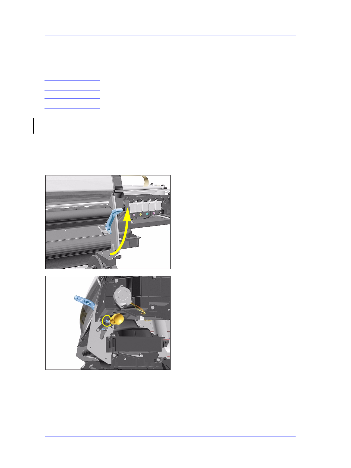
3. Raise the Media Lever.
8-18
4. Remove 1 T-15 screw (Type D) from
the support that attaches the Media
Lever to the Sideplate.
HP DesignJet 5000 and 5500 Series Printers Service Manual
Page 19
Removal and Installation
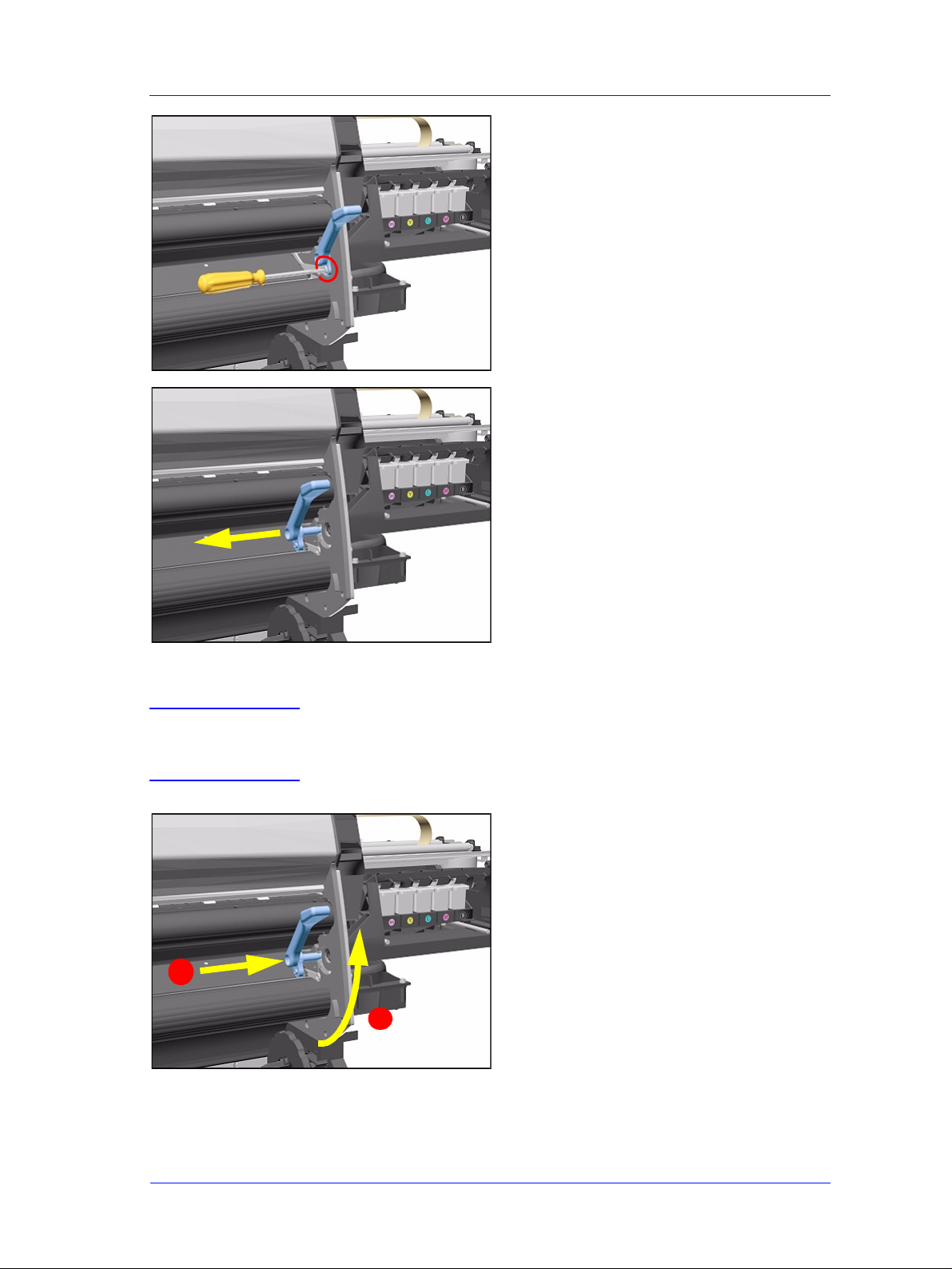
5. Remove 1 T-15 screw (Type H) that
attaches the Lever Arm to the Lever.
6. Remove the Media Lever.
Installation of the Media Lever Assembly
WARNING When installing the Media Lever, you must insert it in the Trim
and Sideplate in the UP position to avoid damaging the Lever
Spring in the Trim.
2
1
HP DesignJet 5000 and 5500 Series Printers Service Manual
8-19
Page 20
Removal and Installation
Right Hand Trim
Removal
WARNING Switch off the Printer and remove the Power Cord.
NOTE Refer to the table on Page 8-4 for information on screw types.
1. Remove Right Rear Cover - Refer to
Page 8-16.
2. Remove Right Hand Cover - Refer to
Page 8-10.
3. Remove Media Lever Assembly Refer to Page 8-18.
4. Disconnect the Sensors cable from
position P27 on the Main PCA.
P27
5. Remove 1 T -15 screws (Type F) and 1
T-20 (Type L) from the Right Hand
Trim.
8-20
HP DesignJet 5000 and 5500 Series Printers Service Manual
Page 21
Removal and Installation
6. Carefully remove the Right Hand
Trim.
Remove carefully
Installation of Right Hand Trim
WARNING When installing the Media Lever in the Trim, install with the
Lever in the UP position to avoid damaging the Lever spring in
the Trim.
2
1
HP DesignJet 5000 and 5500 Series Printers Service Manual
8-21
Page 22
Removal and Installation
Left Hand Trim
Removal
WARNING Switch off the Printer and remove the Power Cord.
NOTE Refer to the table on Page 8-4 for information on screw types.
1. Remove 4 T -15 screws (Type F) and 1
T-20 screw (Type L) from the Left
Hand Trim.
Remove carefully
2. Carefully remove the Left Hand Trim.
8-22
HP DesignJet 5000 and 5500 Series Printers Service Manual
Page 23
Removal and Installation
Back Cover
Removal
WARNING Switch off the Printer and remove the Power Cord.
NOTE Refer to the table on Page 8-4 for information on screw types.
1. Remove the Top Cover - Refer to
Page 8-5.
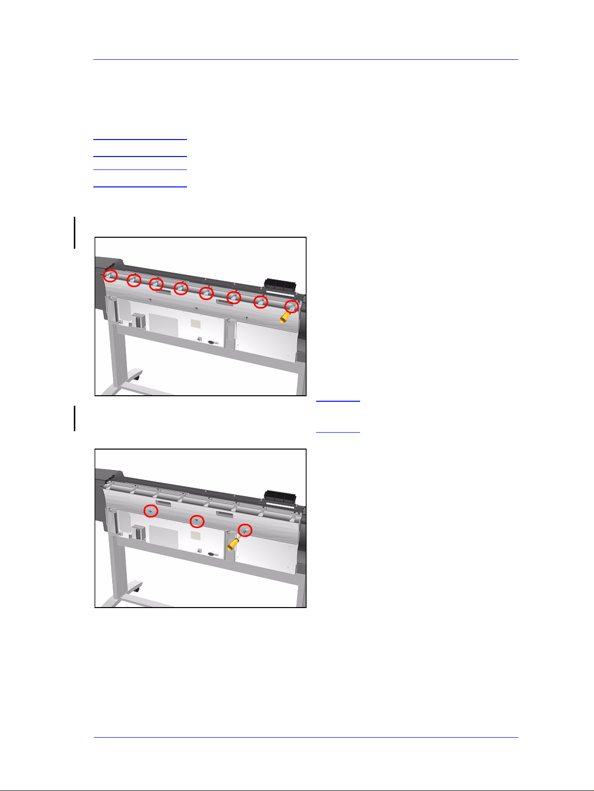
2. Remove the following (Type B)
screws from the upper part of the
Back Cover:
n 8 Screws (T-15) for the 60" Model.
n 6 Screws (T-15) for the 42" Model.
NOTE Support the Back Cover as it
is released.
3. Remove 3 T -15 screws (Type N) from
the lower part of the Back Cover.
HP DesignJet 5000 and 5500 Series Printers Service Manual
8-23
Page 24
Removal and Installation
4. Remove the Back Cover.
Installation of the Back Cover
NOTE If the Back Cover is replaced, remember to apply a new Printer
Label to the new Back Cover before it is installed. Once the new
label has been applied, copy the product number and serial
number onto it.
8-24
HP DesignJet 5000 and 5500 Series Printers Service Manual
Page 25
Removal and Installation
Ink Tubes System
Removal
WARNING Switch off the Printer and remove the Power Cord.
1. Open the Right Cover door and pull
out the Printhead Cleaner Carriage.
2. Open the Top Cover and pull the
Carriage out along the Printer to the
position shown.
3. Lift up the Carriage Cover and
remove ALL the Printheads and close
the Carriage Cover.
HP DesignJet 5000 and 5500 Series Printers Service Manual
8-25
Page 26
Removal and Installation
4. Slide the Carriage to the position
shown.
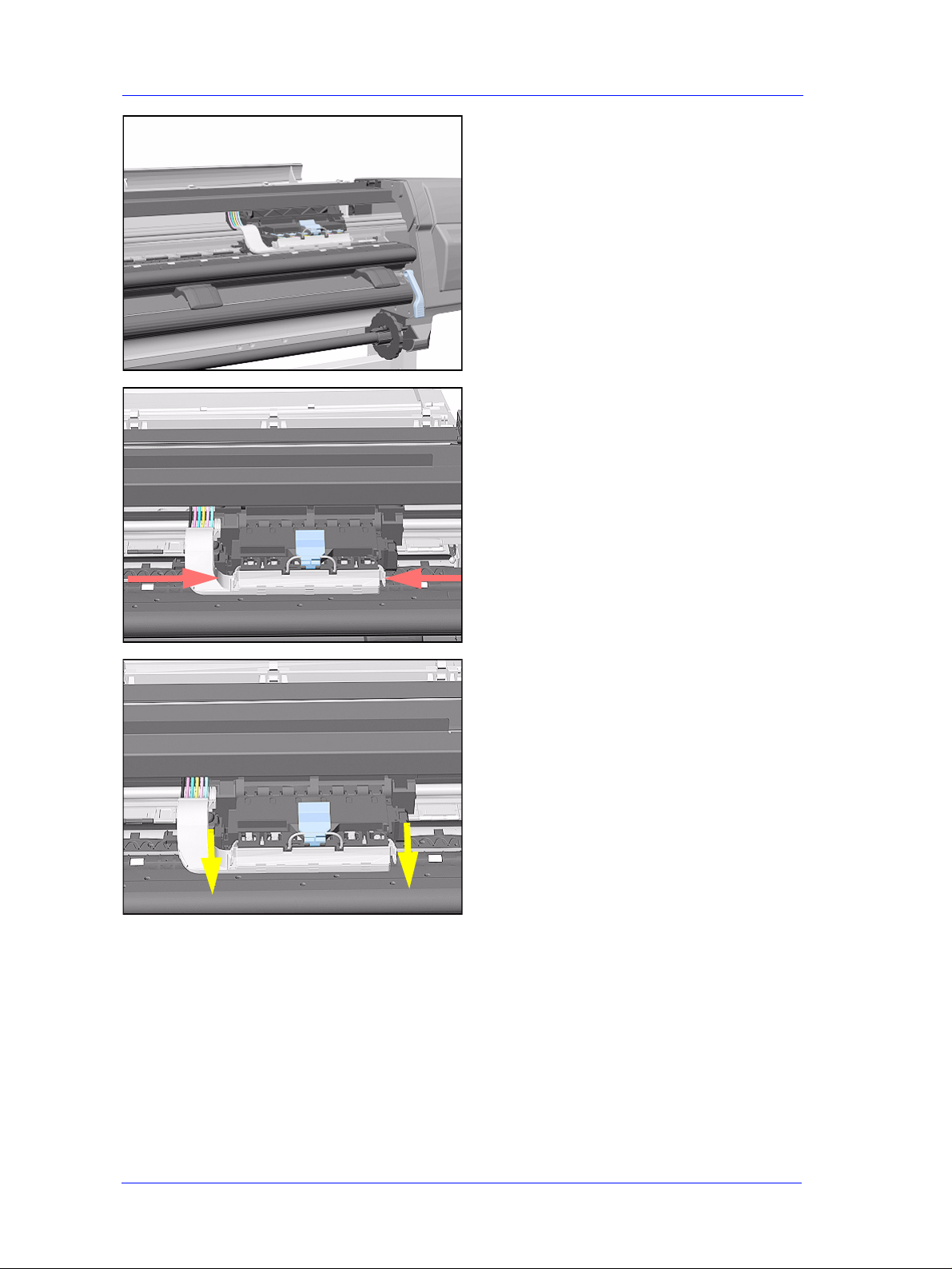
5. Push in the 2 retaining clips either side
of the Printhead Tube Connector.
6. Pull the Printhead Tube Connector
towards you.
8-26
HP DesignJet 5000 and 5500 Series Printers Service Manual
Page 27
Removal and Installation
7. Push the button to release the
Printhead Tubes in the Carriage.
8. Release the Retaining Clip by pulling
it away from the holding brackets.
9. Pull the Printhead Tube Connector up
between the two Tube Guides.
HP DesignJet 5000 and 5500 Series Printers Service Manual
8-27
Page 28
Removal and Installation
10. Lift out the blue Retaining Clip.
11. Remove ALL the Ink Cartridges from
the Printer.
12. Open the door at the back of the Left
Cover.
8-28
HP DesignJet 5000 and 5500 Series Printers Service Manual
Page 29
Removal and Installation
13. Disconnect the Electrical Cable from
the rear of the Ink Cartridge Tube
Connector.
14. Disconnect the Air Tube.
1
2
15. Twist the 3 latches at the rear of the
Ink Cartridge Tube Connector and
release the complete Assembly.
HP DesignJet 5000 and 5500 Series Printers Service Manual
8-29
Page 30
Removal and Installation
16. The complete assembly can now be
removed by sliding the Ink Cartridge
Connector out from the rear of the
Left Hand Cover.
Installation of Ink Tubes System
WARNING When installing the Ink Tubes System it is very important that
the Tubes are NOT TWISTED. Make sure that the Tubes are
correctly routed at the rear of the Left Cover and before
powering On the printer, check again that they are NOT
TWISTED.
NOTE Do not install NEW Ink Tubes System with Ink Cartridges that
indicate Low or Very Low ink levels.
NOTE Before installing the new Ink Tubes System, make sure that the
Ink Type (Dye or UV) of the Tubes is the same as the ones that
you are replacing.
8-30
HP DesignJet 5000 and 5500 Series Printers Service Manual
Page 31

Removal and Installation
NOTE When the Ink Tubes System is replaced, to restart the Printer
perform the following procedures.
1. Install the Setup Printheads (refer to
the User’s Guide).
2. Connect the Power Cable and turn on
the main Power Switch at the rear of
the Printer.
3. The Front Panel warns that there are
no Ink Cartridges installed.
INK STARTUP
Initializing Printer
Please wait 60 sec
4. Install the Ink Cartridges (refer to the
User’s Guide for details).
5. The Front Panel displays the message
shown.
6. Wait about 60 seconds for the next
instruction.
7. Remove the Setup Printheads from the
Printhead Carriage.
8. Install the Printheads and the
Printhead Cleaners (refer to the User’s
Guide for details).
HP DesignJet 5000 and 5500 Series Printers Service Manual
8-31
Page 32

Removal and Installation
EMC Covers
Removal
WARNING Switch off the Printer and remove the Power Cord.
NOTE Refer to the table on Page 8-4 for information on screw types.
NOTE The EMC Cover is composed of three parts; T op, Lower Left and
Lower Right. Procedures below describe removal of the EMC
Covers as; one assembly, the Top only , the Lower Right only . The
procedure you select depends on the part you want to access.
EMC Covers as one assembly
1. Remove the Top Cover - Refer to
Page 8-5.
2. Remove the Back Cover - Refer to
Page 8-23.
3. Remove Right Rear Cover - Refer to
Page 8-16.
4. Remove Left Rear Cover - Refer to
Page 8-15.
5. Remove Electronics Module - Refer
to Page 8-97.
6. Disconnect connector from Ink Leak
Detector and remove 1 T-15 screw
(Type B) to remove Ink Leak Detector
cable clamp.
NOTE The Ink Leak Detector is
NOT present in the
DesignJet 5500 Series and in
some DesignJet 5000 Series
printers.
8-32
HP DesignJet 5000 and 5500 Series Printers Service Manual
Page 33

Removal and Installation
7. Remove the following screws (Type
N) from the Top EMC Cover.
n 8 T-15 screws for the 60" Model.
n 6 T-15 screws for the 42" Model.
8. Loosen 4 T-15 screws (Type L) on
Lower Covers and remove all Covers
as one assembly.
Lower Right Cover
1. Do steps 1 to 5 of the EMC Covers as
one assembly procedure.
2. Remove 2 T-15 screws (Type B) and
loosen 2 T -15 bottom screws (Type L)
to remove cover.
Top EMC Cover
1. Do steps 1, 2 and 6 of the EMC
2. Remove the following screws (Type
3. Lift the Top EMC Cover off Printer.
HP DesignJet 5000 and 5500 Series Printers Service Manual
Covers as one assembly procedure.
B and N) screws from the Top EMC
Cover.
n 13 T-15 screws for 60" Model.
n 11 T-15 screws for 42" Model.
8-33
Page 34

Removal and Installation
Encoder Strip
Removal
WARNING Switch off the Printer and remove the Power Cord.
1. Remove the Left Hand Cover - Refer
to Page 8-6.
2. Remove the Right Hand Cover - Refer
to Page 8-10.
3. Remove the Top Cover - Refer to
Page 8-5.
4. Remove the Back Cover - Refer to
Page 8-23.
5. Remove the Top EMC Cover - Refer
to Page 8-32.
1. Apply Pressure
6. Remove the 5.5 mm nut from the left
hand side of the Printer that attaches
the Encoder Strip to the Spring Clip.
TIP The next step is performed
by putting pressure on the
Spring Clip as shown.
7. Release the Encoder strip from the
Spring Clip.
2. Release Encoder Strip
8-34
HP DesignJet 5000 and 5500 Series Printers Service Manual
Page 35

Removal and Installation
8. Remove the 5.5 mm nut from the right
hand side of the Printer.
9. Remove the Encoder Strip from the
Printer.
2 Pull strip out
1 Lift off pins
Installation of Encoder Strip
WARNING When Installing the Encoder Strip, make sure it is placed in the
Encoder Sensor on the rear of the Carriage Assembly as shown
below.
Insert Encoder Strip
HP DesignJet 5000 and 5500 Series Printers Service Manual
Encoder Sensor
8-35
Page 36

Removal and Installation
Trailing Cable
Removal
WARNING Switch off the Printer and remove the Power Cord.
NOTE Refer to the table on Page 8-4 for information on screw types.
1. Remove the Top Cover - Refer to
Page 8-5.
2. Remove the Right Rear Cover - Refer
to Page 8-16.
3. Remove the Right Hand Cover - Refer
to Page 8-10.
4. Remove the Left Hand Cover - Refer
to Page 8-6.
5. Slide the Carriage to the left side of
the Printer.
6. Unclip and remove the Carriage
Cover to access the Trailing Cable in
the Carriage.
8-36
HP DesignJet 5000 and 5500 Series Printers Service Manual
Page 37

Press down in
center to release
Removal and Installation
7. Carefully disconnect the Trailing
Cables (3) from the connectors in the
Carriage PCA.
NOTE Remove Trailing Cable
Ferrites if they fall into the
Carriage
n 3 for 60" Model
n 1 for 42" Model
8. Remove the Trailing Cables from the
Trailing Cable Holder.
TIP Press the Trailing Cables
firmly in the center to
release.
Slide out
9. Slide the Trailing Cable Guide out of
the Carriage.
HP DesignJet 5000 and 5500 Series Printers Service Manual
8-37
Page 38

Removal and Installation
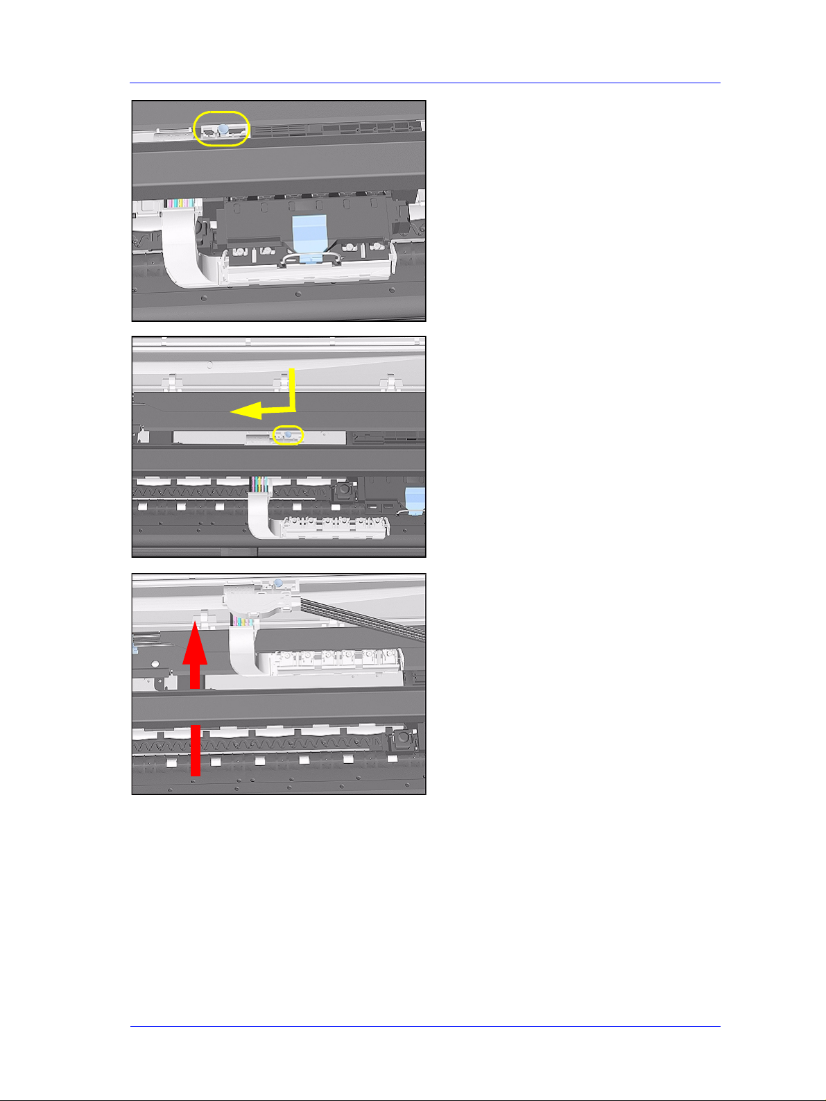
10. Carefully disconnect the Trailing
Cable from the Main PCA.
NOTE Unclip the Trailing Cable
when disconnecting from the
Main PCA.
11. Remove the T-20 screw (Type C)
from the Trailing Cable Clip on the
left.
NOTE There is a hole in the Tube
Guide to access the screw.
12. Remove 2 T-10 screws (Type I) from
the Trailing Cable Clip on the right.
NOTE Take care when removing
and inserting these screws as
they are easily damaged and
not easy to access.
8-38
HP DesignJet 5000 and 5500 Series Printers Service Manual
Page 39

Removal and Installation
13. Carefully lift the Clips and the
Trailing Cable from the Printer.
Installation of Trailing Cable
WARNING Do not install damaged Trailing Cables. If the Trailing Cable is
incorrectly installed or it is damaged, a "Power Supply Error
#1" message will appear on the Front Panel during ini tialization.
Check
edge
for
damage
WARNING When Installing the Trailing Cable, make sure you install it as
follows:
1. Install the Trailing Cable starting from
the Clip on the left as this will provide
a reference point for adjusting the
length of the Trailing Cable.
Left Clip
locating pin
HP DesignJet 5000 and 5500 Series Printers Service Manual
8-39
Page 40

Removal and Installation
2. Insert the Trailing Cable Guide into
the Carriage and connect the Trailing
Cables.
NOTE Remember to pass the
Trailing Cables through the
Ferrite(s).
n 3 for 60" Model.
n 1 for 42" Model.
3. Insert the Trailing Cable through the
Chassis slot next to the Trailing Cable
Clip on the right (see diagram in step
4).
Slot
Right Clip
locating pin
4. Place the Right Trailing Cable Clip in
position and adjust the length of the
Trailing Cable.
NOTE This clip has a locating pin so
make sure this is in position
and the Trailing Cable is the
right length before installing
the screw.
8-40
HP DesignJet 5000 and 5500 Series Printers Service Manual
Page 41

NO BUBBLES
Left Clip locating pin
Removal and Installation
TIP Make sure the Trailing Cable
is flat on the chassis without
bubbles.
Right
Clip
NOTE Check the cable and clips are
correctly installed by sliding
the carriage along the
Printer to see if it moves
freely.
Install with
edges straight on
Strip will not be
visible when
installed correctly
5. Connect the Trailing Cables to the
Main PCA.
NOTE Make sure the vertical strips
on Trailing Cable ends are
fully inserted inside the
connectors. The strip should
not be visible when inserted
correctly.
HP DesignJet 5000 and 5500 Series Printers Service Manual
8-41
Page 42

Removal and Installation
Tensioner Assembly
Removal
WARNING Switch off the Printer and remove the Power Cord.
NOTE Refer to the table on Page 8-4 for information on screw types.
1. Remove the Left Hand Cover - Refer
to Page 8-6.
2. Remove the Right Hand Cover - Refer
to Page 8-10.
3. Remove the 5.5 mm nut from the left
hand side of the Printer that attaches
the Encoder Strip to the Spring Clip.
1. Apply Pressure
2. Release Encoder Strip
TIP The next step is performed
by putting pressure on the
Spring Clip as shown.
4. Release the Encoder Strip from the
retaining pin on the Spring Clip.
8-42
HP DesignJet 5000 and 5500 Series Printers Service Manual
Page 43

Tighten screw
Tighten screw
Removal and Installation
5. Using a screwdriver, fully tighten the
Spring Release Screw to release the
tension on the Belt.
6. From the right-hand side, lift the
Tensioner Belt off the Scan-Axis
Motor.
7. Remove 1 T-15 screw (Type L) from
the Tensioner Assembly.
HP DesignJet 5000 and 5500 Series Printers Service Manual
8-43
Page 44

Removal and Installation
8. Remove the Belt Wheel on the left
side.
9. Remove the T ensioner Assembly from
the left-hand side.
8-44
HP DesignJet 5000 and 5500 Series Printers Service Manual
Page 45

Removal and Installation
Installation of Tensioner Assembly
NOTE Before installation, clean and oil the Slider Rods using the User’ s
Slider Rods Lubrification Kit (Refer to Page 9-8).
WARNING Be careful not to twist the Belt when installing the Tensioner
Assembly.
WARNING When installing the Enco der Strip, make sure it is in serted in the
Encoder Sensor on the rear of the Carriage Assembly as shown
below.
Insert Encoder Strip
Encoder Sensor
HP DesignJet 5000 and 5500 Series Printers Service Manual
8-45
Page 46

Removal and Installation
Carriage Assembly and Belt
Removal
WARNING Switch off the Printer and remove the power cord.
1. Remove the Left Hand Cover - Refer
to Page 8-6.
2. Remove the Right Rear Cover - Refer
to Page 8-16.
3. Remove the Right Hand Cover - Refer
to Page 8-10.
4. Remove the Tensioner Assembly Refer to Page 8-42.
5. Pull out Printhead Cleaner Carriage.
8-46
6. Slide Carriage Assembly to position
shown.
HP DesignJet 5000 and 5500 Series Printers Service Manual
Page 47

Removal and Installation
7. Lift up the Carriage Cover and
remove ALL the Printheads and close
the Carriage Cover.
8. Slide the Carriage along the Printer to
the position shown.
9. Push in the 2 retaining clips either side
of the Printhead Tube Connector.
HP DesignJet 5000 and 5500 Series Printers Service Manual
8-47
Page 48

Removal and Installation
10. Pull the Printhead Tube Connector
towards you.
11. Push the button to release the
Printhead Tubes in the Carriage.
12. Release the retaining clip by pulling it
away from the holding brackets.
8-48
HP DesignJet 5000 and 5500 Series Printers Service Manual
Page 49

Removal and Installation
13. Pull the Printhead Tube Connector up
between the two Tube Guides.
14. Slide the Carriage to the left side of
the Printer.
15. Unclip and remove the Carriage
Cover to access the Trailing Cable in
the Carriage.
HP DesignJet 5000 and 5500 Series Printers Service Manual
8-49
Page 50

Removal and Installation
Press down in
center to release
16. Carefully disconnect the Trailing
Cables (3) from the connectors in the
Carriage PCA.
NOTE Remove Trailing Cable
Ferrites if they fall into the
Carriage
n 3 for 60" Model.
n 1 for 42" Model.
17. Remove the Trailing Cables from the
Trailing Cable Holder.
TIP Press the Trailing Cables
firmly in the center to
release.
Slide out
18. Slide the Trailing Cable Guide out of
the Carriage.
8-50
HP DesignJet 5000 and 5500 Series Printers Service Manual
Page 51

Removal and Installation
19. Slide the Carriage (inclu ding the Belt)
to the left and out of the Printer.
20. Remove the Belt from the Carriage by
releasing it from the retaining clips
underneath the Carriage.
HP DesignJet 5000 and 5500 Series Printers Service Manual
8-51
Page 52

Removal and Installation
Installation of Carriage and Belt
NOTE Before installation, clean and oil the Slider Rods using the User’s
Slider Rods Lubrification Kit (Refer to the User’s Guide).
WARNING Make sure you install the Carriage Assembly and Belt as follows:
1. Insert belt as indicated on the
underside of Carriage.
TIP An arrow on the bottom of
the Carriage indicates
position and direction.
2. Line up the Carriage Guide, on the
underside of the carriage, with the
Slider Rods on the Printer.
NOTE Perform the following
Service Calibrations after
the installation of the
Carriage Assembly:
n Carriage Height ⇒ Page 5-18.
n Service Station ⇒ Page 5-11.
n Scan Axis ⇒ Page 5-7.
8-52
n Printhead Alignment ⇒ User Guide.
n Color Calibration ⇒ User Guide.
HP DesignJet 5000 and 5500 Series Printers Service Manual
Page 53

Removal and Installation
Line Sensor
Removal
WARNING Switch off the Printer and remove the Power Cord.
NOTE Refer to the table on Page 8-4 for information on screw types.
1. Remove the Carriage Assembly -
Refer to Page 8-46.
2. Unclip the Carriage Cover from both
sides of the Carriage Assembly.
3. Remove the Carriage Cover.
NOTE Make sure both sides of the
cover are unclipped before
removing. Also make sure
the cover is removed
vertically, if not the Cover
Retaining Pins can be
broken.
HP DesignJet 5000 and 5500 Series Printers Service Manual
8-53
Page 54

Removal and Installation
4. Disconnect the Line Sensor Connector
from the Carriage PCA.
5. Insert a flat screwdriver inside the
Line Sensor clip in order to release it.
6. Once the clip is released, rotate the
Line Sensor downwards so that the
locating pins on both sides are also
released.
8-54
HP DesignJet 5000 and 5500 Series Printers Service Manual
Page 55

Installation
Removal and Installation
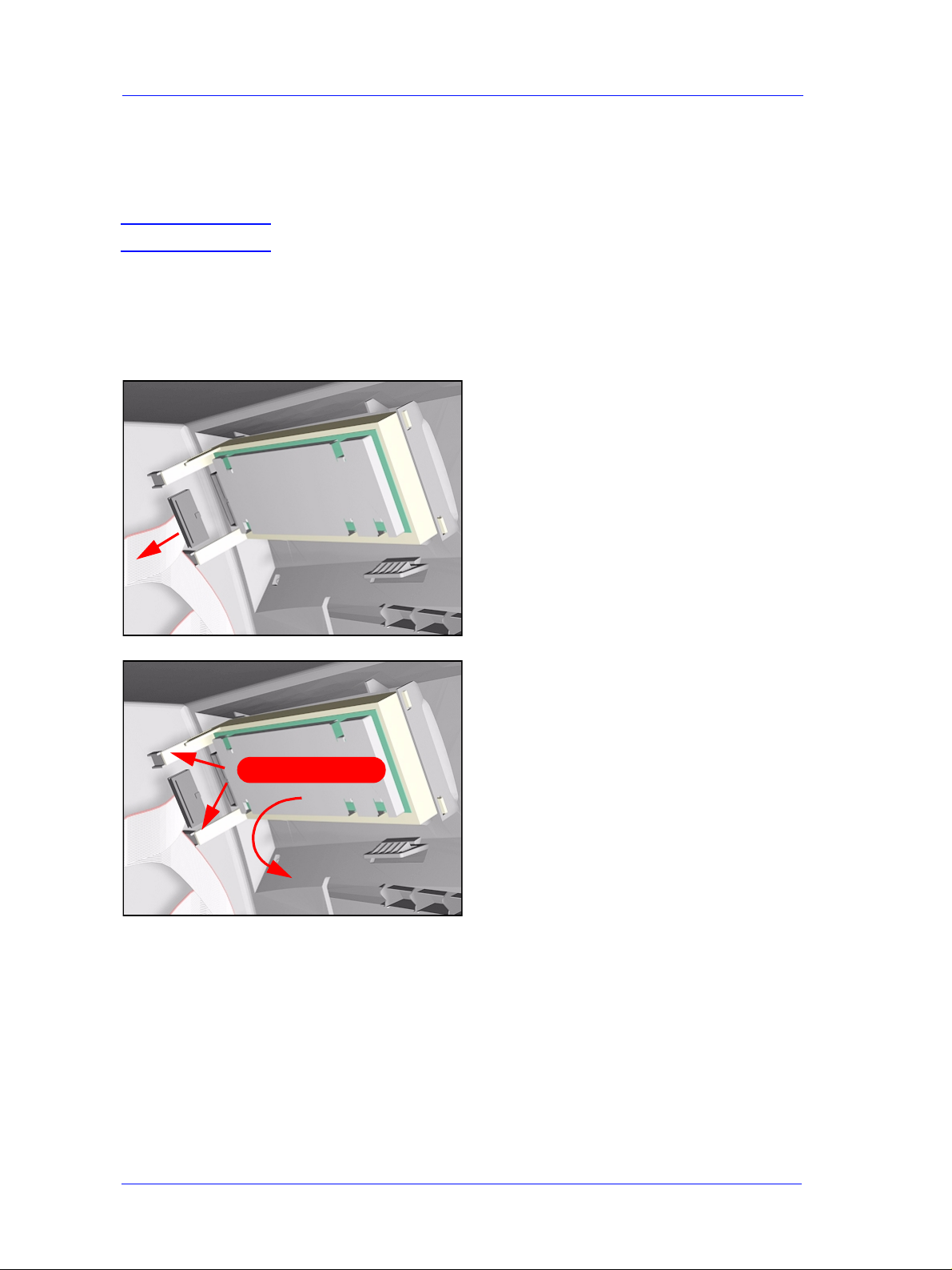
1. When installing the new Line Sensor,
make sure you insert the Line Sensor
Cable through the correct hole (as
highlighted).
2. Install the Line Sensor by first
inserting the 2 locating pins and then
rotating upwards so that the clip locks
into place.
NOTE Make sure the Line Sensor is
clipped correctly and
securely, if not the Line
Sensor will malfunction.
3. Connect the Line Sensor Connector to
the Carriage PCA.
HP DesignJet 5000 and 5500 Series Printers Service Manual
8-55
Page 56

Removal and Installation
3XVKKHUH
4. Install the Carriage Cover.
NOTE Make sure the cover is
installed vertically, if not the
Cover Retaining Pins can be
broken.
5. Clip the Carriage Cover on both sides
of the Carriage Assembly by pushing
the clip downwards (with force if
necessary).
NOTE Make sure the clips are
locked correctly, if not the
Carriage Cover could
become loose and cause
major damage to the printer.
NOTE You must perform the
following Calibration when
the Line Sensor is replaced:
n Scan Axis Calibration ⇒ Page 5-7.
8-56
HP DesignJet 5000 and 5500 Series Printers Service Manual
Page 57

Removal and Installation
Scan-Axis Motor
Removal
WARNING Switch off the Printer and remove the Power Cord.
NOTE Refer to the table on Page 8-4 for information on screw types.
1. Remove the Right Rear Cover - Refer
to Page 8-16.
2. Remove the Left Hand Cover - Refer
to Page 8-6.
3. Remove the Right Hand Cover - Refer
to Page 8-10.
4. Remove the 5.5 mm nut from the left
hand side of the Printer that attaches
the Encoder Strip to the Spring Clip.
TIP The next step is performed
5. Release the Encoder strip from the
1. Apply Pressure
2. Release Encoder Strip
HP DesignJet 5000 and 5500 Series Printers Service Manual
by putting pressure on the
Spring Clip as shown.
Spring Clip.
8-57
Page 58

Removal and Installation
Tighten screw
6. Using a screwdriver, fully tighten the
Spring Release Screw to release the
tension on the Belt.
7. Disconnect the Scan-Axis Motor
Cable from position P23 on the Main
PCA.
P23
8. Unclip the Scan-Axis Motor Cable
from underneath the Service Station.
8-58
HP DesignJet 5000 and 5500 Series Printers Service Manual
Page 59

Removal and Installation
9. From the right-hand side, lift the
Tensioner Belt off the Scan-Axis
Motor.
10. While supporting the Scan-Axis
Motor, remove 2 T-15 screws (Type
B).
11. Lower the Scan-Axis Motor and
remove from the Printer.
Installation of the Scan-Axis Motor
NOTE Before installation, clean and oil the Slider Rods using the User’s
Slider Rods Lubrification Kit (Refer to Page 9-8).
WARNING When installing the Enco der Strip, make sure it is in serted in the
Encoder Sensor on the rear of the Carriage Assembly.
Note: When installing the Belt,
make sure that it is not twisted.
Insert Encoder Strip
Encoder Sensor
HP DesignJet 5000 and 5500 Series Printers Service Manual
8-59
Page 60

Removal and Installation
Cutter Assembly
Removal
WARNING Switch off the Printer and remove the Power Cord.
NOTE Refer to the table on Page 8-4 for information on screw types.
1. Open the Top Cover.
2. Pull the Carriage out along the Printer
to the position shown.
3. Lift up the Carriage Cover and
remove ALL the Printheads and close
the Carriage Cover.
8-60
HP DesignJet 5000 and 5500 Series Printers Service Manual
Page 61

Removal and Installation
4. Slide the Carriage to the position
shown.
5. Push in the 2 retaining clips either side
of the Printhead Tube Connector.
6. Pull the Printhead Tube Connector
towards you.
HP DesignJet 5000 and 5500 Series Printers Service Manual
8-61
Page 62

Removal and Installation
7. Push the button to release the
Printhead Tubes from the Carriage.
8. Release the retaining clip by pulling it
away from the holding brackets.
9. Remove 1 T-8 screw (Type V) and
washer that attaches the Cutter to the
Carriage.
8-62
HP DesignJet 5000 and 5500 Series Printers Service Manual
Page 63

Removal and Installation
10. Slide the Cutter towards you and
remove from the Printer.
HP DesignJet 5000 and 5500 Series Printers Service Manual
8-63
Page 64

Removal and Installation
Ink Supply St ation (ISS)
Removal
WARNING Switch off the Printer and remove the Power Cord.
1. Remove the Left Hand Cover - Refer
to Page 8-6.
2. Remove the Left Rear Cover - Refer
to Page 8-15.
3. Remove the Back Extension Cover
(Only for the 60" Model) - Refer to
Page 8-17.
4. Disconnect APS Cables (P5, P4 and
P3) from the ISS PCA.
P5
P4
P3
Press here
5. T o remove the ISS, stand at the end of
the Printer and press in the retaining
clip on the ISS.
8-64
HP DesignJet 5000 and 5500 Series Printers Service Manual
Page 65

Removal and Installation
INSIDE VIEW FRONT
6. While pressing in the retaining clip
(step 5), rotate the right side of the ISS
up and left.
7. Pull out the right side of the ISS.
8. Slide the ISS to the left and pull out
2
the left side to remove from the
Printer.
INSIDE VIEW REAR
1
1
HP DesignJet 5000 and 5500 Series Printers Service Manual
8-65
Page 66

Removal and Installation
Installation of ISS
NOTE If the ISS is to be replaced, make sur e you remove the APS from
the old ISS and, after installing the Grounding Plate, reinstall it
on the new ISS.
WARNING When replacing the ISS re member to insert the Ground ing Plate
into the slot as shown (before reinstalling the APS).
8-66
HP DesignJet 5000 and 5500 Series Printers Service Manual
Page 67

Removal and Installation
Air Pressurization System (APS)
Removal
WARNING Switch off the Printer and remove the Power Cord.
1. Remove the Left Hand Cover - Refer
to Page 8-6.
2. Remove the Left Rear Cover - Refer
to Page 8-15.
3. Remove the Back Extension Cover
(Only for the 60" Model) - Refer to
Page 8-17.
4. Remove the ISS - Refer to Page 8-64.
5. Remove the cables and tube from the
slot on the ISS.
n For the 42" Model, open the Cable
Clip under the ISS holding the APS
Cables to the ISS.
NOTE When removing the APS
from the ISS, take care with
the tube and cabl es attached
to the ISS.
6. Push the retaining clips on the left side
of the APS to release it from the ISS.
HP DesignJet 5000 and 5500 Series Printers Service Manual
8-67
Page 68

Removal and Installation
Installation of APS
WARNING When Installing the Air Pressurization System make sure the
tube and wires are placed in the dedicated slots and perform the
following steps:
1. Before installing the APS on the ISS,
insert first the 3 cables and then the
tube in the dedicated slot.
2. Install the APS on the ISS.
3. For the 42" Model, secure the APS
Cables to the ISS using the Cable Clip
under the ISS.
NOTE Before installing the ISS on
the Printer, make sure the
cable and tube are inserted in
the ISS slot.
8-68
HP DesignJet 5000 and 5500 Series Printers Service Manual
Page 69

Removal and Installation
Service St at ion Assembly
Removal
WARNING Switch off the Printer and remove the Power Cord.
NOTE Refer to the table on Page 8-4 for information on screw types.
1. Remove the Right Rear Cover - Refer
to Page 8-16.
2. Remove the Right Hand Cover - Refer
to Page 8-10.
3. Remove the Printhead Cleaners.
4. Manually slide the Carriage out of
the Service Station.
HP DesignJet 5000 and 5500 Series Printers Service Manual
8-69
Page 70

Removal and Installation
5. Disconnect the Service Station Cable
from the Main PCA (P15).
P15
6. Unclip the Scan-Axis Motor Cable
from the Service Station.
NOTE Follow the instructions in
step 7 carefully; LOOSEN
the screw and DO NOT
remove.
7. Loosen the T-20 screw (Type A)
securing the Service Station to the
side plate.
8-70
HP DesignJet 5000 and 5500 Series Printers Service Manual
Page 71

Removal and Installation
8. Remove 2 T-15 screws (Type F)
between the two slider rods that attach
the Service Station to the Chassis.
9. Standing in front of the Service
Station, lift it off the loosened screw.
10. Pull the assembly out towards you and
remove from the Printer.
NOTE Perform the following
Service Calibration if the
Service Station Assembly is
replaced:
n Service Station ⇒ Page 5-11.
HP DesignJet 5000 and 5500 Series Printers Service Manual
8-71
Page 72

Removal and Installation
Drop Detector Assembly
Removal
WARNING Switch off the Printer and remove the Power Cord.
1. Remove the Right Rear Cover - Refer
to Page 8-16.
2. Remove the Right Hand Cover - Refer
to Page 8-10.
3. Remove the Service Station Asse mbly
- Refer to Page 8-69.
4. Disconnect the Drop Detector cable
from the Service Station Cable.
Press clip to disconnect
5. Release the cable from the Service
Station.
8-72
HP DesignJet 5000 and 5500 Series Printers Service Manual
Page 73

Removal and Installation
6. Remove the T-15 screw (Type F) that
attaches the Drop Detector Assembly
to the Service Station.
7. Remove the Drop Detector from the
Service Station.
NOTE Move the Drop Detector
1
2
towards the front of the
Service Station until the
locating pin reaches the end.
Pin
8. Lift the Foam from the Service
Station.
NOTE The Foam may be full of ink
so be careful when ha ndling
it.
NOTE If you replace the Drop
Detector you must perform
the following Service
Calibration:
n Service Station ⇒ Page 5-11.
HP DesignJet 5000 and 5500 Series Printers Service Manual
8-73
Page 74

Removal and Installation
Hard Disk Drive (HDD)
Removal
WARNING Switch off the Printer and remove the Power Cord.
NOTE Refer to the table on Page 8-4 for information on screw types.
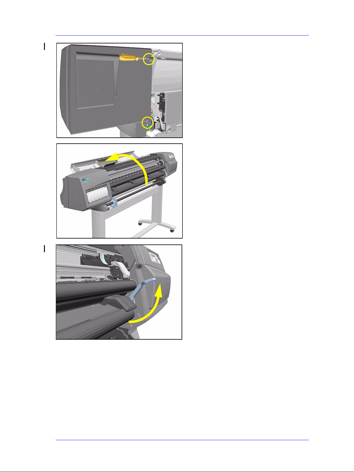
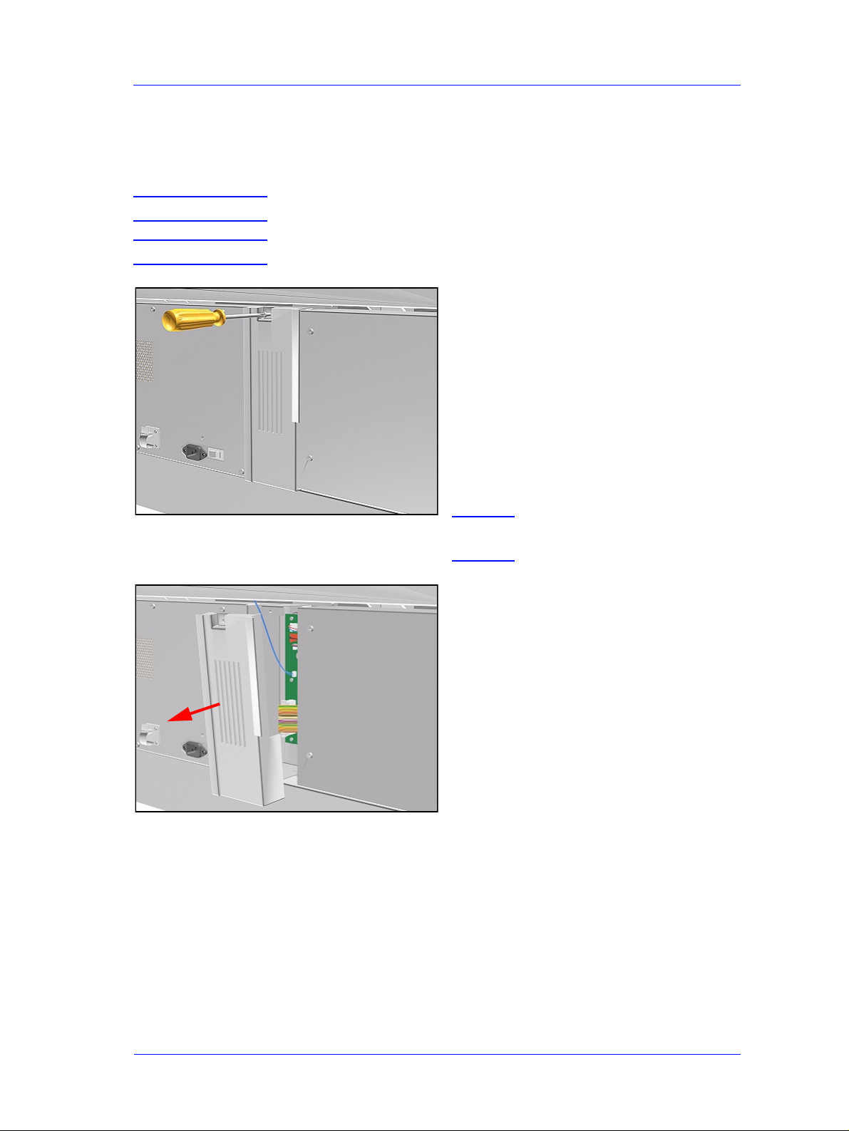
1. Remove 6 T -15 screws (Type B) from
the HDD Access Cover. Remove the
HDD Access Cover.
2.
Remove the HDD with its foam holder.
3. Disconnect the HDD Cable and Power
Supply Cable from the HDD.
8-74
HP DesignJet 5000 and 5500 Series Printers Service Manual
Page 75

Removal and Installation
Installation of Hard Disk Drive
NOTE If you replace the Main PCA and the HDD at the same time you
must perform ALL Service Calibrations (⇒ Page 5-3) and the
EEROM Setup Service Utility (⇒ Page 4-23).
WARNING When Installing the Hard Disk Drive make sure the holder is
placed in the right position so that it cannot move.
NOTE When the Hard D isk D r ive is
replaced perform the
following Service Utility:
n Backup EEROM (select HDD
replaced) ⇒ Page 4-30.
NOTE
If you have to replace the HDD Cable, refer to the following
drawing:
6KRUW&RQQHFWRUFRQQHFWV
WRWKH3&,WR,'(3&$
/RRSHG(QGFRQQHFWVWR
WKH+DUG'LVN'ULYH
,)7+(+''&$%/(,6127&211(&7('&255(&7/<,70$<
&$86(620(,17(50,77(17352%/(06
HP DesignJet 5000 and 5500 Series Printers Service Manual
8-75
Page 76

Removal and Installation
LAN Card
Removal
WARNING Switch off the Printer and remove the Power Cord.
1. Disconnect the LAN cable from the
LAN Card at the rear of the Printer.
2. Using a flat end screwdriver, unscrew
the two screws that attach the LAN
Card to the Printer.
3. Remove the LAN Card and store in a
safe place.
8-76
HP DesignJet 5000 and 5500 Series Printers Service Manual
Page 77

Removal and Installation
Memory and BootROM DIMM’s
Removal
WARNING Switch off the Printer and remove the Power Cord.
NOTE Refer to the table on Page 8-4 for information on screw types.
1. Remove 4 T-10 screws (Type P) from
the DIMM Access Cover. Remove the
DIMM Access Cover.
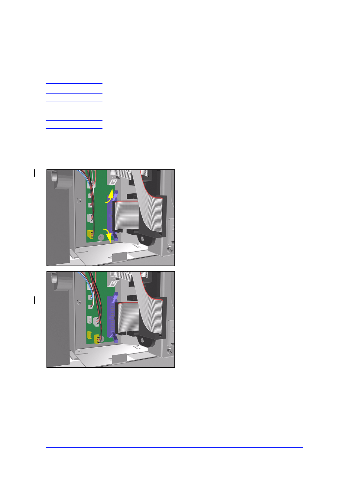
2. To remove a DIMM, first push down
2
1
the lower locking tab and then push up
the upper locking tab to release the
DIMM.
HP DesignJet 5000 and 5500 Series Printers Service Manual
8-77
Page 78

Removal and Installation
3. Pull out the DIMM. Take care that it
does not fall out.
Installation of DIMM’s
WARNING When installing the DIMM’s make sure they are in the correct
position as shown in the diagram.
NOTE Note the position of the BootROM and the SDRAM (memory)
modules.
J6 - Boot ROM
J7 - SDRAM
J8 - SDRAM
8-78
HP DesignJet 5000 and 5500 Series Printers Service Manual
Page 79

Removal and Installation
Electronics Module Cover
Removal
WARNING Switch off the Printer and remove the Power Cord.
NOTE Refer to the table on Page 8-4 for information on screw types.
1. Remove the LAN Card - Refer to
Page 8-76.
2. Remove Left Rear Cover - Refer to
Page 8-15.
3. Remove Right Rear Cover - Refer to
Page 8-16.
4. If present, remove the Ferrites from
the Ferrite Holder on the right side.
Push clip to release Ferrite (if present)
5. Remove 15 T-15 screws (Type B)
from the Electronics Module Cover.
HP DesignJet 5000 and 5500 Series Printers Service Manual
8-79
Page 80

Removal and Installation
Lift clips
NOTE Lift the Parallel Port Clips
before removing the Cover.
6. Remove the Electronics Module
Cover.
Installation of the Electronics Module Cover
NOTE When Installing the Electronics Module Cover make sure the
parallel port connector clips are in closed position i.e. UP, so that
they pass through the slot in the Cover.
Lift clips
8-80
HP DesignJet 5000 and 5500 Series Printers Service Manual
Page 81

Removal and Installation
Main PCA
WARNING This assembly does NOT include the PCI-to-IDE PCA (the small
PCA that connects the Main PCA to the Hard Disk Drive) as it
used to in the past. When installing the new Main PCA, mak e
sure that you reuse the PCI-to-IDE PCA that was disassembled
previously.
3&,WR,'(3&$
WARNING If you are working with an hp designjet 5000 (C6090A/V/I,
C6091A/V, C6095A/V/I, C6096A/V) and the new Main PCA has
the following connectors, you do NOT need to use them (they can
be ignored):
127QHHGHG
3
3+HDWHU
127QHHGHG
HP DesignJet 5000 and 5500 Series Printers Service Manual
21/<RQKSGHVLJQMHW
8-81
Page 82

Removal and Installation
Removal
WARNING Switch off the Printer and remove the Power Cord.
NOTE Refer to the table on Page 8-4 for information on screw types.
1. Remove the LAN Card - Refer to
Page 8-76.
2. Remove the Left Rear Cover - Refer
to Page 8-15.
3. Remove the Right Rear Cover - Refer
to Page 8-16.
4. Remove the Electronics Module
Cover - Refer to Page 8-79.
5. Disconnect and remove the Hard Disk
Drive for safety reasons - Refer to
Page 8-74.
6. Remove ALL Firmware/Memory
DIMMs - Refer to Page 8-77.
NOTE 0DNHVXUH\RX UHLQVWDOO WKH
)LUPZDUH0HPRU\ ',00V
RQWKHQHZ0DLQ3&$
7. Disconnect ALL Cables from the
Electronics Module.
8. Remove 2 T-10 screws (Type K) to
remove the PCI-to-IDE PCA.
8-82
HP DesignJet 5000 and 5500 Series Printers Service Manual
Page 83

Removal and Installation
9. Disconnect the PCI-to-IDE PCA and
remove from the Printer.
NOTE Make sure you reuse the
PCI-to-IDE PCA when
reassembling.
10. Remove 6 T -10 screws (Type K) from
the Main PCA.
11. Loosen 2 T-10 screws on the Main
PCA.
HP DesignJet 5000 and 5500 Series Printers Service Manual
8-83
Page 84

Removal and Installation
12. Remove by sliding the Main PCA to
the left and lifting out (see detail
below).
NOTE Detail of Main PCA removal.
Installation of Main PCA
NOTE When the Main PCA has been replaced, perform the Backup
EEROM ⇒ Page 4-30.
NOTE If you replace the Main PCA and the HDD at the same time you
must perform ALL Service Calibrations (⇒ Page 5-3) and the
EEROM Setup Service Utility (⇒ Page 4-23).
NOTE If you are not sure how the cables are connected on th e Main
PCA, each connector is labelled with the name of the assembly to
which it is connected.
NOTE
When installing the Hard Disk Drive, please refer to the instructions
for the instal la tio n of th e P CI- to -ID E PC A ( R efe r to P ag e
the installation of the HDD Cable (Refer to Page
8-87
8-86
) and
).
8-84
HP DesignJet 5000 and 5500 Series Printers Service Manual
Page 85

Removal and Installation
PCI-to-IDE PCA
Removal
WARNING Switch off the Printer and remove the Power Cord.
NOTE Refer to the table on Page 8-4 for information on screw types.
1. Remove the LAN Card - Refer to
Page 8-76.
2. Remove the Left Rear Cover - Refer
to Page 8-15.
3. Remove the Right Rear Cover - Refer
to Page 8-16.
4. Remove the Electronics Module
Cover - Refer to Page 8-79.
5. Disconnect and remove the HDD for
safety reasons - Refer to Page 8-74.
6. Remove 2 T-10 screws that secure the
PCI-to-IDE PCA.
7. Disconnect the PCI-to-IDE PCA and
remove from the Printer.
HP DesignJet 5000 and 5500 Series Printers Service Manual
8-85
Page 86

Removal and Installation
Installation of the PCI-to-IDE PCA
NOTE When installing the new PCI-to-IDE PCA, CONNECT THE
HDD POWER CABLE TO THE P36 CONNECTOR (IF
PRESENT) ON THE PCI-TO-IDE PCA AND NOT TO THE
P11 CONNECTOR ON THE MAIN PCA (even if the P11
connector is present and the HDD Power Cable was connected
there previously).
2.
3&RQQHFWRU
12
3&RQQHFWRU
'212786(
7+,6&211(&725
,)7+(3
&211(&725,6
35(6(17217+(
3&,WR,'(3&$
8-86
HP DesignJet 5000 and 5500 Series Printers Service Manual
Page 87

Removal and Installation
Installing the HDD Cable
When installing the HDD Cable between the HDD and the PCI-to-IDE PCA, make sure
you connect the correct ends as follows:
/RRSHG(QGFRQQHFWVWR
6KRUW&RQQHFWRUFRQQHFWV
WKH+DUG'LVN'ULYH
WRWKH3&,WR,'(3&$
,)7+(+''&$%/(,6127&211(&7('&255(&7/<,70$<
&$86(620(,17(50,77(17352%/(06
HP DesignJet 5000 and 5500 Series Printers Service Manual
8-87
Page 88

Removal and Installation
Power Supply Unit (PSU)
Removal
WARNING Switch off the Printer and remove the Power Cord.
NOTE Refer to the table on Page 8-4 for information on screw types.
1. Remove the LAN Card - Refer to
Page 8-76.
2. Remove the Left Rear Cover - Refer
to Page 8-15.
3. Remove the Right Rear Cover - Refer
to Page 8-16.
4. Remove the Electronics Module
Cover - Refer to Page 8-79.
PCA PS Connector
5. Disconnect and remove the Hard Disk
Drive for safety reasons - Refer to
Page 8-74.
6. Disconnect the PCA Power Supply
connector from the Main PCA.
8-88
HP DesignJet 5000 and 5500 Series Printers Service Manual
Page 89

PS Fans
Removal and Installation
7. Remove the plastic protective cover
from the Power Supply Unit.
8. Disconnect ALL Cables from the PSU
(see Installation of PSU for
connections).
Press
PS Switch
PS Socket
9. Remove 7 T-10 screws (Type K) and
remove the PSU.
HP DesignJet 5000 and 5500 Series Printers Service Manual
8-89
Page 90

Removal and Installation
Installation of the Power Supply Unit (PSU)
WARNING After installing the Power Supply Unit, remember to place the
plastic protective cover over the unit.
NOTE The Power Supply Unit connections are illustrated below.
PS Fans
PS Socket
PS Switch
8-90
HP DesignJet 5000 and 5500 Series Printers Service Manual
Page 91

Removal and Installation
Ink Supply St ation (ISS) PCA
Removal
WARNING Switch off the Printer and remove the Power Cord.
NOTE Refer to the table on Page 8-4 for information on screw types.
1. Remove the LAN Card - Refer to
Page 8-76.
2. Remove the Left Rear Cover - Refer
to Page 8-15
3. Remove the Right Rear Cover - Refer
to Page 8-16.
4. Remove the Electronics Module
Cover - Refer to Page 8-79.
5. Disconnect ALL Cables from the ISS
PCA (see installation of ISS PCA for
connections).
6. Remove 5 T -10 screws (Type K) from
the ISS PCA.
7. Remove the ISS PCA.
HP DesignJet 5000 and 5500 Series Printers Service Manual
8-91
Page 92

Removal and Installation
Installation of the ISS PCA
NOTE The ISS PCA connections are illustrated below.
P5
P6
P4
J3
P3
P2
J1
J Position
J1
J3
Connection Connector
Color
ISS Cable white
Main PCA white
P Position
P2*
P3
P4
P5**
P6**
Connection Connector
Color
Ink Leak Detector white
APS Temperature white
APS Valve red
APS Pump white
APS Pump (Spare) white
* The Ink LeakDetector has been discontinued so this connector is no longer used.
** There are 2 connectors available for the APS Pump and any one of them can be used.
8-92
HP DesignJet 5000 and 5500 Series Printers Service Manual
Page 93

Removal and Installation
Ink Leak Detector - If Present (Only Applicable to the 5000 Series)
Removal
WARNING Switch off the Printer and remove the Power Cord.
NOTE Refer to the table on Page 8-4 for information on screw types.
1. Remove the Left Rear Cover - Refer
to Page 8-15.
2. Remove the Top Cover - Refer to
Page 8-5.
3. Remove the Back Cover - Refer to
Page 8-23.
P2
4. Disconnect the Ink Leak Detector
cable at position P2 from the ISS
PCA.
5. Remove one T-15 screw (Type B) to
release the cable clip on the Top EMC
cover.
HP DesignJet 5000 and 5500 Series Printers Service Manual
8-93
Page 94

Removal and Installation
6. Press the retaining clip on the Ink
Leak Detector and release it.
TIP A screwdriver can be used to
press the retaining clip down.
7. Remove the Ink Leak Detector from
the Printer.
8-94
HP DesignJet 5000 and 5500 Series Printers Service Manual
Page 95

Removal and Installation
Cooling Fans
Removal
WARNING Switch off the Printer and remove the Power Cord.
NOTE Refer to the table on Page 8-4 for information on screw types.
1. Remove the LAN Card - Refer to
Page 8-76.
2. Remove the Left Rear Cover - Refer
to Page 8-15.
3. Remove the Right Rear Cover - Refer
to Page 8-16.
4. Remove the Electronics Module
Cover - Refer to Page 8-79.
5. Disconnect and remove the Hard Disk
Drive for safety reasons - Refer to
Page 8-74.
6. Remove 2 screws for each Cooling
Fan from underneath the Electronics
Module.
HP DesignJet 5000 and 5500 Series Printers Service Manual
8-95
Page 96

Removal and Installation
7. Remove the plastic Protective Cover
from the Power Supply Unit.
8. Disconnect the Cooling Fan Cables
from the Power Supply Unit.
9. Remove the Cooling Fans from the
Printer.
8-96
HP DesignJet 5000 and 5500 Series Printers Service Manual
Page 97

Removal and Installation
LEFT
Electronics Module (as one complete Assembly)
Removal
WARNING Switch off the Printer and remove the Power Cord.
NOTE Refer to the table on Page 8-4 for information on screw types.
1. Remove the Left Rear Cover - Refer
to Page 8-15.
2. Remove the Right Rear Cover - Refer
to Page 8-16.
3. Disconnect ALL Cables from the
Main PCA (Right Rear Cover) and
ISS PCA (Left Rear Cover) and
remove the Ferrites from the left side.
4. Remove 2 T -15 screws (Type B) from
the both sides of the Electronics
Module.
RIGHT
5. Lift the Electronics Module up (to
clear it from the shoulder screws) and
remove from the Printer.
1
2
1
HP DesignJet 5000 and 5500 Series Printers Service Manual
8-97
Page 98

Removal and Installation
Pinch-Wheels
Removal
WARNING Switch off the Printer and remove the Power Cord.
NOTE Refer to the table on Page 8-4 for information on screw types.
1. Remove the Top Cover - Refer to
Page 8-5.
2. Remove the Back Cover - Refer to
Page 8-23.
3. Remove the Electronics Module -
Refer to Page 8-97.
4. Remove EMC Covers as one
assembly - Refer to Page 8-32.
NOTE For the next steps place the
Media Lever in the UP
position.
5. Remove the following T-20 screws
(Type Q):
n For the 60" Model remove 4 screws
from each group of 4 Pinch-Wheels
(5 groups in total).
n For the 42" Model remove 4 screws
from each group of 4 Pinch-Wheels
(3 groups in total) and 2 screws
from the one group with 2 PinchWheels.
8-98
HP DesignJet 5000 and 5500 Series Printers Service Manual
Page 99

Removal and Installation
6. First remove lateral Pinch-Wheels
with their Coupling Plates.
NOTE For Pinch-Wheel groups
installed around the Mount
Brackets do the following:
REMOVE
COUPLING PLATES
7. From the front of the Printer, remove
the Coupling Plate corresponding to
the position of the Mount Bracket.
n 3 Mount Brackets in the 60" Model.
n 1 Mount Bracket in the 42" Model.
8. From the rear of the Printer, rotate the
group (90 degrees) and pull it through
R
O
T
A
1
T
E
0
9
0
the gap left by the Coupling Plate.
2
Installation of Pinch-Wheels
NOTE During installation, make sure you install the White Pinch-
Wheels at each end of the Printer axis.
HP DesignJet 5000 and 5500 Series Printers Service Manual
8-99
Page 100

Removal and Installation
Pinch-Wheel Cam
Removal
WARNING Switch off the Printer and remove the Power Cord.
NOTE Refer to the table on Page 8-4 for information on screw types.
1. Remove Right Rear Cover - Refer to
Page 8-16.
2. Remove Left Rear Cover - Refer to
Page 8-15.
3. Remove the Deflectors - Refer to Page
8-119.
4. Remove the Left Hand Cover - Refer
to Page 8-6.
5. Remove the Right Hand Cover - Refer
to Page 8-10.
6. Remove the Left Hand Trim - Refer to
Page 8-22.
7. Remove the Right Hand Trim - Refer
to Page 8-20.
8. Remove the Media Lever Assembly Refer to Page 8-18.
9. Remove the ISS - Refer to Page 8-64.
10. Remove the Service Station - Refer to
Page 8-69.
11. Remove the Vacuum Fan - Refer to
Page 8-103.
12. Remove the Electronics Module Refer to Page 8-97.
13. Remove the Booster Fan - Refer to
Page 8-108.
8-100
14. Remove the Media Sensor - Refer to
Page 8-109.
15. Remove the Entry Roller - Refer to
Page 8-111.
HP DesignJet 5000 and 5500 Series Printers Service Manual
 Loading...