

Page 1
Setup Instructions
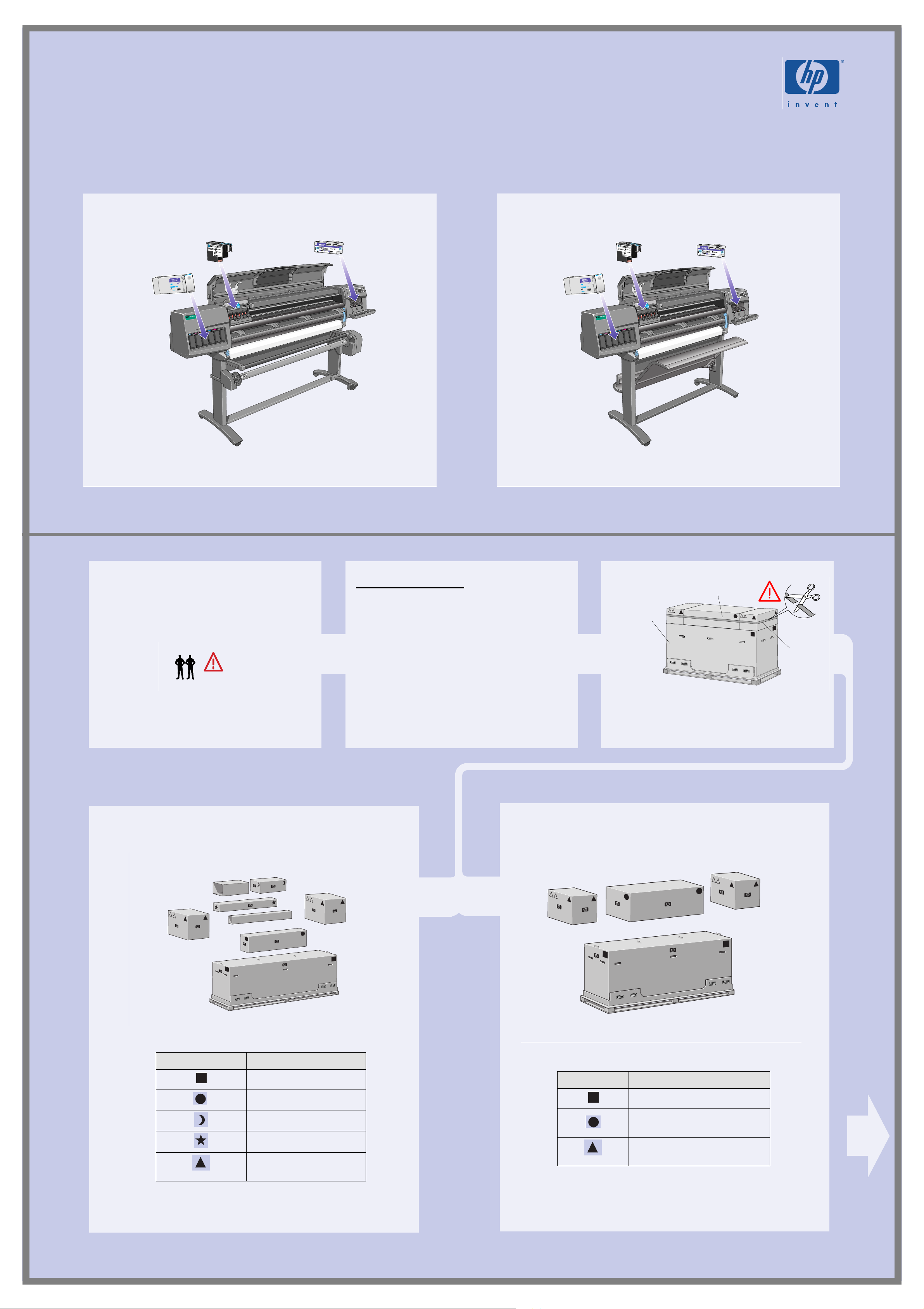
HP DesignJet 5000PS & HP DesignJet 5000
HP DesignJet Printer
60 inch (1.57 m)
Read these instructions carefully...
What You Will Need For This Procedure:
n Because some of the components of the printer are
bulky, you may need two or three people to lift
them. When this is necessary this symbol is
displayed:
st570
st501
The Take-Up Reel
If you are installing ONLY the
Take-Up Reel, go directly to page 3,
Step 5.
HP DesignJet Printer
42 inch (1.07 m)
Accessory boxes
Main printer
box
st506a
st501a
Strap
M4
n The time required to assemble the printer is about
two hours, depending on the printer model.
1. Preliminary unpacking
HP DesignJet 60 inch (1.57m)
Cut the strap from around the Accessory boxes
carefully, as the boxes may fall as soon as the strap
is cut.
HP DesignJet 42 inch (1.07m)
The shapes on the boxes identify the contents, refer to the table below:
Mark on box Content of box
Printer body
Legs Assembly
Take-Up Reel
Take-Up Reel Tubes
Assorted consumables
and documents
st573
st572
The shapes on the boxes identify the contents, refer to the table below.
Mark on box Content of box
Printer body
Legs Assembly and Bin
Assembly
Assorted consumables and
documents
Page 1
Page 2
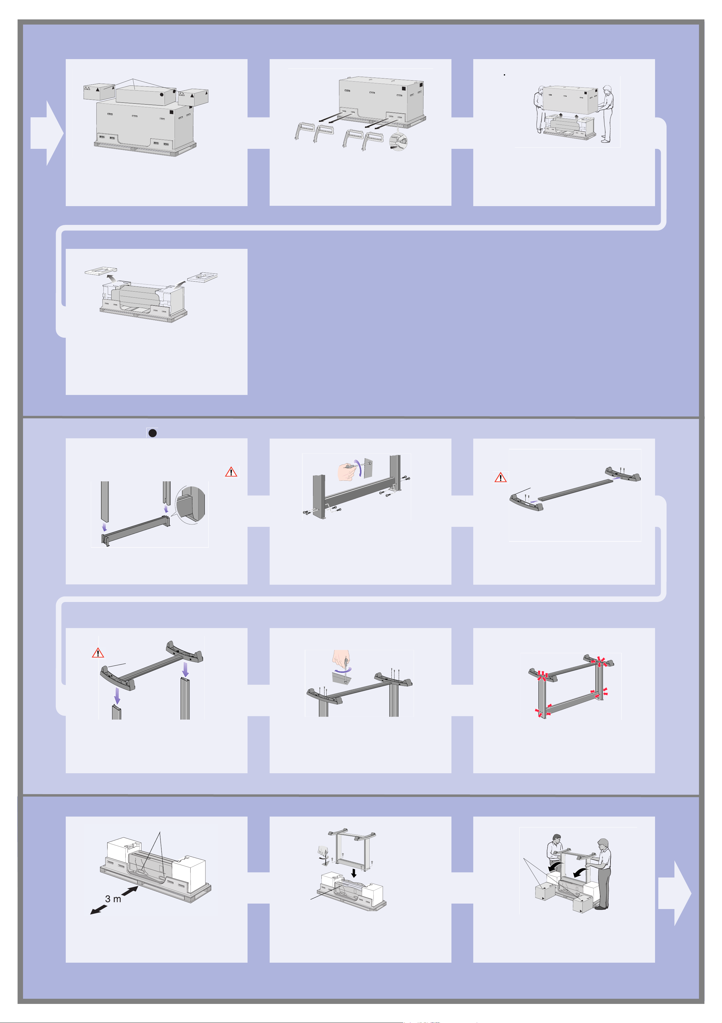
Accessory Boxes
M4
st506
Remove the boxes from the top of the main printer
box.
st507
Remove all eight plastic handles from both sides
of the box.
st508
Remove the main printer box.
Remove the two Packing Pieces.
2. Legs Assembly
When you are unpacking the legs assembly, you
will see that there is ANTI-SLIP material around
the wheels of the feet. DO NOT REMOVE this
material yet.
st509
Do NOT remove
anti-slip material
st511
Attach the Legs to the outside of the Cross Brace.
Do NOT remove
anti-slip material
st512
st513
Install eight screws into the Legs as shown above.
Screw the Feet into the Cross Brace.
st514
Position the Feet onto the Leg Assembly.
3. Installing the legs onto the printer
Printer Handles
Secure the feet to the Legs with 6 screws.
st522a
st516
st515
Important: Some screws may have come loose
during assembly. Check that all screws are fully
tightened.
Orientate
the boxes
exactly as
shown here.
Page 2
st502
Find the handles on the rear of the printer as
shown. There must be three meters from this point
which is clear of obstructions.
Pull aside plastic
covering
Carefully pull aside the plastic covering and put
the legs assembly on the Printer as shown and
secure with four screws.
st523a
Remove the accessories from the accessory boxes.
Put the two boxes on the floor as shown and tilt the
printer onto the boxes. Note: The boxes must have
the polystyrene inside to support the weight of the
printer.
Page 3
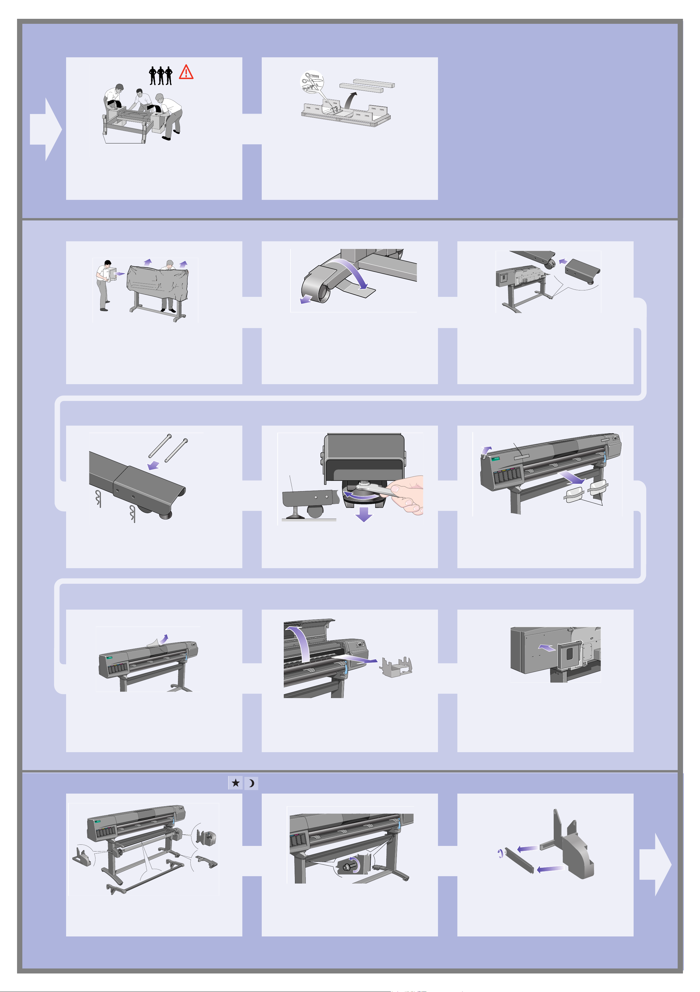
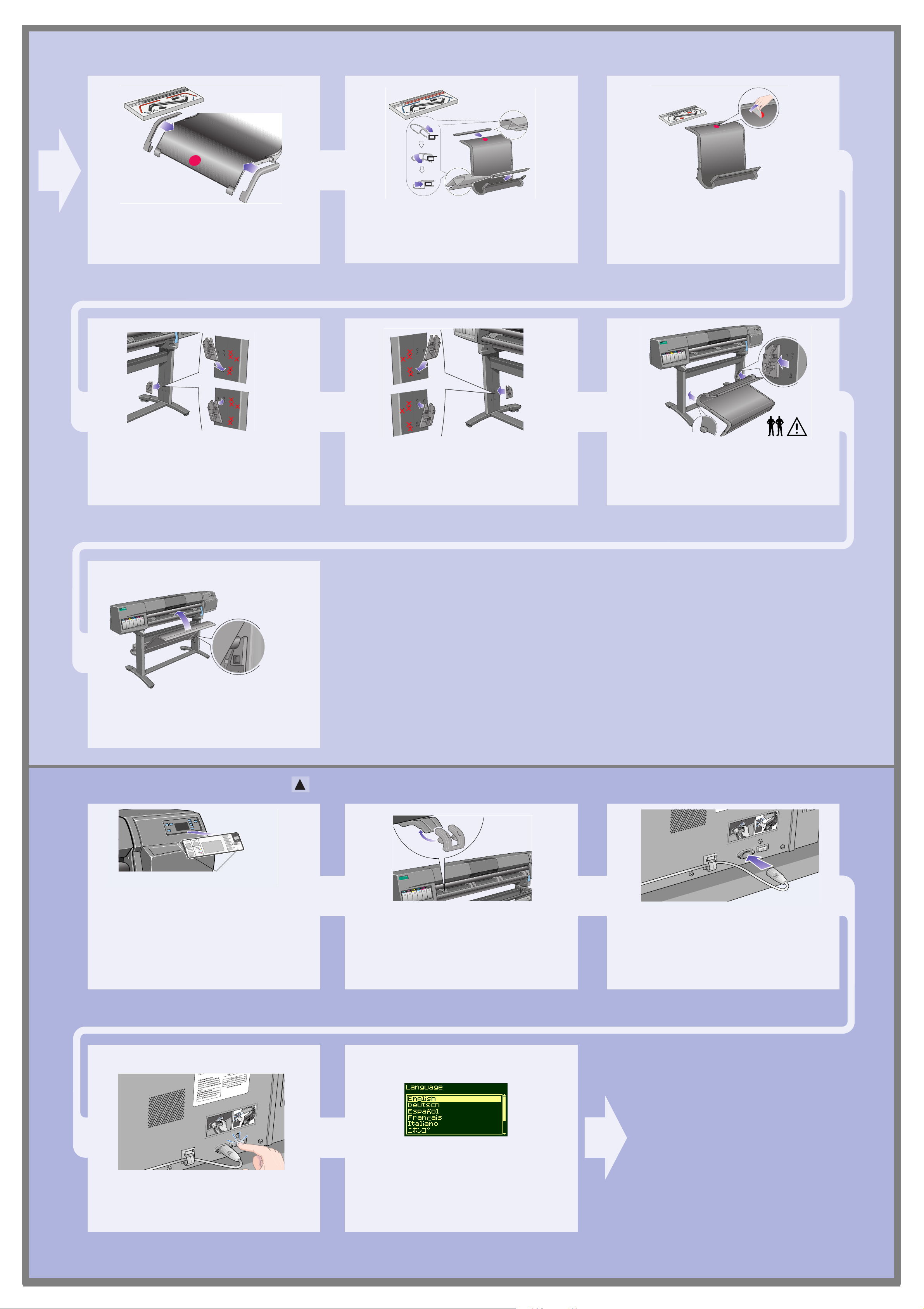
Anti-slip pads
Carefully lift printer into the upright position.
4. More unpacking
st524a
st521
Remove the media rolls and spindles from the
Shipping Container.
st525
Remove the End Packings and the plastic covering
from the printer.
st526
Tear off and discard the anti-slip material from the
wheels. Important: You do not need to lift the
printer.
Side view
st163
Install the two stabilizers onto the rear of the feet
as shown. Make sure you install both stabilizers
onto the rear of the feet.
Packing Strap
Install the pins into the two stabilizers and secure
with the retaining clips.
Adjust the stabilizer feet so that the wheels do not
touch the floor.
st527
Remove the Packing Tape and the Desiccant Bag.
Desiccant Bag
st528
Remove the protective covering from the Printer
Window.
5. Install the Take-Up Reel Assembly
st529
Open the window and remove the Carriage
Packing Material.
st569
Install the Pocket on the rear of the printer.
Install the Take-Up Reel as shown in the following
steps.
st530
st531
Loosen the four screws shown above.
Release the clamp on the left-hand assembly by
removing the screw.
Page 3
Page 4
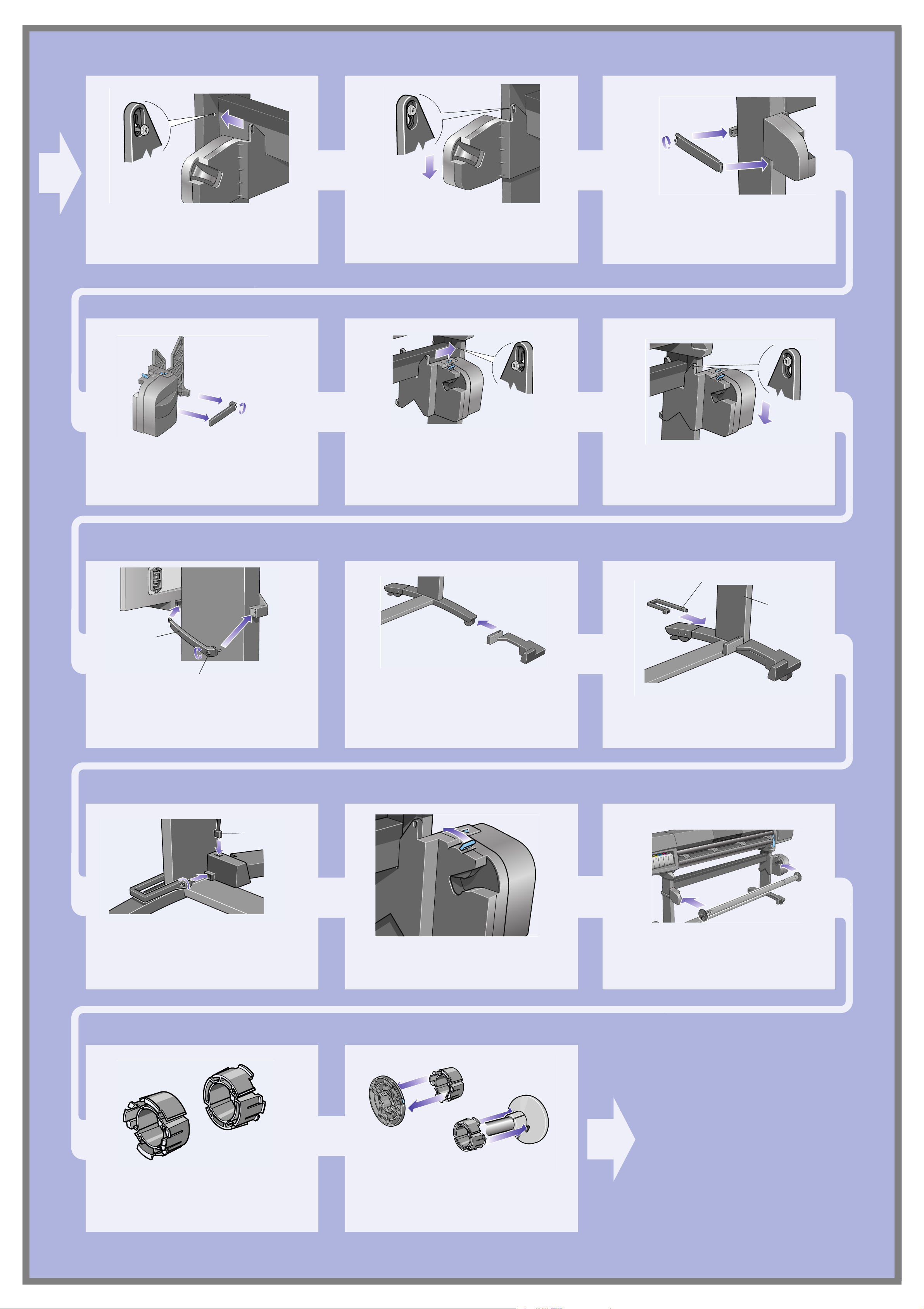
st532
st533 st534
Install the left-hand assembly on to the loosened
screws installed earlier.
st535
Release the clamp on the right-hand assembly by
removing the screw.
Pull the left-hand assembly down so that it rests
securely on the screws.
st536
Install the right-hand assembly on to the loosened
screws installed earlier.
Close the clamp and secure with the clamp screw
on to the leg.
st537
Pull the right-hand assembly down so that it rests
securely on the screws.
Clamp
st538
Clamp screw
Install the clamp and secure with the clamp screw
as shown above.
Important: Tighten all screws securing the TakeUp Reel on to the legs.
st539
Install the front of the sensor assembly onto the
front of the
right foot assembly as shown above.
Sensor clamp
Right
leg
st540
Slide the sensor clamp hard up against the leg and
then secure the sensor clamp with a screw.
Sensor Cable
st542
Tighten the screw to secure the clamp in place and
connect the sensor cable as shown above.
Ensure the spindle lock is open.
st545
st546
Install the Take-Up Reel spindle into the printer by
pushing firmly on each end of the spindle.
Page 4
3 inch core adaptors
st591
If you want to use a 3 inch (76mm) cardboard core
instead of the plastic core supplied, adaptors are
available with your printer.
st593
Install the adapters on to the media guides as
shown. Note: These are for use with a 3 inch
(76mm) cardboard core only.
Page 5

6. Install Deflectors (HP DesignJet 60 inch/1.52 m only)
Important note for owners of the
HP DesignJet 42 inch (1.07 m)
If your printer is an HP DesignJet 42 inch (1.07 m)
and you have ordered the Take-Up Reel as an
accessory, you should not install the deflectors.
The bin assembly, which is the next procedure,
contains a deflector integrated into its design.
Tabs facing
this way
st548
Deflector bar
st549
The deflector bar can be found inside the core
st547
Install the left and right deflectors on top of the
printer’s cross brace.
st550
Attach end caps to the bar and supports with the
two screws provided.
Slide deflector supports sideways until the T-piece
on top of the support is fully inserted into the gap
between the cross brace and the printer leg.
st543
Connect the power cord into the rear of the take-up
reel.
tubes, in the box. Rest the deflector bar on
the two supports.
Turn on the take-up reel by turning the switch to
On at the rear.
7. Bin Assembly installation (HP DesignJet 42 inch/1.07 m only)
Red
orientation
dot
Remove the bin ‘film’ from its container. Make
st579
Insert the four bars into the slots in the right bin
holder, and then mount the left bin holder on to the
four bars.
five creases in the film at the dimensions shown
above. Note the position of the red orientation dot
in relation to the creases.
1cm
1cm
7cm
1cm
1cm
st580
st581
Slide the bin ‘film’ into the grooves in the bin
holders. Insert the end with the two creases first.
Slide the film fully to the end, so that the creases
are in the correct positions.
st582
Secure the film in place with two clips at one end.
st583
st584
Attach caps onto the clips. Secure the film in place at the other end with two
more clips.
Page 5
Page 6
Attach caps onto the clips.
1
2
1
2
st585
st586
Install end pieces to the film and sides as shown
above.
st586a
Remove the red orientation dot.
st587
Install the right adapter to the right leg at the rear
as shown above. The right hand adapter is marked
with the letter ‘R’.
st588
Install the left hand adapter to the left leg at the
rear as shown above. The left hand adapter is
marked with the letter ‘L’.
st589
Insert the bin on to the adaptors horizontally and
insert the small pins into their slots.
st590
Raise the bin until the large pins align with their
slots and the bin drops into place.
8. Front Panel Label and Power On
Cutouts
st556
Attach the Front Panel Overlay to the Front Panel.
Ensure that the cutouts on the Overlay are
correctly positioned on the Front Panel locating
tabs.
Install the extensions onto the media deflectors.
st557
Plug the power cord into the socket next to the
power switch, and then into the AC power outlet.
Page 6
st558
Turn the power isolator switch at the rear of the
printer to the on position.
st557
Select the language you want for the front panel
using the up and down keys. Press Enter.
Page 7

9. Ink System Startup
INK STARTUP
Printer startup.
INK CART. ACCESS
HP ink cartridges
successfully installed
Press ENTER to
continue
The front panel displays the above. Press ENTER.
INK STARTUP
Initializing printer
Please wait xx sec
Colored label
at the top of the
Ink Cartridge
Slide all of the ink cartridges into their slots.
INK STARTUP
Lift window to
replace SETUP
printheads
st054
Press ENTER to continue
When all SIX ink cartridges have been installed
correctly, the front panel will display the above.
Carriage
Assembly
Press ENTER. The front panel displays the above.
Insert printheads
REPLACE (XX04)
REPLACE (XX04)
REPLACE (XX04)
REPLACE (XX04)
REPLACE (XX04)
REPLACE (XX04)
Printhead
When the printer has primed the ink system, the
front panel displays the above message.
st056a
Open the window and locate the printhead
carriage.
The front panel will display the above message.
st057
Pull up and release the latch on top of the Carriage
Assembly.
st092
Lift up the cover. This will now give you access to
the setup printheads.
st093
To remove the setup printhead, lift up the blue
handle.
Place your index finger through the loop of the
blue handle.
10. Installing the Printhead and Printhead Cleaner
st095
Pull the handle upwards until the setup printhead
is released from the Carriage Assembly.
Make sure that you remove and discard all six
setup printheads.
If the printer does not “BEEP” when you insert the
last printhead and “Reseat” is displayed on the
front panel, try re-seating the printhead more
firmly. If the problem persists, refer to the Using
Your Printer CD.
st062
Remove the blue protective cap and the clear
protective tape from the printhead’s nozzles.
st063
Push down in the direction indicated by the arrow
shown above. When all the printheads are inserted
correctly and accepted by the printer, the printer
will “BEEP”.
Page 7
Page 8

All printheads OK,
Close cover and
window to
continue
INK STARTUP
Open right door to
access printhead
cleaners
If all the printheads have been installed correctly,
the front panel displays the above.
Close the cover on the carriage and shut the
window.
The front panel displays the above.
st050
Open the printer’s right door below the front
panel.
st071
Insert each printhead cleaner into the correct color
slot location, as indicated by the arrow shown
above.
INK STARTUP
Checking printhead
CLEANERS
st072
When the printhead cleaner has been pushed all
the way in, press inwards and downwards as
indicated by the arrow shown above, until it clicks
into place.
st073
When you have inserted the all printhead cleaners
into the printhead service station, close the door.
The front panel displays the above.
11. Installing a roll
A
B
The printer will now start the printhead test.
If it is successful, the front panel will instruct you
to load the media; then the printer will run the
printhead alignment check.
st002
Remove the blue colored stop A from the left-hand
end of the spindle, and stand the spindle vertically,
with the fixed stop B on the floor.
B
st003
Slide the new roll of media on to the spindle.
Make sure the orientation of the paper is loaded
exactly as shown. The blue media guide must be
on the left.
st005
Put the removable stop onto the spindle and push it
on as far as it will go.
Page 8
A
st006
With the blue colored roll stop on the left, slide the
spindle into the printer as shown by the arrows A
and B. The paper should hang down from the roll
exactly as shown.
Page 9

12. Loading the media
1m (3ft)
st009a
Press the media load key in the front panel. The front panel displays the above. Using the up
and down keys, select the Roll option and press
Enter.
st009a
Open the window.
Lift the media load lever.
st009
The front panel displays the above.
st010
Pull out approximately 1 m (3 ft) of paper.
st011
Insert the edge of the roll of media above the black
roller.
st012
Continue inserting the roll of media until it
emerges from the printer as shown above
st104ab
Take hold of the edges of the media now extending
from the exit slot. Align the right side of the media
with the edges of the roll.
st014
When the paper is correctly aligned with the edges
of the roll, lower the media load lever.
st039a
Lower the window of the printer. If you have a Take-Up Reel installed, the front
panel will display the above. Using the up and
down keys, select ‘No’. For information on
loading the Take-Up Reel, refer to the Pocket
Guide or the User’s Reference Guide.
The front panel displays the above.
Select the vendor of the media you are using. In
this case it will probably be Hewlett-Packard. For
more information on this function, see the User’s
Reference Guide.
The front panel displays the above.
Using the up and down keys, select the type of
media you have loaded.
The front panel displays the above.
Using the up and down keys, select the length of
media you have loaded. The length will be on the
box which the media came in. If you’re not sure,
select ‘Not Known’.
Page 9
Page 10

The printer trims the edge of the media and
displays the above.
INK STARTUP
Printer startup
has finished.
Press ENTER to
continue
st015
Carefully wind the excess media back onto the
spindle. Use the blue removable media stop to turn
the roll of media in the direction shown above.
Press Enter.
If you are performing the printer setup for the first
time, the printer will now start the printhead
alignment routine. The front panel displays the
above.
When the printhead alignment has finished, the
front panel displays the above. Press Enter.
13. Hardware Setup
Printer
PC, Macintosh,
or workstation
Printer
Network Server
PC, Macintosh,
or workstation
Your printer can be connected to a computer
directly by a parallel cable or to a computer via a
network connection.
Direct Connect:
Go to the next page and perform the procedures
for installing the software.
st565a
If you are using a direct connection to the
computer, connect the parallel cable to the printer
as shown.
Network Connect
Go to the next page and perform the procedures
for setting up your printer on the network and
installing the software.
To obtain useful information before setting up
your printer on the network:
n Go to the Setup menu in the printer’s front panel.
n Select I/O Setup and press Enter.
n Select Card ID and press Enter.
st565
If you are using a network connection, connect a
network cable to the JetDirect Card at the rear of
the printer.
Write down the hardware and IP addresses:
(ETHER=xxxxxxxxxxxx and IP=nnn.nnn.nnn.nnn).
Macintosh users should also write down the
Appletalk name (AT =xxxx…).
For HP DesignJet WebAccess users:
To use the HP DesignJet WebAccess feature, you
will need to configure your printer on an IP
network. If you have a PC running Windows, use
the HP DesignJet Printers Software Setup CD (see
the next page). Otherwise see the JetDirect
Administrator’s Guide.
Page 10
Page 11

Page 11
Page 12
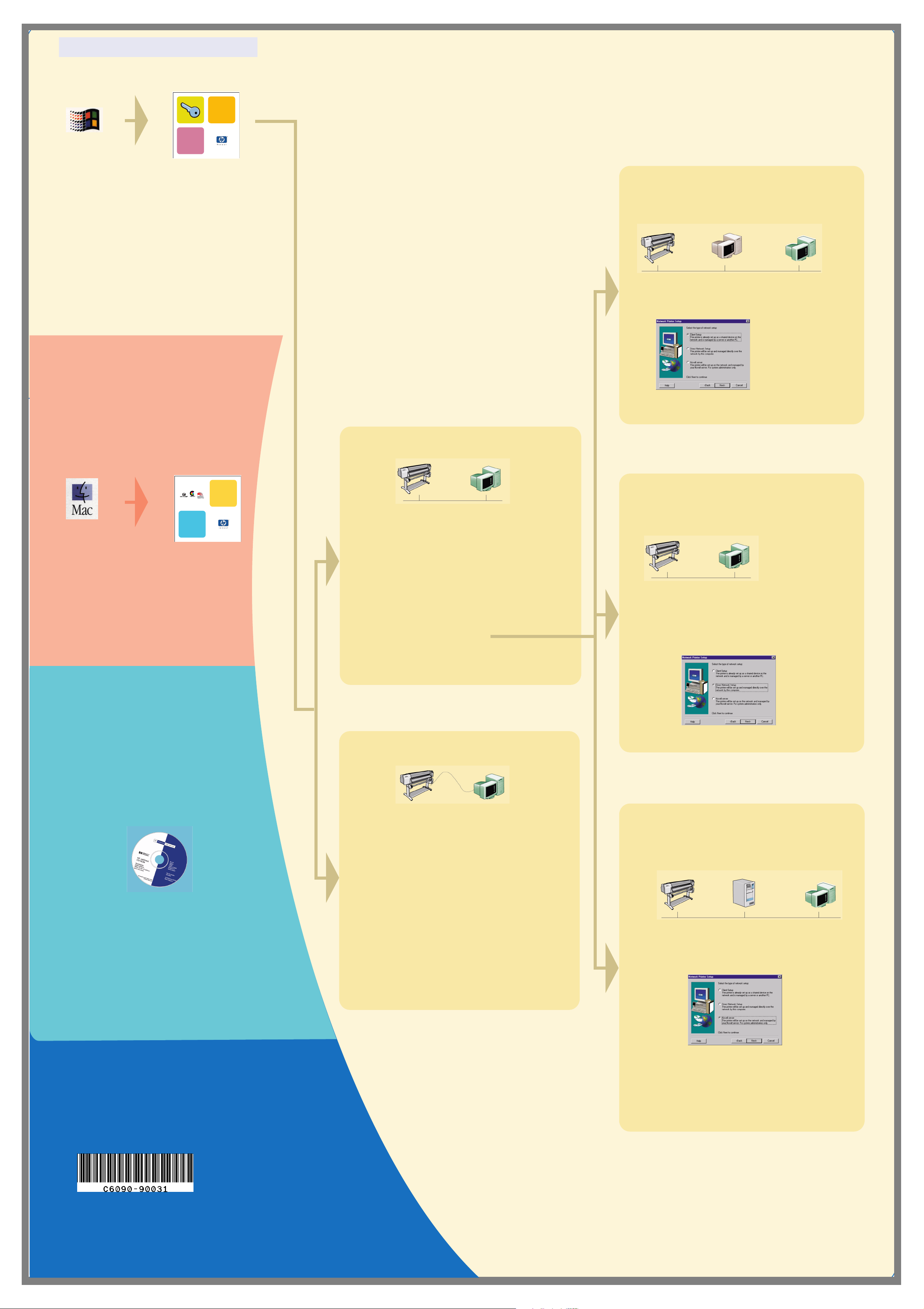
1. Set Up Your Software (all models)
Software setup
For Windows users
hp designjet printers
Macintosh software
hp designjet 5000
series
Fall 2000
Windows
Use this CD
How will this Printer
be connected to your
Computer?
Client Setup
The printer is already set up as a shared device
on the network and is managed by a server or
another PC.
Printer Printer Server Your PC
4. When you get to the Network Printer Setup
screen, select Client Setup.
Macintosh
(HP DesignJet 5000 Series
Use this CD
Macintosh Software)
Network Setup
Printer
Your PC
1. Connect the printer to the network.
2. Make sure the printer is properly set up,
turned on and ready to print.
3. Insert the HP DesignJet Printers Software
Setup CD and answer the questions.
(If the CD does not start automatically, run
the SETUP.EXE program in its root
directory).
Select the type of network setup
5. Follow the instructions to complete the
software setup.
Direct Network Setup
The printer will be set up and managed directly
over the network by this computer.
Printer
Your P C
4. When you get to the Network Printer Setup
screen, select Direct Network Setup.
UNIX
To install network software,
insert the HP Jetdirect CD.
Direct Connect (parallel cable)
Printer
Your PC
1. Make sure the printer is properly set up,
turned on and ready to print.
2. Make sure the printer is connected to your
computer via a parallel and that all the cable
connections are connected properly.
3. Insert the HP DesignJet Printers Software
Setup CD and answer the questions.
(If the CD does not start automatically, run
the SETUP.EXE program in its root
directory).
4. Follow the instructions to complete the
software setup.
Novell Server Setup
The printer will be set up on the network and
managed by your Novell server.
For system administrators only.
Printer Your PCNovell Server
4. When you get to the Network Printer Setup
screen, select Novell Server Setup.
If you have Internet access, you can also get the software from
HP’s Web Site, the HP Download Service, Compuserve or AOL. You
will find more through the driver software installation instructions, and
a description of all supported installation methods on our web site,
www.hp.com/go/designjet.
For detailed information about all CDs see the documentation supplied
with them. (There may be other CDs in the box with your printer. They
contain samples and additional material—use them later.)
Macintosh is a product
of Apple Computer Inc.
PostScript is a trademark
of Adobe Systems
Incorporated.
Unix is a registered trademark
Copyright Hewlett-Packard
Company 2000
Part Number: C6090-90031
First Edition Sep. 2000
Printed in Europe
Hewlett-Packard Company
Inkjet Commercial Division
Avda. Graells, 501
08190 Sant Cugat del Vallès
Barcelona, Spain
in the United States and other
countries licensed exclusively
through X/Open Company Ltd.
Windows is a registered trademark of
Microsoft Corporation.
5. Follow the instructions to complete the software
setup.
Don’t forget...
• Keep the packaging in which your printer was packed; there are repacking instructions on the HP
web-site, www.designjet-online.com, in case you need to return the printer. (If you no longer have
this packaging when you need it, a Repackaging Kit is available from HP.)
• The blue documentation pack (the “day-to-day pack”) is for the day-to-day use of the printer and
should be made available to its users.)
• The User’s Reference Guide for this printer is on the Using Your Printer CD (in the “Day-to-day”
pack of documentation and other items).
Page 12
 Loading...