

Page 1
HP COLOR LASERJET CP5220
SERIES PRINTER
Service Manual
Page 2

Page 3

HP Color LaserJet CP5220 Series Printer
Service Manual
Page 4

Copyright and License
© 2009 Copyright Hewlett-Packard
Development Company, L.P.
Trademark Credits
®
, Acrobat®, and PostScript® are
Adobe
trademarks of Adobe Systems Incorporated.
Reproduction, adaptation, or translation
without prior written permission is prohibited,
except as allowed under the copyright laws.
The information contained herein is subject
to change without notice.
The only warranties for HP products and
services are set forth in the express warranty
statements accompanying such products
and services. Nothing herein should be
construed as constituting an additional
warranty. HP shall not be liable for technical
or editorial errors or omissions contained
herein.
Part number: CE710-90910
Edition 1, 9/2009
Corel® is a trademark or registered
trademark of Corel Corporation or Corel
Corporation Limited.
Microsoft®, Windows®, Windows® XP, and
Windows Vista® are U.S. registered
trademarks of Microsoft Corporation.
®
is a registered trademark of The Open
UNIX
Group.
ENERGY STAR and the ENERGY STAR
mark are registered U.S. marks.
Page 5

Table of contents
1 Theory of operation
Basic operation ..................................................................................................................................... 2
Major product systems ......................................................................................................... 2
Product block diagram ......................................................................................................... 2
Sequence of operation ......................................................................................................... 3
Normal sequence of operation ............................................................................ 3
Formatter-control system ..................................................................................................................... 5
Sleep mode .......................................................................................................................... 5
Input/output .......................................................................................................................... 5
CPU ..................................................................................................................................... 6
Memory ................................................................................................................................ 6
Firmware ............................................................................................................. 6
Nonvolatile memory ............................................................................................ 6
PJL overview ....................................................................................................................... 6
PML ..................................................................................................................................... 6
Control panel ....................................................................................................................... 6
Engine-control system .......................................................................................................................... 7
DC controller ........................................................................................................................ 8
Motors ............................................................................................................... 11
Fans .................................................................................................................. 13
Fuser-control circuit ........................................................................................... 14
Fuser temperature control ................................................................ 15
Fuser protective function .................................................................. 16
Fuser failure detection ...................................................................... 17
Low-voltage power supply ................................................................................. 18
Overcurrent/overvoltage protection .................................................. 20
High-voltage power supply ................................................................................ 21
Laser scanner system ........................................................................................................ 23
Laser failure detection ....................................................................................... 24
Image-formation system ..................................................................................................................... 25
Electrophotographic process ............................................................................................. 25
Image formation process ................................................................................................... 27
Latent-image formation block ............................................................................ 28
Pre-exposure .................................................................................... 28
ENWW iii
Page 6

Primary charging .............................................................................. 28
Laser beam exposure ....................................................................... 29
Developing block ............................................................................................... 30
Transfer block ................................................................................................... 31
Primary transfer ................................................................................ 31
Secondary transfer ........................................................................... 31
Separation ........................................................................................ 32
Fusing block ...................................................................................................... 32
ITB cleaning block ............................................................................................. 33
Drum cleaning block .......................................................................................... 33
Print cartridges ................................................................................................................... 34
Memory tag ....................................................................................................... 35
Cartridge presence detection ............................................................................ 35
Toner level detection ......................................................................................... 35
Cartridge life detection ...................................................................................... 35
Developing unit engagement and disengagement control ................................ 35
ITB unit .............................................................................................................................. 37
Primary transfer roller engagement and disengagement control ...................... 38
ITB unit presence detection .............................................................................. 39
ITB cleaning mechanism ................................................................................... 39
Calibration .......................................................................................................................... 40
Color-misregistration control ............................................................................. 40
Environment change control ............................................................................. 41
Image stabilization control ................................................................................. 41
Image density control (DMAX) .......................................................... 42
Image halftone control (DHALF) ....................................................... 42
Pickup, feed, and delivery system ...................................................................................................... 43
Photo sensors .................................................................................................................... 44
Motors and solenoids ......................................................................................................... 45
Pickup and feed block ........................................................................................................ 45
Cassette pickup ................................................................................................. 45
Cassette multiple-feed prevention ..................................................................... 46
Tray 1 (MP tray) paper pickup ........................................................................................... 47
Tray 1 (MP tray) last-paper detection ................................................................................ 48
Paper feed ......................................................................................................................... 49
Skew-feed prevention ....................................................................................... 50
Feed-speed control ........................................................................................... 51
Fusing and delivery block .................................................................................................. 52
Loop control ...................................................................................................... 52
Pressure roller pressurization and depressurization control ............................. 53
Output bin full detection .................................................................................... 55
Duplex block (duplex models only) .................................................................................... 56
Jam detection .................................................................................................................... 57
Paper feeder ....................................................................................................................................... 59
iv ENWW
Page 7

Paper-feeder motors .......................................................................................................... 60
Paper-feeder paper pickup and feed ................................................................................. 61
Paper-feeder cassette lift operation ................................................................................... 61
Paper-feeder jam detection ............................................................................................... 62
2 Removal and replacement
Introduction ......................................................................................................................................... 64
Removal and replacement strategy ................................................................................................... 65
Electrostatic discharge ....................................................................................................................... 66
Required tools ................................................................................................................................... 67
Service approach ............................................................................................................................... 68
Before performing service .................................................................................................. 68
After performing service ..................................................................................................... 68
Post-service test ................................................................................................................ 68
Removal and replacement procedures .............................................................................................. 69
Customer self repair (CSR) components ........................................................................... 69
External panels, covers, and doors ................................................................................... 89
Print-quality test ................................................................................................ 68
Print cartridges .................................................................................................. 69
Toner-collection unit .......................................................................................... 72
Memory DIMM ................................................................................................... 74
Product memory ............................................................................... 74
Install memory and font DIMMs ........................................................ 74
Enable memory ................................................................................ 78
Check DIMM installation ................................................................... 78
Fuser ................................................................................................................ 79
Pickup roller (Tray 1) ......................................................................................... 80
Separation pad (Tray 1) .................................................................................... 81
Separation roller assembly (Tray 2) .................................................................. 82
Pickup roller (Tray 2) ......................................................................................... 84
Pickup roller, separation roller, and feed roller (Tray 3) .................................... 85
Secondary transfer roller ................................................................................... 86
Intermediate transfer belt (ITB) ......................................................................... 87
Identification and location .................................................................................. 89
Right-front cover and control-panel assembly ................................................... 90
Left cover .......................................................................................................... 92
Rear cover ......................................................................................................... 93
Remove the rear cover ..................................................................... 93
Toner collection unit access door ...................................................................... 93
Right-rear cover ................................................................................................ 95
Top cover .......................................................................................................... 96
Remove the top cover ...................................................................... 96
Front-door assembly ......................................................................................... 98
ENWW v
Page 8

Right-door assembly ....................................................................................... 102
Internal assemblies .......................................................................................................... 104
Laser scanner assembly ................................................................................. 105
Remove the laser scanner assembly ............................................. 105
Cassette pickup drive assembly ...................................................................... 108
Remove the cassette pickup drive assembly ................................. 108
Registration sensor assembly ......................................................................... 112
Remove the registration sensor assembly ..................................... 112
Lifter-drive assembly ....................................................................................... 115
Remove the lifter-drive assembly ................................................... 115
ITB front guide assembly ................................................................................ 117
ITB rear guide assembly ................................................................................. 119
Residual toner full sensor ............................................................................... 120
Remove the residual toner full sensor ............................................ 121
Formatter case ................................................................................................ 123
Delivery assembly ........................................................................................... 124
Remove the delivery assembly ....................................................... 124
Duplex drive assembly (duplex models) ......................................................... 127
Remove the duplex-drive assembly ............................................... 127
Delivery drive assembly (simplex models) ...................................................... 129
Remove the delivery drive assembly .............................................. 129
Residual-toner-feed assembly ........................................................................ 130
Remove the residual-toner-feed assembly ..................................... 130
ITB motor ........................................................................................................ 132
Remove the ITB motor ................................................................... 132
Drum motor ..................................................................................................... 134
Remove the drum motor ................................................................. 134
Developing motor ............................................................................................ 135
Remove the developing motor ........................................................ 135
Fuser motor ..................................................................................................... 136
Remove the fuser motor ................................................................. 136
Developing-disengagement motor .................................................................. 137
Remove the developing-disengagement motor .............................. 137
Power-supply fan ............................................................................................ 139
Remove the power-supply fan ........................................................ 139
Fuser fan ......................................................................................................... 142
Remove the fuser fan ..................................................................... 142
Formatter PCA ................................................................................................ 144
Formatter resets ............................................................................. 144
DC controller PCA ........................................................................................... 146
Remove the DC controller PCA ...................................................... 146
Low-voltage power supply ............................................................................... 148
Remove the low-voltage power supply ........................................... 148
Imaging (developing) high-voltage power supply ............................................ 152
vi ENWW
Page 9

Remove the imaging (developing) high-voltage power supply ....... 152
First transfer high-voltage power supply ......................................................... 153
Remove the first transfer high-voltage power supply .................... 153
Second transfer high-voltage power supply .................................................... 155
Remove the second transfer high-voltage power supply ................ 155
Driver PCA ...................................................................................................... 157
Remove the driver PCA .................................................................. 157
Power switch PCA ........................................................................................... 159
Remove the power switch PCA ...................................................... 159
Environmental sensor ..................................................................................... 160
Remove the environmental sensor ................................................. 160
Optional paper feeder assembly (Tray 3) ........................................................................ 161
Tray 3 rear cover ............................................................................................. 161
Tray 3 left cover .............................................................................................. 161
Tray 3 right-front cover .................................................................................... 163
Tray 3 front-upper cover .................................................................................. 164
Tray 3 right door .............................................................................................. 164
Tray 3 right-lower cover .................................................................................. 166
Tray 3 pickup assembly .................................................................................. 167
Tray 3 lifter drive assembly ............................................................................. 168
Tray 3 pickup motor ........................................................................................ 169
Tray 3 driver PCA ............................................................................................ 170
3 Solve problems
Solve problems checklist .................................................................................................................. 172
Menu map ........................................................................................................................................ 173
Troubleshooting process .................................................................................................................. 174
Tools for troubleshooting .................................................................................................................. 177
Pretroubleshooting checklist ........................................................................................... 174
Power-on checks ............................................................................................................. 176
Diagrams ......................................................................................................................... 177
Block diagrams ................................................................................................ 177
Plug/jack locations .......................................................................................... 179
Location of connectors .................................................................................... 180
DC controller connections .............................................................. 180
Product connections ....................................................................... 182
Locations of major components ...................................................................... 189
General timing charts ...................................................................................... 196
General circuit diagram ................................................................................... 197
HP ToolboxFX ................................................................................................................. 200
Open HP ToolboxFX ....................................................................................... 200
Status .............................................................................................................. 201
Event log ......................................................................................... 201
ENWW vii
Page 10

Alerts ............................................................................................................... 202
Set up Status Alerts ........................................................................ 202
Set up E-mail Alerts ........................................................................ 202
Product information ......................................................................................... 202
Set password .................................................................................................. 202
Help ................................................................................................................. 203
System Settings .............................................................................................. 204
Device Information .......................................................................... 204
Paper Setup .................................................................................... 205
Print Quality .................................................................................... 206
Print Density ................................................................................... 206
Paper Types ................................................................................... 206
Extended Print Modes .................................................................... 206
System Setup ................................................................................. 206
Save/Restore Settings .................................................................... 206
Product Security ............................................................................. 207
Print Settings ................................................................................................... 207
Printing ........................................................................................... 207
PCL5 ............................................................................................... 207
PostScript ....................................................................................... 207
Network Settings ............................................................................................. 207
Shop for Supplies ............................................................................................ 207
Other Links ...................................................................................................... 207
Internal print quality test pages ........................................................................................ 208
Use HP ToolboxFX to troubleshoot print-quality problems ............................ 208
Configuration page .......................................................................................... 209
Print quality troubleshooting tools .................................................................................... 209
Repetitive image-defect ruler .......................................................................... 209
Calibrate the product ....................................................................................... 210
Control-panel menus ....................................................................................................... 211
Use the menus ................................................................................................ 211
Reports menu .................................................................................................. 211
System Setup menu ........................................................................................ 213
Service menu .................................................................................................. 216
Network Configuration menu ........................................................................... 217
Interpret control-panel and status-alert messages .......................................................... 218
Event-log messages ........................................................................................................ 229
Print an event log ............................................................................................ 229
Event-log messages ........................................................................................ 229
Clear jams ........................................................................................................................................ 230
Common causes of jams ................................................................................................. 230
Jam locations ................................................................................................................... 231
Change Jam Recovery setting ......................................................................................... 231
Clear jams in the right door .............................................................................................. 232
viii ENWW
Page 11

Clear jams in the output bin area ..................................................................................... 235
Clear jams in Tray 1 ......................................................................................................... 235
Clear jams in Tray 2 ......................................................................................................... 237
Clear jams in the optional 500-sheet paper and heavy media tray (Tray 3) .................... 238
Clear jams in the lower right door (Tray 3) ...................................................................... 239
Solve image-quality problems .......................................................................................................... 240
Image defects table ......................................................................................................... 240
Clean the product ............................................................................................................................. 246
Solve performance problems ........................................................................................................... 247
Solve connectivity problems ............................................................................................................. 248
Solve direct-connect problems ........................................................................................ 248
Solve network problems .................................................................................................. 248
Service mode functions .................................................................................................................... 249
Secondary service menu ................................................................................................. 249
Open the secondary service menu ................................................................. 249
Secondary service menu structure .................................................................. 249
Product resets .................................................................................................................. 250
Restore the factory-set defaults ...................................................................... 250
Engine test page ............................................................................................. 250
Cold reset ........................................................................................................ 250
NVRAM initialization ........................................................................................ 251
Super NVRAM initialization ............................................................................. 251
Product updates ............................................................................................................................... 252
4 Parts and diagrams
Order parts by authorized service providers .................................................................................... 254
Order parts, accessories, and supplies ........................................................................... 254
Related documentation and software .............................................................................. 254
Supplies part numbers ..................................................................................................... 255
Customer self repair parts ............................................................................................... 255
Accessories part numbers ............................................................................................... 257
How to use the parts lists and diagrams .......................................................................................... 258
Assembly locations ........................................................................................................................... 259
External covers, panels, and doors .................................................................................................. 260
Right door assembly ......................................................................................................................... 262
Internal components (1 of 6) ............................................................................................................ 264
Internal components (2 of 6) ............................................................................................................ 266
Internal components (3 of 6) ............................................................................................................ 268
Internal components (4 of 6) ............................................................................................................ 270
Internal components (5 of 6) ............................................................................................................ 272
Internal components (6 of 6) ............................................................................................................ 274
Cassette ........................................................................................................................................... 276
Paper pickup assembly .................................................................................................................... 278
ENWW ix
Page 12

Paper delivery assembly .................................................................................................................. 280
Printed circuit assemblies ................................................................................................................. 282
Paper feeder external components .................................................................................................. 284
Paper feeder internal components ................................................................................................... 286
Paper feeder PCA ............................................................................................................................ 288
Alphabetical parts list ....................................................................................................................... 290
Numerical parts list ........................................................................................................................... 297
Appendix A Service and support
Hewlett-Packard limited warranty statement .................................................................................... 306
HP's Premium Protection Warranty: LaserJet print cartridge limited warranty statement ................ 307
HP Color LaserJet Fuser Kit Limited Warranty Statement ............................................................... 308
End User License Agreement .......................................................................................................... 309
Customer self-repair warranty service .............................................................................................. 311
Customer support ............................................................................................................................. 312
Appendix B Product specifications
Physical specifications ..................................................................................................................... 314
Performance specifications .............................................................................................................. 314
Electrical specifications .................................................................................................................... 314
Acoustic specifications ..................................................................................................................... 314
Environmental specifications ............................................................................................................ 315
Skew specifications .......................................................................................................................... 316
Appendix C Regulatory information
FCC regulations ............................................................................................................................... 318
Declaration of conformity .................................................................................................................. 319
Safety statements ............................................................................................................................. 320
Laser safety ..................................................................................................................... 320
Canadian DOC regulations .............................................................................................. 320
VCCI statement (Japan) .................................................................................................. 320
Power cord statement (Japan) ......................................................................................... 320
EMC statement (Korea) ................................................................................................... 320
Laser statement for Finland ............................................................................................. 320
Substances Table (China) ............................................................................................... 321
Index ................................................................................................................................................................. 323
x ENWW
Page 13

1 Theory of operation
Basic operation
●
Formatter-control system
●
Engine-control system
●
Image-formation system
●
Pickup, feed, and delivery system
●
Paper feeder
●
ENWW 1
Page 14
Basic operation
Major product systems
The product contains the following five systems:
Engine-control system
●
Laser scanner system
●
Image-formation system
●
Media feed system
●
Optional paper feeder system
●
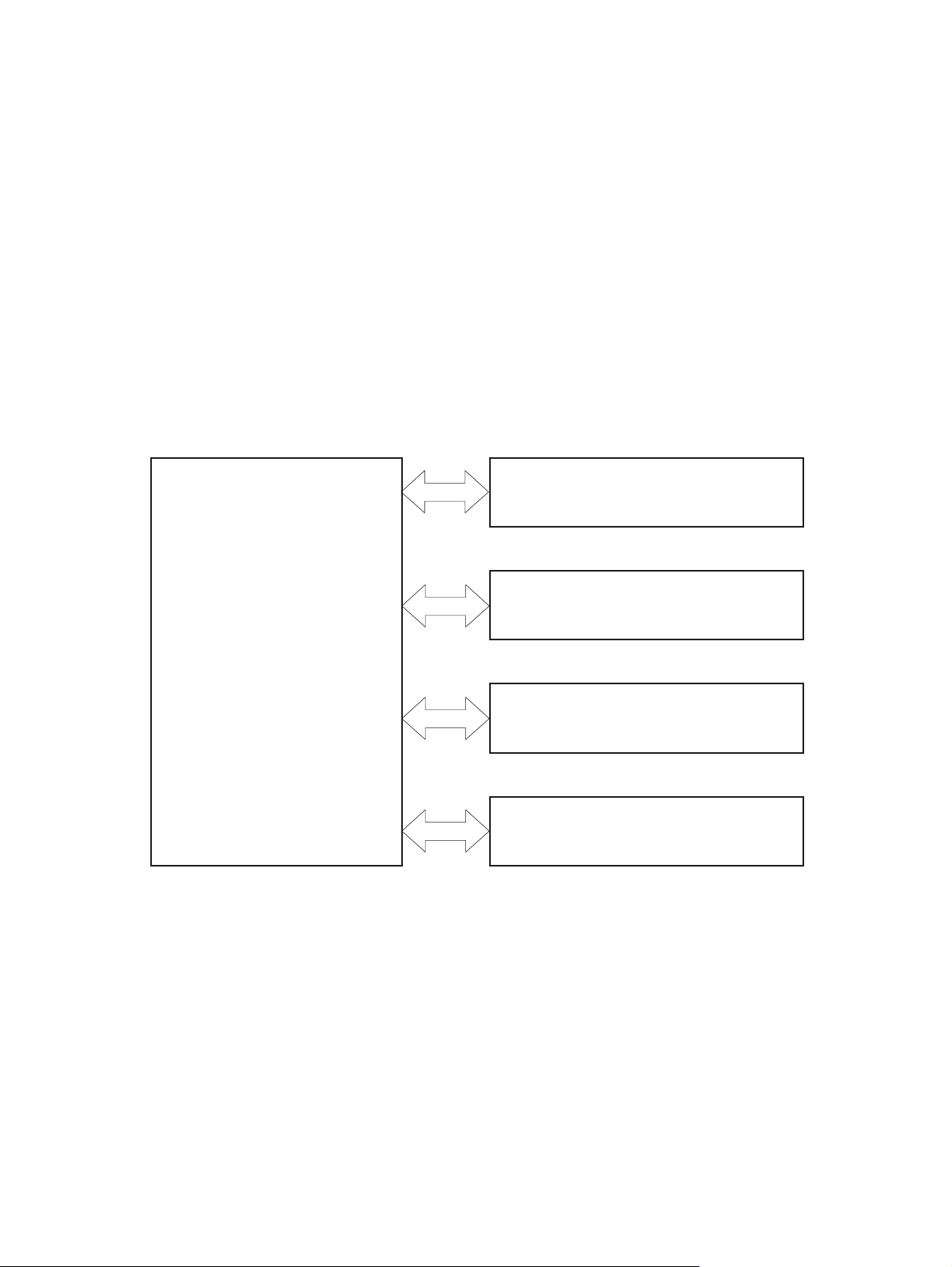
Product block diagram
Figure 1-1 Product block diagram
LASER SCANNER SYSTEM
ENGINE CONTROL SYSTEM
IMAGE-FORMATION SYSTEM
MEDIA FEED SYSTEM
OPTION
2 Chapter 1 Theory of operation ENWW
Page 15

Sequence of operation
The DC controller in the engine-control system controls the operational sequences of the product. The
following table describes durations and operations for each period of a print operation from when the
product is turned on until the motor stops rotating.
Normal sequence of operation
Table 1-1 Sequence of operation
Name Timing Purpose
WAIT From the time the power switch is turned on, the door
STBY (standby) From the end of the WAIT or LSTR period until either
INTR (initial
rotation)
is closed, or the product exits Sleep mode until the
product is ready for a print operation.
a print command is sent or the power switch is turned
off.
From the time the print command is received until the
product picks up a piece of paper.
Brings the product to printable condition:
Detects and heats the fuser
●
Detects the print cartridge and any cartridge
●
changes
Detects the ITB, and moves the ITB and the
●
developing unit to the home position
Cleans residual toner from the ITB and the
●
secondary transfer roller
Maintains the product in printable condition:
Enters Sleep mode if the sleep command is
●
received
Performs a calibration if the calibration
●
command is received
Prepares for the print job
Activates the high-voltage power supply
●
Activates the laser scanner
●
Opens the laser shutter
●
Cleans the protective laser glass
●
Engages the print cartridges
●
Warms the fuser
●
ENWW Basic operation 3
Page 16

Table 1-1 Sequence of operation (continued)
Name Timing Purpose
PRINT From the end of the INTR period until the last sheet
completes the fusing operation.
LSTR (last
rotation)
From the end of the PRINT period until the main motor
stops rotating.
Prints
Forms the image on the photosensitive drum
●
Transfers the toner image to the paper
●
Fuses the toner image to the paper
●
Moves the last printed sheet to the output bin.
Stops the high-voltage power supply
●
Stops the laser scanner
●
Closes the laser shutter
●
Cleans the protective laser glass
●
Disengages the print cartridges
●
Stops the fuser
●
The product enters the INTR period as the LSTR
period is completed, if the formatter sends another
print command.
4 Chapter 1 Theory of operation ENWW
Page 17

Formatter-control system
The formatter is responsible for the following procedures:
Controlling sleep mode
●
Receiving and processing print data from the various product interfaces
●
Monitoring control-panel functions and relaying product-status information (through the control
●
panel and the network or bidirectional interface)
Developing and coordinating data placement and timing with the DC controller PCA
●
Storing font information
●
Communicating with the host computer through the network or the bidirectional interface
●
The formatter receives a print job from the network or bidirectional interface and separates it into image
information and instructions that control the printing process. The DC controller PCA synchronizes the
image-formation system with the paper-input and -output systems, and then signals the formatter to
send the print-image data.
The formatter also provides the electrical interface and mounting locations for an additional DIMM.
Sleep mode
NOTE: In the System Setup menu, this item is termed Sleep Delay.
This feature conserves power after the product has been idle for an adjustable period of time. When the
product is in Sleep Delay, the control-panel backlight is turned off, but the product retains all settings,
downloaded fonts, and macros. The default setting is for Sleep Delay to be enabled, and the product
enters Sleep Delay after a 30-minute idle time.
The product exits Sleep Delay and enters the warm-up cycle when any of the following events occur:
A print job, valid data, or a PML or PJL command is received
●
A control-panel button is pressed
●
A cover is opened
●
A paper tray is opened
●
The engine-test switch is pressed
●
NOTE: Product error messages override the Sleep message. The product enters Sleep Delay at the
appropriate time, but the error message continues to appear.
Input/output
The product has two I/O interfaces:
A USB 2.0 port for connecting directly to a computer
●
An internal 10/100Base-T network port.
●
ENWW Formatter-control system 5
Page 18

CPU
The formatter incorporates a 540 MHz Coldfire processor.
Memory
The random access memory (RAM) on the formatter PCA contains the page, I/O buffers, and the font
storage area. It stores printing and font information received from the host system, and can also serve
to temporarily store a full page of print-image data before the data is sent to the print engine. Memory
capacity can be increased by adding a DIMM to the formatter. Note that adding memory might also
increase the print speed for complex graphics.
NOTE: If the product encounters a problem when managing available memory, a clearable warning
message appears on the control-panel display.
Firmware
The firmware is contained on NAND flash memory soldered on the formatter board. A remote firmware
upgrade process is available, which overwrites the firmware in the NAND flash.
Nonvolatile memory
The product uses nonvolatile memory (NVRAM) to store device and user configuration settings. The
contents of NVRAM are retained when the product is turned off or disconnected.
PJL overview
The printer job language (PJL) is an integral part of configuration, in addition to the standard printer
command language (PCL). With standard cabling, the product can use PJL to perform a variety of
functions such as these:
Two-way communication with the host computer through a network connection or a USB
●
connection. The product can inform the host about such things as the control-panel settings, and
the control-panel settings can be changed from the host.
Dynamic I/O switching. The product uses this switching to be configured with a host on each I/O.
●
The product can receive data from more than one I/O simultaneously, until the I/O buffer is full.
This can occur even when the product is offline.
Context-sensitive switching. The product can automatically recognize the personality (PS or PCL)
●
of each job and configure itself to serve that personality.
Isolation of print environment settings from one print job to the next. For example, if a print job is
●
sent to the product in landscape mode, the subsequent print jobs print in landscape mode only if
they are formatted for landscape printing.
PML
The printer management language (PML) allows remote configuration and status read-back through the
I/O ports.
Control panel
The formatter sends and receives product status and command data to and from the control-panel PCA.
6 Chapter 1 Theory of operation ENWW
Page 19
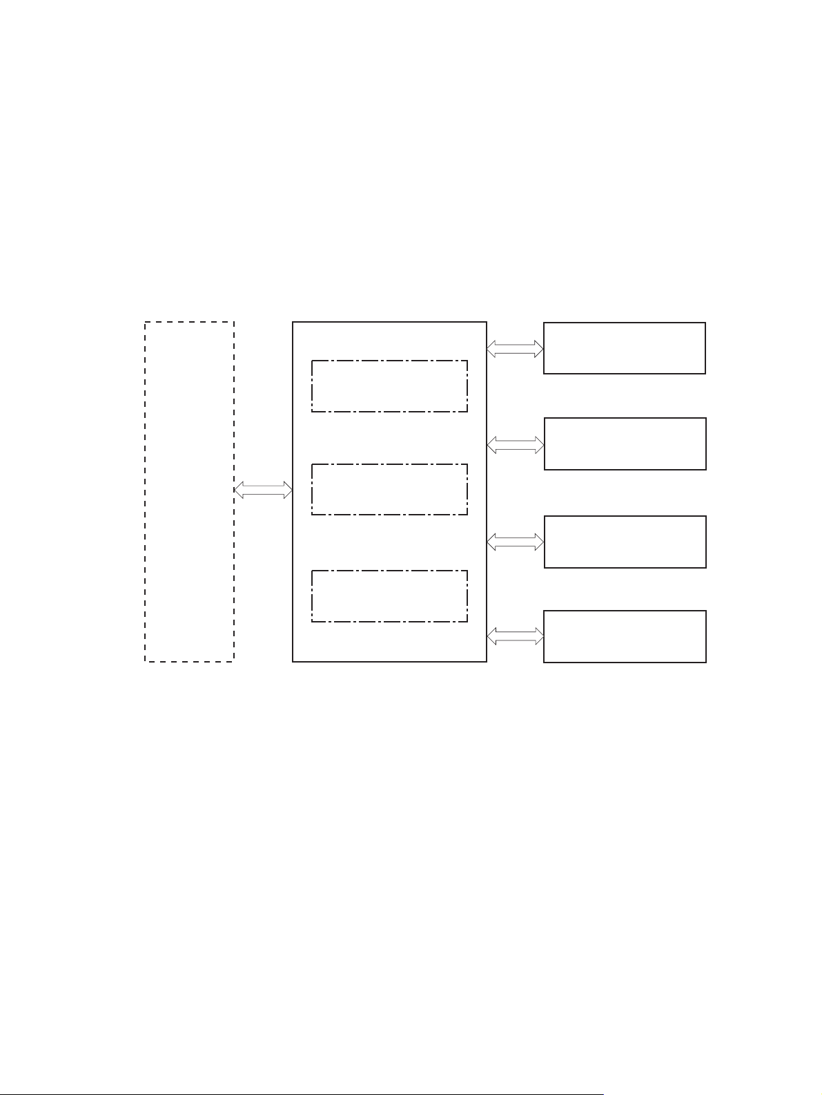
Engine-control system
The engine-control system coordinates all product functions, according to commands that the formatter
sends. The engine-control system drives the laser/scanner system, the image formation system, and
the pickup/feed/delivery system.
The engine control system contains the following major components:
DC controller
●
Low-voltage power supply
●
High-voltage power supply
●
Figure 1-2 Engine-control system
Formatter
ENGINE CONTROL SYSTEM
LASER SCANNER SYSTEM
DC controller
IMAGE-FORMATION SYSTEM
Low-voltage power supply
MEDIA FEED SYSTEM
High-voltage power supply
OPTION
ENWW Engine-control system 7
Page 20
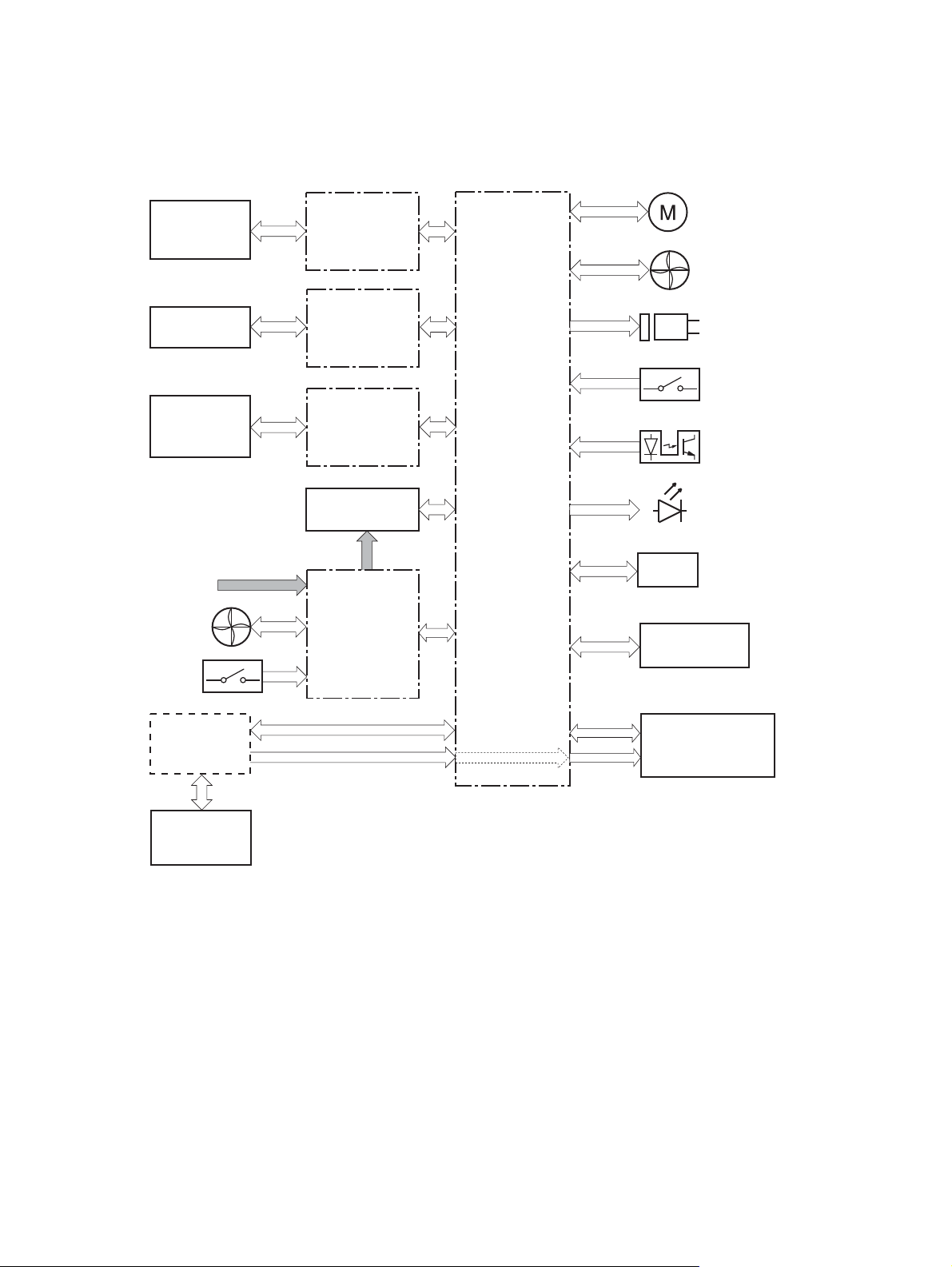
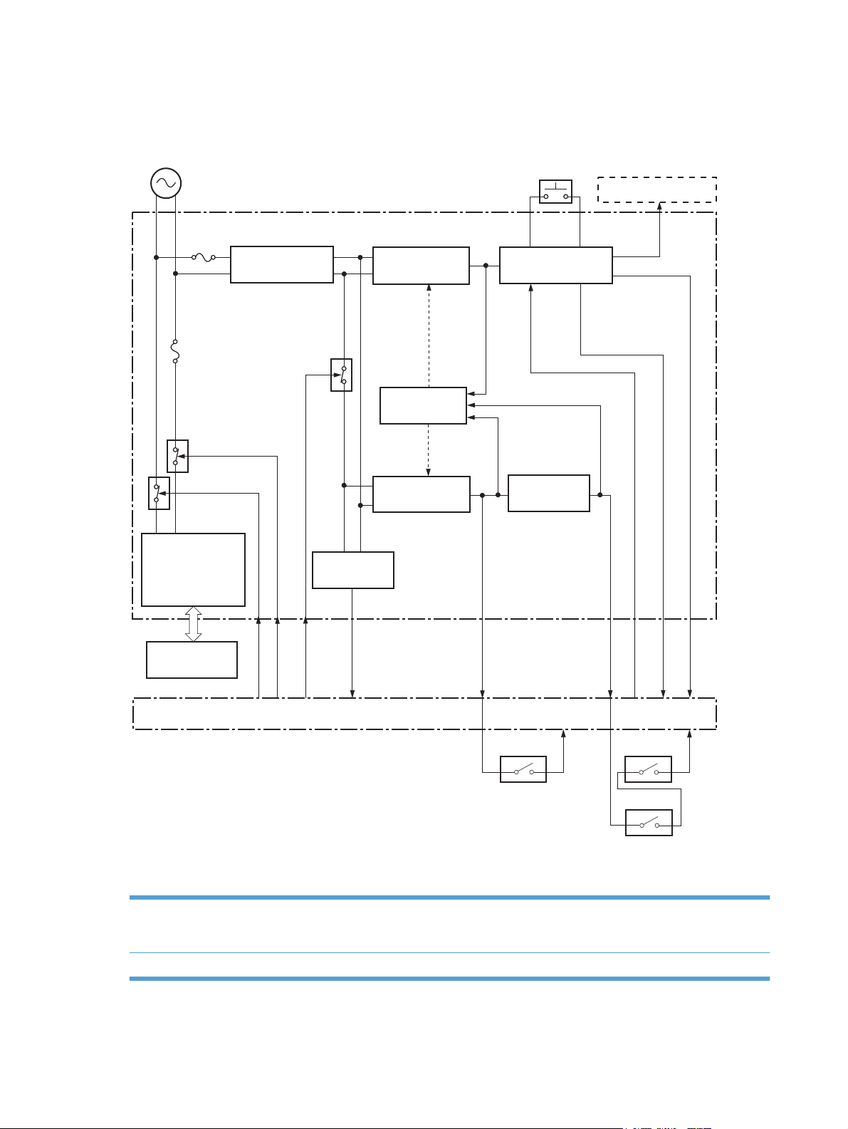
DC controller
The DC controller controls the operational sequence of the product.
Figure 1-3 DC controller diagram
Cartridge
(x4)
ITB unit
Secondary
transfer roller
AC input
Fan
DEV high-voltage
power supply
TR1 high-voltage
power supply
TR2 high-voltage
power supply
Fuser
Low-voltage
power supply
Motor
Fan
Solenoid
Switch
Photointerrupter
DC controller
LED
Sensor
Option
Switch
Formatter
Control
panel
Laser scanner unit
The DC controller controls the product's electrical components, listed in the following table.
8 Chapter 1 Theory of operation ENWW
Page 21

Table 1-2 Electrical components
Component type Abbreviation Name
Switch SW1 Power switch
SW2 24V interlock switch
SW3 5V interlock switch 1
SW4 5V interlock switch 2
SW5 Primary transfer disengagement switch
SW6 Toner collection unit switch
SW7 Cassette media end guide position switch
SW8 Cassette media width guide position switch
Solenoid SL1 Cassette pickup solenoid
SL2 Tray 1 pickup solenoid
SL3 Duplex reverse solenoid 1 (duplex models only)
SL5 Primary transfer disengagement solenoid
SL7 Duplex reverse solenoid 2 (duplex models only)
Fan FM1 Power supply fan
FM2 Fuser fan
Photointerrupter (sensor) PS1 Cassette paper-presence sensor
PS2 Tray 1 paper-presence sensor
PS3 Last-paper sensor
PS4 Cassette paper-stack surface sensor
PS5 Top-of-page (TOP) sensor
PS6 Fuser delivery sensor
PS7 Loop sensor 1
PS8 Loop sensor 2
PS9 Fuser pressure-release sensor
PS10 Output bin full sensor
PS11 Developing disengagement sensor
PS12 Black drum home-position sensor
PS13 YMC drum home-position sensor
PS14 Front door sensor
PS15 Right door sensor
ENWW Engine-control system 9
Page 22

Table 1-2 Electrical components (continued)
Component type Abbreviation Name
Motor M1 ITB Motor
M2 Drum motor
M3 Developing motor
M4 Fuser motor
M5 Pickup motor
M6 Developing disengagement motor
M9 Cassette lifter motor
M10 Scanner motor
10 Chapter 1 Theory of operation ENWW
Page 23
Motors
The product has eight motors for paper feed and image formation. The DC controller determines a motor
failure if a motor does not reach a specified speed within a specified period after motor startup or if the
rotational speed is outside a specified range for a specified period.`
Figure 1-4 Motors
Drum motor (M2)
Developing motor (M3)
Fuser motor (M4)
ITB motor (M1)
Scanner motor (M10)
Developing disengagement motor (M6)
Pickup motor (M5)
Cassette lifter motor (M9)
ENWW Engine-control system 11
Page 24

Table 1-3 Motors
Description Components driven Failure
ITB motor (M1) ITB
Black photosensitive drum
Developing roller
Drum motor (M2) Yellow, magenta, and cyan photosensitive drums Yes
Developing motor (M3) Yellow, magenta, and cyan developing rollers Yes
Fuser motor (M4) Fuser pressure and delivery rollers
Pressurizes and depressurizes the pressure roller
Engages and disengages the primary transfer roller
Pickup motor (M5) Tray 1 pickup roller
Cassette pickup roller
Feed roller
Duplex feed roller (duplex models only)
Developing
disengagement motor
(M6)
Engages and disengages the developing unit No
detection
Yes
Yes
No
Cassette lifter motor
(M9)
Scanner motor (M10) Scanner mirror No
Lifter for the cassette No
12 Chapter 1 Theory of operation ENWW
Page 25
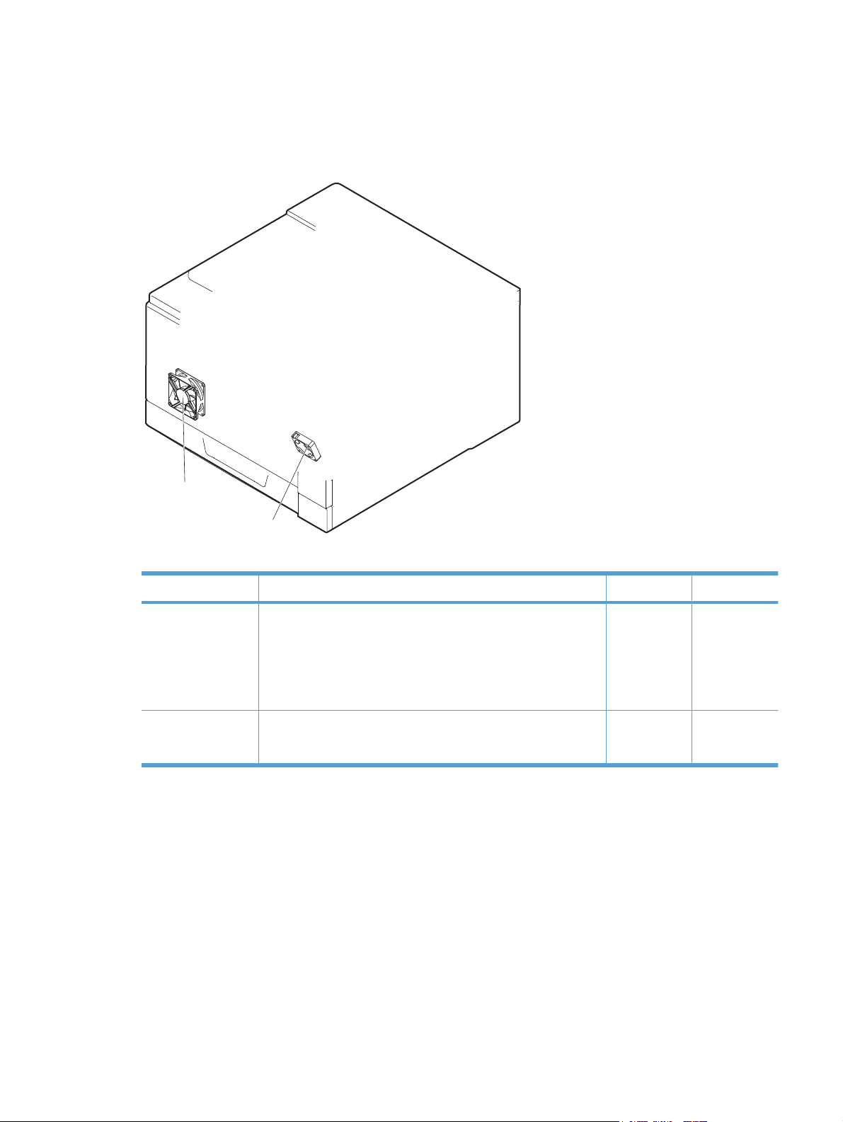
Fans
The product uses to fans to maintain the correct internal temperature. The DC controller determines a
fan failure when a fan locks for a specified period after it starts driving.
Figure 1-5 Fans
Power supply fan
(FM1)
Fuser fan
(FM2)
Table 1-4 Fans
Description Area cooled Type Speed
Power supply fan
(FM1)
Fuser (FM2) Duplex feed unit
Low-voltage power supply
Output bin
Delivery unit
Laser scanner unit
ITB area
Intake Full/Half
Intake Full
ENWW Engine-control system 13
Page 26
Fuser-control circuit
The fuser-control circuit monitors and controls the temperature in the fuser. The product uses ondemand fusing. The fuser-control circuit consists of the following major components:
Fuser main heater (H1): heats the center of the fuser sleeve
●
Fuser sub heater (H2): heats the ends of the fuser sleeve
●
Thermistors; detects the fuser temperature (contact type)
●
Sleeve thermistor (TH1): Detects the temperature at the center of the fuser sleeve
◦
Main thermistor (TH2): Detects the temperature at the center of the fuser heater
◦
Sub thermistor 1 (TH3): Detects the temperature at the end of the fuser heater nearest the
◦
front of the product
Sub thermistor 2 (TH4): Detects the temperature at the end of the fuser heater nearest the
◦
rear of the product
Thermal fuse (FU1): prevents abnormal temperature rise in the fuser heater (non-contact type)
●
Figure 1-6 Fuser-control circuit
TH3
Pressure roller
Front of engine
H2
TH4
Fuser sleeve
H1
TH2
FU1
TH1
FUSER TEMPERATURE signal
FUSER HEATER
CONTROL signal
Low-voltage power supply
Fuser heater
control circuit
DC controller
Fuser heater
safety circuit
14 Chapter 1 Theory of operation ENWW
Page 27
Fuser temperature control
The fuser temperature control maintains the fuser heater at its targeted temperature.
The fuser main heater and sub heater control the temperature of the fuser sleeve.
The DC controller monitors the main thermistor and the sleeve thermistor. The DC controller controls
the FUSER MAIN HEATER CONTROL (FSRD1) and the FUSER SUB-HEATER CONTROL (FSRD2)
signals according to the detected temperature. The fuser-heater control circuit controls the fuser heater
depending on the signal so that the heater remains at the targeted temperature.
Figure 1-7 Fuser-heater control circuit
AC input
Low-voltage power supply
Noise filter
Fuser heater
control circuit
Zerocross
circuit
Improper fuser installation prevention circuit
H2
TH3 TH4
RL102
FU102
RL103
Fuser
Fuser presence circuit
Fuser sleeve
H1
TH2
TH1
FU1
RLD1
RLD2
FSRD1
FSRD2
ZEROX
FUSEROPEN
FUHL
THERM4
THERM2
THERM1
THERM3
DC controller
Fuser heater
safety circuit
ENWW Engine-control system 15
Page 28

Fuser protective function
The protective function detects an abnormal temperature rise of the fuser unit and interrupts power
supply to the fuser heater.
The following three protective components prevent an abnormal temperature rise of the fuser heater:
DC controller
●
The DC controller interrupts power supply to the fuser heater when it detects an abnormal
◦
temperature of the fuser heater.
Fuser-heater safety circuit
●
The fuser heater safety circuit interrupts power supply to the fuser heater when the detected
◦
temperature of the main and sub thermistors is abnormal.
Thermal fuse
●
The thermal fuse is broken to interrupt power supply to the fuser heater when the thermoswitch
◦
detects an abnormal temperature of the fuser heater.
16 Chapter 1 Theory of operation ENWW
Page 29

Fuser failure detection
The DC controller determines a fuser unit failure, deactivates the FUSER HEATER CONTROL signal,
releases the relay to interrupt power supply to the fuser heater and notifies the formatter of a failure
state when it encounters the following conditions:
Abnormal temperature rise: The sleeve thermistor does not rise at a specified temperature within
●
a specified period after the fuser heater control starts.
Abnormally low temperature: The thermistors are at a specified temperature or lower during a print
●
operation or other fuser heating cycle.
Abnormally high temperature: The thermistors are at a specified temperature or higher, regardless
●
of the fuser control status.
Drive circuit abnormality: The frequency in the zerocross circuit is out of a specified range when
●
the product is turned on or is in the standby period.
ENWW Engine-control system 17
Page 30
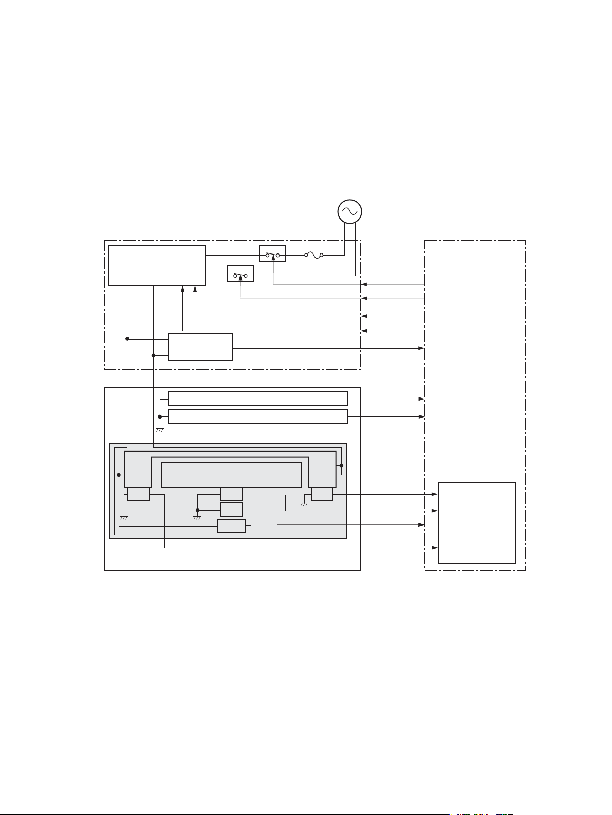
Low-voltage power supply
The low-voltage power supply (LVPS) converts AC input voltage to DC voltage.
Figure 1-8 Low-voltage power supply
Low-voltage power supply
Power switch
SW1
Formatter
FU101
FU102
RL102
RL103
Noise filter
Fuser heater
control circuit
Fuser
Noise filter
Rectifying circuit
RL101
RLD1
RLD2
REMOTEON
Zerocross
circuit
ZEROX
+3.3V generation
circuit
Protection
circuit
+24V generation
circuit
+24V
Remote switch
control circuit
+5V generation
circuit
+5V
+3.3V
PWRON
+3.3V
SWON/OFF
DC controller
SW2
+24R
+24V
Interlock switch
SW4
SW3
+5V
Interlock switch
+5R
The product uses three DC voltages: 24V, 5V, and 3.3V. The voltages are subdivided as follows:
+24V Supplied constantly
Stopped during Sleep mode
+24R Interrupted when the front or right door is opened
18 Chapter 1 Theory of operation ENWW
Page 31

+5V Supplied constantly
Stopped during Sleep mode
+5R Interrupted when the front or right door is opened
+3.3V Supplied constantly
ENWW Engine-control system 19
Page 32

Overcurrent/overvoltage protection
The low-voltage power supply has a protective circuit against overcurrent and overvoltage to prevent
failures in the power supply circuit. The low-voltage power supply automatically stops supplying the DC
voltage whenever excessive current flows or voltage abnormally increases.
If the dc voltage is not being supplied from the low-voltage power supply, the protective function may
be running. In this case, turn off the power switch and unplug the power cord. Do not turn the power
switch on until the root cause is found.
The LVPS has two fuses on the PCA. The LVPS 24V output is interrupted to the fuser and the highvoltage power supply if the either of the interlock switches (SW3 and SW4) is in the off position (door
open).
WARNING! The product power switch only interrupts dc voltage from the LVPS. The AC voltage is
present in the product when the power cord is plugged into a power receptacle and the power switch is
in the off position. You must unplug the product power cord before servicing the product.
WARNING! If you believe the overcurrent or overvoltage protection circuits have been activated, do
not plug in the product power cord or turn on the product power until the cause of the failure is found
and corrected.
In addition, fuses in the low-voltage power supply protect against overcurrent. If overcurrent flows into
the AC line, the fuses melt and cut off the power distribution.
20 Chapter 1 Theory of operation ENWW
Page 33

High-voltage power supply
The DC controller controls the high-voltage power supply to generate biases.
Figure 1-9 High-voltage power supply
TR1 high-voltage power supply
Primary transfer bias circuit
TRI-1
PRI-1
DEV-4
DEV-2
DEV-3
DEV-1
Developing bias circuit
TRI-2
PRI-2
PRI-4
Primary charging bias circuit
PRI-3
TRI-3
TRI-4
FG
Secondary transfer bias circuit
TRS2
DEV high-voltage power supply
DC controller
TR2 high-voltage power supply
The high-voltage power supply (HVPS) applies biases to the following components:
Primary charging roller: The primary charging bias is applied to the surface of the photosensitive
●
drum to charge it uniformly negative as a preparation for the image formation.
Developing roller: The developing bias is used to adhere toner to an electrostatic latent image
●
formed on the photosensitive drum.
ENWW Engine-control system 21
Page 34

Primary transfer roller: The primary transfer bias is used to transfer the toner from each
●
photosensitive drum onto the ITB.
Secondary transfer roller: The secondary transfer bias is used to transfer the toner image from the
●
ITB onto the paper. The reversed bias is applied to transfer residual toner on the secondary transfer
roller back to the ITB. The residual toner on the ITB is deposited in the toner collection unit.
22 Chapter 1 Theory of operation ENWW
Page 35

Laser scanner system
The laser scanner system forms latent images on the photosensitive drums according to the VIDEO
signals sent from the formatter.
The main components of the laser/scanner are the laser unit and the scanner motor unit. The DC
controller sends signals to the laser/scanner to control the functions of these components.
Figure 1-10 Laser/scanner system
Photosensitive drum
Scanner motor unit
Connecting board
SCANNER MOTOR CONTROL signal
VIDEO signal
LASER CONTROL signal
BDI signal
Laser unit (C/Bk)
Laser unit (Y/M)
Scanner mirror
DC controller
Formatter
ENWW Engine-control system 23
Page 36

Laser failure detection
The DC controller determines an optical unit failure and notifies the formatter, if the laser/scanner
encounters the following conditions:
The scanner motor does not reach a specified rotation frequency within a specified period of the
●
scanner motor start up.
The beam detect (BD) interval is out of a specified value during a print operation.
●
24 Chapter 1 Theory of operation ENWW
Page 37

Image-formation system
Electrophotographic process
The electrophotographic process forms an image on the paper. Following are the major components
used in the process:
Print cartridges
●
Intermediate transfer belt (ITB)
●
Secondary transfer roller
●
Fuser
●
Laser scanner
●
The DC controller uses the laser scanner and HVPS to form the toner image on the photosensitive drum.
The image is transferred to the print media and then fused onto the paper.
Figure 1-11 Electrophotographic process block diagram
TR1 high-voltage
Cartridge
power supply
Laser scanner
ITB
DEV high-voltage
power supply
Fuser
Secondary transfer
roller
TR2 high-voltage
power supply
DC controller
ENWW Image-formation system 25
Page 38

Figure 1-12 Electrophotographic process drive system
Drum motor
M2
Developing roller
Developing roller
Developing roller
Fuser motor
M4
Developing roller
Developing motor
M3
M1
ITB motor
26 Chapter 1 Theory of operation ENWW
Page 39

Image formation process
Each of the following processes functions independently and must be coordinated with the other product
processes. Image formation consists of the following processes:
Latent-image formation block Step 1: pre-exposure
Developing block Step 4: developing
Transfer block Step 5: primary transfer
Fusing block Step 8: fusing
ITB cleaning block Step 9: ITB cleaning
Drum cleaning block Step 10: Drum cleaning
Figure 1-13 Image formation process
: Media path
: Direction of drum rotation
: Block
Step 2: primary charging
Step 3: laser-beam exposure
Step 6: secondary transfer
Step 7: separation
Delivery
ITB cleaning
9. ITB cleaning
: Step
4. Developing
Developing
5. Primary transfer
10. Drum cleaning
1. Pre-exposure
2. Primary charging
3. Laser beam exposure
Latent image formation
8. Fuser
Fuser
Transfer
7. Separation
6. Secondary transfer
Drum cleaning
Registration
Pickup
ENWW Image-formation system 27
Page 40

Latent-image formation block
During the latent-image formation stage, the laser scanner forms invisible images on the photosensitive
drums in the print cartridges.
Pre-exposure
Step 1: Light from the pre-exposure LED strikes the photosensitive drum surface. This eliminates the
residual electrical charges on the drum surface.
Figure 1-14 Pre-exposure
LED
Photosensitive drum
Primary charging
Step 2: DC and AC biases are applied to the primary charging roller, which transfers a uniform negative
potential to the photosensitive drum.
Figure 1-15 Primary charging
Primary charging roller
Photosensitive drum
Primary charging bias
28 Chapter 1 Theory of operation ENWW
Page 41

Laser beam exposure
Step 3: The laser beam scans the photosensitive drum to neutralize negative charges on parts of the
drum surface. An electrostatic latent image is formed on the drum where negative charges were
neutralized.
Figure 1-16 Laser beam exposure
Laser beam
ENWW Image-formation system 29
Page 42

Developing block
Step 4: In the print cartridge, toner acquires a negative charge from the friction that occurs when the
developing roller rotates against the developing blade. The developing bias is applied to the developing
roller to create a difference in the electric potential of the drum. When the negatively charged toner
comes in contact with the photosensitive drum, it adheres to the latent image because the drum surface
has a higher potential.
Figure 1-17 Developing
Developing blade
Developing roller
Developing bias
Photosensitive drum
30 Chapter 1 Theory of operation ENWW
Page 43

Transfer block
Primary transfer
Step 5: The toner on the photosensitive drum is transferred to the intermediate transfer belt (ITB). The
ITB is given a positive charge by the bias of the primary transfer roller. The negatively charged toner on
the drum surface is transferred onto the ITB. All four color planes are transferred onto the ITB in this
step.
Figure 1-18 Primary transfer
Primary transfer roller
ITB
Primary transfer bias
Photosensitive
drum
Secondary transfer
Step 6: The toner image on the ITB is transferred to the paper. The secondary transfer bias is applied
to the secondary transfer roller to charge the paper positive. As the paper passes between the secondary
transfer roller and the ITB, the complete toner image on the ITB is transferred onto the paper.
Figure 1-19 Secondary transfer
Secondary transfer roller
Secondary transfer
opposed roller
ITB
Paper
Secondary transfer bias
ENWW Image-formation system 31
Page 44

Separation
Step 7: The elasticity of the paper and the curvature of the secondary transfer opposed roller cause the
paper to separate from the ITB. The static charge eliminator reduces back side static charge of the paper
and controls excess discharge after the transfer process for stable media feed and image quality.
Figure 1-20 Separation
Secondary transfer
opposed roller
ITB
Paper
Static charge eliminator
Secondary transfer roller
Fusing block
Step 8: The product uses an on-demand fuser. The toner image is permanently affixed to the printing
paper by heat and pressure.
Figure 1-21 Fusing
Fuser sleeve
Fuser heater
Toner
Paper
Pressure roller
32 Chapter 1 Theory of operation ENWW
Page 45

ITB cleaning block
Step 9: The cleaning blade scrapes the residual toner off the surface of the ITB. The residual toner feed
screw deposits residual toner in the toner collection unit.
Figure 1-22 ITB cleaning
Residual toner feed screw
Drum cleaning block
Step 10: The cleaning blade scrapes the residual toner off the surface of the photosensitive drum, and
toner is deposited in the waste section inside the print cartridge.
Figure 1-23 Drum cleaning
Cleaning blade
ITB
Cleaning blade
Toner waste
Photosensitive
drum
ENWW Image-formation system 33
Page 46

Print cartridges
The product has four print cartridges, one for each color: yellow, magenta, cyan, and black. Each of
them has the same structure. The cartridges are filled with toner and consist of the following
components:
Photosensitive drum
●
Developing unit
●
Primary charging roller
●
The DC controller rotates the motors to drive the photosensitive drum, developing unit, and primary
charging roller.
Figure 1-24 Print cartridge block diagram
DC controller
PS13:
YMC drum home
position sensor
Memory tag
Developing
M6
disengagement
motor
Photosensitive drum
Primary charging roller
Developing unit
PS11:
Developing disengagement
sensor
M2
Drum motor
M3
Developing motor
34 Chapter 1 Theory of operation ENWW
Page 47

Memory tag
The memory tag is a non-volatile memory chip in the cartridge that stores information about usage for
the cartridge. The product reads and writes the data in the memory tag. The DC controller determines
a memory tag error and notifies the formatter when it fails to either read from or write to the memory
tag.
Cartridge presence detection
The DC controller detects the presence of the cartridges by monitoring the RD sensor. When the DC
controller determines a cartridge absence, it notifies the formatter.
Toner level detection
The DC controller detects the remaining toner level in a cartridge by the optical detection method. The
DC controller notifies the formatter of the remaining toner level.
Cartridge life detection
The DC controller detects the cartridge life by monitoring the total operational wear limit or remaining
toner level of the cartridge. The DC controller determines a cartridge end of life and notifies the formatter
when the operational wear limit of the cartridge reaches a specified amount or the cartridge runs out of
toner.
Developing unit engagement and disengagement control
The developing unit engagement and disengagement control engages the developing unit with the
photosensitive drum or disengages the developing unit from the drum depending on the print mode: fullcolor mode or black-only mode. The developing unit is engaged only when required, preventing a
deterioration of the drums and maximizing their life.
The developing disengagement motor rotates the developing disengagement cam. As the cam rotates,
the developing unit engages with or separates from the photosensitive drum.
When the product is turned on and when each print job is completed, all four of the developing units
disengage from the photosensitive drums. When the print mode is in full-color mode, all of the developing
units engage with the drums. When the print mode is in black-only mode, only black developing unit
engages with the drum.
ENWW Image-formation system 35
Page 48

The DC controller determines a developing disengagement motor abnormality and notifies the formatter
when it does not detect a specified signal from the developing disengagement sensor during the
developing roller engagement and disengagement operation.
Figure 1-25 Developing unit engagement and disengagement control
Developing unit is disengaged
Photosensitive drum
Developing unit
PS11:
Developing
disengagement
sensor
Developing disengagement cam
Developing unit is engaged
Developing disengagement motor
M6
DC controller
36 Chapter 1 Theory of operation ENWW
Page 49

ITB unit
The ITB unit receives the toner image from the photosensitive drums and transfers the complete toner
image to the print media. The ITB unit consists of the following components:
ITB
●
ITB drive roller
●
Primary transfer rollers
●
ITB cleaner
●
The ITB motor drives the ITB drive roller which rotates the ITB. The rotation of the ITB causes the primary
transfer rollers to rotate. The ITB cleaner cleans the ITB surface.
Figure 1-26 ITB unit block diagram
DC controller
ITB
ITB cleaner
Primary transfer roller
ITB drive roller
M1
ITB motor
ENWW Image-formation system 37
Page 50

Primary transfer roller engagement and disengagement control
Figure 1-27 Primary transfer roller engagement and disengagement control
DC controller
M4
Fuser motor
<All colors are disengaged>
YMC slide plate
<All colors are engaged>
Primary transfer
disengagement solenoid
ITB
Primary transfer roller
SL5
SW5
Bk slide plate
Primary transfer
disengagement switch
Primary transfer
disengagement cam
<Only black is engaged>
Photosensitive drum
38 Chapter 1 Theory of operation ENWW
Page 51

The primary transfer roller engagement and disengagement control engages the ITB with the
photosensitive drum or disengages the ITB from the drum depending on the requirements of the print
job. There are three states of the primary transfer rollers.
All rollers disengaged: The ITB disengages from all the four photosensitive drums. This is the
●
state during a standby period, and it is the home position for the primary transfer rollers.
All rollers engaged: The ITB engages with all the four photosensitive drums. This is the state for
●
full-color jobs.
Only black roller engaged: The ITB engages with only the black photosensitive drum. This is the
●
state for the black-only jobs.
The operational sequence of the primary transfer roller engagement and disengagement control is as
follows:
1. The fuser motor drives the primary transfer disengagement solenoid to rotate the primary transfer
disengagement cam.
2. As the cam rotates, the YMC slide plate or the Bk slide plate moves to right or left. This causes the
primary transfer roller to move up or down.
3. The ITB engages with or disengages from the photosensitive drum depending on the movement
of the primary transfer rollers.
The DC controller determines an abnormal primary transfer roller disengagement mechanism and
notifies the formatter when it does not detect a specified signal from the primary transfer disengagement
switch even though the primary transfer disengagement solenoid is driven.
ITB unit presence detection
The DC controller detects the ITB unit presence by monitoring the primary transfer disengagement
switch. The DC controller drives the primary transfer disengagement solenoid for specified times during
the initial rotation period of the following:
The product is turned on
●
The product exits Sleep mode
●
The door is closed
●
The DC controller determines an ITB unit absence and notifies the formatter when it does not detect a
specified signal from the primary transfer disengagement switch.
ITB cleaning mechanism
The cleaning blade in the ITB cleaner scrapes the residual toner off the ITB surface. The ITB motor
drives the residual toner feed screw and the screw deposits the residual toner in the toner collection
unit.
The DC controller detects whether the toner collection unit is full by monitoring the ITB residual toner
full sensor. When the DC controller determines the toner collection unit is full, it notifies the formatter.
ENWW Image-formation system 39
Page 52

The DC controller also detects the presence of the toner collection unit by monitoring the toner collection
unit switch.
Figure 1-28 ITB cleaning mechanism
DC controller
SW6
Toner collection unit switch
ITB residual toner full sensor
Toner collection unit
ITB
Cleaning blade
ITB cleaner
Residual toner feed screw
M1
ITB motor
Calibration
The product calibrates itself to print a high-quality image. The calibration corrects a color-misregistration
and color-density variation caused by environment changes or variation inherent in the product. The
product performs the following calibrations:
Color-misregistration control
●
Environment change control
●
Image stabilization control
●
Color-misregistration control
The color-misregistration control corrects the misaligned color caused by the variation inherent in the
laser scanner units or cartridges. The color-misregistration control corrects the following:
Horizontal scanning start position
●
Horizontal scanning magnification
●
Vertical scanning start position
●
40 Chapter 1 Theory of operation ENWW
Page 53

The DC controller forms pattern of toner on the surface of the ITB and measures a misaligned length
with the RD sensor and the RDL sensor. Accordingly, the formatter calibrates the color-misregistration.
Figure 1-29 Color-misregistration control
RD sensor
RDL sensor
ITB
Pattern of toner
The DC controller commands the formatter to perform the color-misregistration control whenever one
of the following occurs:
The product is turned on or the door is closed, after replacing any one of the cartridges
●
The product is turned on or the door is closed, after replacing the ITB unit or the laser scanner unit
●
A specified number of pages have been printed
●
Continuous printing for a specified period of time
●
Cold starting of the fuser when the product is turned on
●
If data from the RD or RDL sensor is out of a specified range during the cartridge-presence detection
or when starting the color-misregistration control, the DC controller determines an abnormal sensor and
notifies the formatter.
Environment change control
The environment change control calibrates each high-voltage bias to obtain an appropriate image
according to the environment changes. The DC controller determines the environment, where the
product is installed, based on the surrounding temperature and humidity data from the environment
sensor. It adjusts the high-voltage biases to accommodate environmental changes.
The DC controller determines an environment sensor abnormality and notifies the formatter when it
detects out of specified range data from the environment sensor.
Image stabilization control
The image stabilization control reduces the fluctuations in image density caused by environmental
changes or deterioration of the photosensitive drums or toner. The two kinds of image stabilization
controls are image density control (DMAX) and image halftone control (DHALF).
ENWW Image-formation system 41
Page 54

Image density control (DMAX)
The image density control calibrates each high-voltage bias to stabilize the image density variation
caused by the deterioration of the photosensitive drum or toner. The DC controller commands the
formatter to control the image density under the following conditions:
The detected temperature of the fuser is a specified degree or lower when the product is turned
●
on
The product is turned on or the door is closed and also whenever a specified number is printed
●
after replacing any one of the cartridges
The product is turned on or the door is closed after replacing the ITB unit or the laser scanner unit
●
A specified number of pages have been printed
●
After a specified period of time from the previous image density control
●
The environment is changed for a specified condition after the previous image density control
●
Image halftone control (DHALF)
The image halftone control is performed by the formatter to calibrate the halftone. The DC controller
measures the halftone pattern according to a command from the formatter. Accordingly, the formatter
calibrates the halftone. The DC controller controls the image halftone under the following conditions:
The image density control is completed
●
The formatter sends a command
●
42 Chapter 1 Theory of operation ENWW
Page 55

Pickup, feed, and delivery system
The pickup/feed/delivery system consists of several types of feed rollers and sensors. The duplex model
has a mechanism that reverses and refeeds the print media to print two sides automatically.
Figure 1-30 Pickup, feed, and delivery system
Fuser sleeve
Pressure roller
Duplex feed roller
(duplex model)
Secondary transfer roller
MP tray pickup roller
MP tray separation pad
Simplex media path
Duplex media path (duplex model)
CST pickup roller
CST separation roller
The pickup/feed/delivery system can be divided into the following three blocks:
Pickup-and-feed block: From each input source to the fuser inlet
●
Fuser-and-delivery block: From the fuser to the output bin
●
Duplex block: From the duplex reverse unit to the duplex re-pickup unit (duplex models only)
●
Figure 1-31 Pickup, feed, and delivery system blocks
Fuser-and-delivery block
Duplex block
Pickup-and-feed block
ENWW Pickup, feed, and delivery system 43
Page 56

Photo sensors
Figure 1-32 Photo sensors (paper path)
PS10
PS6
PS7
PS8
PS5
PS2
PS1
PS4
Table 1-5 Photo sensors and switches (product)
Item Description Item Description
PS1 Cassette paper-presence sensor PS6 Fuser delivery sensor
PS2 Tray 1 (MP tray) paper-presence sensor PS7 Loop sensor 1
PS3 Last-paper sensor PS8 Loop sensor 1
PS3
PS4 Cassette paper-stack surface sensor PS10 Output bin media-full sensor
PS5 Top-of-Page (TOP) sensor
44 Chapter 1 Theory of operation ENWW
Page 57

Motors and solenoids
Figure 1-33 Motors and solenoids (paper path)
For duplex model only
M4
SL3
SL7
M9
M1
SL2SL1
M5
Table 1-6 Motors and solenoids (paper path)
Item Description Item Description
M1 ITB motor SL1 Cassette pickup solenoid
M4 Fuser motor SL2 Tray 1 (MP tray) pickup solenoid
M5 Pickup motor SL3 Duplex reverse solenoid 1 (duplex models only)
M9 Cassette lifter motor SL7 Duplex reverse solenoid 2 (duplex models only)
Pickup and feed block
The pickup-and-feed block picks one sheet of paper from the cassette or the MP tray and feeds it into
the fuser.
Cassette pickup
The operational sequence of the cassette pickup is as follows:
1. The product is turned on or the cassette is inserted.
2. The lift-up operation and the lifting plate spring move up the lifting plate to the position where the
paper can be picked up.
3. The DC controller rotates the pickup motor when it receives a print command from the formatter.
ENWW Pickup, feed, and delivery system 45
Page 58

4. The cassette (CST) feed roller rotates.
5. The cassette (CST) pickup solenoid is driven at a specified timing.
6. The cassette (CST) pickup roller rotates and picks up the paper.
7. The cassette (CST) separation roller removes any multiple-fed sheets.
8. One sheet of paper is fed into the product.
NOTE: The lift-up operation pushes up the lifting plate to keep the stack surface of paper at the pickup
position.
Figure 1-34 Cassette pickup operation
DC controller
Pickup motor
M5
CST pickup solenoid
SL1
CST pickup roller
Cassette multiple-feed prevention
The product uses a separation roller method to prevent multiple sheets of print media from entering the
paper path. The cassette separation roller does not have its own driving force. Therefore the cassette
separation roller follows the rotation of the cassette pickup roller.
During normal feed, when the product picks up one piece of paper, the cassette separation roller is
driven by the cassette pickup roller through one sheet of paper. Thus the separation roller rotates in the
paper feed direction.
CST feed roller
CST separation roller
Lifting plate spring
Lifter
During multiple-feed, when the product picks up more than one piece of paper, the low friction force
between the sheets weakens the driving force from the cassette pickup roller. In addition, some braking
46 Chapter 1 Theory of operation ENWW
Page 59

force is always applied to the cassette separation roller, so the weak rotational force of the pickup roller
is not enough to rotate the separation roller. Therefore, the separation roller holds back any multiplefed sheets, and one sheet of paper is fed into the product.
Figure 1-35 Cassette multiple-feed prevention
CST Pickup roller
Print media
CST separation roller
Lifting plate
<Normal-feed> <Multiple-feed>
Tray 1 (MP tray) paper pickup
The operational sequence of the MP tray pickup is as follows:
1. The DC controller rotates the pickup motor when it receives a print command from the formatter.
2. As the MP tray pickup solenoid is driven, the MP tray pickup roller rotates and the lifting plate moves
up.
3. The MP tray pickup roller picks up the paper.
4. The MP tray separation pad removes any multiple-fed sheets and one sheet of paper is fed into
the product.
The separation roller does not rotate
ENWW Pickup, feed, and delivery system 47
Page 60

The MP tray media presence sensor detects the presence of print media on the MP tray.
Figure 1-36 Tray 1 (MP tray) paper pickup
DC controller
Pickup motor
MP tray pickup solenoid
MP tray pickup roller
Tray 1 (MP tray) last-paper detection
M5
PS2:
MP tray media presence sensor
SL2
Lifting plate
MP tray separation pad
The product detects whether the print media on the MP tray is the last sheet during continuous printing
to prevent toner contamination on the photosensitive drums and the ITB.
The product attempts to form the next image before the DC controller detects a media absence because
the paper path between the MP tray media-presence sensor and the registration roller is short. To
prevent the photosensitive drums and the ITB from being contaminated with toner, the last-paper sensor
detects the last-paper. The MP tray last-paper detection roller rotates when the last-paper is picked up.
48 Chapter 1 Theory of operation ENWW
Page 61

The DC controller notifies the formatter of a media absence when it detects the last-paper by the lastpaper sensor.
Figure 1-37 Tray 1 (MP tray) last-paper detection
DC controller
Feed direction
Paper feed
After the paper pickup operation, the paper picked up from either the cassette or MP tray is then fed to
the fixing-and-delivery block.
1. The registration shutter corrects the skew-feeding of the paper that is picked up from the cassette
2. When the TOP sensor detects the leading edge of paper, the DC controller controls the rotational
3. The toner image on the ITB is transferred onto the paper, and the paper is fed to the fusing-and
Last-paper
A
MP tray last-paper detection roller
Cross sectional view from A direction
PS3:
Last-paper sensor
or MP tray.
speed of the pickup motor to align with the leading edge of toner image on the ITB.
delivery block.
ENWW Pickup, feed, and delivery system 49
Page 62

The DC controller notifies the formatter of a paper size mismatch error when the paper length detected
by the TOP sensor does not match the paper size specified by the formatter.
Figure 1-38 Paper feed
DC controller
TOP sensor
Registration shutter
Registration roller
ITB motor
PS5
M1
Pickup motor
M5
50 Chapter 1 Theory of operation ENWW
Page 63

Skew-feed prevention
The printer corrects the skew feed without decreasing the throughput.
1. The leading edge of paper strikes the registration shutter and aligns.
2. As the feed rollers keep pushing the paper, the paper gets warped against the registration shutter.
3. The stiffness of paper pushes up the registration shutter and the realigned paper passes through
straightened.
Figure 1-39 Skew-feed prevention
Registration shutter
Registration shutter
Paper
Paper
ENWW Pickup, feed, and delivery system 51
Page 64

Feed-speed control
The product adjusts the feed speed to obtain the best print quality depending on the type of print media.
The product prints at the speed corresponding to the print mode specified by the formatter.
Print mode Feed speed Print mode Feed speed
Normal Full Photo media 1 Half
Heavy media 1 Full Photo media 2 Half
Heavy media 2 Half Photo media 3 Half
Heavy media 3 Half Envelope Full
Light media 1 Full OHT Half
Glossy media 1 Half Label Half
Glossy media 2 Half Rough Full
Glossy media 3 Half Normal gloss Full
Glossy film Half
Fusing and delivery block
The fusing-and-delivery block fuses the toner image onto the print media and delivers the printed page
to the output bin.
Loop control
The product controls the loop (slackness) of print media to prevent the defects of print quality and media
feed.
●
●
If the fuser sleeve rotates slower than the ITB, the paper loop increases and an image defect or
paper crease occurs.
If the fuser sleeve rotates faster than the ITB, the paper loop decreases and an image is stretched
because the toner image is not transferred to the paper correctly
52 Chapter 1 Theory of operation ENWW
Page 65

Two loop sensors located between the fuser sleeve and the ITB detect the paper loop. Accordingly the
DC controller controls the rotational speed of the fuser motor to keep the loop amount properly.
Loop sensor 1: Detects the paper loop for heavy media
●
Loop sensor 2: Detects the paper loop for plain media other than heavy media
●
Figure 1-40 Loop control
DC controller
Sensor flag for heavy paper
Fuser motor
Fuser sleeve
Pressure roller
M5
PS8
PS7
Loop sensor2
Loop sensor1
Sensor flag for other than heavy paper
Fuser sleeve
ITB
Loop sensor1
OFF
ON
ON
<A>
Small-loop
Loop sensor2
Pressure roller
OFF
OFF
ON
<B>
Large-loop
(heavy media)
Speed of fuser motor
Speed down
Heavy media: Speed up
Other media: Speed down
Speed up
<C>
Large-loop
(other than heavy media)
Illus.
A
B
C
ENWW Pickup, feed, and delivery system 53
Page 66

Pressure roller pressurization and depressurization control
The product releases the pressure roller from the fuser sleeve, except during printing, to prevent
deforming the fuser sleeve and the pressure roller and to facilitate the jam-clearing procedure.
1. The DC controller reverses the fuser motor to rotate the fixing pressure release cam.
2. The pressure roller is pressurized or depressurized depending on the position of the cam.
The DC controller determines a fuser pressure-release mechanism abnormality and notifies the
formatter when it does not sense the fuser pressure-release sensor for a specified period from when it
reverses the fuser motor.
Figure 1-41 Pressure roller pressurization and depressurization control
DC controller
Fuser motor
M4
PS9:
Fuser pressure release sensor
Fuser pressure release cam
Fuser sleeve
<Pressurized> <Depressurized>
Pressure roller
54 Chapter 1 Theory of operation ENWW
Page 67

Output bin full detection
The output bin media-full sensor detects whether the output bin is full of printed pages. The DC controller
determines the output bin is full and notifies the formatter when it senses the output bin media-full sensor
is on for a specified period during standby or printing.
Figure 1-42 Output bin full detection
DC controller
Output bin media full sensor
Output bin media full sensor flag
PS10
ENWW Pickup, feed, and delivery system 55
Page 68

Duplex block (duplex models only)
The duplex reverse control reverses the paper after the first side is printed. The duplex feed control
feeds the paper to the duplex block to print the second side of the page.
Figure 1-43 Duplex operation
DC controller
M4
Fuser motor
SL3
Duplex reverse solenoid 1
SL7
Duplex reverse solenoid 2
Pickup motor
M5
Delivery roller
Duplex media path
Duplex feed roller
Duplex block
1. The DC controller controls the duplex reverse solenoid 1 and duplex reverse solenoid 2 at a
specified timing after the first side is printed.
Duplex reverse solenoid 1 Duplex reverse solenoid 2 Delivery roller
Off Off Rotates
On Off Stops
On On Reverses
2. The DC controller reverses the delivery roller and the paper is reversed.
3. The duplex feed roller feeds the paper.
56 Chapter 1 Theory of operation ENWW
Page 69

Jam detection
The product uses the following sensors to detect the presence of print-media and to check whether the
print-media is being fed correctly or has jammed:
TOP sensor (PS5)
●
Fuser delivery sensor (PS6)
●
Loop sensor 1 (PS7)
●
Loop sensor 2 (PS8)
●
Output bin media full sensor (PS10)
●
Figure 1-44 Sensors for jam detection
PS10
PS6
PS7
PS8
PS5
Simplex media path
Duplex media path (duplex model)
The product detects the following jams:
Pickup delay jam Tray 1 (MP tray): The TOP sensor does not detect the leading edge of paper within a specified
Pickup stationary jam The TOP sensor does not detect the trailing edge of paper within a specified period after the
Fuser delivery delay jam The fuser delivery sensor does not detect the leading edge of paper within a specified period
Fuser delivery stationary jam The fuser delivery sensor does not detect the trailing edge of paper within a specified period
period, including a retry, after the MP tray pickup solenoid is turned on.
Cassette: The TOP sensor does not detect the leading edge of paper within a specified period,
including a retry, after the cassette pickup solenoid is turned on.
Paper feeder: The TOP sensor does not detect the leading edge of paper within a specified
period after the paper-feeder (PF) feed sensor detects the leading edge.
leading edge of paper reaches the secondary transfer roller unit.
after the leading edge of paper reaches the secondary transfer roller unit.
after the TOP sensor detects the trailing edge.
The output bin media full sensor does not detect the leading edge of paper within a specified
period after the fuser delivery sensor detects the leading edge.
ENWW Pickup, feed, and delivery system 57
Page 70

Wrapping jam The fuser delivery sensor detects a paper absence yet it does not detect the trailing edge of
paper after it detects the leading edge.
Residual paper jam One of the following sensors detects a presence of paper when the printer is turned on or when
Door open jam The door open is detected during a paper feed operation.
Duplex re-pickup jam (duplex
model only)
the door is closed.
TOP sensor
●
Fuser delivery sensor
●
Loop sensor 1
●
Loop sensor 2
●
NOTE: The product automatically clears all paper from the paper path if the TOP sensor
detects residual paper when the product is turned on or a door is closed.
The TOP sensor does not detect the leading edge of paper within a specified period after the
paper is reversed during a duplex print operation.
58 Chapter 1 Theory of operation ENWW
Page 71

Paper feeder
This product supports an optional 500-sheet tray (Tray 3). The operational sequence of the paper feeder
is controlled by the paper feeder controller PCA.
Figure 1-45 Paper-feeder paper path
PF pickup roller
PF separation roller
PF feed roller
Figure 1-46 Paper-feeder block diagram
Paper feeder
Motor
+3.3V
DC controller
+24V
Paper feeder
controller
Solenoid
Photointerrupter
Switch
ENWW Paper feeder 59
Page 72

Paper-feeder motors
The paper feeder has two motors for paper feed and cassette lift-up operation.
Figure 1-47 Paper-feeder motors
Table 1-7 Paper-feeder motors
Motor Driving part Failure detection
PF lifter motor (M2)
PF pickup motor (M1)
PF pickup motor (M1) PF pickup roller
PF separation roller
PF feed roller
PF lifter motor (M2) Lifter for the PF cassette No
No
60 Chapter 1 Theory of operation ENWW
Page 73

Paper-feeder paper pickup and feed
The pickup-and-feed operation picks up one sheet of print media in the paper-feeder cassette and feeds
it to the product.
Figure 1-48 Paper-feeder electrical components
SR1
SW2SW3
Table 1-8 Paper-feeder electrical components
Component type Abbreviation Description
Motor M1 PF pickup motor
M2 PF lifter motor
Solenoid SL01 PF pickup solenoid
Photointerruptor (sensor) SR1 PF paper-feed sensor
SR2 PF paper-stack surface sensor
SR3 PF cassette paper-presence sensor
SR2
SR3
M2
SW1
SL1
M1
Switch SW1 PF door-open switch
SW2 PF cassette paper end-plate position switch
SW3 PF cassette paper-width switch
Paper-feeder cassette lift operation
The cassette lift-up operation keeps the surface of the paper stack at the pickup position whenever the
following occurs:
Product is turned on
●
Cassette is inserted
●
Stack surface in the cassette lowers
●
ENWW Paper feeder 61
Page 74

The operational sequence of the cassette lift-up is as follows:
1. The PF lifter motor rotates to raise the lifter.
2. When the PF paper-stack surface sensor detects the surface of the paper stack, the PF lifter motor
stops.
3. The lifter motor rotates again when the PF paper-stack surface detects that the paper surface is
lowered during a print operation.
The paper feeder controller PCA determines a PF lifter motor failure and notifies the formatter through
the DC controller when the PF paper-stack surface sensor does not detect the stack surface within a
specified period after the PF lifter motor starts rotating.
Figure 1-49 Paper-feeder cassette lift operation
PF cassette media presence sensor
Paper-feeder jam detection
The paper feeder uses the PF paper-feed sensor (SR1) to detect the presence of print-media and to
check whether print-media is being fed correctly or has jammed.
Figure 1-50 Paper-feeder jam detection
Paper feeder 1
SR3
PF media stack surface sensor
Lifting plate
Lifter
PF lifter motor
SR2
PF cassette media presence sensor flag
PF media stack surface flag
M2
SR1
The paper feeder detects the following jams:
PF pickup delay jam The PF paper-feed sensor does not detect the leading edge of paper within a specified period,
including a retry, after the PF pickup solenoid is turned on.
PF residual paper jam The PF paper-feed sensor detects a presence of paper when the printer is turned on, when the
PF door open jam A door open is detected during paper-feed operation.
door is closed or when the automatic delivery is performed.
62 Chapter 1 Theory of operation ENWW
Page 75

2 Removal and replacement
Introduction
●
Removal and replacement strategy
●
Electrostatic discharge
●
Required tools
●
Service approach
●
Removal and replacement procedures
●
ENWW 63
Page 76

Introduction
This chapter describes the removal and replacement of field-replaceable units (FRUs) only.
Replacing FRUs is generally the reverse of removal. Occasionally, notes and tips are included to provide
directions for difficult or critical replacement procedures.
HP does not support repairing individual subassemblies or troubleshooting to the component level.
Note the length, diameter, color, type, and location of each screw. Be sure to return each screw to its
original location during reassembly.
Incorrectly routed or loose wire harnesses can interfere with other internal components and can become
damaged or broken. Frayed or pinched harness wires can be difficult to find. When replacing wire
harnesses, always use the provided wire loops, lance points, or wire-harness guides and retainers.
64 Chapter 2 Removal and replacement ENWW
Page 77

Removal and replacement strategy
WARNING! Turn the product off, wait 5 seconds, and then remove the power cord before attempting
to service the product. If this warning is not followed, severe injury can result, in addition to damage to
the product. The power must be on for certain functional checks during troubleshooting. However,
disconnect the power supply during parts removal.
Never operate or service the product with the protective cover removed from the laser/scanner
assembly. The reflected beam, although invisible, can damage your eyes.
The sheet-metal parts can have sharp edges. Be careful when handling sheet-metal parts.
CAUTION: Do not bend or fold the flat flexible cables (FFCs) during removal or installation. Also, do
not straighten pre-folds in the FFCs. You must fully seat all FFCs in their connectors. Failure to fully
seat an FFC into a connector can cause a short circuit in a PCA.
NOTE: To install a self-tapping screw, first turn it counterclockwise to align it with the existing thread
pattern, and then carefully turn it clockwise to tighten. Do not overtighten. If a self-tapping screw-hole
becomes stripped, repair the screw-hole or replace the affected assembly.
TIP: For clarity, some photos in this chapter show components removed that would not be removed
to service the product. If necessary, remove the components listed at the beginning of a procedure
before proceeding to service the product.
ENWW Removal and replacement strategy 65
Page 78

Electrostatic discharge
CAUTION: Some parts are sensitive to electrostatic discharge (ESD). Look for the ESD reminder
when removing product parts. Always perform service work at an ESD-protected workstation or mat, or
use an ESD strap. If an ESD workstation, mat, or strap is not available, ground yourself by touching the
sheet-metal chassis before touching an ESD-sensitive part.
Protect the ESD-sensitive parts by placing them in ESD pouches when they are out of the product.
66 Chapter 2 Removal and replacement ENWW
Page 79

Required tools
#2 Phillips screwdriver with a magnetic tip and a 152-mm (6-inch) shaft length
●
Small flat blade screwdriver
●
Needle-nose pliers
●
ESD mat or ESD strap (if one is available)
●
Penlight (optional)
●
CAUTION: Always use a Phillips screwdriver (callout 1). Do not use a pozidrive screwdriver (callout 2)
or any motorized screwdriver. These can damage screws or screw threads.
Figure 2-1 Phillips and pozidrive screwdriver comparison
ENWW Required tools 67
Page 80

Service approach
Before performing service
Remove all media from the product.
●
Turn off the power using the power switch.
●
Unplug the power cable and interface cable or cables.
●
Place the product on an ESD workstation or mat, or use an ESD strap (if one is available). If an
●
ESD workstation, mat, or strap is not available, ground yourself by touching the sheet-metal chassis
before touching an ESD-sensitive part.
Remove the print cartridges. See
●
Remove the tray cassette or cassettes.
●
After performing service
Plug in the power cable.
●
Reinstall the print cartridges.
●
Reinstall the tray cassette or cassettes.
●
If the optional paper feeder was removed for service, place the product on the feeder. Engage the
●
optional feeder tray locks to secure the feeder to the product.
Post-service test
Perform the following test to verify that the repair or replacement was successful.
Print-quality test
1. Verify that you have completed the necessary reassembly steps.
2. Make sure that the tray contains clean, unmarked paper.
3. Attach the power cord and interface cable or interface cables, and then turn on the product.
Print cartridges on page 69.
4. Verify that the expected startup sounds occur.
5. Print a configuration page, and then verify that the expected printing sounds occur.
6. Print a demo page, and then verify that the print quality is as expected.
7. Send a print job from the host computer, and then verify that the output meets expectations.
8. If necessary, restore any customer-specified settings.
9. Clean the outside of the product with a damp cloth.
68 Chapter 2 Removal and replacement ENWW
Page 81

Removal and replacement procedures
Customer self repair (CSR) components
Print cartridges
When a print cartridge approaches the end of its estimated useful life, the control panel displays a
message recommending that you order a replacement. The product can continue to print using the
current print cartridge until the control panel displays a message instructing you to replace the cartridge,
unless you have selected the option to override the message by using the Replace supplies menu.
NOTE: Cartridge life remaining is used to determine if a supply is near or at estimated end of life.
Cartridge life remaining is approximate only and varies depending on types of documents printed and
other factors.
The product uses four colors and has a different print cartridge for each color: black (K), magenta (M),
cyan (C), and yellow (Y).
You can replace a print cartridge when the print quality is no longer acceptable. The control-panel
message also indicates the color of the cartridge that has reached the end of its estimated useful life
(for cartridges that are not used). Replacement instructions are provided on the label on the print
cartridge.
CAUTION: If toner gets on clothing, wipe it off with a dry cloth and wash the clothes in cold water. Hot
water sets toner into fabric.
NOTE: Information about recycling used print cartridges is on the print-cartridge box.
Replace print cartridges
1. Open the front door. Make sure that the door is completely open.
2. Grasp the handle of the used print cartridge and pull out to remove.
ENWW Removal and replacement procedures 69
Page 82

3. Store the used print cartridge in a protective bag. Information about recycling used print cartridges
is on the print-cartridge box.
4. Remove the new print cartridge from its protective bag.
NOTE: Be careful not to damage the memory tag on the print cartridge.
5. Grasp both sides of the print cartridge and distribute the toner by gently rocking the print cartridge.
70 Chapter 2 Removal and replacement ENWW
Page 83

6. Remove the orange protective cover from the print cartridge. Place the protective cover on the
used print cartridge to protect it during shipping.
CAUTION: Avoid prolonged exposure to light.
CAUTION: Do not touch the green roller. Doing so can damage the cartridge.
7. Align the print cartridge with its slot and insert the print cartridge until it clicks into place.
8. Close the front door.
ENWW Removal and replacement procedures 71
Page 84

Toner-collection unit
NOTE: The toner-collection unit is designed for a single use. Do not try to empty the toner-collection
unit and reuse it. Doing so could cause damage to the product. For recycling information, see the product
user guide.
1. Open the toner collection unit access door (callout 1) on the product back side.
2. Grasp the top of the toner-collection unit (callout 2), and then remove it from the product.
Figure 2-2 Remove the toner-collection unit
2
1
72 Chapter 2 Removal and replacement ENWW
Page 85

TIP: When changing the toner-collection unit, take the plug off the new unit, as shown below.
Take the plug and insert it into the old toner-collection unit before putting it into the box and mailing it
for recycling.
ENWW Removal and replacement procedures 73
Page 86

Memory DIMM
Product memory
The product has one dual inline memory module (DIMM) slot. Use the DIMM slot to upgrade the product
with the following items:
More product memory (DIMMs are available in 64, 128, and 256 MB)
●
Other DIMM-based printer languages and product options
●
Support-language character sets (for example, Chinese characters or Cyrillic alphabet characters).
●
NOTE: To order DIMMs, see Order parts by authorized service providers on page 254.
You might want to increase product memory if you often print complex graphics or HP postscript level 3
emulation documents, or if you use many downloaded fonts. Additional memory also enables multiple
collated copies to print at the maximum speed.
Before ordering additional memory, see how much memory is currently installed by printing a
configuration page. See
CAUTION: Static electricity can damage electronic parts. When installing DIMMs, either wear an
antistatic wrist strap, or frequently touch the surface of the DIMM antistatic package and then touch bare
metal on the product.
Configuration page on page 209.
Install memory and font DIMMs
1. Turn the product off, and then disconnect all power and interface cables.
2. On the back of the product, open the DIMM access door.
74 Chapter 2 Removal and replacement ENWW
Page 87

3. Remove the DIMM access door.
4. To replace a DIMM that is currently installed, spread the latches apart on each side of the DIMM
slot, lift the DIMM up at an angle, and pull it out.
5. Remove the new DIMM from the antistatic package, and then locate the alignment notch on the
bottom edge of the DIMM.
ENWW Removal and replacement procedures 75
Page 88

6. Holding the DIMM by the edges, align the notch on the DIMM with the bar in the DIMM slot at an
angle.
7. Push down on the DIMM until both latches engage the DIMM. When the installation is correct, the
metal contacts are not visible.
NOTE: If you have difficulty inserting the DIMM, make sure that the notch on the bottom of the
DIMM is aligned with the bar in the slot. If the DIMM still does not go in, make sure that you are
using the correct DIMM type.
76 Chapter 2 Removal and replacement ENWW
Page 89

8. Reinsert the DIMM access door.
9. Close the DIMM access door.
10. Reconnect the power cable and USB or network cable, and then turn on the product.
11. After installing a memory DIMM, see
ENWW Removal and replacement procedures 77
Enable memory on page 78.
Page 90

Enable memory
If you installed a memory DIMM, set the printer driver to recognize the newly added memory.
Enable memory for Windows
1. On the Start menu, point to Settings, and click Printers or Printers and Faxes.
2. Select this product, and then select Properties.
3. On the Configure tab, click More.
4. In the Total Memory field, type or select the total amount of memory that is now installed.
5. Click OK.
Check DIMM installation
Turn the product on. Check that the product is in the Ready state after it has gone through the startup
sequence. If an error message appears, do the following:
1. Print a configuration page. See
Configuration page on page 209.
2. Check the Installed Personalities and Options section on the configuration page and compare it
with the configuration page that you printed before the DIMM installation.
3. The DIMM might not be installed correctly. Repeat the installation procedure.
-or-
The DIMM may be defective. Try a new DIMM.
78 Chapter 2 Removal and replacement ENWW
Page 91

Fuser
CAUTION: The fuser might be hot. Allow enough time after turning off the product power for the fuser
to cool.
1. Open the right-door assembly.
2. Grasp the handles and squeeze the blue release levers (callout 1).
Figure 2-3 Remove the fuser
1
2
3. Pull the fuser (callout 2) straight out of the product to remove it.
ENWW Removal and replacement procedures 79
Page 92

Pickup roller (Tray 1)
CAUTION: Do not touch the spongy roller surface unless you are replacing the roller. Skin oils on the
roller can cause paper pickup problems.
1. Open Tray 1 (callout 1), and then remove the pickup roller cover (callout 2).
Figure 2-4 Remove the pickup roller (Tray 1) (1 of 2)
1 2
2. Spead out the pickup roller retainers (callout 1) until both sides unlatch, and then remove the pickup
roller (callout 2).
Figure 2-5 Remove the pickup roller (Tray 1) (2 of 2)
1 1
2
80 Chapter 2 Removal and replacement ENWW
Page 93

Separation pad (Tray 1)
CAUTION: Do not touch the spongy roller surface unless you are replacing the roller. Skin oils on the
roller can cause paper pickup problems.
1. Open Tray 1 (callout 1), and then remove the pickup roller cover (callout 2).
Figure 2-6 Remove the separation pad (Tray 1) (1 of 4)
1 2
2. Take out the tool (callout 2) supplied with a new separation pad (callout 1).
Figure 2-7 Remove the separation pad (Tray 1) (2 of 4)
2
1
ENWW Removal and replacement procedures 81
Page 94

3. Insert the tool (callout 1) under the separation pad (callout 2).
Figure 2-8 Remove the separation pad (Tray 1) (3 of 4)
2
1
4. Turn the tool (callout 1) in the direction that the arrow indicates, and then remove the tool and the
separation pad (callout 2) together.
Figure 2-9 Remove the separation pad (Tray 1) (4 of 4)
2
Reinstallation tip You do not need to use the tool to install the new separation pad. Press the new
pad with your hand until it snaps into place and engages with the engine.
Separation roller assembly (Tray 2)
CAUTION: Do not touch the spongy roller surface unless you are replacing the roller. Skin oils on the
roller can cause paper pickup problems.
1. Remove Tray 2 from the product.
2. Open the right-door assembly.
1
82 Chapter 2 Removal and replacement ENWW
Page 95

3. On the separation roller assembly, slide the lever (callout 1) toward the unlocked icon until it
clicks into the unlocked position.
Figure 2-10 Remove the separation roller assembly (Tray 2) (1 of 2)
1
4. Pull the separation roller assembly up and remove it from the product.
Figure 2-11 Remove the separation roller assembly (Tray 2) (2 of 2)
ENWW Removal and replacement procedures 83
Page 96

Pickup roller (Tray 2)
CAUTION: Do not touch the spongy roller surface unless you are replacing the roller. Skin oils on the
roller can cause paper pickup problems.
1. Open Tray 2.
2. Open the right-door assembly.
3. Remove the separation roller assembly (see
4. Lift one of the two levers (callout 1) on either side of the pickup roller, and then push the right side
of the roller in the direction of the arrow.
Figure 2-12 Remove the pickup roller (Tray 2)
Separation roller assembly (Tray 2) on page 82)
1
5. Remove the pickup roller.
Reinstallation tip Insert the left side of the roller into the product first.
84 Chapter 2 Removal and replacement ENWW
Page 97

Pickup roller, separation roller, and feed roller (Tray 3)
CAUTION: Do not touch the spongy roller surface unless you are replacing the roller. Skin oils on the
roller can cause paper pickup problems.
TIP: You do not have to separate the product from the feeder to remove these rollers.
1. Remove Tray 3 from the product, and then locate the Tray 3 rollers on the righthand side of the
tray cavity.
Figure 2-13 Remove the Tray 3 rollers (1 of 2)
2. Release three tabs, and then pull the rollers in the direction of the arrow.
Figure 2-14 Remove the Tray 3 rollers (2 of 2)
Reinstallation tip When you reinstall the rollers, make sure that the rollers snap into place.
ENWW Removal and replacement procedures 85
Page 98

Secondary transfer roller
CAUTION: Do not touch the spongy roller surface unless you are replacing the roller. Skin oils on the
roller can cause image quality problems.
1. Open the right-door assembly.
2. Grasp one of the blue features (callout 1) on either end of the transfer roller, and then lift the transfer
roller (callout 2) off of the product.
Figure 2-15 Remove the transfer roller
1
2
TIP: Place the new roller assembly in place with the roller gear (callout 1) on the right side, and
then press down to ensure that the roller shaft seats securely in the roller clasps.
1
86 Chapter 2 Removal and replacement ENWW
Page 99

Intermediate transfer belt (ITB)
CAUTION: Do not touch the black-plastic belt. Skin oils and fingerprints on the belt can cause print-
quality problems. Always place the ITB on a flat surface in a safe and protected location.
1. Open the right-door assembly.
2. Use both hands to grasp the blue levers (callout 1), apply slight downward pressure, and pull the
ITB toward you at a downward angle.
Figure 2-16 Remove the intermediate transfer belt (1 of 3)
1
3. Pull the ITB out of the product until two large handles expand along the right and left side of the
ITB.
Figure 2-17 Remove the intermediate transfer belt (2 of 3)
ENWW Removal and replacement procedures 87
Page 100

4. Grasp the large handles on the ITB and then pull the ITB straight out of the product until it stops,
and then pull up to remove it from the product..
CAUTION: The ITB is a sensitive component. Be careful when handling the ITB so that it is not
damaged. Always place the ITB in a safe and protected location.
Figure 2-18 Remove the intermediate transfer belt (3 of 3)
Reinstallation tip If you are installing a replacement ITB, make sure that you remove all of the packing
tape and the protective cover sheet.
88 Chapter 2 Removal and replacement ENWW
 Loading...