


T5.1 T7.1
ASSEMBLY GUIDE AUFBAUANLEITUNG MONTAGEHANDLEIDING GUIDE DE MONTAGE

3 ENGLISH
24 DEUTSCH
45 NEDERLANDS
66 FRANÇAIS
2
ASSEMBLY
 WARNING
There are several areas during the assembly process that special attention must be paid. It is very important to follow the assembly instructions correctly and to make sure all parts are firmly tightened. If the assembly instructions are not followed correctly, the treadmill could have frame parts that are not tightened and will seem loose and may cause irritating noises. To prevent damage to the treadmill, the assembly instructions must be reviewed and corrective actions should be taken.
Before proceeding, find your treadmill’s serial number located on the front stabilizer tube and enter it in the space provided below. Also locate the model name which is next to the serial number.
ENTER YOUR SERIAL NUMBER AND MODEL NAME IN THE BOXES BELOW:
SERIAL NUMBER:
MODEL NAME: HORIZON |
|
|
|
|
|
|
|
|
|
|
|
TREADMILL |
|
|
|
|
|
|
|
|
|
|
|
|
|
ENGLISH
3
T7.1
ENGLISH
4
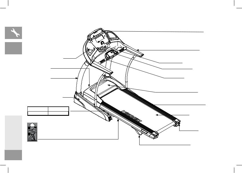
READING RACK 


CONSOLE 


WATER BOTTLE HOLDER
ON/OFF SWITCH
POWER CORD
CONSOLE MAST
CONSOLE MAST COVER
 CAUTION
  WARNUNG
KEEP HANDS AND FEET AWAY |
HALTEN SIE HÄNDE UND FÜSSE |
|
FROM THE MOVING PARTS. |
VON BEWEGLICHEN TEILEN FERN. |
|
|
|
|
|
|
|
1 |
2 |
FOOT LOCK LATCH (UNDERNEATH DECK)
SPEAKERS
HANDLEBARS
SAFETY KEY PLACEMENT
ACCESSORY TRAY
HEART RATE GRIP BARS
MOTOR COVER
SIDE RAIL
RUNNING BELT/DECK
REAR ROLLER
TENSION/ADJUSTMENT BOLTS
TRANSPORT WHEEL

TOOLS INCLUDED:
T-Wrench (included)
L-Wrench (included)
PARTS INCLUDED:
2 Console Masts
1 Console Assembly
2 Console Mast Covers
2 Handlebars
1 Hardware Kit
1 Safety Key
1 Power Cord
1 Audio Adapter Cable
1 Bottle of Silicone Lubricant (for 2 applications)
 NEED HELP?
If you have questions or if there are any missing parts, contact Customer Tech Support. Contact information is located on the back cover of this manual.
PRE ASSEMBLY
UNPACKING
Place the treadmill carton on a level flat surface. It is recommended that you place
a protective covering on your floor. Take CAUTION when handling and transporting ALL
this unit. Never open box when it is on its side. Once the banding straps have been removed, do not lift or transport this unit unless it is fully assembled and in the upright folded position, with the lock latch secure. Unpack and assemble the unit where it will be used. The enclosed treadmill is equipped with high-pressure shocks and may spring open if mishandled. Never grab hold of any portion of the incline frame and attempt to lift or move the treadmill.
MODELS
 WARNING
•DO NOT ATTEMPT TO LIFT THE TREADMILL! Do not move or lift treadmill from packaging until specified to do so in the assembly instructions. You may remove the plastic wrap from console masts.
•FAILURE TO FOLLOW THESE INSTRUCTIONS COULD RESULT IN INJURY!
 IMPORTANT NOTES
• During each assembly step, ensure that ALL nuts and bolts are in place and partially threaded. It is recommended you complete the full assembly of your unit before completely tightening any ONE bolt.
is recommended. |
ENGLISH |
• Several parts have been pre-lubricated to aid in assembly and usage. Please |
|
do not wipe this off. If you have difficulty, a light application of lithium bike grease |
|
5
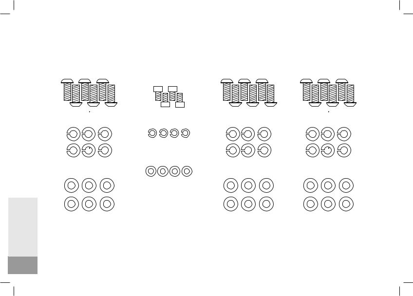
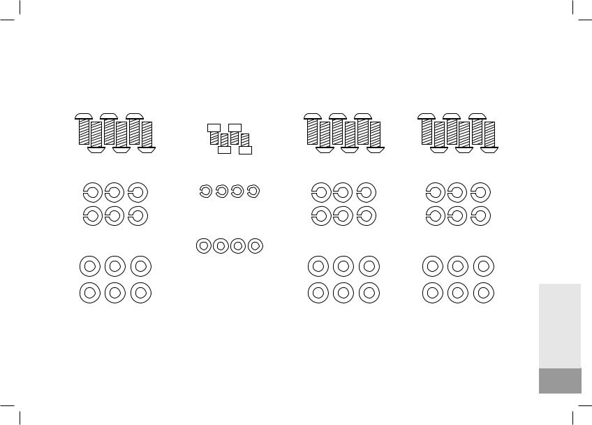
HARDWARE PACKAGE (T7.1)
|
STEP01 STEP02 |
STEP03 STEP04 |
STEP05 |
STEP09 |
|
Z01 Qty:6 |
Z04 Qty:4 |
Z09 Qty:6 |
Z01 Qty:6 |
Z05 Qty:4
Z02 Qty:6 |
Z08 Qty:6 |
Z02 Qty:6 |
Z06 Qty:4
Z03 Qty:6 |
Z07 Qty:6 |
Z03 Qty:6 |
ENGLISH
6

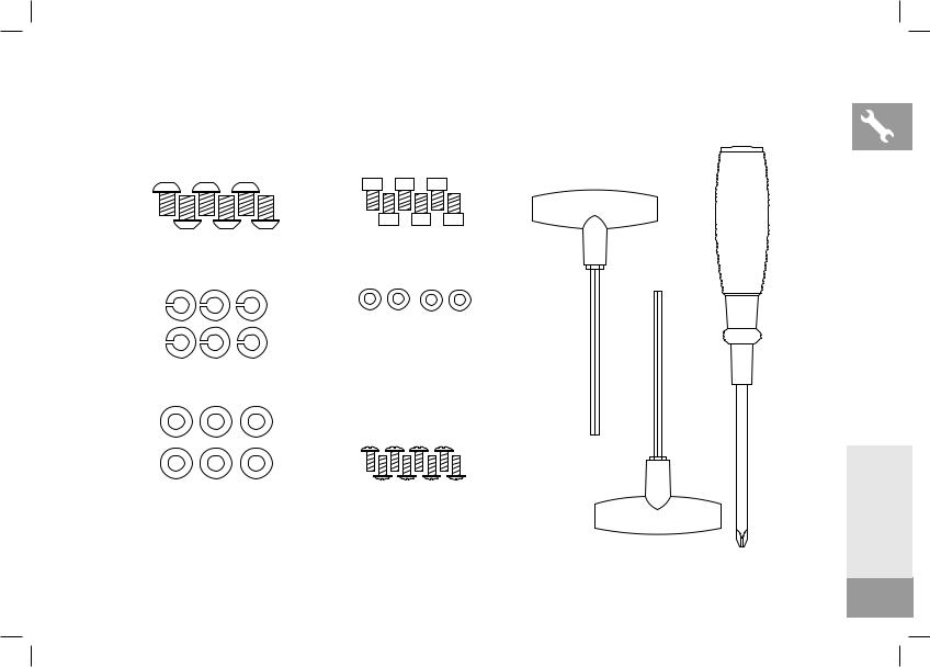
STEP10 |
STEP11 STEP12 |
#8X168L Qty:1 |
SCREWDRIVER Qty:1
Z10 Qty:6 |
Z13 Qty:6 |
Z12 Qty:4
Z08 Qty:6
STEP13
#6X167L Qty:1
Z07 Qty:6 |
Z11 Qty:8 |
|
#5x150L Qty:1
ENGLISH
7

HARDWARE PACKAGE (T5.1)
|
STEP01 STEP02 |
STEP03 STEP04 |
STEP05 |
STEP09 |
|
Z01 Qty:6 |
Z04 Qty:4 |
Z09 Qty:6 |
Z01 Qty:6 |
Z05 Qty:4
Z02 Qty:6 |
Z08 Qty:6 |
Z02 Qty:6 |
Z06 Qty:4
Z03 Qty:6 |
Z07 Qty:6 |
Z03 Qty:6 |
ENGLISH
8
STEP10 |
STEP11 STEP12 |
#5x150L Qty:1
SCREWDRIVER Qty:1
Z10 Qty:6 |
Z13 Qty:6 |
Z12 Qty:4
Z08 Qty:6
STEP13
Z07 Qty:6 |
Z11 Qty:8 |
#6X167L Qty:1 |
|
||
|
|
ENGLISH
9

ENGLISH
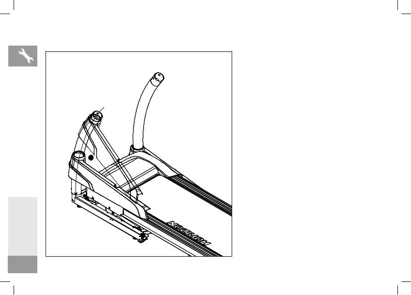
ASSEMBLY STEP 1
A Connect the CONSOLE CABLE from the RIGHT CONSOLE MAST and BASE FRAME
B Carefully slide the RIGHT CONSOLE MAST to the BASE FRAME, screw by 3 x hardware assembly (Z01+Z02+Z03)
A
B
A
Z01
Z02
Z03
10
ASSEMBLY STEP 2
A Carefully slide the LEFT CONSOLE MAST to the BASE FRAME, screw by 3 x hardware assembly (Z01+Z02+Z03)
A
Z01
Z02
Z03
ENGLISH
11
|
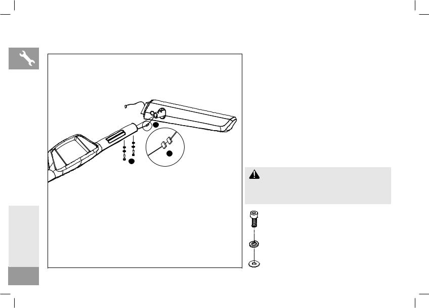
ASSEMBLY STEP 3 |
|
|
A Connect the HANDPULSE CABLE from RIGHT |
|
|
HANDLEBAR and HAND GRIP SET |
|
|
B Attach RIGHT HANDLEBAR to HAND GRIP |
|
|
SET then screw by 2x hardware assembly |
|
|
(Z04+Z05+Z06) |
|
|
A |
|
|
A |
|
|
B |
|
|
ATTENTION |
|
|
DO NOT PINCH THE WIRE !! |
|
|
Z04 |
|
ENGLISH |
Z05 |
|
Z06 |
||
|
||
12 |
|
ASSEMBLY STEP 4
A Connect the HANDPULSE CABLE from LEFT HANDLEBAR and HAND GRIP SET
B Attach LEFT HANDLEBAR to HAND GRIP SET then screw by 2x hardware assembly (Z04+Z05+Z06)
A
A
 ATTENTION
DO NOT PINCH THE WIRE !!
B
Z04
Z05
Z06
ENGLISH
13
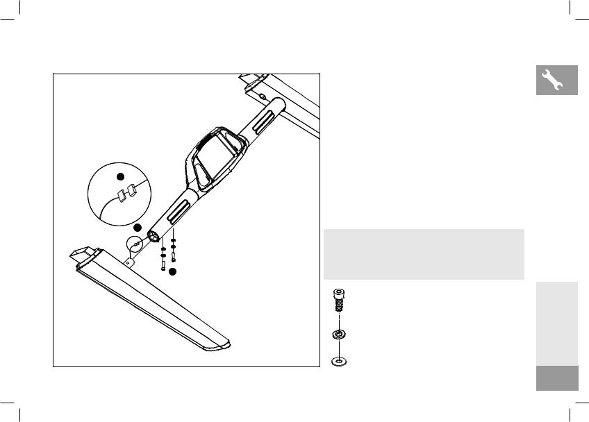
ASSEMBLY STEP 5 |
|
A Attach CONSOLE MAST SOCKET on the right |
|
|
|
|
|
side of CONSOLE SET by 3 x hardware assembly |
|
|
(Z07+Z08+Z09) |
|
|
B Attach CONSOLE MAST SOCKET on the left side |
|
|
of CONSOLE SET by 3 x hardware assembly |
|
|
(Z07+Z08+Z09) |
|
|
ATTENTION |
|
|
PLEASE TIGHTEN THE BOLTS BEFORE OPERATE THE |
|
|
NEXT STEP |
|
A |
|
|
|
Z07 |
B |
A |
Z08 |
|
|
|
ENGLISH |
|
Z09 |
|
|
|
14 |
|
|
ASSEMBLY STEP 6
A Slide RIGHT CONSOLE MAST COVER to RIGHT CONSOLE MAST carefully
A
ENGLISH
15
ASSEMBLY STEP 7
A Slide LEFT CONSOLE MAST COVER to LEFT CONSOLE MAST carefully
A 
ENGLISH
16
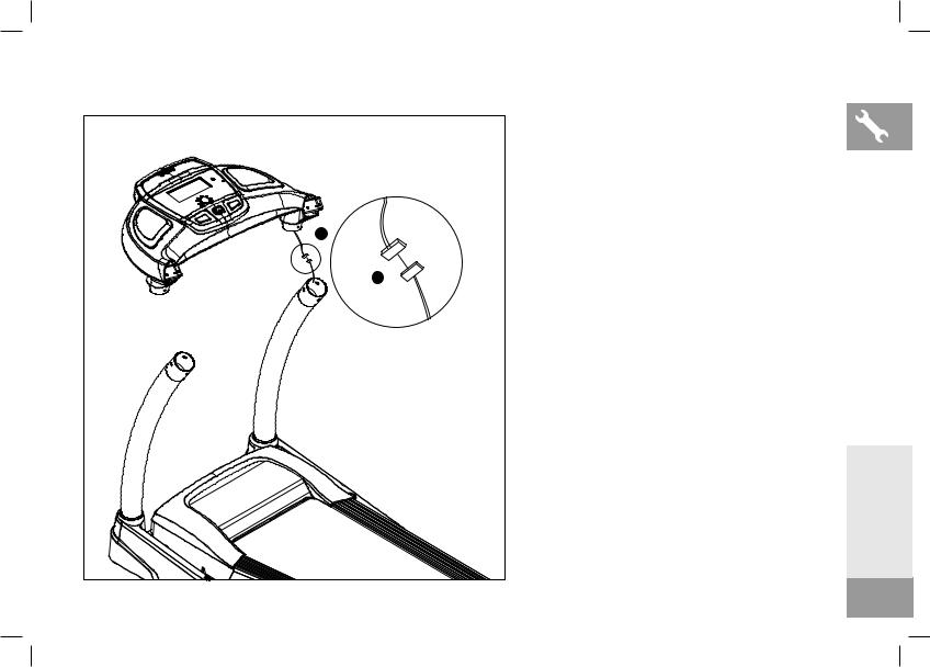
ASSEMBLY STEP 8
A Connect the CONSOLE CABLE from RIGHT CONSOLE MAST and CONSOLE SET
A
A
ENGLISH
17
|
ASSEMBLY STEP 9 |
|
|
A Attach CONSOLE SET to RIGHT CONSOLE MAST |
|
|
and LEFT CONSOLE MAST |
|
|
B Attach CONSOLE SET onto RIGHT CONSOLE MAST |
|
|
by 3x hardware assembly (Z01+Z02+Z03) |
|
|
C Repeat process B on the left side |
|
|
A |
|
|
A |
|
|
B |
|
|
C |
|
|
ATTENTION |
|
|
DO NOT PINCH THE WIRE !! |
|
|
Z01 |
|
ENGLISH |
Z02 |
|
Z03 |
||
|
||
18 |
|

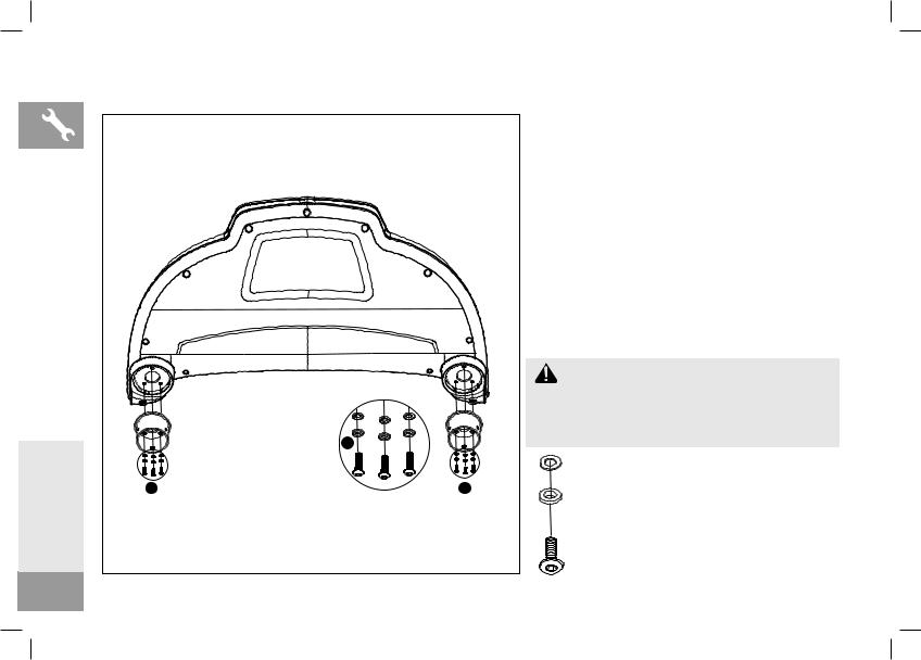
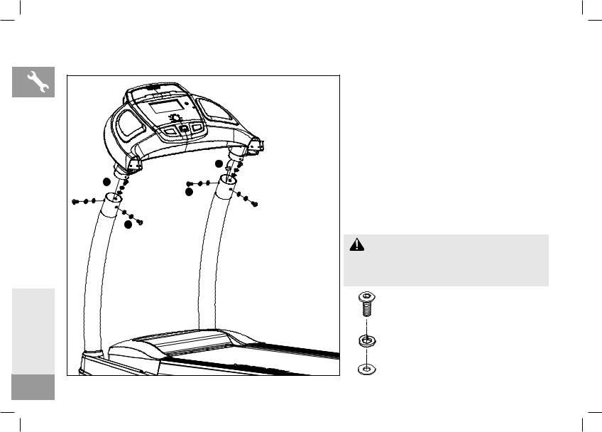
ASSEMBLY STEP 10 |
|
A Connect the both side of HANDPULSE CABLE to |
|
|
|
|
|
CONSOLE SET |
|
A |
B Attach HANDGRIP SET to CONSOLE SET and screw |
|
by 2x hardware assembly (Z07+Z08+Z010) from |
|
|
|
|
|
|
the right side and left side |
|
|
C Screw HANDGRIP SET onto CONSOLE SET by |
|
|
4x hardware assembly (Z07+Z08+Z10) from the |
A |
|
bottom of HANDGRIP SET |
B |
|
|
B |
|
|
C |
|
|
A |
|
|
|
|
ATTENTION |
C |
|
DO NOT PINCH THE WIRE !! |
|
|
Z07 |
|
|
Z08 |
|
|
Z10 |
ENGLISH
19
|
ASSEMBLY STEP 11 |
|
B |
|
A |
ENGLISH |
C |
|
|
20 |
|
AMove LEFT CONSOLE MAST COVER aside
BAttach the LEFT DROP DOWN HANDLEBAR to the
HANDGRIP SET and screw by 1 x blots (Z13)
CScrew the LEFT DROP DOWN HANDLEBAR to the
BASE FRAME by 2 x hardware assembly (Z13 + Z12)
Z13
Z12
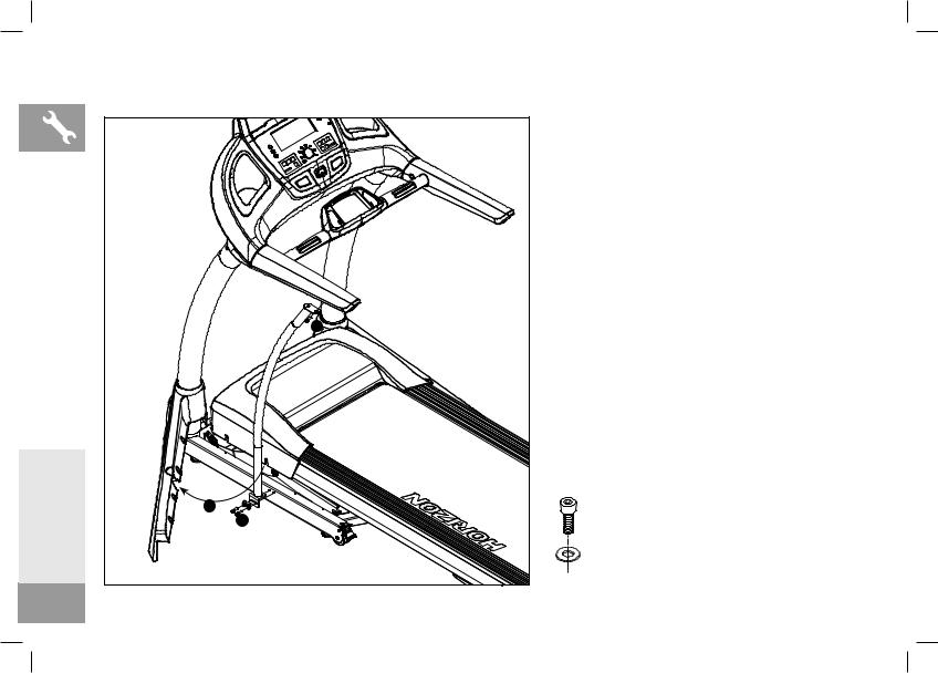
ASSEMBLY STEP 12
B |
C |
A |
AMove RIGHT CONSOLE MAST COVER aside
BAttach the RIGHT DROP DOWN HANDLEBAR to the HANDGRIP SET and screw by 1 x blots (Z13)
CScrew the RIGHT DROP DOWN HANDLEBAR to the BASE FRAME by 2 x hardware assembly (Z13 + Z12)
Z13
Z12
ENGLISH
21
|
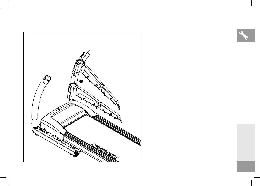
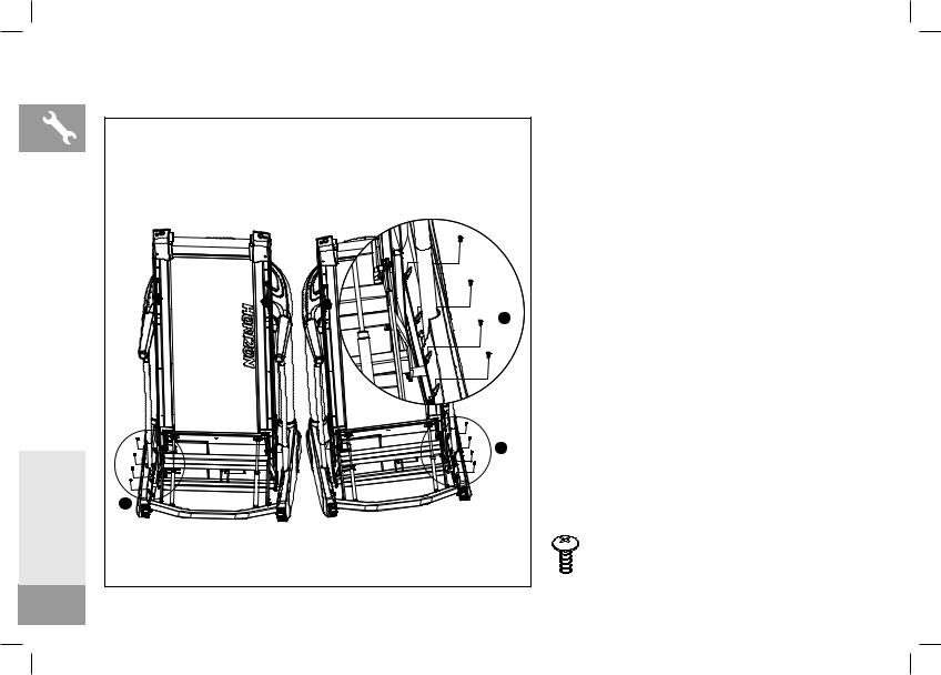
ASSEMBLY STEP 13 |
|
|
A Fold up the RUNNING DECK |
|
|
B Fasten the LEFT CONSOLE MAST COVER on BASE |
|
|
FRAME by 4 x SCREWS (Z11) |
|
|
C Fasten the RIGHT CONSOLE MAST COVER on |
|
|
BASE FRAME by 4 x SCREWS (Z11) |
|
|
B |
|
|
B |
|
ENGLISH |
C |
|
Z11 |
||
|
||
22 |
|
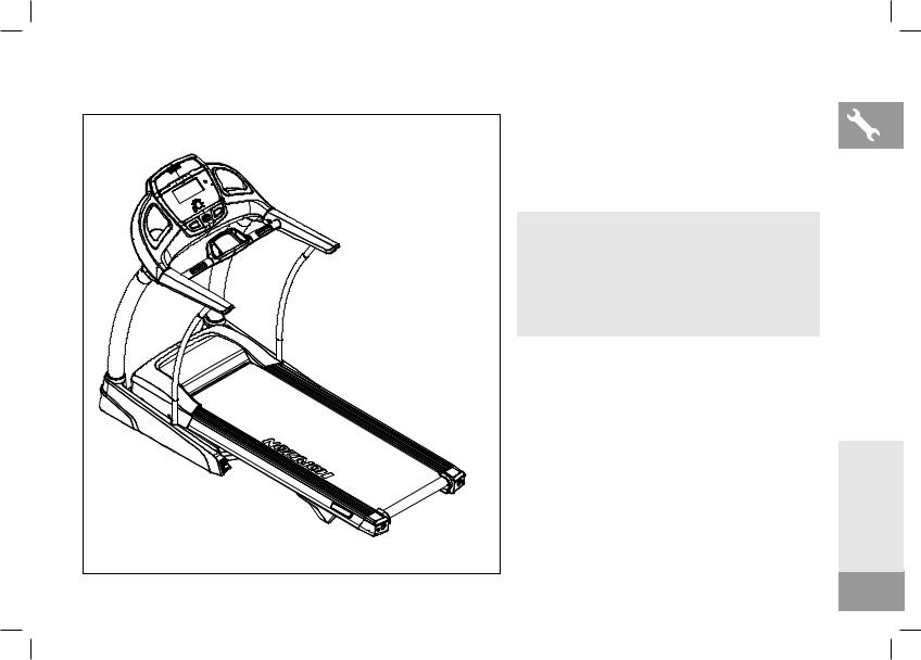
ASSEMBLY COMPLETE
BEFORE THE FIRST USE, FASTEN ALL THE
BOLTS AND LUBRICATE THE TREADMILL DECK
BY FOLLOWING THE INSTRUCTIONS IN THE
MAINTENANCE SECTION IN THE TREADMILL
GUIDE.
ENGLISH
23
 MONTAGE
 WARNUNG
Bei der Montage müssen einige Dinge ausdrücklich beachtet werden. Das korrekte Befolgen der Montageanleitung ist sehr wichtig, und es muss sichergestellt werden, dass alle Teile sicher befestigt wurden. Wenn die Montageanleitung nicht korrekt befolgt wird, sitzen Rahmenteile des Laufbands ggf. nicht fest, erscheinen lose und führen unter Umständen zu irritierenden Geräuschen. Zur Vermeidung von Beschädigungen des Laufbands müssen die Montageanleitung geprüft und Korrekturmaßnahmen ergriffen werden.
Suchen Sie vor dem Fortfahren nach der Seriennummer Ihres Laufbands am vorderen Stützrohr und geben Sie diese in das nachstehende Feld ein. Suchen Sie auch den Modellnamen, der sich neben der Seriennummer befindet.
GEBEN SIE IHRE SERIENNUMMER UND DEN MODELLNAMEN IN DIE NACHSTEHENDEN FELDER EIN:
SERIENNUMMER:
MODELLNAME: HORIZON FITNESS |
LAUFBAND |
DEUTSCH
24

LESEHALTERUNG
KONSOLE 


FLASCHENHALTER
EIN-/AUSSCHALTER
STROMKABEL
KONSOLENMAST
KONSOLENMAST-ABDECKUNG
 CAUTION
  WARNUNG
KEEP HANDS AND FEET AWAY |
HALTEN SIE HÄNDE UND FÜSSE |
|
FROM THE MOVING PARTS. |
VON BEWEGLICHEN TEILEN FERN. |
|
|
|
|
|
|
|
1 |
2 |
FUSSPEDALSPERRE (UNTER DECK)
LAUTSPRECHER
HANDGRIFFE
HALTERUNG SICHERHEITSSCHLÜSSEL
ABLAGEFACH
HERZFREQUENZ-GRIFFLEISTEN
MOTORABDECKUNG
SEITENSCHIENE
LAUFMATTE/LAUFDECK
HECKWALZE
SPANN-/EINSTELLSCHRAUBEN
TRANSPORTROLLE
T7.1
DEUTSCH
25

ALLE
MODELLE
DEUTSCH
MITGELIEFERTE WERKZEUGE:
T-Schraubenschlüssel
(im Lieferumfang enthalten) L-Schraubenschlüssel
(im Lieferumfang enthalten)
IM LIEFERUMFANG
ENTHALTENE TEILE:
2 Konsolenmaste
1 Konsolenaufbau
2 Konsolenmast-Abdeckungen
2 Handgriffe
1 Beschlagteilesatz
1 Sicherheitsschlüssel
1 Stromkabel
1 Audio-Adapterkabel
1 Flasche Silikonschmiermittel
(für 2 Anwendungen)
 BRAUCHEN SIE HILFE?
Wenden Sie sich bei Fragen oder fehlenden Teilen an den technischen Kunden-Support (Customer Tech Support). Die Kontaktdaten befinden sich auf der Rückseite dieser Bedienungsanleitung.
VOR DER MONTAGE
AUSPACKEN
Stellen Sie den Karton des Laufbands auf eine ebene Fläche. Es wird empfohlen, dass Sie eine Schutzfolie auf dem Boden auslegen. Gehen Sie bei Handhabung und Transport dieses Geräts VORSICHTIG vor. Öffnen Sie den Karton nicht, wenn dieser auf der Seite liegt. Sobald die Verpackungsbänder entfernt wurden, darf das Gerät nicht mehr angehoben oder transportiert werden, sofern es nicht vollständig montiert und in eine aufrechte, geklappte Position gebracht wurde, mit eingerasteter Laufdecksperre. Packen Sie das Gerät an dem Ort aus, an dem es verwendet werden soll, und montieren Sie es dort. Das Laufband ist mit Hochdruckstoßdämpfern ausgestattet, was dazu führen kann, dass es bei falscher Handhabung plötzlich aufklappen kann. Versuchen Sie niemals, das Laufband am Steigungsrahmen zu heben oder zu bewegen.
 WARNUNG
•DAS LAUFBAND NICHT ANHEBEN! Bewegen oder heben Sie das Laufband nicht aus der Verpackung, bis Sie hierzu angewiesen werden. Entfernen Sie die Plastikfolie von den Konsolenmasten.
•BEI NICHTBEACHTEN KANN ES ZU VERLETZUNGEN KOMMEN!
 WICHTIGE HINWEISE
•Stellen Sie während jedes Montageschritts sicher, dass ALLE Muttern und Schrauben eingesteckt und teilweise eingeschraubt sind. Es wird empfohlen, dass Sie zuerst eine Komplettmontage Ihres Geräts durchführen, bevor Sie IRGENDEINE Schraube voll anziehen.
•Mehrere Teile wurden zur Vereinfachung von Montage und Nutzung vorgeschmiert. Wischen Sie dieses Schmiermittel nicht ab. Wenn Probleme auftreten, wird das Auftragen von etwas Lithium-Fahrradfett empfohlen.
26
HARDWARE VERPACKUNG (T7.1)
SCHRITT01 SCHRITT02 |
SCHRITT03 SCHRITT04 |
SCHRITT05 |
SCHRITT09 |
|
|
Z01 Stck: 6 |
Z04 Stck: 4 |
Z09 Stck: 6 |
Z01 Stck: 6 |
Z05 Stck: 4
Z02 Stck: 6 |
Z08 Stck: 6 |
Z02 Stck: 6 |
Z06 Stck: 4
Z03 Stck: 6 |
Z07 Stck: 6 |
Z03 Stck: 6 |
DEUTSCH
27
 Loading...