


H-SERIES
FOR MODEL:
R3
B I K E USER’S GUIDE
|
|
|
H-Series_R3_Rev.1.6.indd 1 |
7/17/08 3:03:38 PM |
|
|
||
|
|
|

I N T R O D U C T I O N
CONGRATULATIONS and THANK YOU for your purchase of this Horizon Fitness bike!
Whether your goal is to win races or simply enjoy a fuller, healthier lifestyle, a Horizon Fitness bike can help you attain it – adding club-quality performance to your at-home workouts, with the ergonomics and innovative features you need to get stronger and healthier, faster. Because we're committed to designing fitness equipment from the inside out, we use only the highest quality components. It's a commitment we back with one of the strongest frame-to-brake warranty packages in the industry.
You want exercise equipment that offers the most comfort, the best reliability and the highest quality in its class.
Horizon Fitness delivers.
TABLE OF CONTENTS
Important Precautions |
4 |
|
|
|
|
|
|
Assembly |
5 |
|
|
|
|
|
|
Before You Begin |
13 |
|
|
|
|
|
|
Bike Operation |
14 |
|
|
|
|
|
|
Conditioning Guidelines |
25 |
|
|
|
|
|
|
Troubleshooting & Maintenance |
31 |
|
|
|
|
|
|
Limited Warranty |
35 |
|
|
CONTACT INFORMATION |
Back Panel |
|
|
|
|
|
|
|
|
|
|
IMPORTANT PRECAUTIONS INTRODUCTION
ASSEMBLY
BEFORE YOU BEGIN
BIKE OPERATION
LIMITED TROUBLESHOOTING CONDITIONING WARRANTY & MAINTENANCE GUIDELINES
H-Series_R3_Rev.1.6.indd 2-3 |
7/17/08 3:03:38 PM |
IMPORTANT INTRODUCTION PRECAUTIONS
ASSEMBLY
BEFORE BEGIN YOU
BIKE OPERATION
LIMITED TROUBLESHOOTING CONDITIONING WARRANTY MAINTENANCE & GUIDELINES
IMPORTANT PRECAUTIONS
SAVE THESE INSTRUCTIONS
Read all instructions before using this bike. When using an electrical product, basic precautions should always be followed, including the following: Read all instructions before using this bike. It is the responsibility of the owner to ensure that all users of this bike are adequately informed of all warnings and precautions. If you have any questions after reading this manual, contact Customer Tech Support at the number listed on the back panel of this manual.
To reduce the risk of burns, fire, electrical shock or injury to persons:
•If you experience chest pains, nausea, dizziness, or shortness of breath, stop exercising immediately and consult your physician before continuing.
•Maintain a comfortable pace.
•To maintain balance, it is recommended to keep a grip on the handlebars while exercising, mounting or dismounting the machine.
•Do not wear clothes that might catch on any part of the bike.
•Do not insert or drop any object into any opening.
•Unplug bike before moving or cleaning it. To clean, wipe surfaces down with soap and slightly damp cloth only; never use solvents. (See MAINTENANCE)
•This bike should not be used by persons weighing more than 300 pounds. Failure to comply will void the warranty.
•This bike is intended for in-home use only. Do not use this bike in any commercial, rental, school or institutional setting. Failure to comply will void the warranty.
•Do not use bike in any location that is not temperature controlled such as but not limited to: garages, porches, pool rooms, bathrooms, car ports or outdoors. Failure to comply may void the warranty.
•Use the bike only as described in this manual.
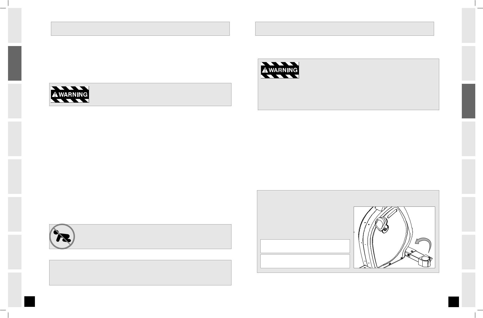
At NO time should pets or children under the age of 12 be closer to the bike than 10 feet. At NO time should children under the age of 12 use the bike.
Children over the age of 12 should not use the bike without adult supervision.
It is essential that your bike is used only indoors, in a climate controlled room. If your bike has been exposed to colder temperatures or high moisture climates, it is strongly recommended that the bike is warmed up to room temperature before first time use. Failure to do so may cause premature electronic failure.
ASSEMBLY
IMPORTANT: READ THESE SAFETY INSTRUCTIONS BEFORE USE!
There are several areas during the assembly process of a bike that special attention must be paid. It is very important to follow the assembly instructions correctly and to make sure all parts are firmly tightened. If the assembly instructions are not followed correctly, the bike could have frame parts that are not tightened and will seem loose and may cause irritating noises. To prevent damage to the bike, the assembly instructions must be reviewed and corrective actions should be taken.
UNPACKING
Unpack the product where you will be using it. Place the product on a level flat surface. It is recommended that you place a protective covering on your floor. During each assembly step, ensure that ALL nuts and bolts are in place and partially threaded in before completely tightening any ONE bolt.
Note: A light application of grease may aid in the installation of hardware. Any grease, such as lithium bike grease is recommended.
Before proceeding, find your bike’s serial number located on the front stabilizer tube and enter it in the space provided below. Also locate the model name which is located on the front plastics.
Enter your serial number and model name in the boxes below: 
SERIAL NUMBER:
MODEL NAME:
*Refer to the serial number and model name when calling for service.
*Also enter this serial number on your Warranty Card.
IMPORTANT PRECAUTIONS INTRODUCTION
ASSEMBLY
BEFORE YOU BEGIN
BIKE OPERATION
LIMITED TROUBLESHOOTING CONDITIONING WARRANTY & MAINTENANCE GUIDELINES
H-Series_R3_Rev.1.6.indd 4-5 |
7/17/08 3:03:41 PM |
IMPORTANT INTRODUCTION PRECAUTIONS
ASSEMBLY
BEFORE BEGIN YOU
BIKE OPERATION
LIMITED TROUBLESHOOTING CONDITIONING WARRANTY MAINTENANCE & GUIDELINES
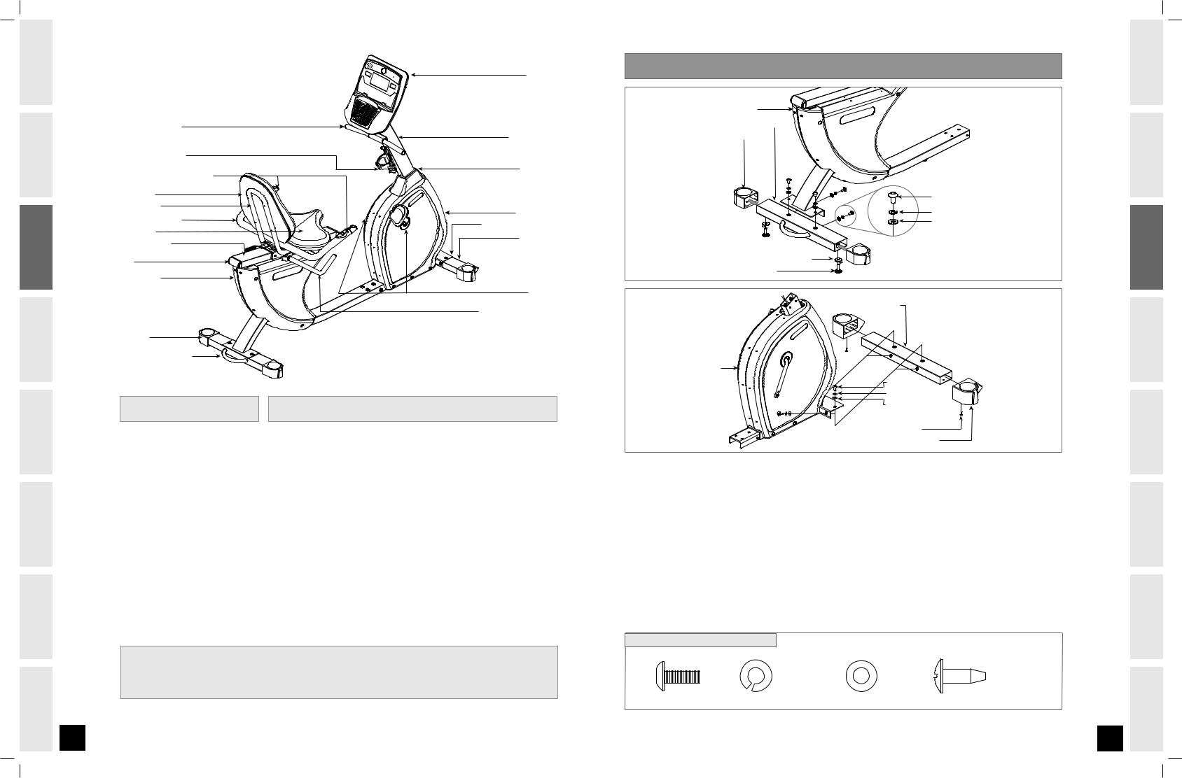
CONSOLE |
A S S E M B LY STEP 1 |
|
|
|
BASE FRAME |
|
UPPER HANDLEBAR |
|
REAR STABILIZER TUBE |
|
|
REAR END CAPS |
||
|
CONSOLE MAST |
||
|
|
||
WATER BOTTLE CAGE |
|
|
|
REMOTE RESISTANCE TOGGLES |
MAST BOOT |
|
|
|
|
||
SEAT BACK |
|
BOLT (A) |
|
SEAT FRAME |
MAIN FRAME |
SPRING WASHER (B) |
|
LOWER HANDLEBAR |
|||
FRONT STABILIZER TUBE |
FLAT WASHER (C) |
||
SEAT BASE |
FRONT CAP |
|
|
SEAT GUIDERAIL |
|
||
|
|
||
CAP |
|
LEVELER ADJUSTER |
|
|
LEVELER |
||
BASE FRAME |
|
||
|
|
||
|
PEDALS |
|
|
|
SEAT ADJUSTMENT LEVER |
FRONT STABILIZER TUBE |
|
|
|
END CAP |
|
|
|
|
|
REAR STABILIZER TUBE |
|
|
|
|
|
|
|
|
|
MAIN FRAME |
|
|
|
|
|
BOLT (A) |
|
|
|
|
|
SPRING WASHER (B) |
|
TOOLS INCLUDED |
PARTS INCLUDED |
|
|
WASHER (C) |
|
|
|
|
|||
|
|
|
|
SCREW (D) |
|
c Phillips Screwdriver |
c 1 Console |
c 1 Lower Handlebar |
|
FRONT END CAP |
|
c 4mm L Wrench |
c 1 Console Mast |
c 1 Upper Handlebar |
A |
Open HARDWARE BAG FOR STEP 1. |
|
c 5mm L Wrench |
c 1 Main Frame |
c 5 Hardware Bags |
|||
B |
Slide REAR END CAPS onto REAR STABILIZER TUBE. |
||||
c 5mm T Wrench |
c 1 Base Frame |
c 1 Rear Stabilizer |
|||
C |
Attach 2 LEVELERS and LEVELER ADJUSTERS (found in the hardware box) to the bottom of the REAR |
||||
c 13/15mm Flat Wrench |
c 1 Front Stabilizer Tube |
c 2 Front End Caps |
|||
|
STABILIZER TUBE and secure tightly. |
||||
|
c 2 Pedals with Straps |
c 2 Rear End Caps |
|
||
|
D |
Attach the REAR STABILIZER TUBE to the BASE FRAME using 4 BOLTS (A), 4 SPRING WASHERS (B) and 4 |
|||
|
c 1 Mast Boot |
c 2 Levelers and Adjusters |
|||
|
|
FLAT WASHERS (C). |
|||
|
c 1 Seat Back |
c 1 Audio Adaptor Cable |
E |
Slide FRONT END CAPS into FRONT STABILIZER TUBE with wheels facing forward and attach using 2 |
|
|
c 1 Seat Frame |
|
|
SCREWS (D) with provided Phillips screwdriver. |
|
|
c 1 Water Bottle Holder |
|
F |
Attach the FRONT STABILIZER TUBE to the MAIN FRAME using 4 BOLTS (A), 4 SPRING WASHERS (B) and 4 |
|
|
c 1 Seat Base |
|
|
FLAT WASHERS (C). |
|
|
|
|
|
HARDWARE BAG FOR STEP 1 CONTENTS :
If you have questions or if there are any missing parts, contact Customer Tech Support. If any warning decals become worn, damaged, or missing, they should be replaced.
Contact information is located on the back panel of this manual.
For a complete exploded diagram, visit us at www.horizonfitness.com
BOLT (A) |
SPRING WASHER (B) |
WASHER (C) |
SCREW (D) |
20 mm |
15.4 mm |
18 mm |
10 mm |
Qty: 8 |
Qty: 8 |
Qty: 8 |
Qty: 2 |
IMPORTANT PRECAUTIONS INTRODUCTION
ASSEMBLY
BEFORE YOU BEGIN
BIKE OPERATION
LIMITED TROUBLESHOOTING CONDITIONING WARRANTY & MAINTENANCE GUIDELINES
H-Series_R3_Rev.1.6.indd 6-7 |
7/17/08 3:03:51 PM |
IMPORTANT INTRODUCTION PRECAUTIONS
ASSEMBLY
BEFORE BEGIN YOU
BIKE OPERATION
LIMITED TROUBLESHOOTING CONDITIONING WARRANTY MAINTENANCE & GUIDELINES
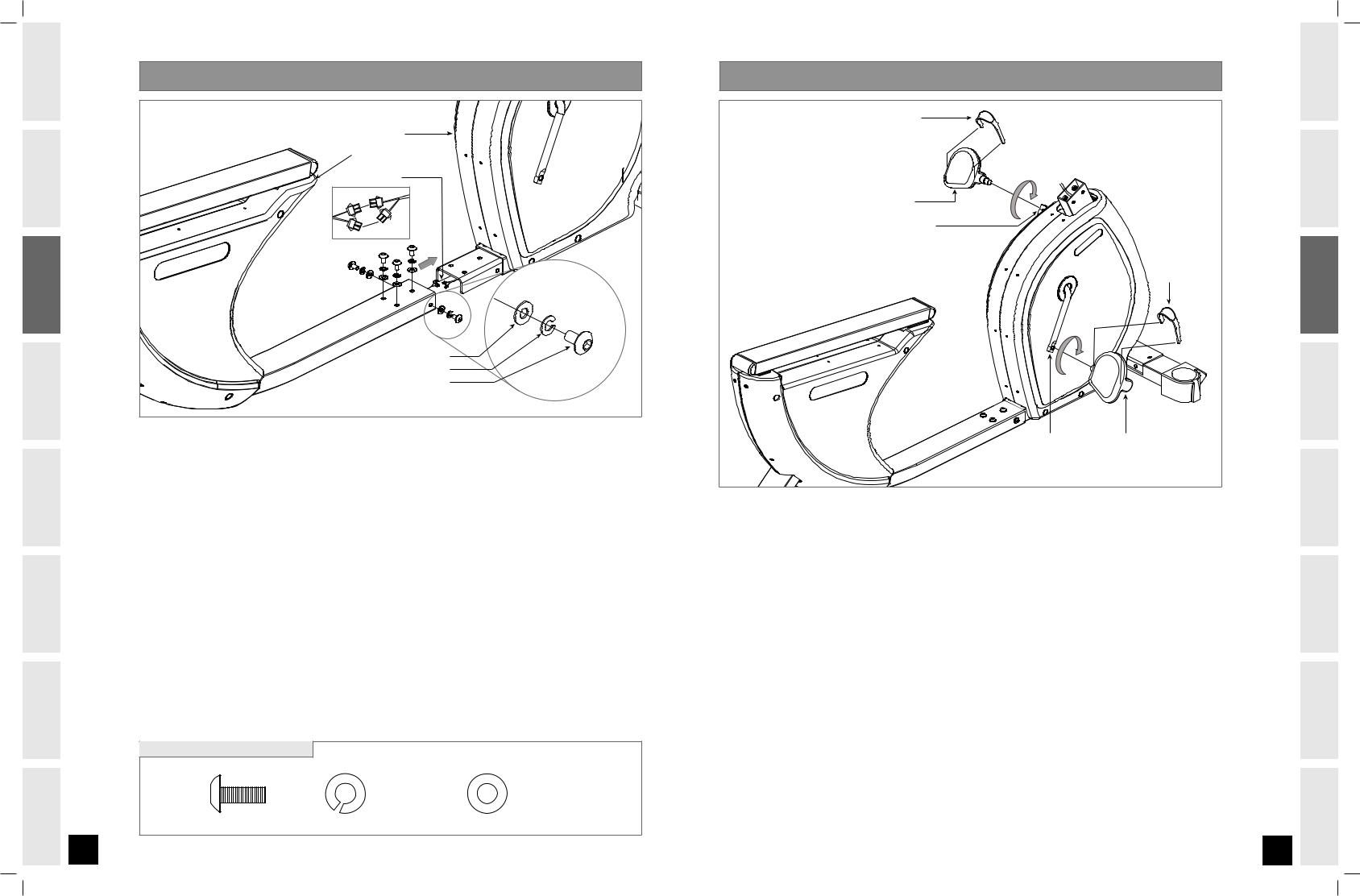
A S S E M B LY STEP 2 |
MAIN FRAME |
BASE FRAME |
CONNECT WIRES |
WASHER (C) |
SPRING WASHER (B) |
BOLT (A) |
AOpen HARDWARE BAG FOR STEP 2.
BConnect wires from BASE FRAME to MAIN FRAME.
CSlide MAIN FRAME into BASE FRAME.
DAttach the BASE FRAME to the MAIN FRAME using 5 BOLTS (A), 5 SPRING WASHERS (B) and 5 WASHERS (C).
DO NOT PINCH WIRES!
HARDWARE BAG FOR STEP 2 CONTENTS :
BOLT (A) |
SPRING WASHER (B) |
WASHER (C) |
20 mm |
15.4 mm |
18 mm |
Qty: 5 |
Qty: 5 |
Qty: 5 |
A S S E M B LY STEP 3 |
|
PEDAL STRAP |
|
LEFT PEDAL |
|
LEFT CRANK ARM |
|
|
PEDAL STRAP |
RIGHT CRANK ARM |
RIGHT PEDAL |
Note: There is no hardware bag for this step.
AAttach the Pedal STRAP to the PEDALS.
BAttach the Right Pedal onto the Right Crank Arm, tightening it clockwise with the provided
13mm/15mm Flat Wrench.
CAttach the Left Pedal onto the Left Crank Arm, tightening it Counter-Clockwise with the provided
13mm/15mm Flat Wrench.
Note: The Left Crank Arm is reverse threaded so it is very important that it is tightened Counter-Clockwise. Tightening it the opposite way can damage the pedal or the crank arm or both.
IMPORTANT PRECAUTIONS INTRODUCTION
ASSEMBLY
BEFORE YOU BEGIN
BIKE OPERATION
LIMITED TROUBLESHOOTING CONDITIONING WARRANTY & MAINTENANCE GUIDELINES
H-Series_R3_Rev.1.6.indd 8-9 |
7/17/08 3:04:01 PM |

IMPORTANT INTRODUCTION PRECAUTIONS
ASSEMBLY
BEFORE BEGIN YOU
BIKE OPERATION
LIMITED TROUBLESHOOTING CONDITIONING WARRANTY MAINTENANCE & GUIDELINES
10
A S S E M B LY STEP 4 |
|
|
STEP B |
STEP D |
|
|
SEAT FRAME |
SEAT LEVER |
SEAT BASE |
|
|
SEAT FRAME |
|
|
|
NOTE: Be sure to keep SEAT LEVER positioned upward as |
|
WAVY WASHERS (G) |
shown. Orientate SEAT LEVER CLAMP with rounded edge |
|
BOLTS (F) |
facing away from SEAT GUIDE RAIL as shown above. |
|
PRE-ATTACHED WASHERS |
SEAT GUIDE RAIL |
|
PRE-ATTACHED SPRING WASHERS |
|
|
PRE-ATTACHED BOLTS |
|
CAP |
|
|
|
SEAT GUIDE RAIL CAP |
|
|
|
|
BASE FRAME |
RUBBER STOPPER 


SCREW (H)
AOpen HARDWARE BAG FOR STEP 4.
BAttach the SEAT BASE to the SEAT FRAME using 4 BOLTS (F) and 4 WAVY WASHERS (G).
CRemove SEAT GUIDE RAIL CAPS, then remove the PRE-ATTACHED BOLTS, SPRING WASHERS and WASHERS from both ends of the SEAT GUIDE RAIL and lift from base frame. Note the orientation of the seat guide rail.
DSlide the SEAT FRAME through the rear of the SEAT GUIDE RAIL as shown above. Lock SEAT FRAME into place by pushing down on SEAT LEVER. NOTE: Seat lever will face forward when in locked position.
EAttach the RUBBER STOPPER to the bottom of the SEAT GUIDE RAIL using 1 SCREW (H).
FSet assembled SEAT GUIDE RAIL on the grooves of the BASE FRAME.
GRe-attach the PRE-ATTACHED BOLTS, SPRING WASHERS and WASHERS through the BASE FRAME into each end of the SEAT GUIDE RAIL. DO NOT TIGHTEN UNTIL ALL FOUR BOLTS HAVE BEEN STARTED.
HSnap SEAT GUIDE RAIL CAPS back onto each end of SEAT GUIDE RAIL.
HARDWARE BAG FOR STEP 4 CONTENTS :
BOLT (F) |
WAVY WASHER (G) |
SCREW (H) |
RUBBER STOPPER |
35 mm |
18 mm |
8 mm |
Qty: 1 |
Qty: 4 |
Qty: 4 |
Qty: 1 |
|
A S S E M B LY STEP 5 |
|
RECESS |
EXPOSED WIRES |
COVERED WIRE |
LOWER HANDLEBAR |
|
|
|
BOLTS (E) |
|
SPRING WASHERS (B) |
|
PULSE GRIP WIRES |
WIRE CLIP |
SEAT FRAME WIRES |
SEAT BACK 
WAVY WASHERS (G) 

BOLTS (F) 

A Open HARDWARE BAG FOR STEP 5.
BConnect the SEAT FRAME WIRES to the PULSE GRIP WIRES as shown above.
CPress COVERED WIRE into WIRE CLIP just before EXPOSED WIRES as shown above. Tuck EXPOSED WIRES under RECESS in LOWER HANDLEBAR.
DAttach the LOWER HANDLEBAR to the SEAT FRAME using 4 BOLTS (E) and 4 SPRING WASHERS (B). DO NOT PINCH WIRES!
EAttach the SEAT BACK to the SEAT FRAME using 4 BOLTS (F) and 4 WAVY WASHERS (G).
HARDWARE BAG FOR STEP 5 CONTENTS :
BOLT (E) |
SPRING WASHER (B) |
BOLT (F) |
WAVY WASHER (G) |
15 mm |
15.4 mm |
35 mm |
18 mm |
Qty: 4 |
Qty: 4 |
Qty: 4 |
Qty: 4 |
11
IMPORTANT PRECAUTIONS INTRODUCTION
ASSEMBLY
BEFORE YOU BEGIN
BIKE OPERATION
LIMITED TROUBLESHOOTING CONDITIONING WARRANTY & MAINTENANCE GUIDELINES
H-Series_R3_Rev.1.6.indd 10-11 |
7/17/08 3:04:13 PM |
 Loading...