

Honeywell TKL19, RTUL19 Installation Manual
TKL19
(RTUL19)
Tema1.0_L19_IM_1.0_EN Pagina 1 di 24
Installation Manual

CONTENTS
1.1 Wall Set Up for the Cable Trays.........................................................3
1.2 Electrical Connections........................................................................4
1.3 LONWORKS Data Cables................................................................6
1.4 Mounting the Wall Bracket..................................................................7
1.5 Cable Connections ............................................................................. 8
1.5.1
1.5.2
LON Cable.............................................................................. 8
Power Supply Cable +12VDC................................................9
1.5.3 Input Cable 1 – Door Contact............................................... 10
1.5.4
1.5.5
Input Cable 2 - Button ..........................................................11
Output Cable Relay 1- Door Open ....................................... 12
1.5.6 Output Cable Relay 2 – Signal Light .................................... 15
1.6 Mounting the Device on the Wall Bracket.........................................17
1.7 Identification Using the Service Pin..................................................18
1.8 Identification Using the Neuron ID....................................................19
2.1 TemaKey TKL19 (RTU-L19 code 1500154xx) ...................................20
2.1.1
2.1.2
Supplied Parts......................................................................21
Optional Parts....................................................................... 21
2.2 Recycling..........................................................................................22
Page 2 of 24
PPRREEPPAARRAATTIIOONNSS
11..11 WWaallll SSeett UUpp ffoorr tthhee CCaabbllee TTrraayyss
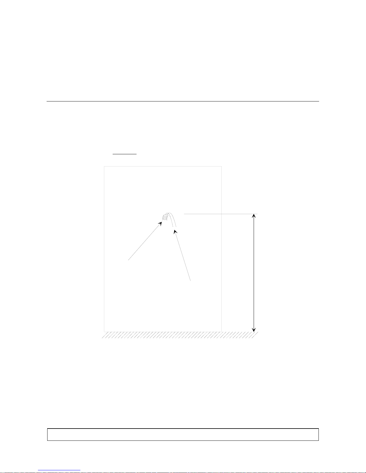
The cables must:
1) Protrude from the wall.
2) Come out at 120cm
cable tray
from ground (see Figure 1) (advised).
cables
m
c
0
2
1
Figure 1: Wall Set Up for the Cable Trays
Version: 1.0 E N
Floor
Page 3 of 24
11..22 EElleeccttrriiccaall CCoonnnneeccttiioonnss
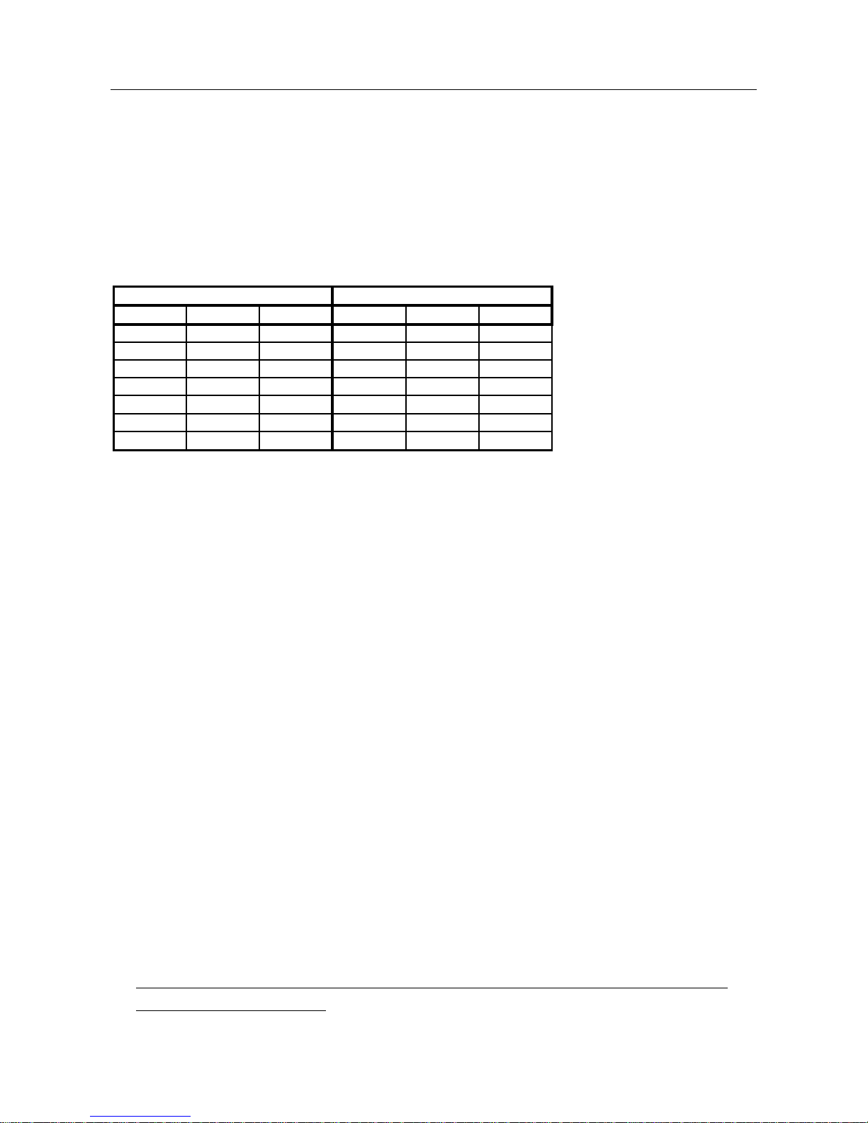
The RTU is powered at low voltage (12VDC 160mA), preferably using a
power supply module with battery backup (RTU-Qxx), or using an ordinary
power supply having the same characteristics. The power cables must be
dimensioned as indicated in the table below. The maximum allowable voltage
drop on the power cable is 1V.
• Cable length(m) = 1V / (I[A] load x 2 x (res [Ohm/km] /1000))
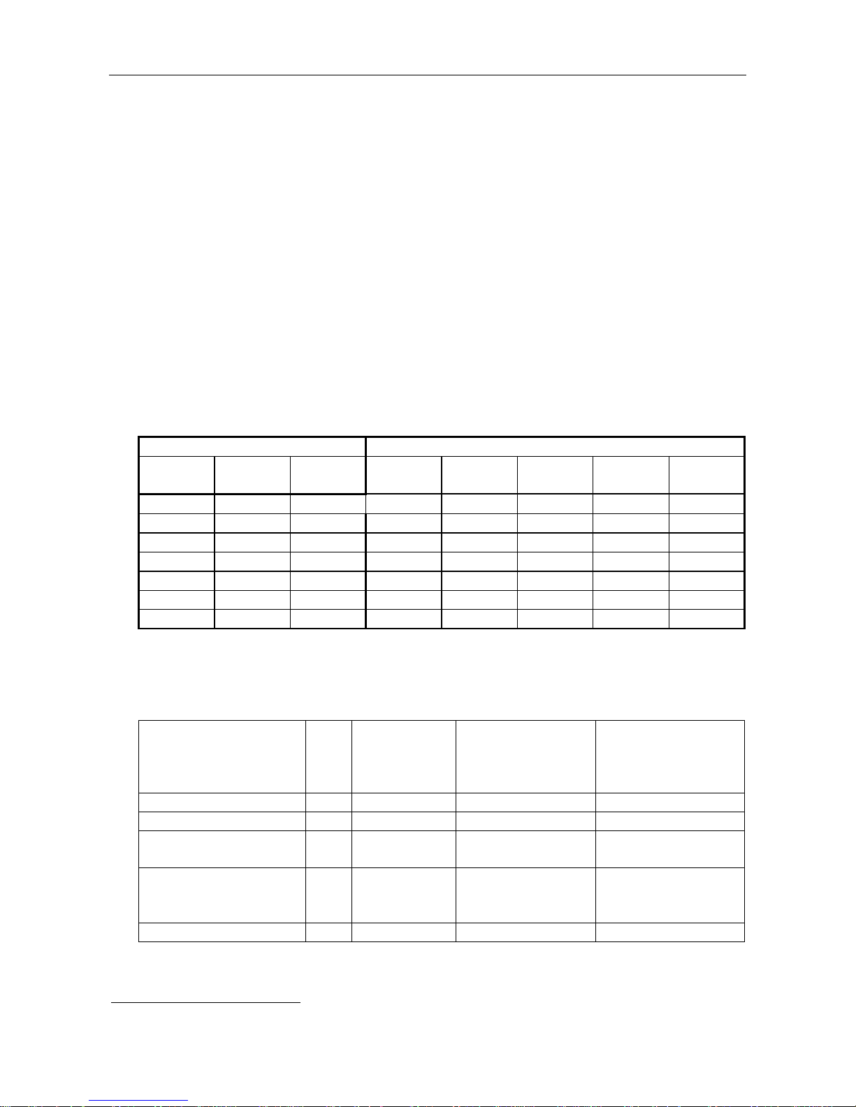
Cabl e Type
AWG mm2 ohm/ Km 160 [ mA] 320 [ mA]
12 3. 3 5. 7 548 274
14 2 8. 8 355 178
16 1. 3 14 223 112
18 0. 9 21 149 74
20 0. 6 34 92 46
22 0. 35 52 60 30
24 0. 2 85 37 18
Ext ensi on [ m] based on l oad
The device is equipped with 2 non-removable cables of 2m length:
•
Two-pole, twisted, unpolarized cable dedicated to the LON line
connection
2
- LON a 0,325 mm
LON b 0,325 mm
-
white
2
orange
• Ten-pole cable, providing the following signals:
2
- +12VDC 0,34 mm
- GND 0,34 mm
- INPUT 1 + 0,22 mm
- INPUT 2 + 0,22 mm
- RELAY 2 contact C 0,22 mm
- RELAY 2 contact NC 0,22 mm
- RELAY 2 contact NO 0,22 mm
- RELAY 1 contact C 0,56 mm
- RELAY 1 contact NC 0,56 mm
- RELAY 1 contact NO 0,56 mm
red
2
black
2
green / white
2
gray / green
2
brown
2
white
2
blue
2
green
2
yellow
2
gray
The signals must be connected using a shunt box with IP protection level
in conformance with the type of environment in which it is to be used:
- IP55 for moist environments
- Recessed box or IP31 at least for inside installations
The shunt box must be positioned within the perimeter controlled by the
access control system.
Page 4 of 24
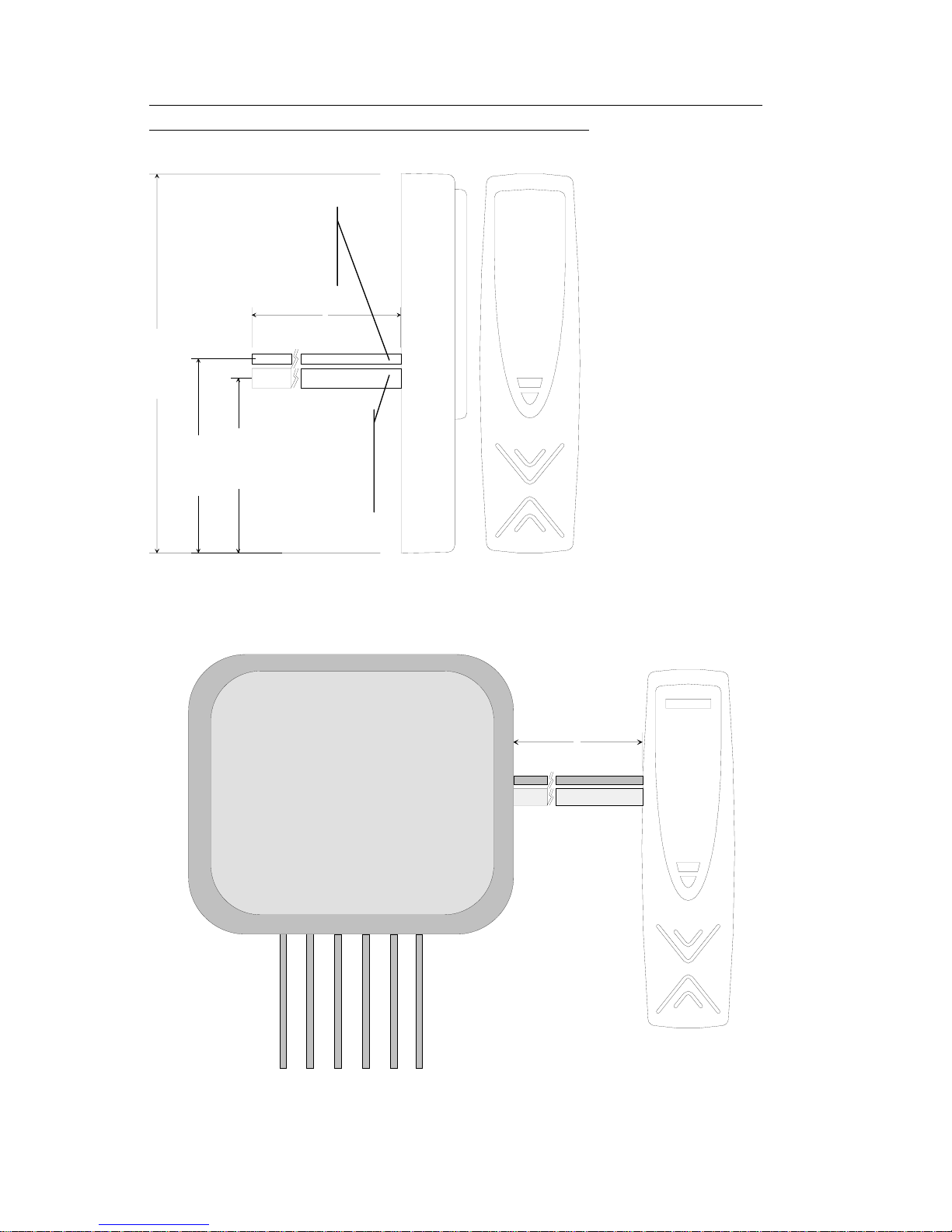
If necessary, the repeater relays must be inserted inside the box for
r
r
electrical locking commands and the signal light.
2-pole LON
cable
4 mm diamete
2 metri
6,10 cm
15,60 cm
7,20 cm
8,00 cm
10 pole
cable
8.6mm
diamete
Figure 2: Position and dimensions of the non-removable cables
2 meters
4,20 cm
Shunt Box
RTUL19
Cable +12VDC
Cable LON
Cable IN 1
Cable IN 2
Cable OUT 1
Cable OUT 2
Figure 3: Shunt Box
Page 5 of 24
N
L
W
11..33 L
OON
W
• The LONW
OORRKKS
S
ORKS
DDaattaa CCaabblleess
1
data cables must be double twisted-pair cables
• In a free topolo gy configuration, the overall length of the sections must not
exceed 500m
• In a bus configuration, the overall length of the sections must not exceed
2700m
• In the free topology configuration, the 50ohm terminator must be enabled
by inserting the appropriate jumper into the FTT10A plug-in on the CTUPLG06 board inside the TemaServer
• In a bus configuration, two terminators must be inserted at the two ends of
the bus (resistance of 100ohm 1% ½W)
• The L
ONWORKS
1
data cables must be dimensioned according to the
indications in Table 1
Cable Type Extension [m] based on cable capacitance
AWG mm2 Ohm/Km 50nF/Km 100nF/Km 200nF/Km 500nF/Km 1uF/Km
12 3.3 5.7 2676 1892 1338 846 598
14 2 8.8 2153 1523 1077 681 482
16 1.3 14 1707 1207 854 540 382
18 0.9 21 1394 986 697 441 312
20 0.6 34 1096 775 548 346 245
22 0.35 52 886 626 443 280 198
24 0.2 85 693 490 346 219 155
Table 1: Length/Capacitance of LONW
• The FTT10A Echelon
ORKS
v1.2 User’s Guide suggests using the cables as
1
Cables
indicated in Table 2.
Make and Model AW
G
Belden 85102 16 2700 500 500
Belden 8471 16 2700 400 500
Level IV (twisted pair,
solid, unshielded)
JY (St) 2x2x0,8 (4
solid wires, spiraltwisted, shielded)
TIA Cat5 / 900 250 450
22 1400 400 500
20 900 320 500
Bus
Connection
Max Length
total [m]
Free Topology
Connection Nodeto-Node Max
Length [m]
Free Topology -
Connection
Max Length total
[m]
Table 2: Suggested LONWORKS Cables
1
LONWORKS® is a trademark of the Echelon Corporation
Page 6 of 24
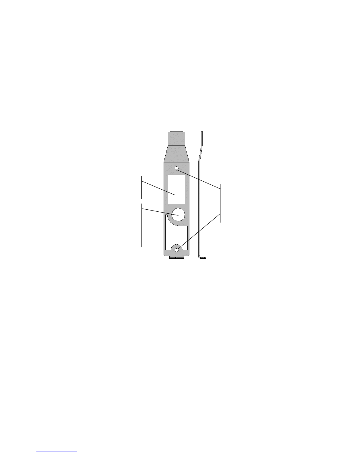
11..44 MMoouunnttiinngg tthhee WWaallll BBrraacckkeett
Mount the bracket onto the wall as follows:
1. Placing the brac ket against the wall to indicate the proper positions of the
holes, make the holes for the two bolts that will go into the wall to hold the
bracket (the bolts are included in the installation kit)
2. M ake sure that the cable tray bathces with the hole for the passage of the
cables
3. Screw in the bolts.
Hole for Cables
Holes for wall
mounting
Hole for inserting bolt and
screw to press against the
anti-removal/anti-open
tamper
Figure 4: Wall Bracket: Front View and Side View
Page 7 of 24
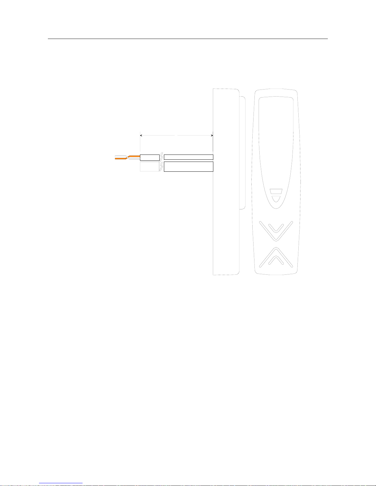
11..55 CCaabbllee CCoonnnneeccttiioonnss
1.5.1 LON Cable
LON A
LON B
Note: connection
not polarized
2 meters
6,10 cm
Figure 5: LON (1) Cable Connection
Page 8 of 24
 Loading...