

Honda CBR1100XX EFI Installation Manual

Motorcycle
Electronic Cruise Control
Installation Manual ©
For Honda CBR1100XX EFI
(Fuel injected models ONLY)
20 June 2005
MotorCycle Cruise Controls
MotorCycle Setup Pty. Ltd.
A.B.N. 94 798 167 654
6 Kingston Street
Mount Waverley, Victoria, 3149
AUSTRALIA
M
C
ycle
ruise
C
otor

Honda CBR1100XX EFI – all models ©
2
Electronic Cruise Control
Installation Manual ©
REFER TO THE INFORMATION, SET UP AND
OPERATION MANUAL FOR INFORMATION ABOUT
THE CRUISE CONTROL, SETTING UP, CALIBRATING
AND USING THE CRUISE CONTROL
The cruise control computer used has been purpose built for motorcycle applications. Testing has
resulted in programming to deliver safe, reliable operation on a variety of motorcycles, from 250cc up. It
is essential that you install the cruise control in accordance with the advice in the installation instructions
precisely so that electrical interference does not cause the unit to behave erratically or be rendered
inoperative.
We strongly recommend against fitting off-the-shelf motor car cruise controls to any motorcycle!
WARNING: - This cruise will function properly only if your vehicle has resistor type
(radio suppression) ignition wires (spark plug leads). The cruise control may not
function properly if aftermarket SOLID CORE spark plug wires are installed. Please
read Section 11, Safety Issues & Features before fitting & using the cruise control.
If, after reading these instructions, you feel you are not competent to install this kit, we strongly urge you
to seek the assistance of your local dealer.
NOTE: - It is recommended that on most motorcycles the fuel tank is less than 1/4 full before attempting
to fit the cruise control. The fuel tank must be lifted for most installation and can be very heavy
when full of fuel.
NOTE: - If the bike is fitted with a flasher device or LED brake light globe on the brake light system this
may cause interference with the cruise control brake detection. If the cruise control will not work try
disconnecting the flasher device or replacing the LED globe with a conventional globe. Contact us for
ways to enable both your brake light flasher or LED brake light and the cruise control.
CONTENTS
Chapters 1 to 5 and 8 to 11 are contained in the separate Information, Set up and Operation manual.
6. PREPARING THE BIKE FOR CRUISE CONTROL INSTALLATION
7. INSTALLATION
PARTS LIST (LAST PAGES)

Honda CBR1100XX EFI – all models ©
3
This manual contains several cautions, warnings and notes, which are prominently displayed. The convention
used is:
A warning applies whenever injury could result from ignoring the warning;
A caution applies whenever damage to the bike or cruise control could result from ignoring the caution; and
A note applies where other aspects should be considered before any action to do with installation is undertaken.
EXAMPLES:
WARNING: - Always ensure the bike is properly supported on the side or centre stand and cannot
accidentally fall off either stand.
CAUTION: - Before drilling any holes, make sure there are no components that may be damaged on the
other side of the surface being drilled. Double check for any wiring harness that might be easily
damaged by a drill bit.
NOTE: - Lay the wiring harness in place and connect the components before cable tying the harness in
place.
PARTS LIST
Check that all components depicted on the last pages of this manual are included in the cruise control kit.
Please phone (03) 9808 2804 within Australia, international (61 3) 9808 2804, fax (61 3) 9808 2445 or e-mail
mcsetup@bigpond.net.au for advice, if any parts are missing;
6. PREPARING THE BIKE FOR CRUISE CONTROL INSTALLATION
The following components will have to removed and operations performed.
• The seat;
• Disconnect the negative battery cable;
• The inner fairing panels around the instruments and the fuel tank;
• The fuel tank;
• The air filter housing.
• The opening or ‘pull’ throttle cable must be disconnected from the throttle bodies.
The following instructions may be followed to perform these operations.
The seat.
• Release the seat lock using the key. Pull the rear of the seat up and back to release the mounting tabs at the
front and middle of the seat.
Honda CBR1100XX EFI – all models ©
4
Disconnect the battery negative terminal.
• Loosen and remove the negative battery terminal bolt and disconnect the wire.
CAUTION: - Ensure that the wire is secured away from the battery terminal and cannot touch the
battery terminal accidentally.
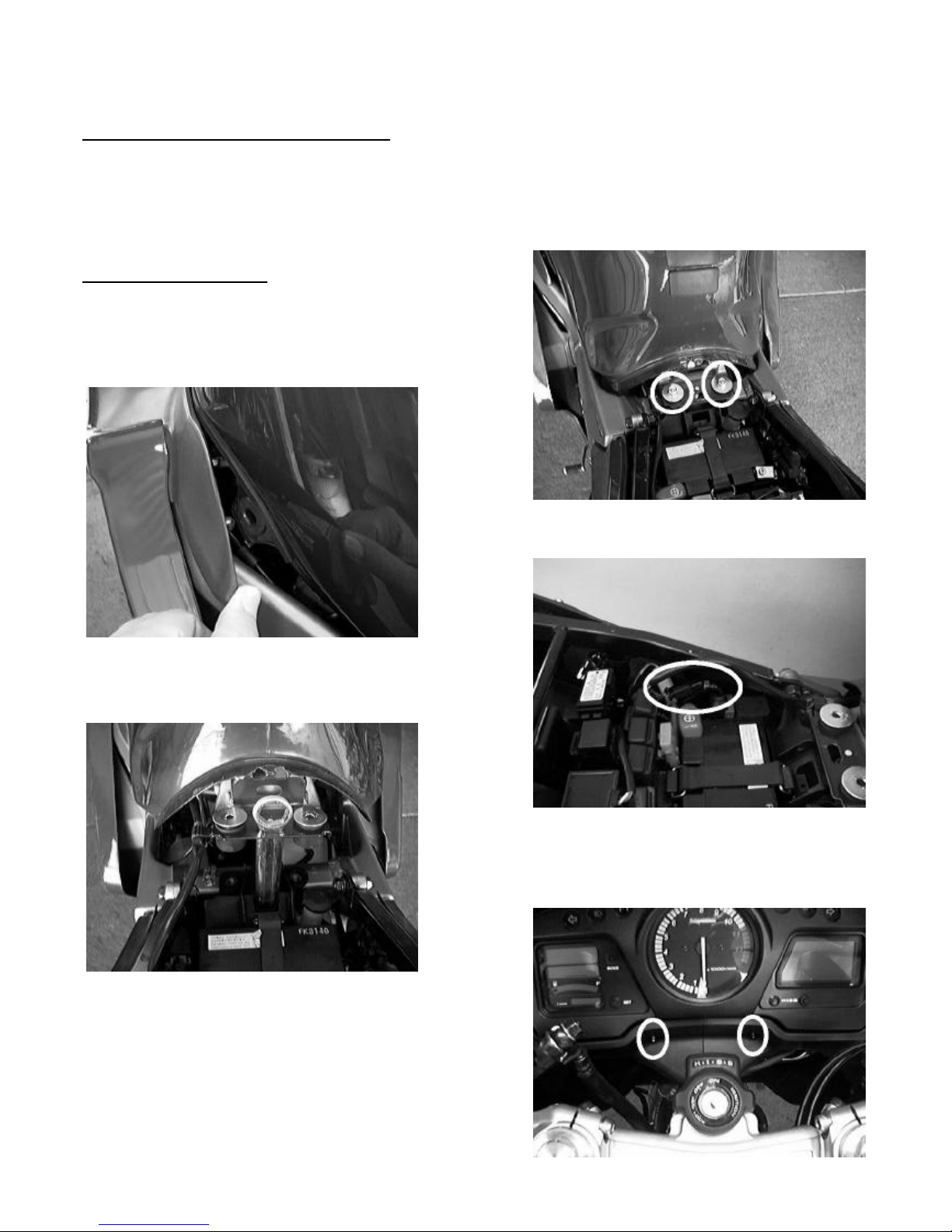
The inner fairing panels.
Raise the rear of the fuel tank as follows:
• Remove the two fuel tank mounting bolts at the rear of the
fuel tank.
• Release the inner panel bosses from the fuel tank on both
sides.
• Disconnect the fuel level sensor wire. It is a black three
or two pin (depends on model year) connector located
near the battery positive terminal.
• Lift the rear of the tank and support it using the bike’s rear
axle spanner (wrench) and extension handle. The handle
supports the tank and the spanner fits through the hole to
prevent the handle slipping out.
• Remove the instrument surround panels on both sides as
follows:
• Pull out the knob on the expansion clips below the
speedometer to release the clips (the clips will probably
NOT come out of the panel). Place the blade of a
screwdriver between the knob and the base of the clip and
gently twist the screwdriver to release the clip.
Honda CBR1100XX EFI – all models ©
5
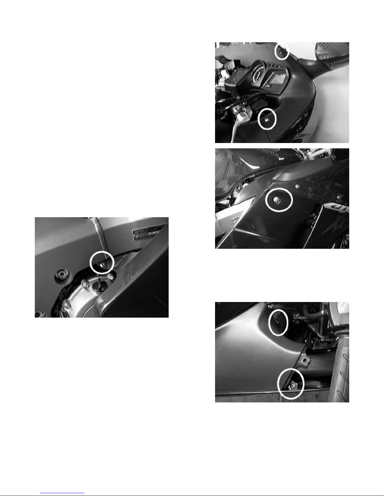
• Undo and remove the top screw and nut holding the
fairing screen on both sides.
• Undo the hex head screws at the rear edge of both panels.
• Lift out both panels. This can be a little awkward to do.
Pull the panel out at the top first, then manoeuvre the
panel out.
Remove the fuel tank surround panels as follows:
• Remove the large fairing bolts at the top rear of the fairing
side panels.
• Remove the small hex head screw attaching the inner part
of the fairing lower panel to the frame. The screw is
located just above the oil filler on the right side, and above
the clutch slave cylinder on the left side.
• Pull out the knob on the expansion clip that holds the
inner fairing panel to the frame. It is only necessary to
pull out the TOP clip of the pair on each side as the lower
clip is not for this panel (it is NOT necessary to take the
clip out completely. Just pull the knob out to release the
clip).
• Remove the expansion clip that holds the inner fairing
panel to the outer fairing panel.
• GENTLY manoeuvre the panel out. CAUTION: - there is a tab at the rear of the panel that is hooked over
the top rear fairing panel mounting boss (the one that you removed the large bolt from). Pull the rear edge
of the fairing lower outwards gently until you can unhook the tab and lift the inner panel clear
Honda CBR1100XX EFI – all models ©
6
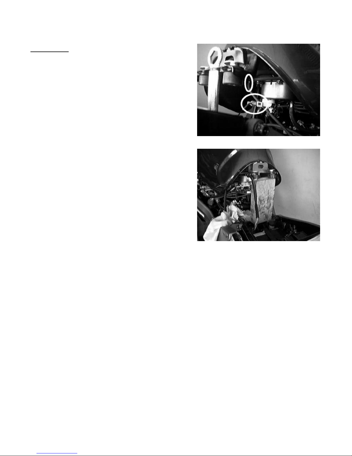
The fuel tank.
• Disconnect the fuel air vent tube. This is the smaller of
the two hoses attached directly to the bottom of the fuel
tank (NOT to the fuel pump base that is bolted into the
bottom of the fuel tank.
• Disconnect the fuel pump wires. This is a two pin brown
connector that is attached directly to the fuel pump base.
This connector has a latch that must be depressed to
release it. DO NOT PULL ON THE WIRES.
NOTE: - Supporting the rear of the fuel tank with the
bikes axle wrench is the method shown in the Honda
workshop manual. In practise, we found this did not
allow enough room under the fuel tank. We used a
piece of wood about 180mm (7”) long instead. We did
this AFTER disconnecting the air vent hose and the
fuel pump wires, as these were NOT long enough to
allow the tank to be held this high.
NOTE: - The following procedure will need to be carried out fairly quickly as fuel will be running out of
the fuel tank. Make sure that you pre-read the next few paragraphs, and have all the tools necessary
to perform the tasks.
WARNING: - There will be raw fuel and fuel vapours released during this operation.
Make sure that there are NO naked flames or sources of sparks present. Make sure
the work area is well ventilated.
CAUTION: - Make sure that the M12 x 25 (1.25mm pitch) bolt supplied in the cruise control kit is
ABSOLUTLEY CLEAN. You will be using this to plug the fuel injection hose, and there MUST be
NO dirt, dust or grease on it. Use some fuel or solvent to clean it BEFORE you begin working. If
there is ANY dirt on the fuel hose banjo fitting or nut on the end of the injector fuel rail, CLEAN it
carefully before going any further. Make sure that the area around the bottom of the fuel pump base
(the bottom of the fuel tank) is also clean.
CAUTION: - If any dirt or grit enters the fuel hose or fuel rail, it is possible that it may block a fuel
injector. The only way to fix this it to have the injectors cleaned or REPLACED. MAKE SURE
THAT EVERYTHING IS ABSOLUTLEY CLEAN.
Honda CBR1100XX EFI – all models ©
7
Things you will need to remove the fuel tank:
• A container that will hold about two cups of fuel that will fit under the rear of the fuel tank (you can lift the
rear of the tank to get it in there);
• A 12mm spanner for the service bolt;
• A 17mm spanner or socket for the main fuel tube sealing nut;
• A 19mm spanner for the bolt supplied in the kit to seal off the fuel hose;
• A 7~8mm (5/16”) drill bit (or something similar with a plain, not threaded, outside diameter) to block the
fuel return hose.
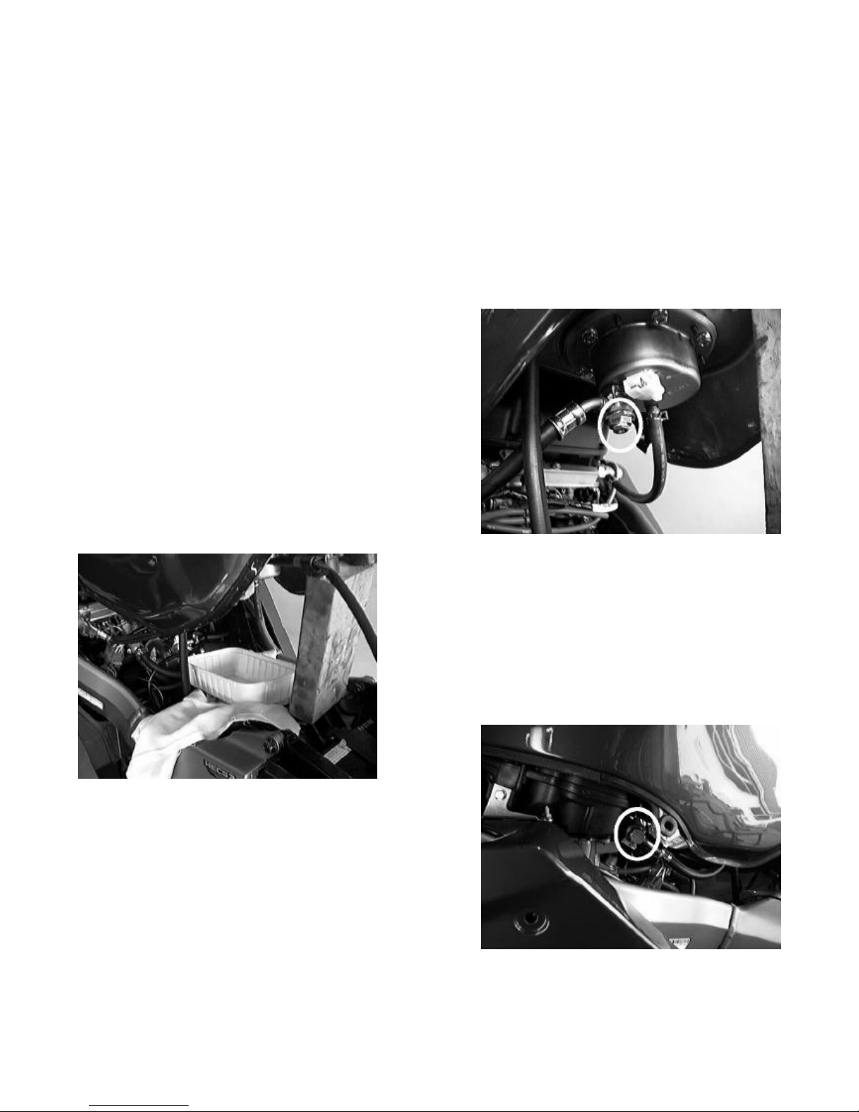
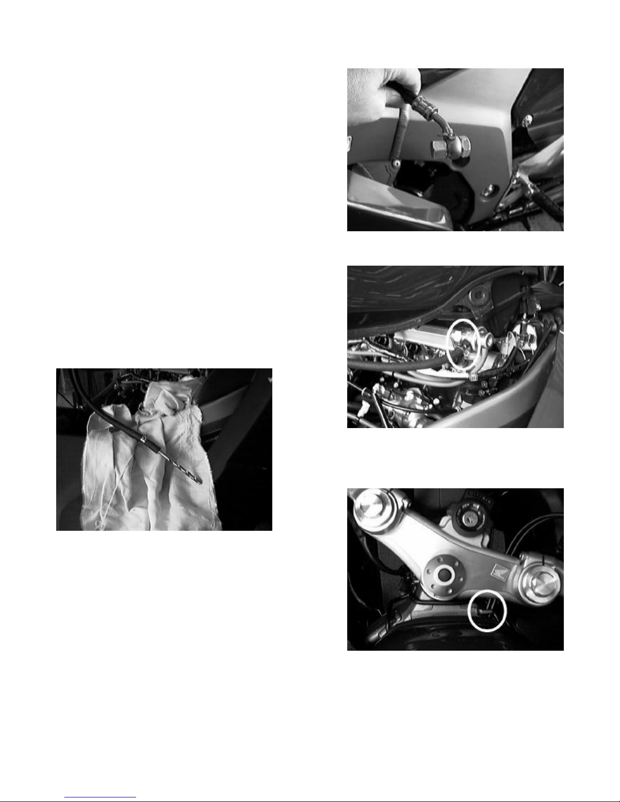
Release the fuel pressure as follows:
• Place a shop rag or towel under the rear of the fuel tank
under the service check bolt. The bolt is a small bolt in
the centre of the fuel banjo for the large hose that feeds
the fuel injector rail.
Note: - you may need to hold the large banjo bolt with a
spanner while undoing the small bolt.
• Slowly loosen the bolt using the rag to catch any spray of
fuel.
• Remove the service bolt and catch the fuel using a suitable
fuel container. Fuel will trickle out while the bolt is out.
• Loosen and remove the fuel injection rail fuel hosesealing nut and sealing washer, then remove the fuel hose
banjo and the second sealing washer.
Honda CBR1100XX EFI – all models ©
8
• Temporarily install the M12 x 25 (1.25mm pitch) bolt in
the fuel hose banjo, using the original washers and the
fuel tube sealing nut and tighten the nut.
• Re-install the small service bolt in the bottom of the fuel tank, using the original sealing washer.
• Disconnect the fuel return hose at the throttle body.
• Push the end of the drill bit into the hose to block it.
• Make sure that the throttle cables are hooked over the lug
on the frame at the front of the fuel tank. This will stop
the front tank mount snagging the cable when you lift the
tank off.
• Check that there are no other hoses or wires still connected, and lift the rear of the tank, then pull the tank
back to disengage the front mount.
• Lift the tank clear of the bike and place it carefully on the ground. Make sure that the hoses are not twisted
or kinked under the fuel tank.
Honda CBR1100XX EFI – all models ©
9
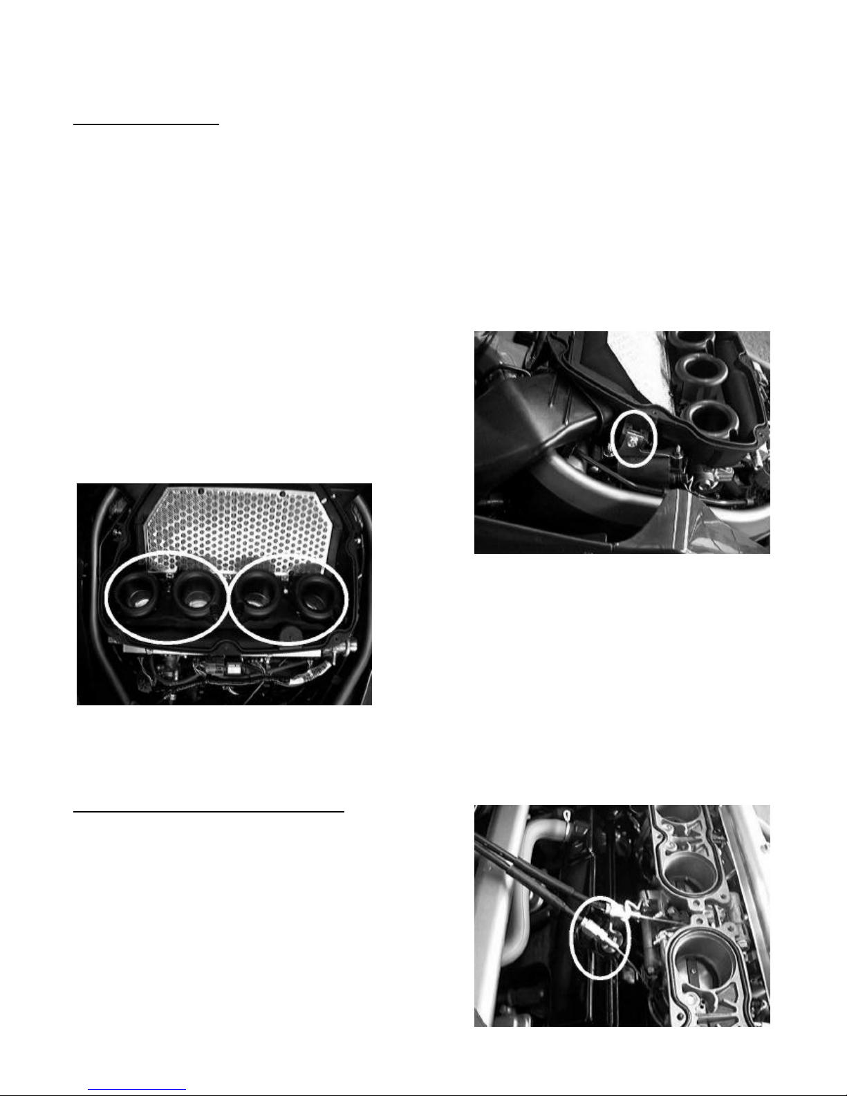
The air filter housing.
• Pull off the connector from the sensor on the top rear of the air filter cover. There is a latch on the
connector. DO NOT PULL ON THE WIRES.
• Remove the seven air filter cover screws and remove the cover.
CAUTION: - Be careful not to drop anything down the throttles. We recommend that you place a cloth
over the throats to prevent dirt entry and to catch any parts that might get dropped. Any parts that are
dropped will sit on the throttle butterflies (plates), but if they are operated any small parts will fall into
the cylinder head, or even into the cylinders. Recovering any lost parts would require a major engine
strip down.
• Remove the bolt holding the ignition coil bracket to the
sides of the air filter housing on both sides.
• Undo the screws holding the plastic venturis to the throttle
bodies.
• There are two hoses attached to the bottom of the air filter housing. One behind the right side ignition coil
and a second at the front, behind the steering head. Disconnect both of these hoses and remove the air filter
housing.
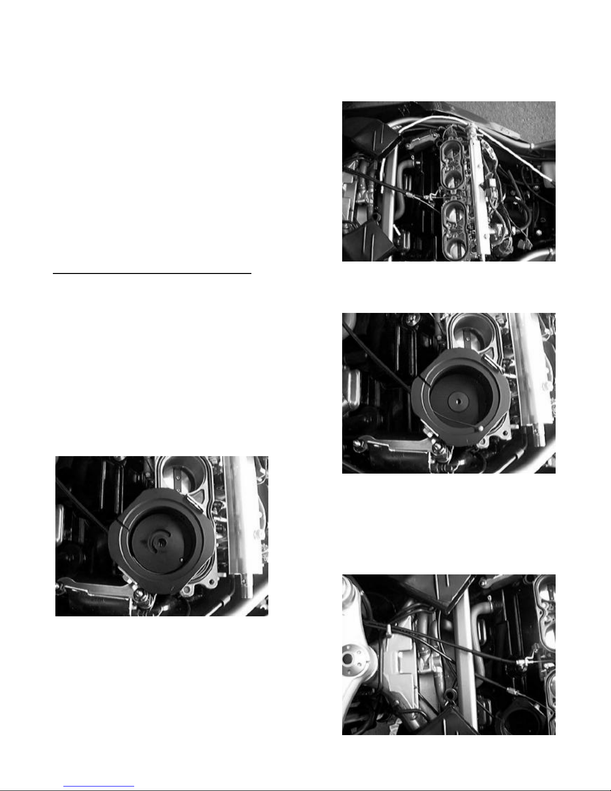
Disconnecting the opening throttle cable.
• Back off the adjusters in the throttle cable at BOTH ends
to give as much free play as possible.
• The opening (pull) throttle cable is the lower of the pair of
cables.
• Loosen the lock nuts and take the cable adjuster out of the
mount.

Honda CBR1100XX EFI – all models ©
10
• Take the nipple out of the throttle spindle spool and withdraw the cable.
• Screw BOTH lock nuts off the end of the adjuster then
screw them back onto the adjuster. This will repair the
flattened section of the threads on the adjuster.
• Screw the top nut all the way up the adjuster and tighten
it. Screw the second nut up to the first, BUT DO NOT
TIGHTEN IT.
NOTE: This is a good time to lubricate the throttle cable and the handgrip to ensure it operates freely.
THIS IS ESSENTIAL MAINTENANCE as the CIU and new ‘carburettor’ cable adds cable length
and increases friction on the throttle linkage. It is vital all cables are appropriately lubricated and
travel freely, otherwise the throttle may become stiff and heavy to use with the CIU installed. In the
worst case, the throttle spring may not return the engine to idle.
• Disassemble the throttle switch block assembly. There are two screws holding the two halves together.
They are accessible from under the switch block.
• Slowly apply 6 drops (only) of light sewing machine oil or equivalent (NEVER USE ENGINE OIL) to each
of the cable openings allowing the oil to run into the outer cable.
• Remove the throttle grip assembly from the handle bar.
• Clean the bar and inside the grip. Apply a little engine oil and spin the grip on the bar until it rotates freely.
• Reassemble the throttle grip and switch block assembly. Take care to locate the pin on the switch block in
the hole in the handlebar during re-assembly.
7. INSTALLATION
The main components to be installed include the vacuum actuator that controls the carburettor via the cable
interface unit, the wiring loom, the computer, the speed sensor and the switch. Installing components in the
following order has been found to be the most efficient.
Installing the vacuum actuator.
• The actuator attaches using fuel tank mounting bolts.
• Locate the bracket under the front edge of the battery box.
Lift the front of the battery box, place the bracket under it,
and then push the battery box back down into position.
The actuator should sit as shown with the cable running to
the right side of the bike.
Honda CBR1100XX EFI – all models ©
11
• If needed to hold the actuator in place, replace the two fuel tank mounting bolts as shown in the photo.
• Route the actuator cable forward around the right side of
the engine above the brake fluid lines, forward UNDER
the right side air filter snorkel but ABOVE the frame
cross tube, then across to the left side of the bike and
rearward and UNDER the frame cross tube that is above
the motor.
• The end of the cable should terminate below the left side
air filter snorkel.
Installing the CIU (Cable Interface Unit).
• Disassemble the CIU noting the location of the components. There is an exploded view of the CIU in the
parts list at the back of this manual.
• Loosen the locking screw in the side of the CIU.
• Insert the actuator cable into the unthreaded hole with the
lock screw until the cable bottoms on the shoulder and
gently tighten the locking screw.
• Ensure the inner cable is still free by pushing and pulling
the cable end.
• Insert the ball nipple in the actuator cable into the hole in
the thin actuator spool.
• Place the spool in the CIU with the groove side up and
rotate the spool anti-clockwise to fully extend the cable.
• Route the original throttle cable UNDER the frame cross
tube as shown.
• Make sure that the cable is ABOVE the cruise control
actuator cable.
Honda CBR1100XX EFI – all models ©
12
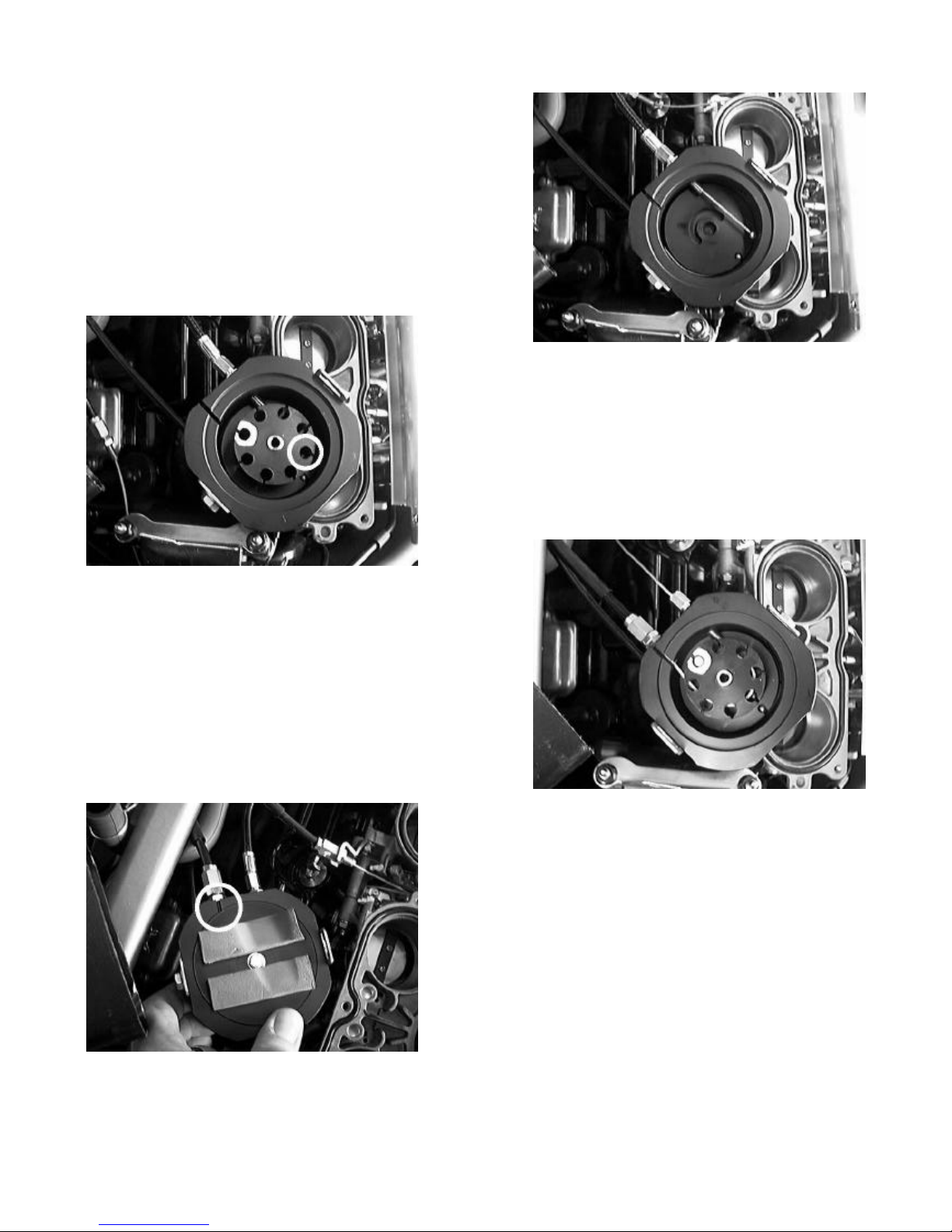
• Locate the new ‘carburettor’ cable in the kit. Screw the
ball nipple end of the cable into the threaded, un-slotted
hole in the CIU.
• Place the ball nipple on the ‘carburettor’ cable in the
marked hole on the BACK (roll pin side) of the dual
spool.
• Position the spool in the CIU so that the roll pin engages
in the groove in the actuator spool.
• Insert the bush into the two spools.
• Insert the nipple on the original throttle cable into the
marked hole in the TOP of the CIU.
• Screw the adjuster all the way into the slotted hole in the
CIU.
• Place the end cap on the CIU.
• Place a flat washer on the pivot bolt and insert the bolt
into the CIU from the top. Place another flat washer and
the Nyloc nut on the bottom of the CIU.
• Rotate the cap so that the gap in the foam pads runs across
between the mounting tabs. Tighten the nut GENTLY.
• Fill the slot with a silicone sealant to prevent dirt or water
entry.
 Loading...