

Hobart UX-30 EH, UX-30 ESH, UX-30 EB, UX-30 E, UX-30 ES Installation And Operating Instructions Manual
...Page 1
Utensil Washing Machine
UX-30 EH / UX-30 ESH
INSTALLATION OPERATION
VERSION 23/11/99
Page 2

Installation and Operation Instructions
for HOBART Utensil Washing Machine
Model UX-30 EH / UX-30 ESH
Content Page
1 Installation............................................................................................. 3
2 Connections .......................................................................................... 3
3 Controls................................................................................................. 6
4 First run................................................................................................. 7
5 Adjustment of detergent concentration ................................................. 8
6 Adjustment of rinse agent concentration............................................... 8
7 Softener ................................................................................................ 9
8 Operation ............................................................................................ 10
9 Cleaning the machine ......................................................................... 11
10 Frost prevention .................................................................................. 12
11 Maintenance ....................................................................................... 12
12 Trouble shooting.................................................................................. 13
Machine noise level is ≤ 70 dB (A)
Important Notes
● Use in Accordance with Regulations
Hobart Utensil Washing Machines are only intended for cleaning pots
and pans, baking sheets, cutlery, trays etc.
Do not use for electrically heated cooking and heat conservation
appliances.
● Safety
Never hose down the machine.
The "Attention" symbol is shown beside instructions that are essential
for the safe operation of the machine. Please read these passages
very thoroughly.
● Liability
Installations and repairs which are not carried out by authorized
technicians or the use of other than original spare parts, and any
technical alterations to the machine, may affect the warranty
set out in the standard conditions of sale.
2
Page 3
1 Installation
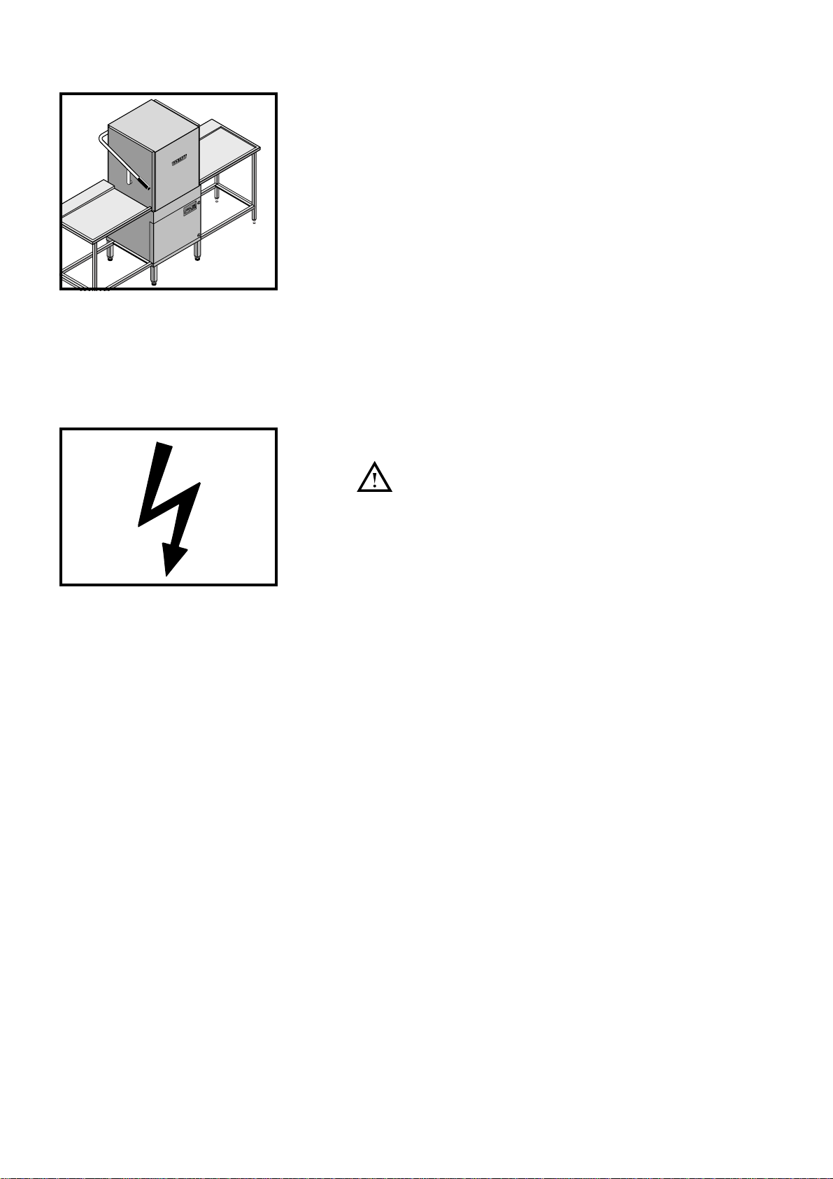
1.1 Location
– Wall clearance of 150 mm is required.
– Level machine by turning the feet.
– Distribute machine weight equally onto all feet.
0
9
¡C
5
8
0
0
8
7
5
5
6
7
0
0
6
7
0
5
5
6
5
0
0
6
5
5
4
0
4
2 Connections
2.1 Electrical connection
Must be carried out by an authorized technician
according to the national and local codes.
– The appliance is intended for a fixed electrical connection.
Main-switch is required according EN 60 204.
– Check machine specifications to make sure they correspond to
those of the site supply and to wiring diagram.
– Check site fuse rating.
According to EN 60 335 the appliance must be connected to an
equipotential conductor. The connecting screw is located beside
the cable inlet.
3
Page 4

2.2 Water connection
Must be carried out by an authorized technician
according to the national and local codes.
The machine must be operated with water of drinking quality.
For water with an extremely high mineral content, water
treatment is recommended.
Machines without Softener:
(U.K. only: this machines are fitted with Class "A" Air Gap.)
– Connection if possible to soft (4° Clark) and warm (max. 60°C)
water.
– Line flow pressure 0.4 – 6 bar.
If line flow pressure is below 0.4 bar: provide rinse booster
pump at site.
Machines with Softener (S-models only):
For U.K. see separate infor mation*.
– Connection if possible to warm water (max. 60°C).
– Line flow pressure 1.5 – 6 bar.
If line flow pressure is below 1.5 bar: provide rinse booster
pump at site.
If line flow pressure is above 6 bar: provide a pressure
reducing valve.
– Connect flexible supply hose with union nut 3/4" to site
connection.
– Fit shut-off valve.
* U.K. only: Machines with softener
All United Kingdom installations must be supplied from
storage not mains. Direct connections to the mains supply
contravenes Water Authority regulations.
– Connection if possible to warm water.
The supply water temperature into the machine should not
exceed 60°C.
For temperatures in excess of 60°C, a thermostatic mixing valve
should be fitted at installation.
This valve is available from HOBART Service Centres.
– Fit shut-off valve.
Low Pressure Situations
Below 0.4 bar (6 psi) flow pressure there are two solutions.
a) Provide a suitable water storage tank at a height which will
create a pressure in excess of 0.4 bar or,
b) fit a water pump to increase the pressure.
A suitable pump can be supplied by HOBART at extra cost.
Medium Pressure Situations
0.4 - 0.7 bar (6-10 psi) flow pressure.
Most installations will fall into this category and the machine will
arrive fitted with a solenoid valve designed for this pressure range.
High Pressure Situations
Above 0.7 bar flow pressure.
a) Fit a water storage tank at a suitable height.
b) Fit a pressure reducing valve during installation.
4
Page 5
2.3 Hot water connection
(hot-water heated machines only)
Must be carried out by an authorized technician
according to the national and local codes.
– Connection to hot water supply (DN 20) on customer site
PN 25 (110°C - 200°C). See data plate !
– The machine is equipped with all necessary fittings.
– Dimension of hot water flow and return piping has to be
according to the requirements.
– Make sure that permissible pressures and temperatures will not
be exceeded.
– All pipework has to be insulated with water and heat resistant
material.
2.4 Steam connection
(steam heated machines only)
Must be carried out by an authorized technician
according to the national and local codes.
– Connection to steam supply (DN 20) at customer site
0.3 - 3.5 bar (max. 150°C) or 3.5 - 10 bar (max. 200°C).
See data plate !
– Dimension of steam and condensate piping has to be according
to the requirements.
– The machine is equipped with all necessary fittings.
– Make sure that permissible pressures and temperatures will not
be exceeded.
– All pipework has to be insulated with water and heat resistant
material.
A
2.5 Adjustment of shut-off valve with flow reducer for
steam and hot water supply
– The built-in shut-off valve is equipped with an adjustment device
(A) to limit the heating supply medium.
A special tool is necessary for adjusting the valve-seat.
– The correct adjustment is very important particulary for higher
pressure, and therefore must be done by a HOBART trained
service man at first installation or after any changes are done
at the customer site.
– The adjustment is correct if the heating-up time of the boiler is
as long as the shortest wash cycle, while the valve is opened to
maximum.
– If adjusted too far open pressure shocks may occur when the
solenoid valve closes. This could cause damage at the installation.
If adjusted too far close the required heating-power cannot be
achieved.
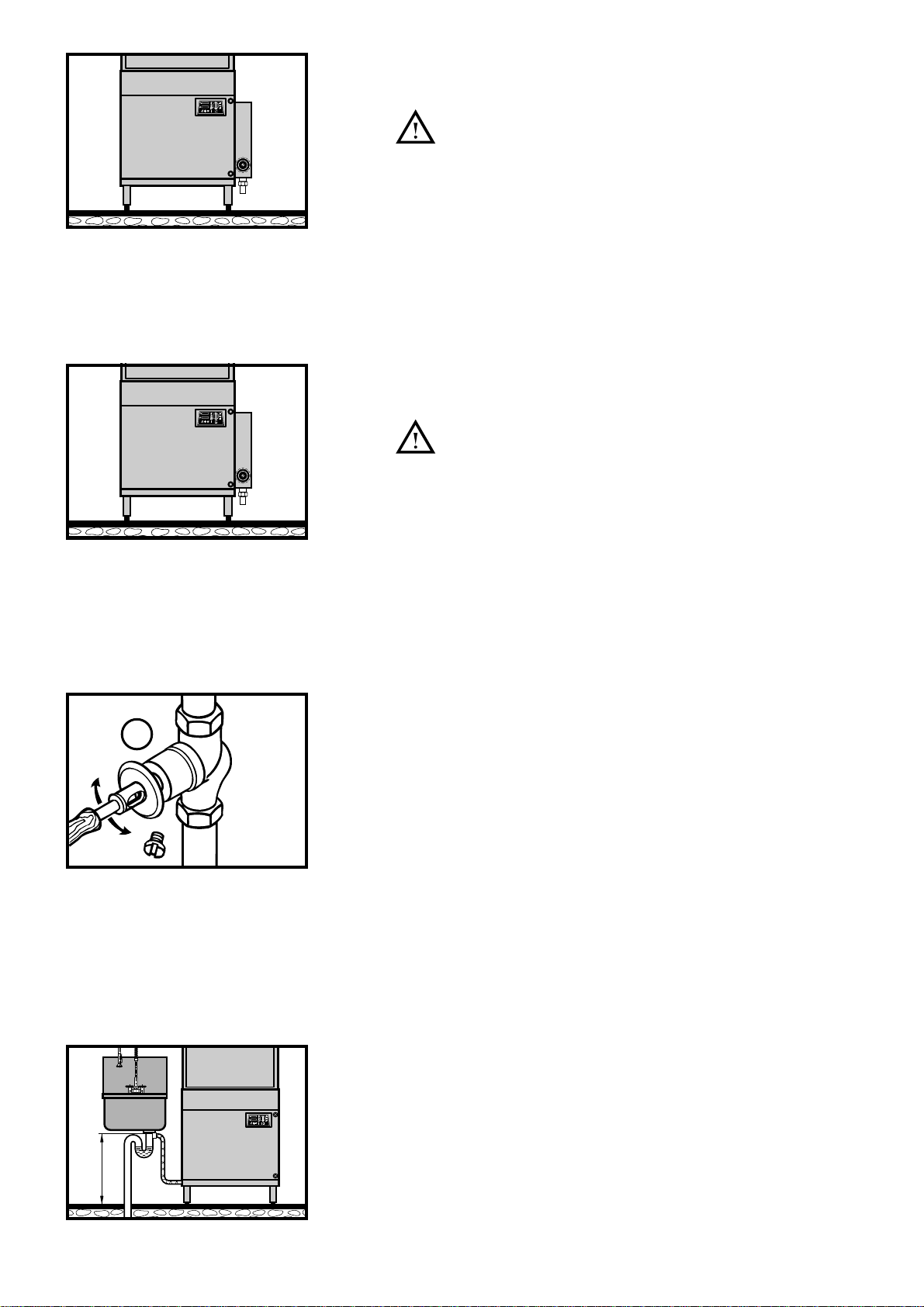
2.6 Drain connection
– Connection between machine and site drain must not exceed
max. height of drain pump lift of 0.8 m.
– Do not kink drain hose.
max. 0,8 m
5
Page 6

3 Controls
1 4 5 6
3 72
0
70
65
60
55
50
45
40
°C
90
85
80
75
70
65
60
891011
1. Detergent dispenser Pilot light illuminates: dispenser operates.
(built-in dosing pump Pilot light blinks continously through 2 - 3 cycles:
on option only) Container is empty or conductivity probe (located inside the wash tank)
must be cleaned.
For machines without dispenser: add detergent to tank.
2. Regeneration Pilot light blinks: indicating that regeneration is required.
(S-models only) Pilot light illuminates permanently: regeneration prog r amme is running
(duration approx. 45 minutes).
3. Filling Pilot light illuminates during fill cycle.
4. Drain Pilot light illuminates during drain cycle.
(At the end of drain cycle machine switches off automatically.)
5. Machine OFF
6. Thermometer At the end of a wash cycle the thermometer switches ov er.
Wash °C
°C
70
65
60
55
50
45
40
Now a light point moves up and down in short sequences
90
and indicates the end of the wash cycle.
85
80
After the doors are opened the display will s witch back into
75
70
the temperature mode.
65
60
7. Thermometer At the end of a wash cycle the thermometer switches ov er.
Rinse °C
°C
70
65
60
55
50
45
40
Now a light point showes the status of the softener.
90
The 1st light (top) illuminates: the softener has full capacity.
85
80
The 6th light (middle) illuminates: the softener has only
75
70
50 % capacity.
65
The 12th light (bottom) illuminates and the regeneration
60
pilot light blinks: the softener capacity is zero and needs
to be regenerated.
After the doors are opened the display will s witch back into
the temperature mode.
8. Programme button I 120 sec. Light duty programme
9. Programme button II 240 sec. Normal programme
10. Programme button III 360 sec. Heavy duty programme
11. Timer Pilot light illuminates during cycle.
6
Page 7

4 First run
4.1 Detergent
With built-in dispenser (option):
– Put suction hose (white) into detergent container.
If there is no dispenser in use:
– pre-dosage of detergent is necessary (approx. 150 gram).
4.2 Rinse agent
– Put suction hose (blue) into rinse agent container.
Be careful that you do not confuse the rinse agent
and detergent containers.
As high pressure and high circulation is needed for the
cleaning of utensils, use only commercial low foaming
detergent and rinse agent.
Do not use any acidic detergent products with the built-in
detergent pump.
Please pay attention to the manufacturers safety rules and
instructions.
0
0
0
4.3 Filling of rinse booster heater and predosing
°C
90
70
85
65
80
60
55
75
50
70
65
45
40
60
°C
90
70
85
65
80
60
55
75
50
70
65
45
40
60
°C
90
70
85
65
80
60
55
75
50
70
65
45
40
60
– Switch on the main switch.
– Open shut-off valve.
– Close the doors.
– Push fill button and wait until pilot light of programme II button
illuminates.
The filling time depends on the rinse booster heater and the
water feed temperature (approx. 30 min with 9 kW booster
and 10°C water feed temperature).
– Push programme III button, open and close machine doors.
– Push the timer button, timer pilot light illuminates.
Detergent pump operates, detergent dispenser light illuminates,
wash cycle starts.
– When wash and rinse cycle is over and detergent dispenser
light is still blinking (sign for a too low concentration), repeat the
wash cycle until the light goes off. Open and close machine doors.
4.4 Check
– Open doors and check if upper and lower wash arms rotate
smoothly.
– Check and eliminate any leakages of supply and drain pipew ork.
– Check direction of rotation of pump motor (see direction sign).
If motor runs against the indicated direction (pump is running
noisily and circulates only a little water) interchange 2 phases
(threephase current only).
This must be carried out by an authorized
technician.
7
Page 8

5 Adjustment of detergent concentration
The detergent concentration can be adjusted within 12 steps,
depending upon the water quality and wash result.
The concentration is set at step 4 at the factory.
If the concentration needs to be changed:
– Shut off machine (press machine OFF button).
– Open machine doors.
90
¡C
85
0
8
70
65
75
0
0
6
7
0
65
55
0
6
50
5
4
40
0
°C
90
70
85
65
80
60
55
75
50
70
65
45
40
60
– Press and hold programme button II, tap the timer button.
The wash thermometer column indicates the detergent
concentration (e.g. 50°C means step 4 of 12 steps).
– Each time the timer button is tapped, the dosage is increased
by one step. When level 12 is reached, the dosage will start
again at level 1 if procedure continues.
– After approx. 8 seconds the thermometer column switches off.
– After adjustment close doors and operate machine as usual.
6 Adjustment of rinse agent concentration
The rinse agent concentration can be adjusted within 8 steps,
depending upon the water quality and wash result.
The concentration is set at step 3 at the factory.
If the concentration needs to be changed:
– Shut off machine (press machine OFF button).
– Open machine doors.
0
9
¡C
5
8
0
0
8
7
5
5
6
7
0
0
6
7
0
5
5
6
5
0
6
50
5
4
40
0
°C
90
70
85
65
80
60
55
75
50
70
65
45
40
60
– Press and hold programme button III, tap the timer button,
the rinse thermometer column indicates the rinse agent
concentration between 60°C and 80°C (ignore 80°C to 90°C).
– Each time the timer button is tapped, the dosage is increased
by one step. When level 8 is reached, the dosage will start again
at level 1 if procedure continues.
– After approx. 8 seconds the thermometer column switches off.
– After adjustment close doors and operate machine as usual.
The dosage of rinse agent and detergent depends on the
quality of water.
For economical use of detergent and rinse agent at optimal
levels, adjustment should be in accordance with chemical
suppliers recommendations.
8
Page 9

7 Softener (S-models only)
0
0
°C
70
65
60
55
50
45
40
°C
70
65
60
55
50
45
40
7.1 Adjustment of water hardness
90
85
80
75
70
65
60
90
85
80
75
70
65
60
– Switch off machine (press OFF button).
– Open machine door.
– Press regeneration button and hold it. Tap timer button.
– The LED’s at the left side of the regeneration button illuminate
one after another. The lowest is position 1, the middle is position
2, the top is position 3.
Adjustment of softener according to schedule.
Pos. Water Water quantity until Rack quantity until
hardness next regeneration next regeneration
1 7-12° clark 1300 litres approx. 150 racks
2 13-24° clark 650 litres approx. 80 racks
3 25-36° clark 430 litres approx. 60 racks
– To ascertain water hardness level ask local water authority.
– The softener is factory adjusted to position 3.
0
0
7.2 Regeneration
When the machine is delivered, the softener is already
regenerated.
– When regeneration pilot light blinks (indicating that salt is
required), press drain button.
– When the drain pilot light switches off, open the doors.
– Unscrew the softener lid.
– Fill dispenser with 1 kg powdered salt (salt tablets are not
recommended). Clean seal and rim of softener lid and
border carefully befor closing the lid.
– Close lid and tighten.
IMPORTANT: only fill with salt just before starting the
regeneration programme.
The running regeneration cycle cannot be interrupted.
°C
90
70
85
65
80
60
55
75
50
70
65
45
40
60
°C
90
70
85
65
80
60
55
75
50
70
65
45
40
60
– Close the doors and press regeneration button.
The pilot lights regeneration and timer illuminate permanently,
cycle is running.
Attention:
Do not open the doors during regeneration.
– After approx. 45 minutes the pilot lights of regeneration and
timer button switch off, the regeneration is finished.
– Press the fill button.
– After filling, programme button II pilot light illuminates.
Machine is ready for operation. Select a washing programme.
Notice:
The regeneration can even be done, when regeneration pilot lamp
does not blink (for instance at the end of the day before leaving).
The regeneration button has to be pressed for at least 5 seconds.
9
Page 10

0
40
45
50
55
60
65
70
75
80
85
90
60
65
70
°C
8 Operation
8.1 Preparation
Do not confuse the
containers!
Detergent (only on option):
White hose!
Rinse agent:
Blue hose!
Check correct position of wash Check level of detergent and rinse Close the doors and push the fill
arms, rinse arms, foam sheet and agent containers. button. Tank will be filled.
strainers. Do not run the dosing pumps for
Open shut-off valve and switch long periods without a liquid in the
on the main switch. containers.
Remove coarse food soil. Insert sheets into the frame. Put pots and pans facing down-
wards into the racks.
8.2 Racking
Protect light washware
by putting on a rack.
10
Page 11

8.3 Washing
0
4
0
4
5
5
0
5
5
6
0
6
5
7
0
7
5
8
0
8
5
9
0
6
0
6
5
7
0
¡C
for lightly soiled
washware
for normally soiled
washware
when food soil
is dried on
90
¡C
85
80
70
65
75
60
70
0
65
55
60
50
45
40
Select programme. Put rack into the machine, close When wash cycle is finished (see
door and press timer button. chap. 3), open doors and take out
Wash cycle starts. rack.
Allow washware to dry for 1 min.
approx.
9 Cleaning the machine (daily)
NOTE:
During the drain cycle, the
interior of the machine is
cleaned automatically.
A final inspection is
90
¡C
85
80
70
65
75
60
70
0
65
55
0
60
5
45
0
4
recommended.
Close the doors and push the drain When drain pilot light switches off, Take out strainers and foam sheet.
button. open doors and switch off machine.
Pilot light drain illuminates, drain Set main switch to "0" and close
cycle is running. shut-off valve.
11
Page 12

Flush strainers and foam sheet. Put strainers and foam sheet back
into place.
Leave the doors open f or ventilation.
If required:
2
1
Take out wash and rinse arms. Open plugs of wash and rinse arms Clean the pins of the conductivity
Use the strainer as a spanner to and flush. probe (on tank bottom) with fine
loosen the hexagon screw (1) by sand paper (grain 180).
turning it counter-clockwise (2).
12
10 Frost prevention
In case of frost or longer operation pauses (e.g. during seasonal
operations) the machine must be completely drained.
This should be carried out by HOBART after sales service.
Please contact your local HOBART Office.
Reset for operation according to chapter 4.
11 Maintenance
For trouble free operation we recommend you enter into a
service contract with your local HOBART Service Office.
Page 13

12 Trouble shooting guide
TYPE OF FAILURE POSSIBLE CAUSE REMEDY
Poor wash result
Washware is not clean. Wash arms stiff (you should be able Take out wash arms and clean them thoroughly.
to turn them easily by hand). Check water outlet from machine to wash arms is
clear.
Wash arm nozzles are clogged Take out wash arm, remove cleaning cap and
(visual check). rinse wash arm thoroughly until soil is removed.
Replace correctly.
Rinse arm nozzles are clogged Remove rinse arms and decalcify them in
(generally through lime deposit). separate container.
Detergent concentration is too low or Check setting of detergent concentration
too high. (usually on 4).
See also operating instructions point 5.
Coarse strainer soiled. Take out strainer, empty and clean it.
Fine strainer soiled or obstructed Take out fine strainer. If heavily soiled soak in a
through lime. vinegar solution. Then clean it thoroughly until
the pores are free.
Cleaning is to be done daily (see operating
instructions).
Wrong programme selected for heavily Select programme with longer wash cycle.
soiled washware.
Washware does not dry Rinse aid concentration too low. Increase concentration (see operating
properly. instructions).
Washware still greasy. 1. Detergent concentration too low: increase
(see instructions).
2. Check if detergent is appropriate, if not choose
a stronger one.
3. Drain soiled water and refill machine. Check
pre-scrapping procedure.
Washware stays too long in the Take out washware as soon as cycle is completed
machine at the end of programme. to enable it to dry.
Stripes and staines on Rinse aid concentration too high. Reduce quantity (see instructions).
washware.
Hard water or high mineral content. Check water quality.
Obtain details from local water authority.
Recommended values:
Ideal degree of hardness is 4° Clark.
Ideal conductivity value for glasses is max.
200 µS/cm and for dishes max. 400 µS/cm.
Insufficient rinse aid concentration Increase quantity (see instructions).
causes staines.
Machine with softener:
use of wrong type of salt (too coarse). Use only fine salt.
Machine with softener:
salt container is full although softening Only fill with salt just before regeneration
does not take place. programme will be activated.
Trouble with foam
Machine gets much louder Foam production above average Use suitable detergent and rinse agent
during wash cycle. caused by unsuitable detergent and (see chapter 4).
rinse agent.
Foam production above average Pre-clean washware.
caused by contact of foam producing
substances (albumins etc.).
13
Page 14

TYPE OF FAILURE POSSIBLE CAUSE REMEDY
Electronic control panel
All LED lights are flashing. Water supply tap not open or only Open tap.
partly open.
Strainer or water supply line is dirty. Clean it. If necessary replace with heavy duty
filter (available as accessory).
Site line pressure too low. Improve pressure conditions on site
(seek professional advice).
Rinse arm pivot clogged. Clean thoroughly.
All LED’s are flashing plus Control system malfunction. Call HOBART service.
any on the temperature
gauge.
Softener malfunctions
(only applicable to machine
with softener)
Machine fills and Softener lid is not tight. Tighten lid as well as possible.
immediately drains again.
Regeneration pilot light Regeneration programme has been Let regeneration programme run until pilot light
blinks permanently. interrupted as door was opened switches off (duration approx. 45 minutes).
during cycle was running. Never open the door during cycle is running.
Lime deposit in the Regeneration call was "ignored" i.e. Run regeneration programme 2–3 times
machine. the machine went on washing when (refill salt container every time).
regeneration was needed. If required: decalcify the machine.
Strainer in water supply pipe clogged Clean it. If necessary replace it with heavy duty
(in site tape). filter (available as accessory).
Salt container not tight. During filling, salt was split onto Open softener lid, remove salt with a cloth and
the edge and not removed. close lid tightly.
Other malfunctions
Machine suddenly stops Machine is connected to a "maximum Connect machine separately (call electrician).
during wash programme. power supply unit", which cuts out the
energy consumer at a given point, or
machine is interlocked with another
energy consumer unit.
Blown site fuse. Check site fuses.
14
Page 15

15
Page 16

As continued product improvement is a policy of HOBART, specifications are subject to change without notice.
Printed in Germany AG-20937-A-11-99-PC
 Loading...