

Page 1
UCX
Container Washer
INSTALLATION OPERATION
Page 2

2
Page 3

Installation and Operation Instruction
for HOBART Container Washer
Model UCX
Content Page
1 Assembly .............................................................................................. 4
2 Electrical connection ............................................................................. 5
3 Water connection .................................................................................. 5
4 Steam or high pressure hot water connection ...................................... 6
5 Dosage of detergent and rinse agent ................................................... 7
6 First run................................................................................................. 7
7 Controls............................................................................................... 10
8 Preparation for use.............................................................................. 12
9 Operation ............................................................................................ 12
10 After washing ...................................................................................... 13
11 Position of curtains.............................................................................. 14
12 Frost preventation ............................................................................... 14
13 Trouble shooting guide........................................................................ 15
Machine noise level is 77 dB (A)
Important Notes
● Use in Accordance with Regulations
This machine is exclusively to be used to clean ware such as containers.
Do not use for electrically heated cooking and heat conservation
appliances.
● Safety
Never hose down the machine.
The "Attention" symbol is shown beside instructions that are essential
for the safe operation of the machine. Please read these passages very
thoroughly.
Safety during service:
No service to the machine or any of its components should be performed
without all electrical supply to the machine cut off.
● Liability
Installations and repairs which are not carried out by authorized technicians or the use of other than original spare parts, and any technical
alterations to the machine, may affect the warranty set out in the
standard conditions of sale.
● Important
This Instruction manual is written for machines with an operating direction
from left to right. For machines with an operating direction of right to left,
the same description is valid in opposite sence.
3
Page 4
1 Assembly
Should be carried out by a HOBART technician.
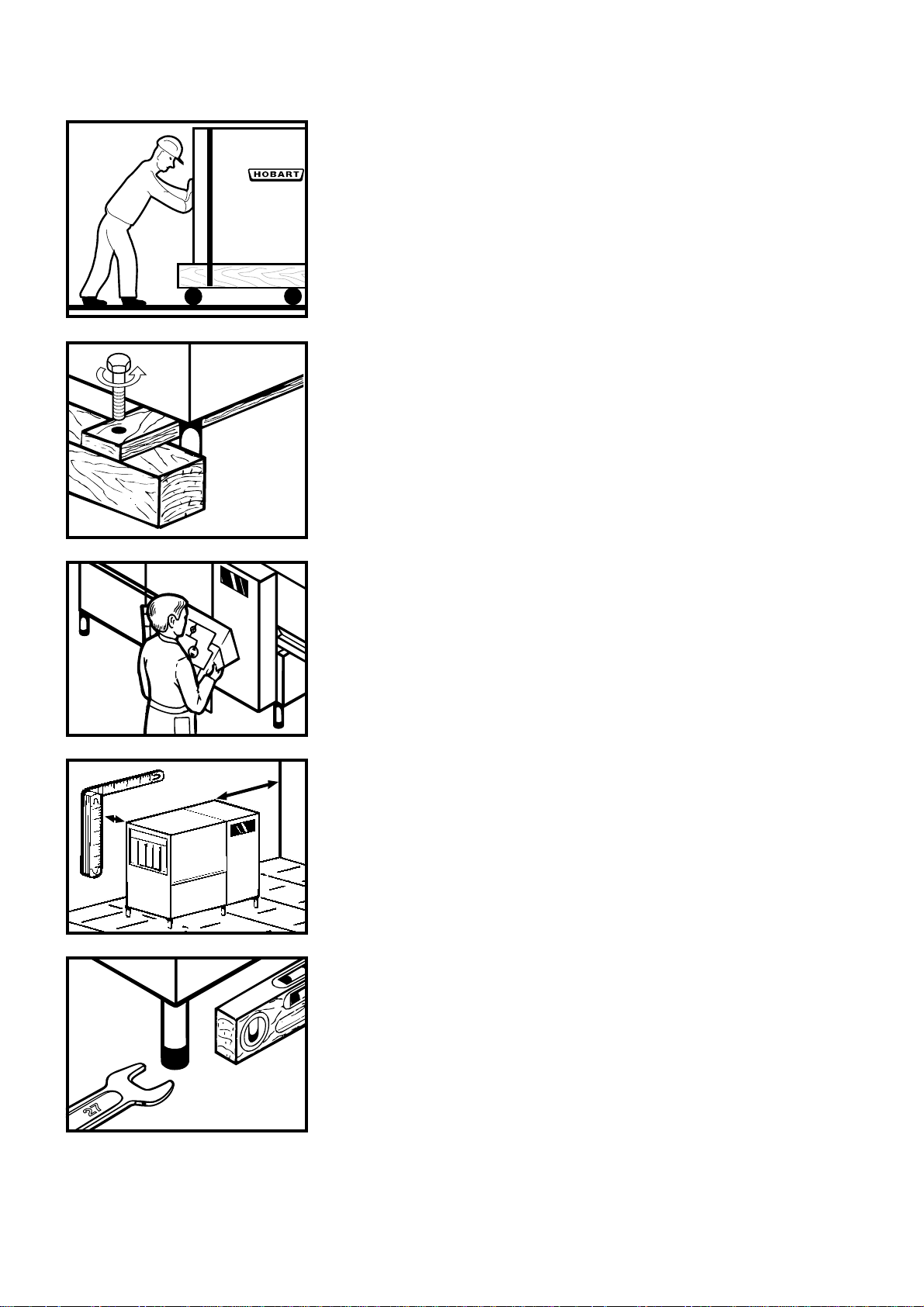
1.1 Transport to installation location
– If possible in its packing and on skid.
– Push on rollers.
– Avoid damage to floor and doors.
1.2 Remove packing
– Cut steel bands.
– Remove carton.
– Remove wooden skid.
– Remove inside packing material and accessories.
1.3 Locating
– According to installation plan.
– Consider wall clearance (normally 70 mm).
– Consider length of tabling etc.
1.4 Adjusting machine height
– Level machine to compensate floor unevenness.
– Distribute machine weight equally onto all feet.
4
Page 5
2 Electrical connection
Must be carried out by an qualified technician according
to the national and local codes.
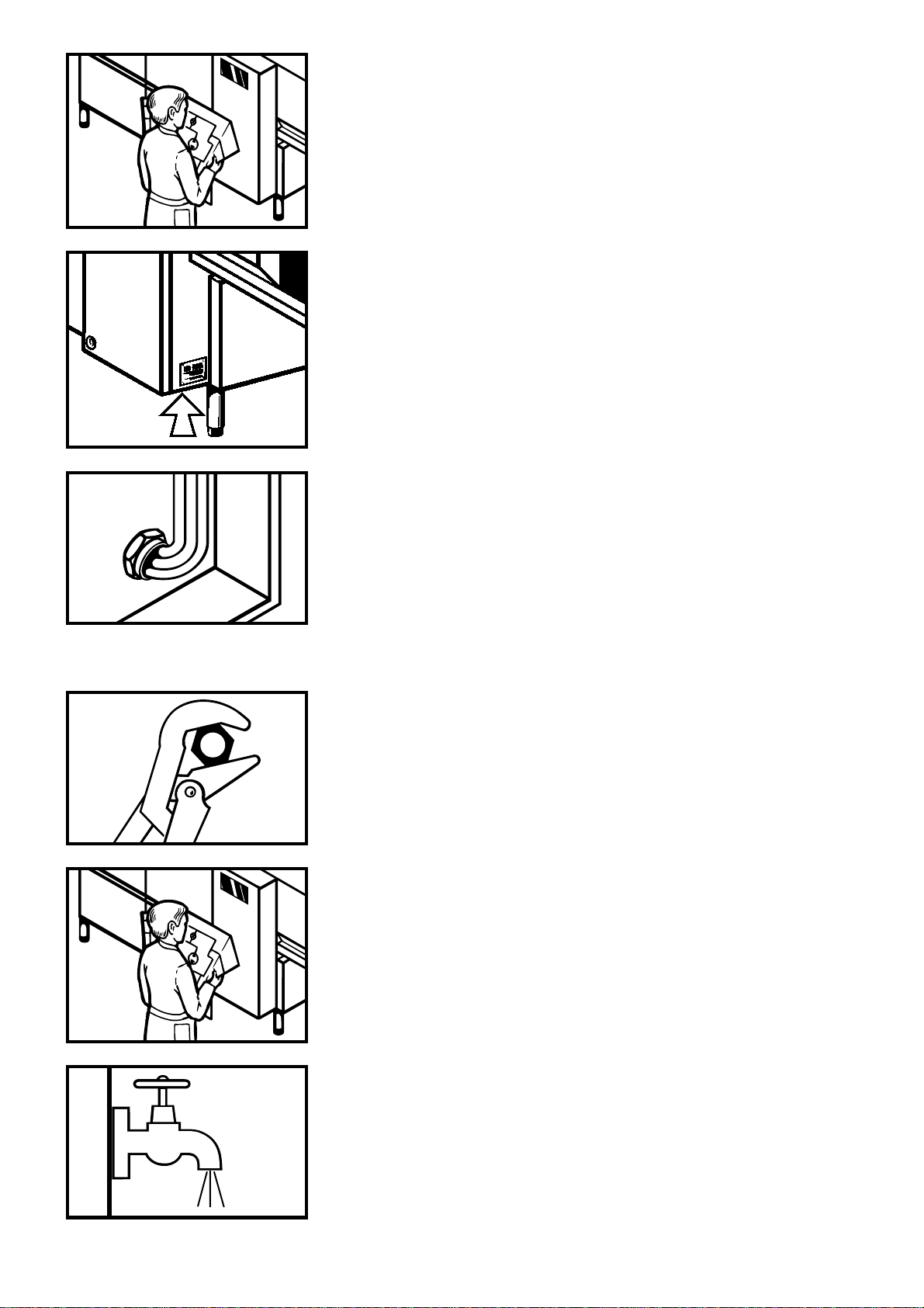
2.1 Check
– Open control box (with key) and take out wiring diagramme from
the inside of the door.
– Check machine specifications to make sure they correspond to
those of the site supply and the wiring diagramme.
– Check site fuse rating.
– Provide a main switch at site, close to the machine (if the
machine is not supplied with a built-in main switch).
2.2 Connection
– Draw cable through cable gland at the bottom of the rear panel
of control box.
– Connect wires to main terminals or to main switch (if installed).
– Tighten all terminal screws (may be loosened during transport).
– Tighten the cable glands.
3 Water connection
Must be carried out by an authorized technician according
to the local codes.
3.1 Check
– Make sure that site water supply and drain pipes correspond
to installation plan of machine.
– Identify which pipes are to be connected to corresponding
connections of machine.
– Check correct size of pipe inside diameters.
– Line strainer, pressure reducer, vacuum breaker and safety
valve are fitted to machine as standard.
3.2 Fresh water supply for rinse DN 15 (1/2")
– should be soft (2 to 5 °Clark, resp. 1,08 mval/l).
– Provide shut-off valve at site.
5
Page 6

3.4 Drain connection
to be connected to site drain:
– Tank drain (50 mm Ø).
– DUAL rinse drain (hose 3/4")
– Drip water drains of tabling, sink and other elements.
– All drains must be connected to goose neck (individually
or single point).
4 Steam or high pressure hot water
connection
Must be carried out by a qualified technician according
to the national and local codes.
NOTE FOR INSTALLATION
Make sure that pressure and temperature of the heating
medium do not exceed values indicated in the installation plan.
4.1 Check
– Make sure that site supply corresponds to installation plan
of machine concerning temperature, pressure and energy
consumption.
– Identify which conduits are to be connected to corresponding
connections of machine.
– All connections are equipped with necessary fittings and valves
as standard.
4.2 Connection
– When single point connection:
connect all supply and return pipes to central connections of the
machine.
– When individual connections:
following units must be connected to supply and return pipes:
- rinse booster heater (below of the rinse module).
- tank heating (in the wash module).
4.3 Insulation
– All pipes should be insulated.
– Insulating material should be water, heat and shock proofed.
6
Page 7

B
A
5 Dosage
of detergent and rinse agent
– Normally, dispensers and controls are delivered and installed by
the detergent and rinse agent suppliers.
– Install dispensers, controls and containers in such a way that
they are easy to handle and do not disturb machine operation.
– Rinse agent connections are provided for choice before (A) and
after rinse booster heater (B).
– T erminals are provided in the control box (see wiring diag ramme).
Use only commercial detergent and rinse agent (suitable
for professional and industrial operations).
Please pay attention to the manufacturers safety rules
and instructions.
6 First run
Must be carried out by an authorized HOBART technician to
adjust and check machine functions.
6.1 Preparation
– Check if detergent and rinse agent containers are filled.
– Open water supply.
– Switch on all relays at the control box.
If electrical heated rinse booster heater is installed:
make sure that its fused isolator is switched off (see wiring
diagramme).
– Switch on main switch.
– Switch on site exhaust extraction (if exists).
– Close inspection doors.
– Push green get-ready button.
Tank fill starts (fill symbol illuminates). When sufficient water
level is reached the heating switches on automatically.
Once tank is filled, fill symbol goes out.
– Switch on green operation button.
Conveyor, pumps, etc. start to operate.
7
Page 8

6.2 Fill rinse booster heater
l/h 100 200 300 400 500
bar
0,1
0,2
0,3
0,4
0,5
0,6
0,7
– Fill machine until water sprays out of rinse jets.
– Electrically heated machine:
Switch on fused isolator of rinse booster heater. Heating
switches on.
– Steam / high pressure hot water heated machine:
Open heating valves.
6.3 Check
– Direction of rotation of motors:
- pumps (see direction sign)
bar
– Check and eliminate possible leakages on:
- drain
- water supply pipework
- heating pipework
- machine housing, bottom of tanks.
6.4 Adjust flow pressure
at the pressure gauge of the rinse fill line.
8
Page 9

P1
6.5 Adjust temperatures
Must be carried out by an authorized HOBART technician.
RINSE BOOSTER HEATER
L1L2
S1
P2
Actual temperature
– Measure temperature at water outlet (contact thermometer).
– Set switch "S1" at the rinse booster circuit board to right
position.
– Adjust "P1" until digital display "L2/L1" and actual temperature
correspond.
Pre-set temperature
is adjusted at the factory and sealed.
– To check pre-set temperature on display "L2/L1" set switch "S1"
to left position.
TANK HEATING
Actual temperature
– Measure temperatures of tank water.
– Adjust "P1" until digital display "L2/L1" and actual temperature
correspond.
Pre-set temperature
UCX wash ≈ 55°C
A
D
6.6 Conveyor motor
If the racks do not arrive at end of the exit table at maximum
capacity: increase force of conveyor system (below rinse section).
– Loosen lock nut "K".
– Reduce distance "D" by turning the spring fitting "A".
– Retighten lock nut "K".
K
9
Page 10

7 Controls
7.1 Get-ready button (green) switches on:
– rinse booster heater
– fill
– tank heating
7.2 Shut-off button (red) switches off all above functions
Machine is off duty.
0
II
7.3 Operation button (green) switches on:
– conveyor
– wash systems
7.4 Off button (red) switches off all above functions
Machine stays ready for operation.
7.5 Optional:
I
Selector switch for 2 different conveyor speeds
I = slow
0 = off
II = fast
10
Page 11

7.6 Function display
1 2 3 4 5 6 7
Functions: Temperatures:
8 9
°C °C
1 not used 8 wash
2 rinse booster heater 9 rinse
3 fill
4 tank heater
5 wash pump
6 rinse
7 not used
Green lamp illuminated: temperatures correct.
°C °C
If green lamp goes out, temperature of the tank
dropped 15°C below pre-set value: check heaters.
°C °C
Yellow lamp illuminated: motor failure.
Illuminated symbol (*) of defective motor goes out.
Check motor circuit.
**
11
Page 12

8 Preparation
Put curtains in place. Check correct strainer position. Check wash arms.
I
0
Close inspection doors Switch ON main circuit breaker "I". When green lamp illuminated,
(drains close automatically). Push get-ready button. machine is ready for operation.
Push operation button.
9 Operation
°C
50
?
Slide washware into the machine. Check temperatures from time to Check fill level of detergent and
(Guide over slide optional.) time. rinse agent containers.
12
Page 13

10 After washing
Push shut-off button. Remove and clean strainer baskets Remove and clean wash arms.
Set main switch to "0" and open and flat strainers.
inspection doors.
Take out curtains. Drain tanks by lifting lever at left Hose down interior of machine.
tank wall. Leave doors open.
7
Put strainers in place. Put curtains in place. Check rinse arms once a week.
13
Page 14

11 Position of curtains
1
231 540-1
231 602-2
lg = 210 lg = 290 lg = 250 lg = 210 lg = 420
2
231 540-1
230 781
Mod.154120
Mod.154119
4
UCX
1
2
3
5
4
5
53
231 540-1231 540-3231 540-2
230 781231 602-2231 602-1
43
2
1
12 Frost prevention
Must be carried out by a qualified technician.
Set main switch to "0".
The magnetothermal elements on electrical boiler should be
disconnected.
All tanks, water pipework and armatures must be totally drained.
– Turn out plug at the bottom of the rinse booster heater.
– Loosen unions next to fill valve.
– Drain site water pipework.
– Drain traps of drain system.
– Steam / hot water heated machines:
drain all heating coils and pipes.
Reset for operation according to chapter 6.
14
Page 15

13 Trouble shooting guide
TYPE OF FAILURE POSSIBLE CAUSE REMEDY
tank fill too slow line strainer of fill clogged clean line strainer
solenoid valve defective call the HOBART after sales service
tank not filled to correct drain leaking check drain gasket
level
temperatures too low heaters defective check heaters, steam or high pres-
sure hot water supply systems and
thermostats – eventually call the
HOBART after sales service
washware is soiled after strainers wrongly positioned check strainers
cleaning
curtains are not fitted or wrongly placed check curtains
wash jets are clogged clean the wash arms
too low detergent concentration check detergent dispensing or let
adjust by supplier
temperatures too low check heating system
15
Page 16

As continued product improvement is a policy of HOBART, specifications are subject to change without notice.
Printed in Germany AG-20999-A-10-00-PC
 Loading...