

Page 1
•
MODEL PCN90 SERIES
ELECTRIC CONVECTION OVENS
CONVECTION
OVENS
peN90 ML-43719
\HOBART}
EXECUTIVE OFFiCES
TROY, OHIO 45374
FORM
16842
Rev.
A (4-90)
Page 2

- THIS PAGE INTENTIONALLY LEFT BLANK -
Page 3
Installation, Operation and Care of
PCN90 SERIES ELECTRIC CONVECTION OVENS
SAVE
THESE INSTRUCTIONS
GENERAL
The PCN90 Series electric convection ovens feature Perfect
equipped with a
The Model
The Model PCN902 consists
stack set for mounting one
The Model PCN902
Accessories available include additional racks and a removable stainless steel liner kit.
1/3
PCN901
h.p.
motor.
is a single
of
oven
is
a single PCN90
oven
which is furnished with a set of four
two single PCN90 ovens, a set of four
on
top of the other.
oven
furnished with a storage stand
Touch™
programmable controls. Each oven is
3
25
8"
on
adjustable stainless steel legs.
/4"
adjustable stainless steel legs, and a
four
6"
adjustable stainless steel legs.
INSTALLATION
UNPACKING
Immediately after unpacking, check the oven for possible shipping damage. If the oven is found to
save the packaging material and contact the carrier within
"
Prior to installation, test the electrical service to
be
sure that it agrees with the specifications
INSTALLING SINGLE OVENS
Installing Basic Oven (PCN90)
The basic oven must
other supports restricting air circulation
oven on the stand after uncrating.
Assembling the Legs
1.
Position the oven
2.
Attach the four leg assemblies to the bottom of the oven with the twenty-four bolts and lockwashers.
3.
Reposition the oven by setting it on its legs
be
installed
to
the Oven (PCN901)
on
its back, taking care not to scratch the sides.
on
legs or
be
mounted
on
the bottom will void the warranty. If using the modular stand, set the
in
the installed position.
15
days of delivery.
on
a modular stand. Installations
on
the
oven
on
concrete bases or
be
damaged,
data plate.
HOBART CORPORATION, 1989
©
-3-
Page 4
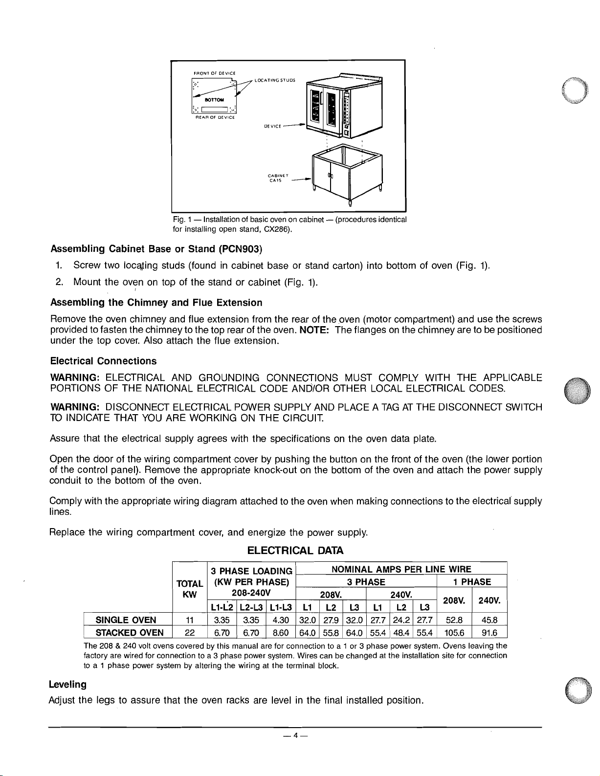
FRONT
OF
DEVICE
•
.0.
. .
:0:
~
REAR
Fig.
1 - Installation of basic
for installing open stand, CX286).
BOTTOM
c:::==::J
OF
DEVICE
••
'\
:0:
LOCAnNGSTUDS
oven
on
cabinet - (procedures identical
Assembling Cabinet Base
1.
Screw two
2.
Mount the oven
Assembling
loceuing
I
the
Chimney and Flue Extension
or
Stand (PCN903)
studs (found
on
top of the stand or cabinet (Fig.
in
cabinet base or stand carton) into bottom of oven (Fig.
1).
1).
Remove the oven chimney and flue extension from the rear of the oven (motor compartment) and use the screws
provided to fasten the chimney to the top rear of the oven. NOTE: The flanges
cover.
under the top
Electrical
Connections
Also attach the flue extension.
the chimney are to
be
positioned
on
WARNING: ELECTRICAL AND GROUNDING CONNECTIONS MUST COMPLY WITH THE APPLICABLE
PORTIONS OF THE NATIONAL ELECTRICAL CODE AND/OR OTHER LOCAL ELECTRICAL CODES.
WARNING: DISCONNECT ELECTRICAL POWER SUPPLY AND PLACE A
TO
INDICATE THAT
Assure that the electrical supply agrees with the specifications
Open the door of the wiring compartment cover by pushing the button
of the control panel). Remove the appropriate knock-out
YOU
ARE WORKING
ON
THE CIRCUIT.
on
the oven data plate.
on
on
the bottom of the oven and attach the power supply
THE DISCONNECT
the front of the oven (the lower portion
SWITCH
TAG
AT
conduit to the bottom of the oven.
Comply with the appropriate wiring diagram attached to the
oven
when making connections to the electrical supply
lines.
cover,
Replace the wiring compartment
and energize the power supply.
ELECTRICAL
3 PHASE LOADING
(KW
TOTAL
KW
SINGLE OVEN
I
I,
STACKED OVEN
The 208 & 240 volt ovens covered by this manual are for connection to a 1 or 3 phase power system. Ovens leaving the
factory are wired for connection to a 3 phase power system. Wires can be changed at the installation site for connection
to
a 1 phase power system by altering the wiring
11
22
PER PHASE) 3 PHASE 1 PHASE
208-240V
L1-L2 L2-L3 L1-L3
3.35
3.35
6.70
6.70 8.60 64.0 55.8 64.0 55.4
4.30
at
the terminal block.
DATA
NOMINAL AMPS PER LINE WIRE
208V. 240V.
L1
L2 L3
32.0
27.9
32.0
L2 L3
L1
24.2 27.7 52.8 45.8
27.7
48.4
55.4 105.6
Leveling
Adjust the legs to assure that the oven racks are level in the final installed position.
-4-
208V.
240V.
91.6
Page 5
INSTALLING DOUBLE OVENS
Assembling Stacked Ovens (PCN902)
1.
Position one oven
four leg assemblies with the twenty-four bolts and lockwashers provided.
2.
Place the lower oven (with legs)
the top cover plus the
3.
Install the two locating studs (included
upper oven.
4.
Remove oven chimneys stored at the rear of both ovens. Discard one chimney. Attach the remaining chimney
to
the top of the upper oven
under the top
5.
Move the oven with legs to the installed position and place the upper oven
the locating studs. Open the doors of the wiring compartment covers
both ovens. Also unfasten the control panel (of the lower
routing the power leads (furnished)
lock nut (also furnished).
6.
Attach the short flue extension over the exhaust vent
tube over the exhaust vent at the rear of the lower oven. These extensions should direct the exhaust fumes
upward through and above the top oven.
7.
Place the 1" conduit nipple through the 1%" hole
oven and clamp the two ovens together with the locknut from the underside.
(See
cover.
on
its back for access to the oven bottom, taking care not
on
Fig.
the floor and remove the two
Pia"
diameter knock-out
1).
(oven
without legs). NOTE: The flanges
at
the right front of the top cover.
in
the leg stack set) into the screw plates
t
oven
to
the top oven,
as
well
at
the rear of the upper oven. Slide the long flue extension
in
the bottom of the top oven and the top of the bottom
7/16"
only) and carefully pull forward. This will facilitate
as
attaching the one-inch conduit nipple and
to
scratch the sides. Attach the
diameter knock-outs
on
the under side of the
on
the chimney are
on
top of the lower oven using
by
pushing the button
on
each side of
to
be
on
positioned
the front of
Electrical
Connections
WARNING: ELECTRICAL AND GROUNDING CONNECTIONS MUST COMPLY WITH THE APPLICABLE
PORTIONS OF THE NATIONAL ELECTRICAL CODE AND/OR OTHER LOCAL ELECTRICAL CODES.
WARNING: DISCONNECT ELECTRICAL POWER SUPPLY AND PLACE A
TO
INDICATE THAT
YOU
ARE WORKING
ON
THE CIRCUIT.
Assure that the electrical power supply agrees with the specifications
on
the wiring diagram
1.
Attach the power leads to the line side of the terminal block of the upper oven. Then carefully route these
leads (furnished
the oven.
as
part of the stack set) down through the conduit nipple and behind the control panel of
TAG
AT
THE DISCONf\IECT
on
the oven data plate and complies with
SWITCH
the lower oven.
2.
Attach these leads to the lower oven terminal block per the wiring diagram.
At
the same time, attach the
power supply conduit to the bottom of the lower oven. Also attach the power supply leads to the line side
,of the terminal block.
3.
Finally, inspect and check all wiring and terminal connections for tightness and proper routing away from
on
any moving parts (relay solenoid core), or pinch points (cover
oven frame). Then carefully replace the
lower oven control panel and wiring compartment covers for both ovens.
ELECTRICAL
3 PHASE LOADING
(KW
PER
TOTAL
KW 208V.
L1·L2 L1-L3
SINGLE OVEN
I
STACKED OVEN
I
The 208 & 240 volt ovens covered by this manual are for connection to a 1 or 3 phase power system. Ovens leaving the
factory are wired for connection to a 3 phase power system. Wires can
to a 1 phase power system by altering the wiring
11
22
3.35 3.35 4.30 32.0 32.0 27.7
6.70 6.70 8.60 64.0 55.8 64.0 55.4 48.4
PHASE) 3 PHASE
208-240V
L2·L3
at
the terminal block.
DATA
NOMINAL AMPS
L1
L2
27.9
be
PER
LINE WIRE
1 PHASE
240V.
L2
L1
L3
24.2 27.7 52.8 45.8
changed at the installation site for connection
208V.
L3
55.4 105.6 91.6
240V.
Leveling
Adjust the legs to assure that the oven racks are level in the final installed position.
-5-
Page 6

INSTALLING OPTIONAL LINER KITS
~
Fig. 2 - Contents of
stainless steel liner kit for standard
36"
deep convection ovens.
CX581
l _
The
CX581
Steps to Adding Panels
WARNING:
INDICATE
IMPORTANT: Remove all protective lining material from stainless steel panels prior to installation.
Remove all racks
rack back is raised
liner kit components are identified above. Please follow the sequence shown below to install.
DISCONNECT ELECTRICAL
THAT
YOU
ARE WORKING
Fig. 3 Fig. 4 Fig. 5
by
pushing down slightly
to
clear, pull straight out
POWER
ON
THE CIRCUIT.
on
front of rack top to disengage the positive rack rear lock. When
as
shown in Fig.
AND PLACE A
3.
TAG
AT
THE DISCONNECT
SWITCH
TO
Remove both left and right rack guides
as
center, and pUlling out
shown
Remove aluminized steel back blower baffle
left to right to clear side brackets as shown in Fig.
Fig. 6
Install top panel by inserting screws
shown
Install new back blower baffle
as
baffle supports. No screws
Install bottom panel
in
Fig.
6.
shown in Fig.
7.
Then press panel
are
by
lifting over rack guide brackets and pushing straight
by
required.
by
in
lifting them straight
Fig.
4.
by
lifting straight
Fig. 7
(3
screws
in
5.
Discard this blower baffle.
front, 2
up,
tilting the bottom of the guides toward the oven
up,
then pulling forward and out. Tilt slightly from
Fig. 8 Fig. 9
in
back) and screwing tightly to top of oven interior
as
tilting the panel slightly from left to right to clear the side rack guide brackets
up
against the oven's back interior. Lift and lower panel until it rests
in
as
shown in Fig.
8.
on
blower
Install left and right side panels placing the cut-out notches over light bank (right panel), thermostat guard (right
,and
panel)
Reassembling Rack Guides and Racks
rack guide support brackets (right
Reassemble the left and right rack guides
Insert racks
in
rack guides (reverse procedure
and
left panels), Fig.
by
inserting them in support brackets (reverse procedure
in
Fig. 3).
9.
in
Fig.
4).
-6-
Page 7

OPERATION
BEFORE FIRST USE
Before the oven
the new surfaces
Using a clean damp cloth, wipe the inside
Wipe the outer surfaces
Close the oven
300°F;
is
used for the first time, it must
in
the chamber.
to
remove any dirt of film that may have accumulated during shipment.
door,
turn the oven ON, and program one of the products for [TIME = 6:00:00; TEMP =
FAN = 2;
CC
= 0]. Start a cycle for this product button. Smoke with
be
"burned in" to release any odors that might result from heating
of
I
the oven, including the racks.
an
unpleasant odor will normally
be given off. When the display shows DONE, press the product button to cancel.
If your oven has the painted finish, apply a generous coat of wax or another hard glossy finish that will protect
the painted surfaces.
CONTROLS
Become familiar with the location and function
of
the controls illustrated in Fig.
ON - OFF Switch
LIGHT Switch
10
before programming the oven.
DISPLAY
HEAT (LED)
START
PRODUCT
Fig.
PROGRAMMABLE CONTROLS
The maximum programmable temperature is
will flash HIGH TEMP and a warning beeper will sound.
475
0
F.
If the temperature in the
10
CLEAR/ENTER
COOL/TEMP
PRODUCT (LED)
Product Strip
oven
should reach 5000 F.
the display
The maximum time that can
be
programmed is
19
hours, 59 minutes and 59 seconds.
-7-
Page 8

There are
four stages of cooking with TEMPerature,
on the first stage only but is
10
PRODUCT buttons (0-9) which may be programmed to automatically schedule one, two, three and/or
TIME,
FAN
in
effect for all stages.)
TEMP - Degrees Fahrenheit or Centigrade
TIME - HHMMSS
FAN
- 0 = Low Speed (during heat cycle), Otherwise
1 = Low Speed Continuous
HH
= Hours MM = Minutes SS = Seconds
and Cooking Curve setting for each stage. (CC is programmed
Off
2 = High Speed Continuous
CC
- 0 - 15 = See Cooking Curve
COOKING CURVE (CC): A relationship between temperature and time. If the oven temperature drops below the
set temperature for any reason, the control will compensate for that loss. The length of time between counts of
the timed countdown will increase to compensate for the temperature loss. The higher the CC number selected
"0"
the greater the increase. A cooking curve of
will not compensate for any change
in
temperature.
1 to 3
3 to 5
5
to 8
6 to 9
7 to 9
8
to
10
9 to
11
to
13
SETIINGS
SUGGESTED CC
Baked potatoes
Beef roast
Pies
Bread, cake
Buttermilk biscuits
Muffins
Cookies
Bacon
Generally the more delicate items will require the higher CC settings.
12
MANAGER SECURITY
The program for each PRODUCT may be operator or manager programmed. A manager programmed product
requires the
may not be changed or removed without first entering the
4 digit manager code
[0123J
to be entered before entering the program. Manager programmed products
4 digit manager code.
SERVICE
If a condition exists which requires a service call, the display will flash SRVICE each time the oven is turned
or just before
as long
servicer should be called.
'-
01\1
is displayed. Diagnosis and display of a problem will not interfere with the operation of the oven
as
the oven is operable. If the display reads OPEN or SHORT, the unit will not operate and an authorized
on
PROGRAMMING MODE
Please read entire instruction before beginning programming mode.
With ON/OFF switch ON
DISPLAY DO
1.
2.
ON Press CLEAR ENTER.
ENTER
...
Within 4 seconds you must press a PRODUCT (0-9). If you
wish to program a manager's PRODUCT, enter the Code
[0123J
Wait 5 seconds.
prior to a PRODUCT (0-9).
-8-
Page 9

Programming Mode (Cant.)
Ii
tl
,~
3.
4.
5.
6.
7.
DISPLAY
TIME-1
HHMMSS
TEMP-1
XXXF
FAN-?
FAN-X
CCO-15
CC-XX Press
TIME-2 If
DO
Enter the time for the
on
display.
2 and 4 zeros.
Press
Enter temperature for first stage.
Press
Enter fan setting for first stage.
o =
=
1
2
= High Speed.
Press
Enter the Cooking Curve
you
Repeat TIME, TEMP and
and/or 4
only at a
For
example:
START
START
Low
Low
START
START
wish to stop after this stage, press 0 and go
or wait 5 seconds.
or wait 5 seconds.
Speed (during heating cycle), Otherwise Off
Speed
or
or wait 5 seconds.
by
repeating steps
TI
ME prompt.
w~t
1st
stage. Time is entered right to left
To
enter 2 hours you must enter a
5 seconds.
(0-15).
FAN
settings for stages
3-5
as
required.
You
to
step
2,
3
may exit
8.
U
~
CC
The
8.
If
you
make a mistake and wish to step backward through a program you may do
you
When
program.
If you wish
9.
10.
If you wish to clear a PRODUCT program, simply press
To
clear a PRODUCT program that was entered with the manager code [0123],
[0123].
PRODUCT STRIP: After you program a
write directly
if products change.
000000
STORED
PROD-?
have corrected your error
If
you exit
to
I
on
by
review a program that has already been entered.
ON
TIIVIE-1
the strip with a permanent type felt tip marker or use labels which may
flashes
(Program was saved.)
you
pressing
"0"
you
PRODUCT,
To
step
must step forward by pressing
will delete the remainder of the program.
Press CLEAR/ENTER and PRODUCT
Wait 5 seconds.
Press
through the entire program. If
you
you
setting is entered
enter another program press a PRODUCT (0-9). Go to
3.
To
exit program mode press CLEAR.
START
will delete the remainder of the program.
"0"
may identify the PRODUCT
to step through the program.
at the
TIME-1
on
START.
prompt.
stage 1
so
You
you
you
must enter the manager code
on
only.
by
pressing CLEAR/ENTER.
must step through the entire
to
be
reviewed.
You
must step
press
"0"
to
exit
the PRODUCT
be
removed and replaced
STRIP.
review,
Simply
-9-
Page 10

NORMAL COOKING
With ON/OFF switch
DISPLAY
101.
102.
ON
PRE-HT
or
COO
Optional
Press COOL/TEMP (once)
Press COOLITEMP (twice) S YYYF
Press COOLITEMP
103.
READY
"Beeper Sounds"
ON
...
DO
Press the number of the pre-programmed PRODUCT
instruction
(0-9).
LNG Wait for temperature
to
103.
The LED of the PRODUCT selected will flash and
other products with a
= Actual temperature.
= Set temperature.
to
PRE·HT or COOLNG.
(3
times)
A XXXF
Returns
Load Product.
Other lighted PRODUCT(s) may
is
preheat
satisfied. If you wish to cook one of these
products, load and press that
to
stabilize at the TEMP 1 setting.
TEMP-1
within
10
degrees will be lit.
be
selected since the
PRODUCT.
Go
104.
105.
106.
DOOR
READY
Countdown begins.
I HHMMSS I
Close
Press
door.
START.
The total time for all stages programmed will be displayed and countdown begins. The normal interval between
is
counts
Compatible Products
Products are compatible if they have only one cooking stage which has the same temperature and same
as the one-stage product being cooked. During the cooking cycle, compatible product LED'S will
the cooking cycle the door may
that PRODUCT number pressed. The display will flash
flash
cooking time
one second, but the interval may change due to temperature variation and the selected cooking curve.
fan
be
lit. During
be
NOT
opened and one of these compatible products may be put
"OK"
if the product is compatible. If not, the display will
COM
PAT.
If the product is accepted, the shortest cooking time will be displayed. If the new product
is
less than the remaining time for the original product, the new time will
be
in
the oven and
displayed and counted
speed
down. When the time expires and the beeper sounds, open the door and remove the new product, close the door
and
press CLEAR. The remaining time for the original product will
be
displayed and counted down.
-10-
Page 11

Normal Cooking (Cant.)
Batch Processing
,
•
This feature allows
example: PRODUCT 1
1.
When preheat
you
to bake several batches of the same product and stagger the loading and unloading. For
is
programmed
is
satisfied and oven
10
minutes
is
ready,~d
at
375°F with a fan speed of 2
product
and
press
START.
and a CC
of
9.
Press PRODUCT
Prepare second batch, load second
batch and press PRODUCT 1 again. The display will continue to countdown the original time until expired. When
the original batch is removed, press CLEAR and the remaining time for batch 2 will countdown. The
will compensate for temperature loss during loading and unloading. The number of
by
the oven capacity.
or
If
you open the door, the timer freezes.
If
you wish to cancel a program
Optional
...
Timer continues
Press COOLITEMP (once)
Press COOLITEMP
Press COOLITEMP
107.
Countdown ends.
(twiCe)
(3
in
process, press CLEAR/ENTER two times.
to
countdown.
A XXXF
S YYYF
times) Returns
= Actual temperature.
= Set temperature.
to
countdown HHMMSS.
batch~s
s.
is
limited
CC
to
selection
twenty
DONE
"Beeper Sounds" Unload product.
108.
DOOR
Close
door.
';r
To
continue cooking mode, press CLEAR/ENTER, go to
102.
step
To
exit cooking mode, press CLEAR/ENTER two times.
LOADING
Press the PRODUCT for the program you want
as
load the oven
~
open, temperature drops will occur. The control uses cooking curves to adjust the cooking time, allowing for these
To
drops.
minimize heat loss during loading, the doors should be open for the least amount of time.
quickly
Close the door and press
MODEL
PCN901
PCN903
PCN902
NO.
STD.
RACKS
5
10
as
possible. Since the oven chamber
START.
RACK
STD. RACK
SPACING
IN.
2.87
2.87
DATA
(Pan
OPTIONAL
RACKS
to
select. When the display shows
Capacities Shown For
11
NO.
6 1.25
12
RACK
SPACING
IN. IN.
1.25
READY,
is
large and loading requires keeping the doors
Single
RACK
SIZE
27.5
x 20
27.5
x 20 6 2 1
Rack)
9"
00
PIE TINS
6 2
open the door and
#200
PANS
18"
x
PANS
1
26"
CONSERVING ENERGY
Turn
•
off unused equipment.
•
Do
not open door unnecessarily; use window for observation of food
-11-
in
oven.
Page 12

COOKING TEMPERATURES AND TIMES
Because of the moving air
in
the convection oven, the temperatures required
to
bake various products are lower
and the cooking times are shorter than in a conventional deck-type oven with still
are
subject
in
this manual are
to
many variations and tastes, the guidelines regarding temperature settings
SUGGESTED
ONLY.
You
should experiment with your food products
temperatures and times that give you the best results.
GUIDELINES FOR BAKING AND ROASTING
PRODUCT TEMPERATURE TIME
BREAD PRODUCTS
Bread
(24,
1-lb.
loaves)
Hamburger Rolls
Corn Bread
Yeast
Rolls 325F 25 min.
Baking Soda Biscuits
PASTRIES
Frozen Berry Pies (22
oz.)
340F
300F
335F
400F
350F
Frozen Fruit Pies (46 oz.) 350F 45-50 min.
Fresh Apple Pie (20 oz.)
(5
Sheet Cake
Ibs. per pan)
350-375F
315F
Sugar Cookies 300F
Cherry Crisp
300F
Chocolate Cake 335F 20 min. 5
Cinnamon Buns
Brownies
Danish
Angle Cakes
Cream Puffs
335F
350F
335F
250F
350F
Pumpkin Pie 300F
Fruit Cakes
275F
Apple Turnovers 350F
MEAT
Hamburger Patties
Steamship Round (80
(5
per lb.) (well done)
lb.
quartered)
400F
275F
Steamship Round (whole 60-80 Ibs.) 275F 8 hrs. (med.)
lb.
Ibs.)
avge.)
300F
275F
375F
300F
Rolled Beef Roast (20
Prime Ribs
Baked Stuffed Pork Chops
Veal
Roast
Boned
(15
Lamb Chops (small lean) 400F 6 min.
(10
Shell Steaks
Meat Loaf
FISH
Fish Stix
oz.) 450F
325F 40-45 min.
335F
Baked Stuffed Shrimp 400F
(1112
Baked Stuffed Lobster
Halibut Steaks (Frozen 5 oz.)
FOWL
Ibs.)
400F
350F
Chicken Breast - Thigh 350F
Chicken Back - Wing
(21/2
lb.
Chicken
Turkey Rolled
OTHER
quartered)
(18
lb. Rolls)
Macaroni and Cheese
350F
350F
310F
350F
Beef Pot Pies 400F 30-35 min. 5
Turkey
Pot
Stuffed Peppers
Pies 400F 30-35 min. 5
350F
Melted Cheese Sandwiches 400F
Pizza (7" Frozen)
Idaho Potatoes
'Where the number racks is
(120
count)
5,
insert the first rack
on
the bottom position and place the others
435F
440F 50 min. 5
30
min.
15
min. 5
25 min.
6 min.
34 min. 5 (30 pies)
25-30 min.
20-22 min. 5
15
min. 5
25 min. 5
20 min. 5
15
min. 5
12
min. 5
25-30 min. 3
20-25 min. 5
30-35 min.
70
min. 3
15
min.
10-12
min.
3
2
/4
hrs. (well done)
4 hrs. (med.)
3 hrs. (med.)
25-30 min.
3 hrs.
10
min.
7-8
min.
16-18
min.
6-7
min. 5
10
min. 3
30 min. 5
33-35 min.
30-33 min. 5
30 min.
3
3
/4
hrs.
30 min.
15-20
min. 3
10
min.
11
min. 6
on
every other rung.
air.
Since recipes and foods
and
cooking times contained
to
determine the cooking
NO.
RACKS
3 (every other rack starting
with bottom rack)
5
5
5
5 (20 pies)
5 (30 pies)
5
5
11
(264)
(2
pans ea. rack)
2
1
(2
roasts per pan)
3
(2
roasts per pan)
2
5
2
5 (24 per pan)
(16-18
5
5
per pan)
(2
pans per rack)
11
5
5 (26 per pan)
(6
pan - 2 rolls ea. rack)
3
5
(120)
5
-12-
Page 13

CLEANING YOUR CONVECTION OVEN
Always allow the
minimize the exposure of the operator to the hot
Leave the door
Press the COOUTEMP button. The
oven
to
cool prior to cleaning. If the oven is hot, make sure the doors are only slightly ajar
air.
To
speed up the cooling process:
ajar.
fan
will come
on
at high speed and will turn alternately
on
to
and off each
time the COOUTEMP button is pressed.
When the oven has cooled sufficiently, set the
CLEANING THE INTERIOR OF YOUR
Ovens With Standard Aluminized Steel Liners
Keep
the inside of the oven and racks wiped clean. If food particles or carbon accumulate
ON/OFF switch to OFF and clean the oven.
OVEN
so
doors cannot be
tightly closed, heat is wasted and the oven will not operate properly. Poorly closed doors permit a constant escape
of steam and vapor around the door. This causes condensation which deteriorates the finish around the oven front
and door lining.
When cleaning the interior of your oven, it is important to bear in mind that the aluminum coating, though tightly
is
adherent,
still a coating.
cold with mild detergent
be
all the cleaning that
To
preserve the coating and for ease of maintenance, clean often when the
(or
soap) and
is
necessary.
water.
This will prevent food and dirt from "baking on" and will frequently
oven
is
Where soil resists soap and water cleaning, use a wooden tool to loosen spillage from the cold oven. Follow with
a non-etching cleaner which is specifically recommended for aluminized steel. Use clear water to rinse; dry with
a soft clean cloth.
DO
NOT
USE STEEL WOOL, WIRE BRUSHES
OR
CAUSTIC SOLUTIONS SUCH
AS
LYE,
SODA ASH,
AMMONIA.
Ovens With Stainless Steel Liners
In
general, the principles detailed above for aluminized steel apply. Soap or detergent and water will usually handle
routine cleaning; dry with a soft clean cloth.
For
burned-on foods and grease which resist simple soap and water cleaning,
mixed into a paste may
used. Apply with stainless steel wool
or
be
This treatment is equally effective for "heat tint" (slightly darkened areas caused
in
to rub
the direction of the polish lines. Rinse with clear water and dry with a soft cloth.
an
abrasive cleanser (scouring powder)
sponge, always rubbing with the "grain".
by
oxidation). Again, remember
REMOVING PANELS
WARNING: DISCONNECT ELECTRICAL POWER SUPPLY AND PLACE A
TO
INDICATE
Remove tray racks
Remove right and left rack guides by lifting straight
Right and left panels may now be removed
not rest panels
Remove bottom panel
Remove blower baffle
on
the side. Blower wheel can now
THAT
YOU
by
on
bottom panel.
by
ARE
WORKING
ON
THE CIRCUIT.
pulling straight out.
up.
by
moving toward the center and pulling out.
by
pulling straight out.
lifting straight up and pulling out toward the front. Care should
be
cleaned
as
described in Cleaning
TAG
AT
THE DISCONNECT SWITCH
To
avoid scratching, do
be
exercised
The
Blower Wheel, immediately following.
to
clear brackets
OR
Top
panel and stainless steel interior panels
can
be
cleaned while
in
place.
If
removal of top panel is desired, unscrew
three screws from front top edge of top and two screws from rear flange of top. Slide out toward front.
by
Reassemble
reversing the above procedure.
-13-
Page 14

CLEANING THE BLOWER WHEEL
WARNING: DISCONNECT ELECTRICAL POWER SUPPLY AND PLACE A
TO
INDICATE
Remove all racks
Remove both right and left rack supports
Remove the blower baffle
THAT
by
YOU
ARE WORKING
pulling forward, lifting
by
lifting
up
and pulling out. Wash blower thoroughly with hot sudsy water using a sponge
ON
THE CIRCUIT.
up
and out.
by
lifting
up.
TAG
AT
THE DISCONNECT
SWITCH
or plastic web pad. Rinse with clean water and dry.
Replace the hardware
by
reversing the disassembly procedure.
CLEANING THE EXTERIOR OF YOUR OVEN
Wash
all exterior surfaces at least once daily using a cloth with warm water and a mild soap or detergent. Wjlere
surfaces have been waxed, use the cloth lightly - hard rubbing will remove polish. Follow with a clear rinse, then
dry.
This simple treatment will keep your equipment clean and sparkling, and eliminates the danger of grease
accumulation.
Permalucent Finish
If
grease has accumulated and attacked the PERMALUCENT finish, use
on
the container. NEVER use a scouring pad
on
the PERMALUCENT finish.
any
silicon-based polish following directions
If the surface is accidentally marred, it can
be
quickly and easily restored with a "PERMALUCENT Touch-Up Kit",
available through your Dealer. Full instructions are in each kit.
Cleaning Stainless Steel Surface
To
keep the stainless steel front spotless, clean regularly with a damp cloth and polish with a soft, dry cloth.
remove discolorations which may have formed when regular cleaning
soap and water.
CAUTION: Always
For
particularly stubborn discolorations, a self-soaping scouring pad may
rub
with the
"Grain"
in a horizontal direction.
was
neglected, use any detergent or plain
be
used.
Rinse, dry and polish with a soft cloth. Avoid using gritty soaps or harsh cleaners.
REPLACING LAMPS
WARNING: DISCONNECT ELECTRICAL POWER SUPPLY AND PLACE A
TO
INDICATE
Remove all racks
Remove both the right and left rack supports
THAT
by
YOU
ARE WORKING
pulling forward, lifting
ON
THE CIRCUIT.
up
and out.
by
lifting
up.
Remove ten screws from the light window bezel.
Pull out the bezel and window.
TAG
AT
THE DISCONNECT
To
SWITCH
Replace the bulb(s).
Replace the hardware
by
reversing the disassembly procedure.
-14-
Page 15

CABINET BASE
(TYP.
*"
~~iH
:SCT":'r'M
FOR
CN901,(N911,CN~21,CN93IlIJN971,
FOOT) 8
WA.CK.
TO
FLOtR:)
ON981&-PCNC)OI
-2-g
711'U
t'
16
1.----.
CAI5
CAI6
(CN90,CN92,DN97&PCN90)
(CN91
FRONT
37
CN93
~
- ,
&-
DN98)
r
4C'2
16
[,£;.!Q
&ON>O
CN"'~
1
2'OOT
1
~':
.J'--2~
, CN931,
,'PCN901
DN971,DN98\;
j! 3
- -
I
-Jr' .
J
, t
i'TVPrcAL
L
'16-
8"'AX
,11)1-1.
_,
I)PEN
32~
16
,~
ON."
CN'O.
("'~,
PCH,t'1
" 3
jL
I
4 ADJUETMENT
~
(HP'
FO,:T
'DOT)
EACH
ll,'
I'
32'B"
I
-t1
'
~
CN9ul,
-.!fl
FRO
C
N911,
Y.Jf.IJ:1.
CN921
'D'
t I
,254"
3
'~
\--
}~!I_n
-,~;
[,J
!
.r__
=
======u_2j8~
j
J
______
[]J
- - -
---
[]J
I'
I' . .U
54~
0n
l
0l l
'.
CONOUIT
CONN£C"OH
In
1I
OVEN - I \ OIA. HOLE
LO(ATJON
wrTH
(.''NCENIHI(
I~OIA,
Itl
i'NC<K(Jul
&.
BA~[
[01
....
OF
, ,
,
,
,
L
II
lLCCATtCl1 Itl
a
((JNDUIT CrrlllEc.rlON
OVEN
BASr
54-t
I
r- ' 38'
130~-~
CotlOulr
CONNECTiON
r,--<---g=
1----'
,
PCN90,
PCN901,
PCN902,
PCN9C3
• PCN904
r----··,
38
l
MAX,OOC'K
r-15~~
aPfN"
,
...
3'
44~.ft1,C.~9.s
" 'j)'N97
CN9C),CN92
& peN90 I
'"
-;;1
& ON98
Clj90,
CN9'?
CN92,
DN97, DNSI?\,
CN93,
CN921.
CN931,
CN922, CN923, CN924
DN9;",
CN932, CN933,
DNS73,
CN934
DN974
"
,.'
CN903,
CN913,
CNS04,
CN914,
CN911
r'(
./...-TEFlMINAL
BLOCK
CN91,
CN90l,
CN902,
DN98,
DN9~
I,DN9S"
,DN983,
DN984
<.;,,"
1
I
5
'2
-""'."..
TOP
/~A)(.
/
SWINe
"
DOOR
VIEW
'.
,
-..
"-
Q
i
111
Oll
CX286
CX337~~
OPEN STAND
CN'lQ
CN9?,DN~7tPCN9Q
NOMINAL DIMENSIONS IDENTICAL
BASE
SIDE
S,
AS
&-
BACK,
SHOWN
BELOW,
EXCEPT
TO
LESS
CABINET
DOORS,
I
I
.
j
/'/'
,,~....
/,l
l,~
I I
"'I',
I
n
-I.::r
2
2~
C"'"HEYAI-l
<8
-
II'~
•
F44"~CN93
5
U(
....
,"IG
4
I"
@
NOTE:
I
TOP
~,OIA
CO\l[~
)(NO(l<DUT
fOR
ill
/
36'
CN90,CN92
BmL<
nOlO'"
l.40TaR
~,4.'K)
(NOT
FDA
2-5PEEO
SE,PMl
.•
TE
2 ib
-...c=-rC'"
I
L_~'4'fTI4
i61
I
uJ
I'
I'
'.
• .
.
/'N
I \
alA
BASE
HOLE
FOR
WITH
CONOUIT
I~
(1IJ'.
CONN"tlON,
&.
2~(
11'1
(ON~~N1RIC
f2
a:
:::E
····
,
1
J
m,['
I-LI1
,
2
2"
8
I
ADJ.
(TYP~E"'CH
FOOT
FOOT)
a:
~
I
ce
~
I
"BLO'Wffi
2
SPEED
MOTOA.
J
1
1
20"
LO
...
~._-:
;J
"
r~FOR
SPEED
MOTOR.
l~
I
i
I
I FLUE
:
rr
EXTENSIONS
;-'\;:
..
'I-L
I 8
7
I
DN97
&,IDN98
& PCN90
KNGCI<QUT
it
D.
!Z
w
c
2':
::i
en
~
 Loading...