

Page 1
P660 MIXERS
P660CE MIXER
single speed
ML-134201
ML-134202
(single speed)
(two speed)
F-23196 Rev. A (Apr. 2003)
Page 2
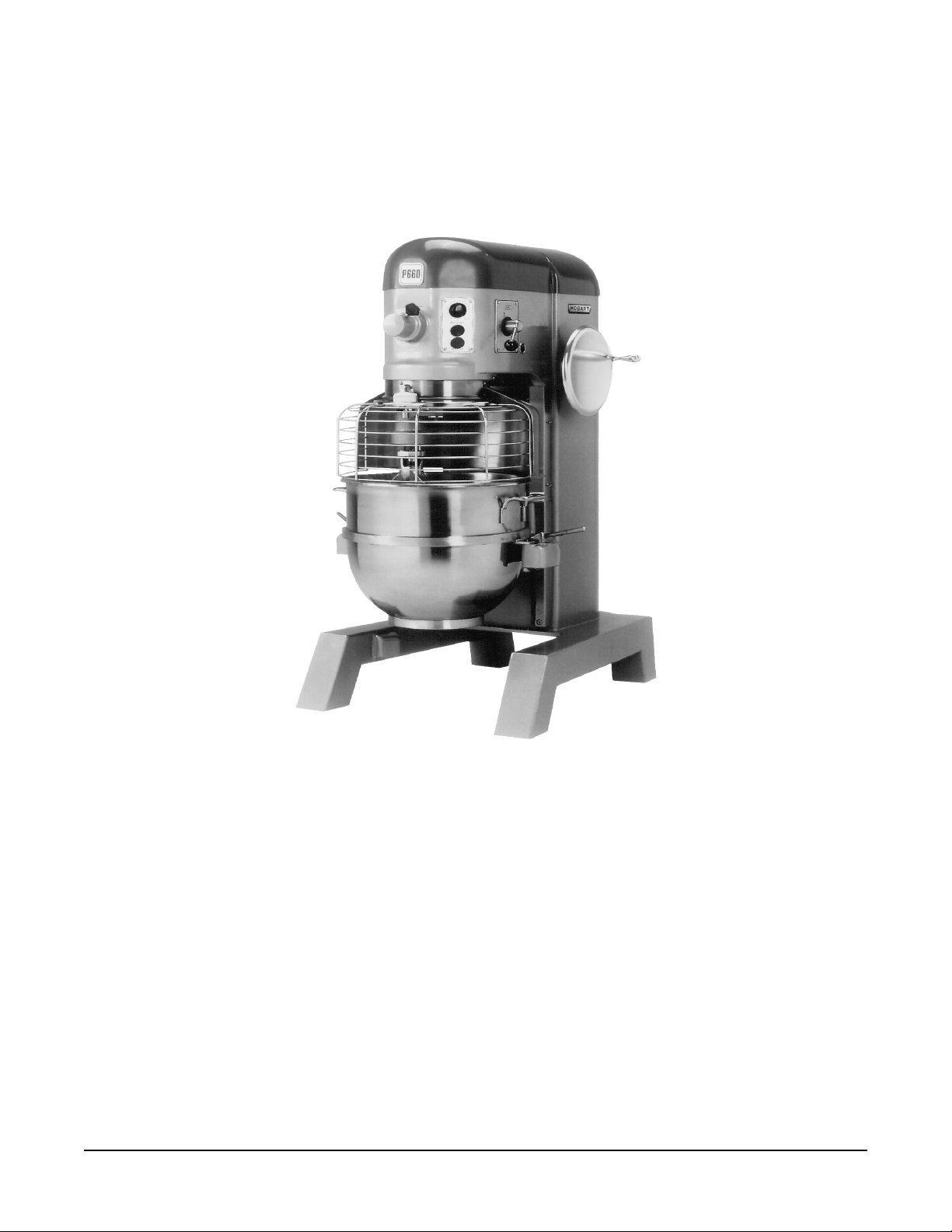
Model P660CE Mixer (two speed shown)
Shipping Weight: 399 kg (880 lb)
Net Weight: 387 kg (853 lb)
– 2 –
© HOBART CORPORATION, 1998
Page 3

TABLE OF CONTENTS
GENERAL................................................................................................................................................ 4
INSTALLATION....................................................................................................................................... 5
Unpacking.......................................................................................................................................... 5
Location ............................................................................................................................................. 5
Check Lubrication Before Use ......................................................................................................... 5
Installation Codes and Standards .................................................................................................... 6
Electrical Connections ...................................................................................................................... 6
OPERATION ........................................................................................................................................... 7
Electromechanical Timer Controls ................................................................................................... 7
Changing speeds (Two-speed Model) ............................................................................................. 8
Bowl Lift ............................................................................................................................................. 8
Mixing................................................................................................................................................. 8
Bowl Guard (Before September 2002 Production Fig. 6)............................................................... 9
Wire Cage assembly (After September, 2002 Production Fig. 7)................................................ 10
Attachments .................................................................................................................................... 12
Mixer Speeds (When Equipped) .................................................................................................... 12
CLEANING ............................................................................................................................................ 13
MAINTENANCE .................................................................................................................................... 14
Lubrication ....................................................................................................................................... 14
Adjustments..................................................................................................................................... 15
TROUBLESHOOTING .......................................................................................................................... 16
SERVICE ............................................................................................................................................... 16
– 3 –
Page 4

Installation, Operation, and Care of
P660CE MIXERS
SAVE THESE INSTRUCTIONS
GENERAL
The P660CE model mixer is a heavy duty 60-quart mixer which is designed primarily for preparing
dough, batter, and pastry. It is available with a single-speed or two-speed transmission and features
1
/2 horsepower Hobart-designed motor, a #12 Attachment Hub and an electromechanical timer as
a 2
standard equipment.
A 60-quart, stainless steel mixer bowl and a 60-quart, burnished aluminum, ED style dough arm are
furnished with each mixer.
Bowl Guard is standard equipment on all P660CE models.
The single-speed and the two-speed mixer have painted finishes.
– 4 –
Page 5
INSTALLATION
UNPACKING
Immediately after unpacking the mixer, check for possible shipping damage. If this machine is found
to be damaged after unpacking, save the packaging material and contact the carrier within 15 days of
delivery.
Prior to installation, test the electrical service to ensure that it agrees with the specifications on the
machine data plate.
LOCATION
Place the mixer in its operating location. There should be adequate space around the mixer for the user
to operate the controls and install and remove bowls. The area above the mixer should allow the top
cover to be removed for routine maintenance and servicing.
Holes are provided in the base for permanent bolting to the floor; although this is not necessary in
normal installations. Four plastic plugs are supplied with the mixer to plug these holes if they are not
used.
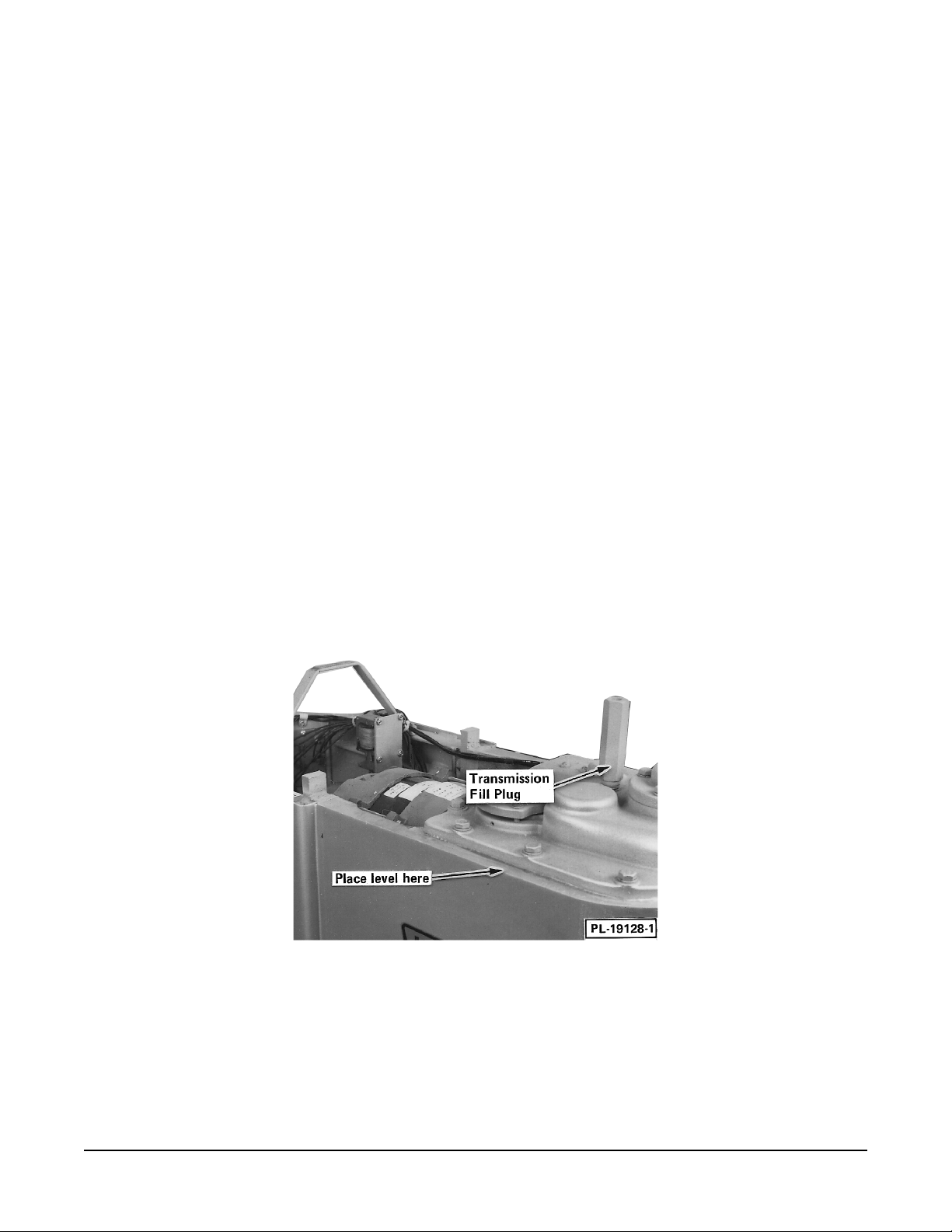
Once located, the mixer must be leveled.
• Remove the top cover screws and the top cover.
• Place a level on the machined surface of the transmission case (Fig. 1) and slide shims under
the legs (base) of the mixer as required to level it front-to-back and side-to-side.
• Do not replace the top cover until installation is completed.
Fig. 1
CHECK LUBRICATION BEFORE USE
This mixer is shipped with oil in the transmission. Mixers produced prior to September 2002 will have
oil in the planetary. Mixers produced after September 2002 will have grease in the planetary. Check
oil levels before starting mixer. Refer to Lubrication, page 14, for applicable lubrication procedures.
– 5 –
Page 6

INSTALLATION CODES AND STANDARDS
The installation of this mixer must be carried out by a licensed installer and in accordance with the
applicable regulations, standards, codes of practice and related publications of the country of
destination.
ELECTRICAL CONNECTIONS
WARNING: ELECTRICAL AND GROUNDING CONNECTIONS MUST COMPLY WITH THE
APPLICABLE PORTIONS OF RELEVANT ELECTRICAL CODES.
WARNING: MODEL P660CE MIXER (SINGLE SPEED SHOWN) DISCONNECT ELECTRICAL
POWER SUPPLY AND PLACE A TAG AT THE DISCONNECT SWITCH INDICATING THAT YOU ARE
WORKING ON THE CIRCUIT.
ELECTRICAL DATA
MODEL Volts / Hz / Ph RATED AMPS
P660CE 400 / 50 / 3 4
A 26 mm hole for installation of the electrical conduit is located at the top of the pedestal. Make the
electrical connections per the wiring diagram located on the inside of the Top Cover.
Check Rotation
Three-phase machines must be connected so the planetary rotates in the direction of the arrow on the
Drip Cup. To check rotation:
• Set the gear shift lever on 1 (two speed model).
• Apply power to the mixer and set the Electromechanical Timer on HOLD. With the Bowl Support
all the way up, momentarily run the machine by pushing the START and then STOP buttons.
• If rotation is incorrect, DISCONNECT ELECTRICAL POWER SUPPLY and interchange any
two of the incoming power supply leads.
– 6 –
Page 7

OPERATION
WARNING: MOVING BEATER IN BOWL, KEEP HANDS, CLOTHING, AND UTENSILS OUT WHILE
IN OPERATION, DO NOT USE WITHOUT INTERLOCKED GUARD.
The P660CE mixer is equipped with an Electromechanical Timer Control (described at the bottom of
this page). Also, become familiar with the other operating parts (Fig. 2) and their functions, which are
referenced throughout the Operation section.
The Bowl Guard must be in position or the mixer will not operate. Refer to page 9.
If the Bowl Support is not all the way up, the mixer will not operate unless the START button is held
in.
Fig. 2 Fig. 3
ELECTROMECHANICAL TIMER CONTROLS
The START button is used to start the mixer.
The STOP button is used to stop the mixer.
The TIMER is used in conjunction with the START button
for timed mixing operations and will stop the mixer when a
preset time has elapsed.
– 7 –
Two-speed model only
Fig. 4
Page 8

CHANGING SPEEDS (TWO-SPEED MODEL)
Models with a two-speed selection use the Shift Lever to change speeds. Always stop the mixer before
changing speeds.
To Change Speeds
1. Push the STOP button.
2. Move the Shift Lever to the desired
speed.
3. Restart the mixer by pushing the
STARTbutton.
NOTE: If you do not stop the mixer before
changing speeds, the mixer will automatically
shut itself off and will have to be restarted
after changing speeds.
BOWL LIFT
Fig. 5
PL-41266
The Hand wheel is used to raise and lower the bowl on mixers with the standard bowl lift. Turn the Hand
wheel clockwise to raise the bowl or counterclockwise to lower it.
MIXING
This section explains operation of the mixer and how to install bowls and agitators.
Bowl
New mixer bowls and agitators (beaters, whips, and dough arms) should be thoroughly washed with
hot water and a mild soap solution, rinsed with either a mild soda or vinegar solution and thoroughly
rinsed with clear water BEFORE being used.
The bowl must be installed before the agitator.
To install the bowl, fully lower the bowl support. Position the bowl so the alignment bracket on the back
of the bowl is under the retainer on the bowl support and the alignment pins on the front of the bowl
support fit in the holes in the bowl. Lock the bowl in place by rotating the bowl clamps over the ears
of the bowl.
If a bowl adapter is required, install it on the bowl support as you would the bowl and then install the
bowl on the adapter.
Agitator
To install an agitator, the bowl must be installed and fully lowered. Place the agitator in the bowl, push
it up on the agitator shaft and turn it clockwise to seat the shaft pin in the slot of the agitator shank.
Raising the Bowl While Mixing
To raise the bowl while the agitator is mixing the product (when required by recipe): Load ingredients.
Close Wire Cage assembly. To begin mixing, press and hold the Start button; then raise the bowl.
– 8 –
Page 9

BOWL GUARD (BEFORE SEPTEMBER 2002 PRODUCTION FIG. 6)
The Wire Cage assembly on the Bowl Guard can be rotated out of the way to add ingredients or access
the bowl and agitator. Some ingredients, such as liquids or powders, may be added through the Wire
Cage assembly while the mixer is in operation. An ingredient chute accessory is available to assist in
adding ingredients. Contact your local Hobart Sales representative for more information.
Rotating the Wire Cage assembly to the Rear
Push the Latch in to release the Centering Pin from the Centering Ramp. Note how the grooves on
the nylon Retainers allow the Wire Cage to ride around the circular Ridge of the planetary Drip Cup.
The Wire Cage can rotate 360° left or right. When the Wire Cage returns to the front and center
position, the Centering Pin is captured and held by the Centering Ramp, restricting rotation of the Wire
Cage until the Latch is pressed again.
The Wire Cage must be in the front-center position for the mixer to operate.
Removing the Wire Cage assembly for Cleaning
Lower the Bowl. Rotate the Wire Cage to the rear. Remove both Agitator and Bowl. Return the Wire
Cage to the front.
While holding the Wire Cage securely with both hands, use your thumb to push down on the Black
Release Knob. Lower and remove the Wire Cage. Wash it in a sink, rinse with clear water and dry with
a clean cloth.
The stainless steel Splash Guard can be wiped-off or washed easily with a cloth or sponge and warm
soapy water. Rinse with clear water. Dry with a clean cloth.
Reinstalling the Wire Cage Assembly
Hold the Wire Cage so its top ring is positioned around the planetary Drip Cup with the grooves in both
nylon Rear Retainers straddling the Ridge on the Drip Cup. Push in the Front-Center Retainer until
it stays in and so that its grooves also straddle the Ridge on the Drip Cup. The Wire Cage is properly
assembled when all three Retainers straddle the Ridge on the Drip Cup in the three opposed locations.
Rotate the Wire Cage out-of-the-way to install or remove the Agitator and Bowl or to add ingredients.
Return the Wire Cage to its front and center position to operate the mixer.
Fig. 6
– 9 –
Page 10

WIRE CAGE ASSEMBLY (AFTER SEPTEMBER, 2002 PRODUCTION FIG. 7)
The Wire Cage assembly can be rotated out of the way to add ingredients or to access the bowl and
agitator.
Note how the grooves on the nylon retainer shoes allow the wire cage to ride around the Circular Ridge
of the Planetary Drip Cup.
• To open the Wire Cage assembly, rotate it to your left.
• To close the Wire Cage assembly, rotate it to your right until it stops in the Front-Center Position.
NOTE: The Wire Cage assembly must be returned to the Front-Center Position for the mixer to
operate.
Fig. 7
– 10 –
Page 11

Remove Wire Cage Assembly (Fig. 8)
1. Lower the bowl. Remove the accessory and bowl.
2. While holding the wire cage securely with both hands, rotate it to your left until the front-center
retainer shoe reaches the gap in the circular ridge on the planetary drip cup.
3. Lower the front of the wire cage and move the wire cage assembly slightly to the rear so the rear
retainer shoes clear the ridge of the drip cup. The Wire Cage assembly can now be removed.
Fig. 8
4. Wash the Wire Cage assembly in a sink, rinse with clear water and dry with a clean cloth.
5. The stainless steel Splash Guard can be wiped off and/or washed with a cloth or sponge using
warm, soapy water. Rinse with clear water and dry with a clean cloth.
Reinstall Wire Cage Assembly
1. Position the ring of the Wire Cage assembly so the Front-Center Retainer Shoe is lined up with
the gap in the Circular Ridge on the Planetary Drip Cup.
2. Position the grooves so the rear retainer shoes straddle the Circular Ridge on the Planetary Drip
Cup.
3. Lift the front of the Wire Cage assembly so the Front-Center Retainer Shoe passes up through
the gap in the Circular Ridge on the Planetary Drip Cup.
4. Rotate the Wire Cage assembly to your right until all three retainer shoes straddle the ridge on
the Drip Cup in the three opposed locations.
5. Continue rotating the Wire Cage assembly so the opening is to the front of the mixer (to install
the accessory) or until it stops at the Front-Center Position (Fig 8).
– 11 –
Page 12

ATTACHMENTS
To install an attachment, loosen the attachment hub thumb screw and remove the plug. Insert the
attachment into the Attachment Hub, making certain that the square shank of the attachment is in the
square driver of the mixer. Secure the attachment by tightening the thumb screw.
Move the Gear Shift Lever to the desired speed. With the Bowl Support all the way up and the wire cage
in the Front-Center Position, start the mixer to operate the attachment.
The meat and food chopper attachment should be operated in second or third speed. If material in the
cylinder stalls the mixer, push the STOP button at once. Do not attempt to restart the mixer in a lower
speed — remove the adjusting ring, knife, plate and worm and clear any obstruction.
NOTE: This attachment must not be used to chop bread crumbs.
NOTE: Attachment Hub should not be used while mixing.
Bowl Scraper Attachment
The Mixer Bowl Scraper Attachment (when ordered) is provided with a separate instruction manual
covering its installation, operation, use and care.
MIXER SPEEDS (WHEN EQUIPPED)
Speed 1 (Low) — This speed is for heavy mixtures such as pizza dough, heavy batters and potatoes.
Speed 2 (Medium-low) — This speed is for mixing cake batters, mashing potatoes and developing
bread dough.
Speed 3 (Medium-high) — This speed is for incorporating air into light batches, as well as finishing
whipped items.
Speed 4 (High) — This speed is for maximum and accelerated air incorporation into light batches.
– 12 –
Page 13

CLEANING
WARNING: DISCONNECT ELECTRICAL POWER SUPPLY AND PLACE A TAG AT THE
DISCONNECT SWITCH INDICATING THAT YOU ARE WORKING ON THE CIRCUIT BEFORE
BEGINNING ANY CLEANING PROCEDURE.
A flat scraper is furnished to aid in cleaning bowls and agitators.
The mixer should be thoroughly cleaned daily. DO NOT use a hose to clean the mixer — it should be
washed with a clean damp cloth. The base allows ample room for cleaning under the mixer. The apron
may be removed by loosening the thumb screws. Behind this apron is an access cover which may be
removed for cleaning.
The Drip Cup-Splash Guard (which is secured by three screws) should be removed periodically and
wiped clean.
For cleaning the Bowl Guard (including both Wire Cage assembly and Splash Guard), refer to
page 9.
– 13 –
Page 14

MAINTENANCE
WARNING: DISCONNECT ELECTRICAL POWER SUPPLY AND PLACE A TAG AT THE DISCONNECT
SWITCH INDICATING THAT YOU ARE WORKING ON THE CIRCUIT BEFORE BEGINNING ANY
MAINTENANCE PROCEDURE.
LUBRICATION
Planetary (Before September, 2002 Production)
The planetary oil should be checked periodically. To check, DISCONNECT ELECTRICAL POWER
SUPPLY and remove the Drip Cup-Splash Guard, which is secured by three screws. Remove the fill
plug (Fig. 9). Oil should be even with the bottom of the fill-plug hole. If it is not, slowly add the
recommended planetary lubricant until it is. Replace the fill plug and the Drip Cup-Splash Guard.
A drain plug (Fig. 9) is located on the bottom of the planetary. Should draining become necessary,
remove the Drip Cup-Splash Guard and place a suitable catch pan under the drain plug. Remove the
drain plug, allow the oil to completely drain and replace the drain plug. Remove the fill plug and pour
in 177 ml (6 fluid ounces) of the recommended planetary lubricant. Replace the Fill Plug and the Drip
Cup-Splash Guard. Contact your local Hobart service office for the recommended planetary lubricant.
Planetary (After September, 2002 Production)
Mixers produced after September, 2002 have a grease-filled planetary and do not require routine
lubrication maintenance.
Fig. 9 Fig. 10
Planetary Seal
Occasionally, the planetary seal (Fig. 9) may become dry and begin to squeak. To correct this, work
a little lubrication under the lip of the seal.
Transmission
The transmission oil should be even with the line on the oil level gauge when the motor is NOT running.
If the oil falls below this line, DISCONNECT ELECTRICAL POWER SUPPLY and remove the Top
Cover, which is secured by two screws. Remove the Transmission Fill Plug (Fig.10) and add a small
amount of the recommended transmission oil until it returns to the proper level. DO NOT overfill the
transmission as leakage may result. Contact your local Hobart service office for the recommended
transmission oil: Mobilgear 634 (quantity 3785 ml = 128 fluid ounces).
– 14 –
Page 15

Bowl Lift
The slideways and lift screw (Fig. 9) should be lubricated approximately twice a year. To reach these
areas, fully lower the bowl support and remove the apron, which is secured by four thumb screws. Wipe
a thin coat of Lubriplate 630AA (supplied) on the bowl clamp area of the bowl supports, each slideway,
and the lift screw. Replace the apron.
On units with a manual bowl lift, the Hand wheel gearing should be lubricated periodically. To do this,
DISCONNECT ELECTRICAL POWER SUPPLY and remove the top cover, which is secured by two
screws. Wipe a coat of Lubriplate 630AA on the gear teeth and replace the top cover.
ADJUSTMENTS
Agitator Clearance
The agitator clearance should be checked with each bowl change. The agitator must not touch the
bowl and the maximum clearance between the bottom of the bowl and the E or ED Dough Arm is
5
8 mm (
/16").
Install a Bowl and Agitator. If the Bowl and Agitator come into contact before the Bowl Support reaches
its stop, adjust the Stop Screw upwards following the procedure below.
Measuring the Clearance
Pour enough flour in the bowl to cover the bottom of the bowl where the agitator travels. With the bowl
fully raised, briefly run the mixer.
Turn off the mixer, DISCONNECT ELECTRICAL POWER SUPPLY, and measure the depth of flour
where the agitator has traced a path. This measurement should be taken at several points around the
bowl to assure accuracy.
Adjusting the Bowl/Agitator Clearance
• Remove the Apron (which is secured by 4 thumbscrews).
• Loosen the bottom Locking Nut and turn the Stop Screw counterclockwise to increase the
clearance or clockwise to decrease the clearance.
• Tighten the Locking Nut while holding the Stop Screw.
Bowl Clamps
The height of the bowl clamp is controlled by a spring washer and lock nut, which are located on the
bottom of the bowl support. Turning the lock nut clockwise will loosen the clamp, turning counterclockwise
will tighten it. If repeated adjustments are necessary, additional service is indicated. Contact your local
Hobart service office.
– 15 –
Page 16

TROUBLESHOOTING
SYMPTOMS POSSIBLE CAUSES
Mixer will not start. 1. Circuit protector in open position — check fuse
or disconnect switch.
2. Mixer or attachment overloaded.
3. Bowl not all the way up.
4. Wire Cage assembly is not in the Front-Center
position.
Agitator touches bowl. 1. Bowl Clamp(s) not closed.
2. Improper agitator clearance — see MAINTENANCE
for adjustment procedure.
3. Bowl Clamp(s) improperly adjusted — see
MAINTENANCE for adjustment procedure.
Planetary seal squeaks. Seal requires occasional lubrication — see MAINTENANCE.
SERVICE
If service is needed on this equipment, contact your local Hobart service office.
Our Hobart trained service technicians strategically located at the many Hobart branches are prepared
to give you fast, efficient and reliable service. Protect your investment by having a Hobart inspection
contract which assures the continued, efficient operation of your Hobart machines, spares and
accessories.
For further details, contact your local regional office:
London & Home Counties 01234 841220
Scotland & N. Ireland 0141 7743456
Midland & Wales 0121 7898228
Southern 01454 616048
Northern 0113 2759727
The Hobart Manufacturing Company Limited
Hobart House
51 The Bourne Telephone: 0181 920 2800 Fax: 0181 886 0450
Southgate
London N14 6RT
F-23196 Rev. A (Apr. 2003) PRINTED IN THE U.S.A.
– 16 –
 Loading...