


P660 MIXERS
ML-134198, 134199, 134200
P660 MIXER
701 S. RIDGE AVENUE
TROY, OHIO 45374-0001
937 332-3000
www.hobartcorp.com
F-34818 Rev. B (Apr. 2003)
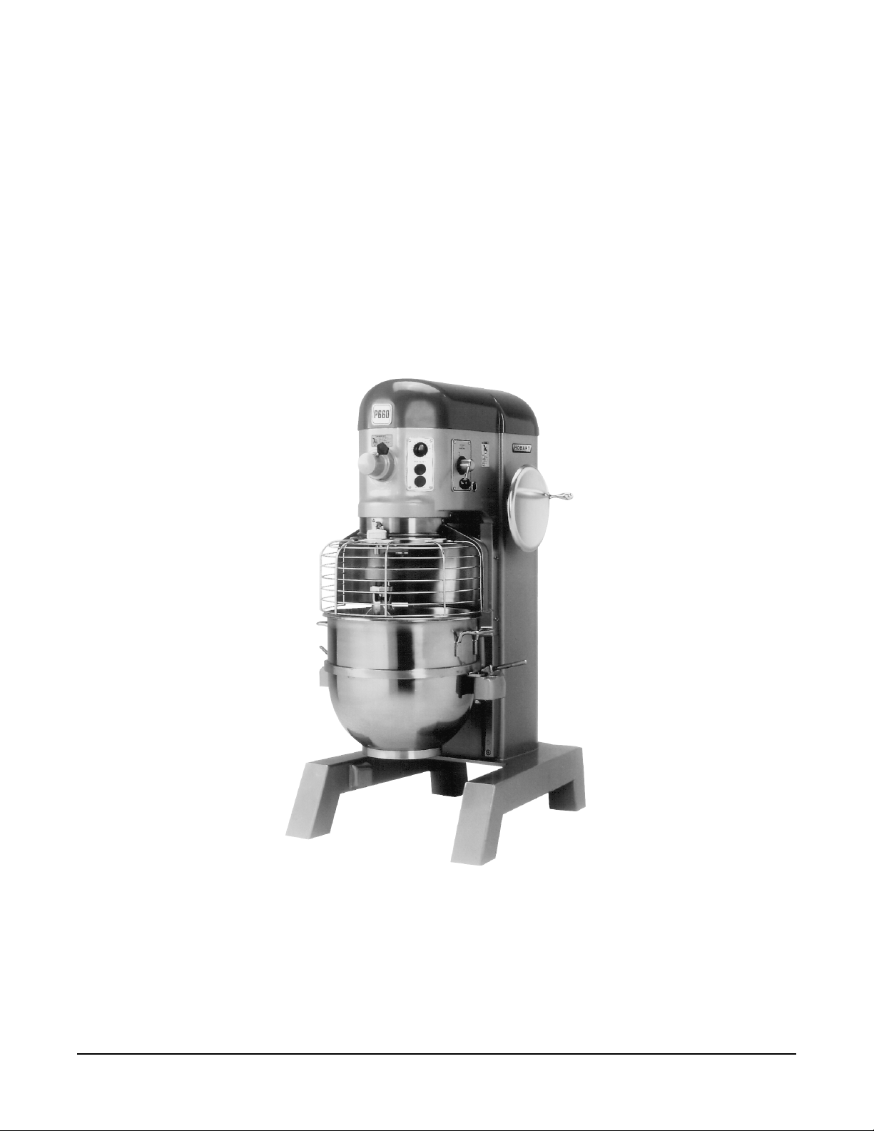
Model P660 Mixer
© HOBART CORPORATION, 2002
– 2 –

TABLE OF CONTENTS
GENERAL............................................................................................................................................. 4
INSTALLATION.................................................................................................................................... 5
Unpacking....................................................................................................................................... 5
Location .......................................................................................................................................... 5
Electrical Connections ................................................................................................................... 6
Electrical Data ................................................................................................................................6
OPERATION ........................................................................................................................................ 7
Electromechanical Timer Controls (When Equipped).................................................................. 7
Programmable Timer Controller (When Equipped) ..................................................................... 8
Changing Speeds......................................................................................................................... 11
Bowl Lift ........................................................................................................................................ 11
Mixing............................................................................................................................................ 11
Wire Cage assembly (Before September, 2002 Production Fig. 5) ......................................... 12
Wire Cage assembly (After September, 2002 Production Fig. 6)............................................. 13
Attachments ................................................................................................................................. 15
Mixer Speeds (When Equipped) ................................................................................................. 15
CLEANING ......................................................................................................................................... 15
MAINTENANCE ................................................................................................................................. 16
Lubrication .................................................................................................................................... 16
Adjustments.................................................................................................................................. 18
TROUBLESHOOTING ....................................................................................................................... 19
Service .......................................................................................................................................... 19
– 3 –

2345678901234567890123456789012123456789
0
0
0
0
0
0
0
0
0
0
0
0
0
0
0
0
0
0
0
0
0
0
0
0
0
0
0
0
0
0
0
0
0
2345678901234567890123456789012123456789
2345678901234567890123456789012123456789
2345678901234567890123456789012123456789
2345678901234567890123456789012123456789
2345678901234567890123456789012123456789
2345678901234567890123456789012123456789
2345678901234567890123456789012123456789
2345678901234567890123456789012123456789
2345678901234567890123456789012123456789
2345678901234567890123456789012123456789
2345678901234567890123456789012123456789
2345678901234567890123456789012123456789
2345678901234567890123456789012123456789
2345678901234567890123456789012123456789
2345678901234567890123456789012123456789
2345678901234567890123456789012123456789
2345678901234567890123456789012123456789
2345678901234567890123456789012123456789
2345678901234567890123456789012123456789
2345678901234567890123456789012123456789
2345678901234567890123456789012123456789
2345678901234567890123456789012123456789
2345678901234567890123456789012123456789
2345678901234567890123456789012123456789
2345678901234567890123456789012123456789
2345678901234567890123456789012123456789
2345678901234567890123456789012123456789
2345678901234567890123456789012123456789
2345678901234567890123456789012123456789
The P660 model mixer is a heavy-duty, 60-quart mixer which is designed primarily for preparing dough,
2345678901234567890123456789012123456789
2345678901234567890123456789012123456789
batter and pastry. It features a 2
2345678901234567890123456789012123456789
Installation, Operation and Care of
P660 MIXERS
SAVE THESE INSTRUCTIONS
GENERAL
1
/2 horsepower Hobart-built motor, a #12 Attachment Hub and an
electromechanical timer as standard equipment.
Also available are the following: 30-, 40- or 60-quart bowls, bowl adapters, special agitators and a
variety of other accessories and attachments. These are described in a separate
Handbook,
which is furnished with each mixer.
Use and Applications
Bowl Guard is standard equipment on all P660 models.
Programmable timer controller is optional on P660 models.
– 4 –
INSTALLATION
UNPACKING
Immediately after unpacking the mixer, check for possible shipping damage. If this machine is found
to be damaged after unpacking, save the packaging material and contact the carrier within 15 days of
delivery.
Prior to installation, test the electrical service to make sure that it agrees with the specifications on the
machine data plate.
LOCATION
Place the mixer in its operating location. There should be adequate space around the mixer for the user
to operate the controls and to install and remove bowls. The area above the mixer should allow the top
cover to be removed for routine maintenance and servicing.
Holes are provided in the base for permanent bolting to the floor; although this is not necessary in
normal installations. Four plastic plugs are supplied with the mixer to plug these holes if they are not
used.
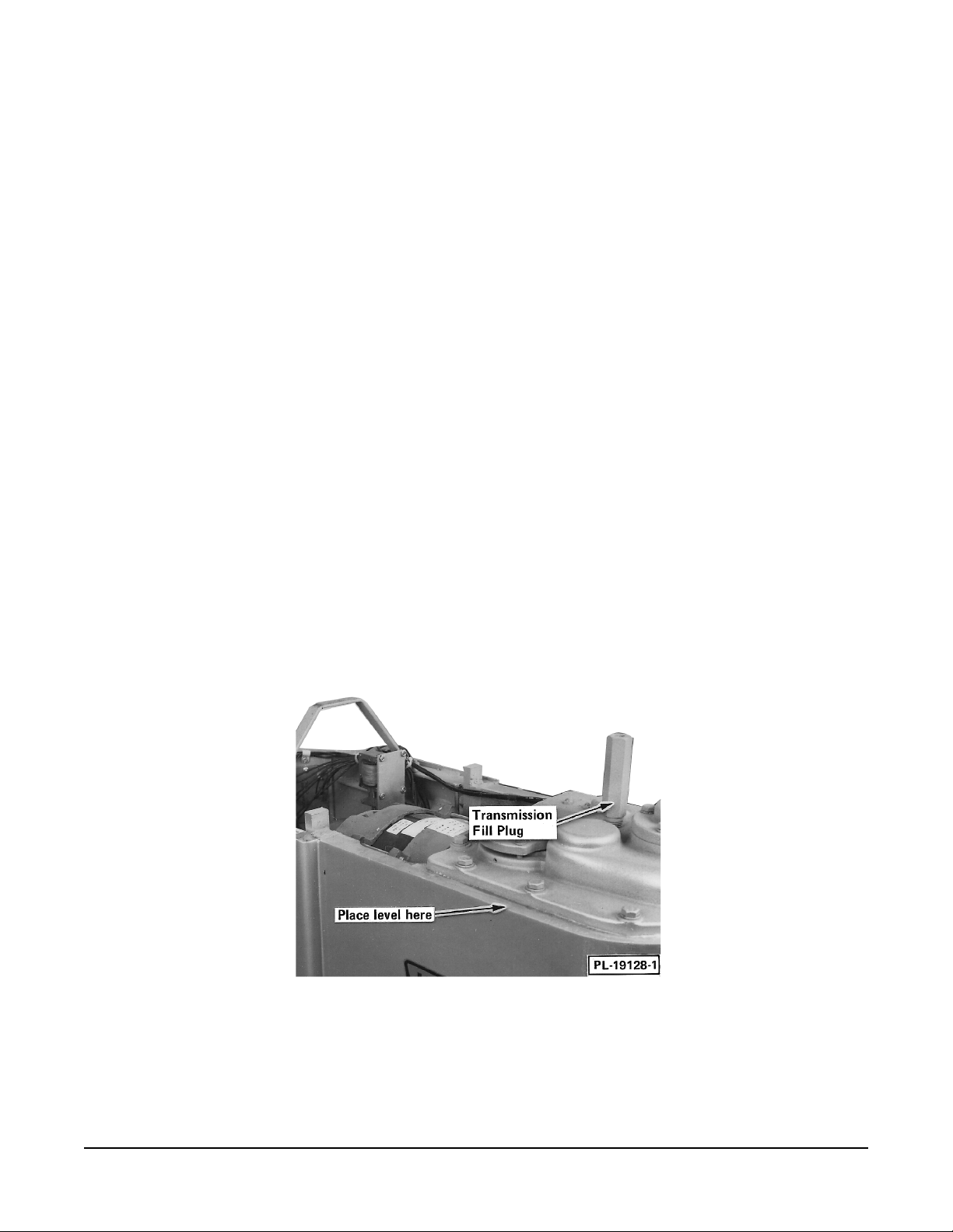
Once placed in the operating location, level the mixer.
1. Remove the top cover screws and the top cover.
2. Place a level on the machined surface of the transmission case (Fig. 1).
3. Slide shims under the legs (base) of the mixer as required to level it front-to-back and side-toside.
NOTE: Do not replace the top cover until installation is complete.
Fig. 1
Check Lubrication Before Use
This mixer is shipped with oil in the transmission. Mixer production prior to September 2002 will have
oil in the planetary. Mixer production after September 2002 will have grease in the planetary. Check
oil levels before starting mixer. Refer to Lubrication, pages 16 to 17, for applicable lubrication
procedures.
– 5 –

ELECTRICAL CONNECTIONS
WARNING: ELECTRICAL AND GROUNDING CONNECTIONS MUST COMPLY WITH THE
APPLICABLE PORTION OF THE NATIONAL ELECTRICAL CODE AND/OR OTHER LOCAL
ELECTRICAL CODES.
WARNING: DISCONNECT THE ELECTRICAL POWER TO THE MACHINE AND FOLLOW
LOCKOUT / TAGOUT PROCEDURES.
ELECTRICAL DATA
C°06
reppoC
erIW
eziS
tnemelElauD*
esuFyaleD-emiT
tiucriC
eziS
)spmA(
**rekaerBtiucriC
)spmA(
C°06
reppoC
eziSeriW
rekaerBtiucriCemiTesrevnI**
sledoM hP/zH/stloV
066P1/06/8020.02030301030321
066P1/06/0420.71525201030301
066P3/06/042/8026.8515141020221
A hole for
detaR
spmA
3
/4" trade size conduit is located at the top of the pedestal. Make electrical connections per
tiucriC
eziS
)spmA(
*esuF
eziS
)spmA(
the wiring diagram located on the inside of the Top Cover.
Check Rotation (Three-Phase Machines Only)
Three-phase machines must be connected so the planetary rotates in the direction of the arrow on the
Drip Cup. To check rotation:
1. Set the Gear Shift Lever on 1.
2. Apply power to the mixer, set the electromechanical timer on HOLD or, if equipped with a
programmable timer controller, set it on [ -- : -- ]. With the Bowl Support all the way up,
momentarily run the machine by pushing the START and then STOP buttons.
3. If rotation is incorrect, disconnect electrical power supply and interchange any two of the
incoming power supply leads.
– 6 –
 Loading...