

Page 1
INSTALLATION AND
OPERATION INSTRUCTIONS
(original instructions)
V1.6 2012.09.04
ECOMAX 502L(P)
GLASS- AND DISHWASHERS
Page 2

2
IMPORTANT NOTES
THE ORIGINAL INSTRUCTIONS.
ONLY TRAINED OR AUTHORIZED ADULT PERSONS OPERATE THE MACHINES.
USE IN ACCORDANCE WITH REGULATIONS
The machine is technical work equipment for express use in the work place.
The machine is exclusively to be used to wash ware such as plates, cups, glasses, cutlery, trays etc.
Do not use for electrically heated cooking and heat conservation appliances.
SAFETY:
Never hose down the machine.
The “Attention” symbol is shown beside instructions that are essential for the safe operation of the
machine.
Please read these passages thoroughly.
LIABILITY:
Installations and repairs which are carried out by non-authorized technicians or the use of other than
original spare parts, and any technical alterations to the machine, may affect the warranty set
out in the standard conditions of sale.
The machine can be used by one person only, does not allow two or more people operate at the same time.
MACHINE NOISE LEVEL:
The machine noise level is ≤ 70 dB (A).
USING ENVIRONMENT
Electric equipment shall be capable of operating correctly in the intended ambient air temperature. The minimum
requirement for all electrical equipment is correct operation between air temperature of +5℃ and +40℃.
The electrical equipment shall be capable of operating correctly when the relative humidity does not exceed 50% at a
maximum temperatrue of +40℃. Higher relative humidities are permitted at lower temperatures (for example 90% at
20℃).
Electrical equipment shall be capable of operating correctly at altitudes up to 1000m above mean sea level.
The equipment are not used in the potential explosive environment.
CONNECTING TENSIONS:
The machine described in this operation manual has following connecting tensions:
400 V/50 Hz/3 Ph/N/PE or 230 V/50 Hz/1 Ph/N/PE
GENERAL INFORMATION ON WASHING GLASSES AND CUTLERY:
The local supply water quality has a major impact on the wash and rinse result. A high content of minerals which are
dissolved in the water during the drying process may become visible in the form of spots and streaks.
Authorised service personnel can determine the content of minerals by measuring the electrical conductivity. Values of
less than 80 Microsiemens/cm indicate a low content of minerals. Higher contents need to be reduced below the critical
level by demineralising the water using specic demineralisation cartridges or a reverse osmosis system.
Please contact your authorised service partner for support.
We recommend the use of specic glass racks. These racks hold the glasses in slightly inclined positions – this will
Page 3

3
IMPORTANT NOTES
improve the rinse efciency.
To avoid unpleasant smelling glasses, specic chlorine-free detergent for glass washing should be used.
Before washing new glasses the rst time with a commercial glass washer, intensive basic cleaning is mandatory to
reduce the greasy lm which is on most glasses for protection during production. If not, water drainage is impaired and
streaks and spots may remain on glasses.
We recommend carrying out the basic cleaning manually in a sink (using gloves and a brush for cleaning) with a much
higher chemical concentration of detergent (minimum 10 g of detergent per liter).
As continued product improvement is a policy of HOBART, specications are subject to change without notice.
Company address: No.8 Yesheng Road, Xiqing Economic & Development Zone, Tianjin China.
Page 4

4 06.01.2012 BA-21907-001-GB
CONTENTS Page
1. BRIEF INTRODUCTION ................................................5
2. TRANSPORTATION, STORAGE AND INSTALLATIONS .....6
2.1. transportation and storage ...................................................................6
2.2. Location .............................................................................................6
2.3. Electrical connection............................................................................6
2.4. Water connection ................................................................................7
2.5. Drain connection .................................................................................7
3. CONTROLS ................................................................8
4. START-UP ..................................................................9
4.1. Detergent PUMP (OPTIONAL) ................................................................9
4.2. Rinse aid PUMP (OPTIONAL) .................................................................9
4.3. Priming the suction hoses ..................................................................10
4.4. Softener (optional) .............................................................................11
5. OPERATION .............................................................12
5.1. Preparation .......................................................................................12
5.2. Run ..................................................................................................13
6. SWITCH-OFF AND CLEANING THE MACHINE..............14
6.1. Switch-off..........................................................................................14
6.2. Cleaning (daily) ..................................................................................14
6.3. Cleaning (weekly) ...............................................................................14
7. SETTINGS ................................................................15
7.1. Adjustment of detergent dosage quantity .............................................15
7.2. Adjustment of rinse aid dosage quantity ..............................................15
7.3. Adjustment of water hardness ...........................................................16
8. FROST PREVENTION ................................................17
9. MAINTENANCE ........................................................18
10. TROUBLESHOOTING GUIDE ......................................19
10.1. Poor wash result ...............................................................................19
10.2. Other faults .......................................................................................20
10.3. Malfunctions ......................................................................................20
Page 5
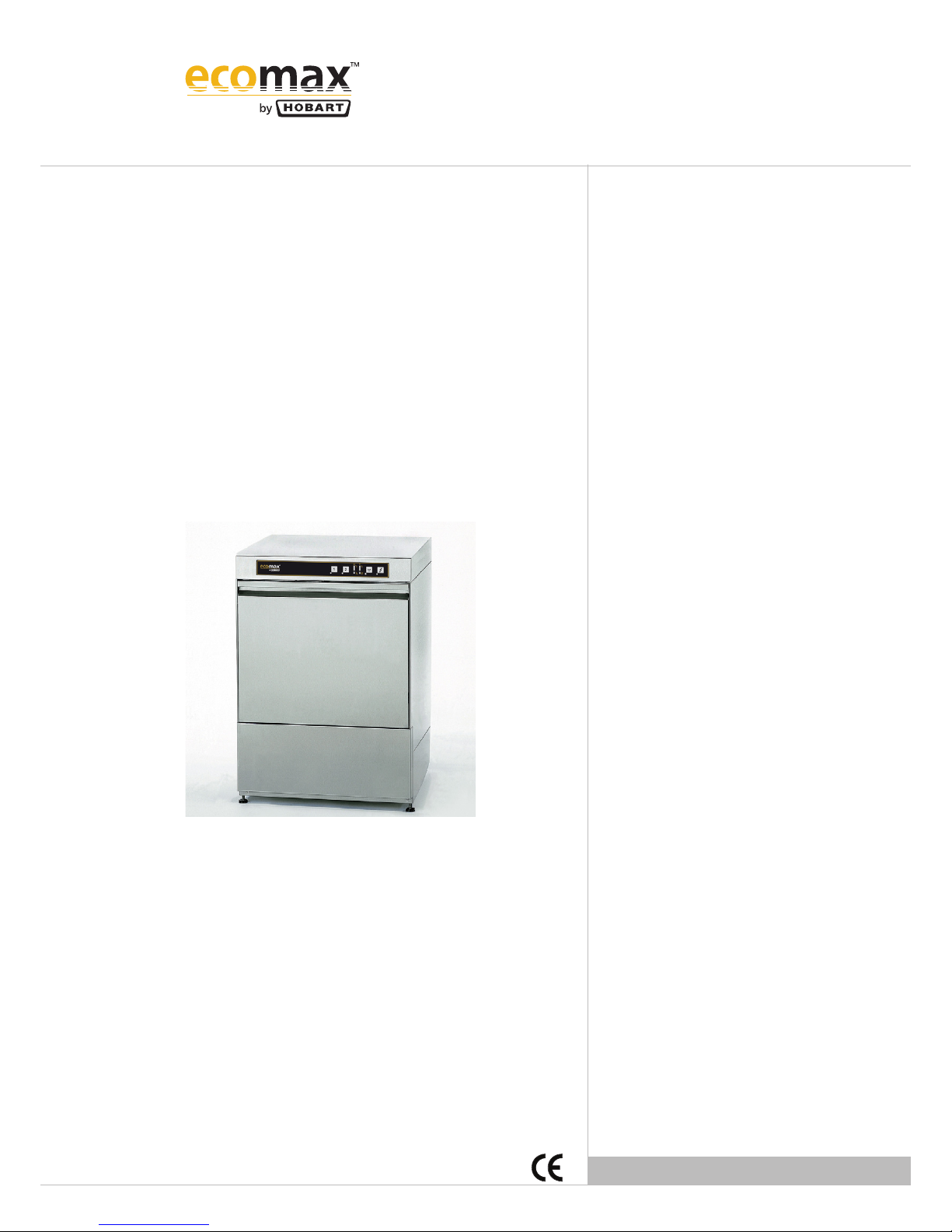
1. BRIEF INTRODUCTION
Introduction table:
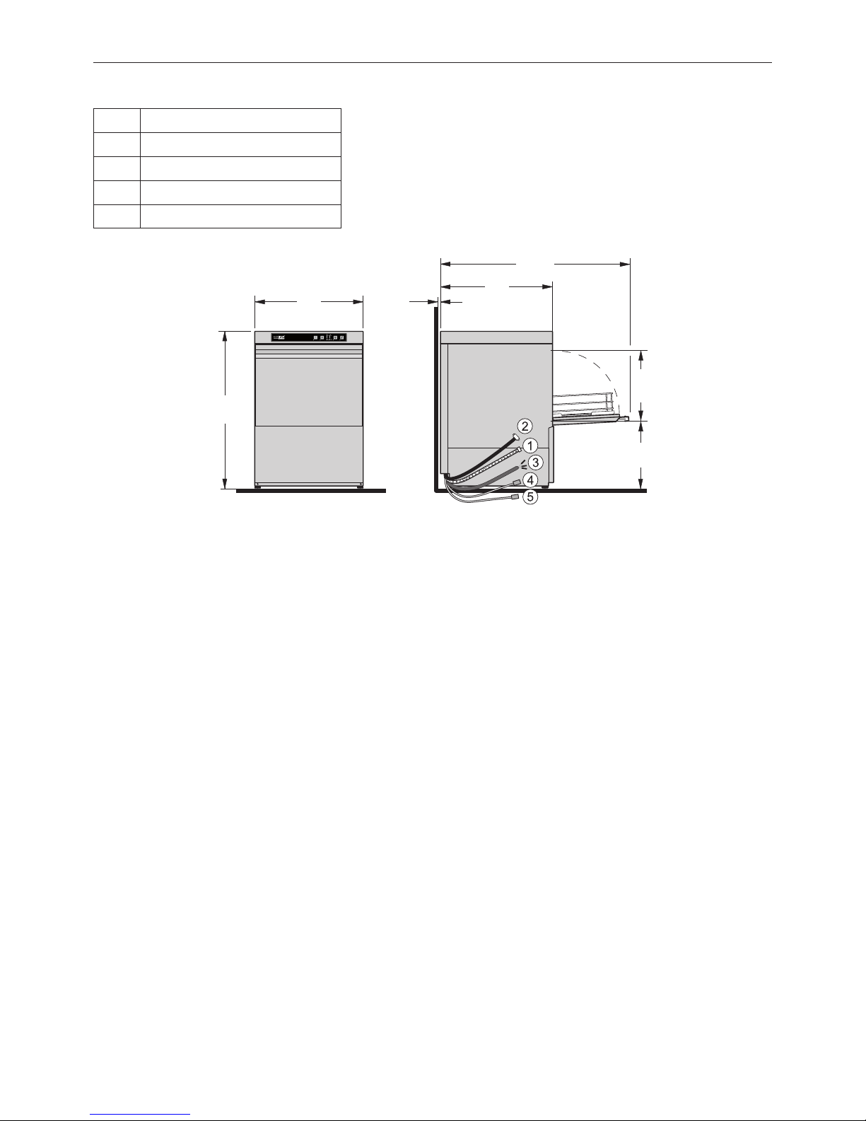
1 Filling connection G3/4
2 Tank drain DN20
3 Power line
4 Detergent dosage
5 Rinse aid dosage
575
790
356
600
960
316
5
Page 6

6
2. TRANSPORTATION, STORAGE AND INSTALLATIONS
2.1. TRANSPORTATION AND STORAGE
Folklift must be used during transportation and storage instead of vertical
loading, pay attention to upturn and prevention of break, moisture and
load. (See the marks on the package).
2.2. LOCATION
– Rear wall clearance not required.
– Level machine by turning the feet.
– Distribute machine weight equally onto all feet
2.3. ELECTRICAL CONNECTION
Must be carried out by an authorized technician according to
the local and national codes.
– The electrical supply shall comply with the name-plate data.
– Line fuses and cable cross section shall comply with the
requirements.
NOTE: The machine with or without interlock function has different
working current. Please refer to the wiring diagram.
NOTE: A cut-off device shall be provided to connect the supply cord
(isolating switch or accessible plug device).According to EN
60 335 the appliance must be connected to an equipotential
conductor. The connecting screw ( ) is located beside the
cable inlet.
Page 7
7
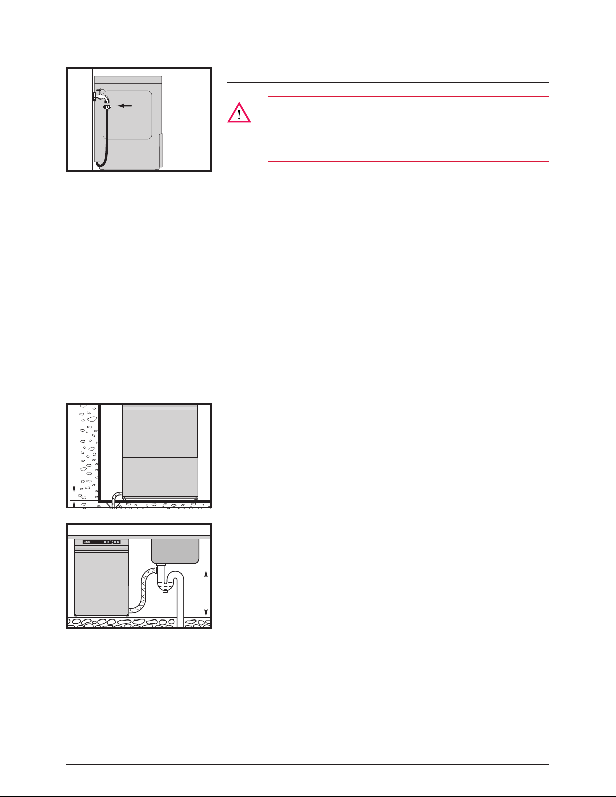
2.4. WATER CONNECTION
Must be carried out by an authorized technician according to
the national and local codes.
The machine must be operated with potable water. For water
with an extremely high mineral content an external demineralisation is strongly recommended
– Connect to warm water, if possible (max. 65°C).
– Water hardness:
• Machines without softener: max. 3.75° Clark = 0.5 mmol/l.
• Machines with softener: max. 37.5° Clark = 5.3 mmol/l.
– Line ow pressure
Line ow pressure 0,5 – 6 bar.
> 6 bar: pressure reducer valve necessary.
– Connect the union nut “A” (3/4”) of the water supply hose to the
site shut off valve.
– Do not kink or cut the supply hose. If an extended supply hose is
required, use one of the same specications as the original.
NOTE: The water hardness should be ≤0.5mmol/L. If not, water
softener is strongly recommended. Or else, may affect the
warranty set out in the standard conditions of sale.
2.5. DRAIN CONNECTION
Machine without drain pump
– Ensure gravity drain.
– For these machine types, a oor drain is mandatory as the drain
hose exits the machine at approx. 60 mm above oor level. Otherwise, residual water may remain in the tank and hose.
– Do not kink drain hose.
Machine with drain pump
– Connection between machine and site drain must not exceed max.
height of 0,65 m.
– Do not place the drain hose loosely on the oor (the hose could be
rubbed through). Fix it at site!.
– Do not kink drain hose
A
max. 60 mm
max. 0.65 m
2. TRANSPORTATION, STORAGE AND INSTALLATIONS
Page 8

8
1
8
354
76
22
70
65
60
55
50
45
85
80
75
70
65
60
3. CONTROLS
➀
Machine ON/STOP button Pushing this button switches the machine on.
The LED lights up
− ashing = Machine is lling and heating.
− permanent = Maschine is ready to operate.
In case of operating error or faults, it is possible to switch-off the machine immediately without the drain cycle, by pushing this button.
After switch off, the machine is not voltage free!
➁
Program buttons By pushing these buttons, it is possible to select between short cycle (1) and
standard cycle (2).
The appropriate LED lights up.
➂
Drain/OFF button By pushing and holding (3 seconds) this button, the self-cleaning cycle starts.
At the end of the cycle, the machine switches off automatically. Machines with
optional drain pump will drain the tank automatically.
After switch off, the machine is not voltage free!
➃
Temperature indication Wash
➄
Temperature indication Rinse
➅
Salt required Indicating the need for regeneration salt to be added. (Only with built-in soft-
ener.)
➆
Regeneration indicator Softener regeneration active.The cycle running time can extend.
➇
Indicator for setting functions The individual LEDs are also used for various settings and special functions:
Hose priming – rinse aid
Hose priming – detergent
Adjustment of water hardness
Rinse aid dosage quantity
Detergent dosage quantity
20
19
18
17
16
15
14
13
12
11
10
9
8
7
6
5
4
3
2
1
Left display: The LEDs 1 to 6 illuminate according to the selected
function.
Right display: Indicates the adjusted value
Page 9

9
4. START-UP
Attention:
The maximum suction head of the dosing pumps is 1.5 m. Do
not confuse the containers
Use only detergent and rinse aid for commercial applications.
Please pay attention to the manufacturer’s safety instructions.
NOTE: Before changing to a different product type (even from the
same supplier), the suction hoses must be rinsed thoroughly
with fresh water (procedure as described under section
4.3.). Otherwise, the mixing of different types of chemicals
will cause crystallization, which may result in a malfunction
of the dosing pump.
4.1. DETERGENT PUMP (OPTIONAL)
– Do not use any acidic detergent products with the optional built-in
detergent pump! (The ph-value has to be higher than 7.)
– Place the suction hose into the external detergent container.
Fill the suction hose according to chapter section 4.3.
4.2. RINSE AID PUMP (OPTIONAL)
– Place the suction hose (blue marking) into the external rinse aid
container. Fill the suction hose according to chapter section 4.3.
Page 10

10
4.3. PRIMING THE SUCTION HOSES
ATTENTION:
The machine has to be switched off.
– Open the door.
– Push Program buttons ➁ simultaneously.
• LEDs light up.
• In display ➇, the LEDs 1 and 11−20 illuminate (dependent on
basic setting).
– Push Program button “1” repeatedly, until the display LED 3 lights
up.
– Close the door.
– Push Program button “1” again.
• In display ➇ LED 4 lights up.
4.3.1. DETERGENT SUCTION HOSE
– Only with built in detergent pump.
– Push and hold programm ”2”.
• Hose will be lled.
• moving light display ➇ LEDs 15−18
– Releasing the button interrupts hose priming.
4.3.2. RINSE AID SUCTION HOSE
– Push Program button “1” again.
• In display ➇ LED 5 lights up.
– Push and hold Program button “2”.
• hose will be lled.
• moving light display ➇, LEDs 15−18
– Releasing the button interrupts hose priming.
– Termination of hose priming: Open door or do not press any button
for 30 seconds.
4. START-UP
Page 11

11
4.4. SOFTENER (OPTIONAL)
NOTE: For the rst run, the softener has to be lled with regenera-
tion salt and potable water.
Attention:
Filling the salt reservoir with cleaning agent will damage the
water softener.
– Open the door.
– Unscrew the softener lid and ll the softener with 1.5 kg of “Granu-
lar regeneration salt” (do not use salt tablets).
– Fill up the softener with potable water (only at the rst run). Clean
seal and rim of softener lid carefully, before closing the lid.
– Close lid and tighten.
– In order to prevent corrosion it is necessary to remove any salt
residues from tank bottom.
– Adjust the water hardness according to section 7.3.
When the Salt indicator ➅ ashes during operation, the softener
has to be relled with regeneration salt.
There will be a slight delay before salt light goes out after rell.
4. START-UP
Page 12

12
5.1. PREPARATION
– Check correct position of wash/rinse arms, strainer and overow
pipe.
– Open shut-off valve.
– Switch on main switch or put the plug in.
– Check level of detergent and rinse aid containers.
– Close door and push the ON button
➀
• tank will be lled.
• The button LED ashes during ll and heating cycle. This pro-
cess can take several minutes.
• When the LED changes to steady burning light, machine is ready
for operation.
– Place glasses and cups face downwards into the rack.
– Remove any food debris before loading plates into rack.
– Spray off greasy food leftovers.
If dishes are placed incorrectly, dishes may be not washed
cleanly.
Total weight of dishes and rack should be less than 25kg, and should
be placed steadily in the direction of operation to prevent human body
from injury caused by falling.
5. OPERATION
Page 13

13
5. OPERATION
5.2. RUN
– Put rack into the machine and close the door.
– Start the desired program by selecting the program button 1 or 2
Button "1" = Short cycle
Button "2" = Standard cycle
• The Program button LED ashes, wash cycle is running.
• As soon as the LED changes to steady light, the wash cycle is
nished.
– Open the door and take out rack.
– Allow dishes to dry for 1 minute approx.
– Caution lables
• Potential crushing hazard.
• Scalding and slipping hazzard. Heat insulating gloves and
clothes and non-slip shoes are required.
– The door is closed during wash/rinse operation; the door magnetic
switch is triggered in the case of door been opened, the spray risk
can be prevented from immediate stop of wash/rinse operation.
Page 14

14
6. SWITCH-OFF AND CLEANING THE MACHINE
6.1. SWITCH-OFF
– Versions with overow pipe: remove
– Close the door.
– Push and hold (min. 3 seconds) the Drain button
➂
• LED lights up.
The self-cleaning cycle will be started and the machine interior is
cleaned automatically.
NOTE: A nal inspection is recommended to remove any food
debris.
• Machines with optional drain pump will drain the tank automatically.
• At the end of program, the machine switches off automatically.
– Switch off main switch or unplug. Close the shut-off valve.
6.2. CLEANING (DAILY)
Attention:
To clean the machine do not use any chloric, acidic or abrasive
products and no metallic brushs.
– Open door, take out strainer and overow pipe.
Please ensure that food debris does not enter pump intake.
– Clean interior of the machine.
– Put strainer and overow pipe back into place.
6.3. CLEANING (WEEKLY)
– Loosen the retaining screws (A) by turning them counter-clockwise.
– Take out and clean wash and rinse arms.
– Put all components back into place.
Page 15

15
ATTENTION:
The machine has to be switched off.
– Open the door.
If the door will be closed or if no button is pressed for 30 seconds,the
indicator automatically switches off and the new settings will be saved.
Therefore the setting procedure can be interrupted at any time.
7.1. ADJUSTMENT OF DETERGENT DOSAGE
QUANTITY
Only with built in detergent pump.
– Push Program buttons ➁ simultaneously.
• LEDs light up.
• In the left display the bottom LED (1) is illuminated.
• The right display indicates the adjusted value of the detergent
dosage time: One LED corresponds to approx. 3.5 s ≈ 1 g/l
– Pre-adjusted value: “11−13” = 10.5 s ≈ 3 g/l.
– To adjust the detergent dosage time, push Program button “2”
repeatedly, until the desired value (0−35 s ≈ 0−10 g/l) is indicated.
Adjustment should be done in accordance with chemical suppliers
recommendations.
7.2. ADJUSTMENT OF RINSE AID DOSAGE QUANTITY
– Push Program button “1”.
• In display ➇ LEDs 1 and 2 illuminate.
• the right display indicates the adjusted value of the rinse aid
dosage time: One LED corresponds to approx. 2.5 s ≈ 0,1 g/l.
– Pre-adjusted value: “11−13” = 7.5 s ≈ 0,3 g/l.
– To adjust the rinse aid dosage time, push Program button “2”
repeatedly, until the desired value (0−25 s ≈ 0−1.0 g/l) is indicated
Adjustment should be done in accordance with chemical suppliers
recommendations.
7. SETTINGS
Page 16

16
7.3. ADJUSTMENT OF WATER HARDNESS
– With optional softener only.
– To adjust the softener to the local water hardness (obtain details
from local water authorit):
– Push Program button “1”.
LEDs 1 to 3 illuminate in the left display
– Push Program button “2” repeatedly, until the LEDs in display ➇
correspond to the required value.
LED "on" Range Water hardness*
11 H01 up to 7°eh
11 and 12 H02 8 to 14°eh
11 to 13 H03 15 to 21°eh
11 to 14 H04 22 to 30°eh
*(°eh = Clark)
7. SETTINGS
Page 17

17
This should be carried out by service personnel!
In case of frost or longer operation pauses (e.g. for seasonal operations)
the machine must be completely drained.
Reset for operation according to section section 3..
8. FROST PREVENTION
Page 18

18
In order to maintain the warranty, as well as a permanently safe, efcient,
and trouble-free operation of the machine, the required maintenance must
be carried out by authorized service technicians.
For this reason, we recommend the conclusion of an inspection and
maintenance contract which assures qualied support by specially
trained service technicians according to a time scheduled based on the
operating conditions.
For pumps, motors, power connector and other parts, you must
disconnect the power before repair.
9. MAINTENANCE
Page 19

19
10.1. POOR WASH RESULT
TYPE OF FAILURE POSSIBLE CAUSE
REMEDY
Washware are not clean. Wash arms stiff (you should be able to
turn them easily by hand).
Take out wash arms and clean them thoroughly.
Check water outlet from machine to wash arms is
clear.
Wash arm nozzles are clogged
(visual check).
Take out wash arm, remove cleaning cap and rinse
the wash arm thoroughly until soil is removed.
Replace correctly.
Rinse arm nozzles are clogged
(possibly by lime deposit)
Remove rinse arms and decalcify them in separate
container.
Detergent concentration is too low or too
high.
Check setting of detergent concentration. See also
operating instructions point 6.1.
Coarse strainer soiled. Take out strainer, empty and clean it.
Wrong program selected for heavily
soiled washware.
Select program with longer wash cycle.
Dishes or glasses do not dry
properly.
Rinse aid concentration too low. Increase concentration.
See also operating instructions point 6.2.
Items to be washed still greasy. Detergent concentration too low: increase
(see instructions).
Check if detergent is appropriate. If not choose a
stronger one.
Drain soiled water and rell machine. Check pre-scrapping procedure.
Rack is not suitable for type of washware.
Use appropriate racks to create a sloping position
which allows water to drain away from cavities.
Washware stays too long in the machine
at the end of program.
Take out washware as soon as cycle is completed to
enable the ware to dry.
Stripes and staines on
dishes or glasses.
Rinse aid concentration too high. Reduce quantity (see instructions).
Hard water or high mineral content. Check water quality.
Obtain details from local water authority.
Recommended values:
Ideal degree of hardness is 4° Clark.
Ideal conductivity value for glasses is max. 150 µS/
cm and for dishes max. 400 µS/cm.
Rack is not suitable for type of washware.
Use appropriate racks to create a sloping position
which allows water to drain away from cavities.
Insufcient rinse aid concentration
causes staines
Increase quantity (see instructions)
Machine with softener:
Wrong type of salt used. Use only granular regeneration salt.
10. TROUBLESHOOTING GUIDE
Page 20

20
10.2. OTHER FAULTS
TYPE OF FAILURES POSSIBLE CAUSE REMEDY
Glasses are totally or partially
cloudy
Surface of glasses is rough and porous,
this is called glass corrosion
This is not caused by a malfunction on the machine.
Replace with new glasses.
Glass breakages. Use of inappropriate dish or glass racks. Use appropriate racks.
10.3. MALFUNCTIONS
TYPE OF FAILURES POSSIBLE CAUSE REMEDY
Machine suddenly stops during wash program.
Machine is connected to an energy
management system which cuts out the
energy consumer at a given point, or machine is interlocked with another energy
consumer unit.
Connect machine separately (call electrician).
Blown site fuse. Check site fuses.
Temperature probe
rinse booster or tank defective.
Call the after sales service.
Pressure transmitter
rinse booster or tank defective.
Call the after sales service.
The four button LEDs ash. Control defective. Call the after sales service.
10. TROUBLESHOOTING GUIDE
Page 21

Page 22

22
HOBART China
No.8 Yesheng Road, Xiqing Ecomonic
& Development Zone, Tianjin China
Tel. 022-23974912/13/14/15
Fax 022-23974917
E-Mail: info@hobart.cn
Internet:
www.hobart.cn
As continued product improvement is a policy of HOBART,
specications are subject to change without notice.
Printed in China
Page 23

Dishwasher Maintenance
Clean machine(Customer)
Items Content
1 Tank flat strainer Visual inspection & cleaning
2 Wash tank housing Visual inspection (lime deposits etc.)
3 Wash & rinse arms Removing & cleaning of upper and lower wash arms. Tight en scr ews when installing.
4 Overflow & Tank strainer Check overflow tube in right place
5 Milled nut Check wash arm milled nut before operation, and tight it.
Machine inspection (Service)
Component Inspection Machine Type
1 General condition (first impression) - Visual control, condition
All
2 Machine tightness - Visual control, become less crowded All
3 Fill hose, fill valve & air gap system - condi t ion and function All
4 Water level wash tank, air chamber
- Condition & function due to visual control
- Check soil level inside air chamber
AMX/AM900
5 Pressure transmitter, pressure hose
- Check soil level inside air chamber
- Condition & function due to visual control
- Check sealing of pressure hose
All
6 Booster, rinse pump, rinse manifold
- Condition & function due to visual control
- Tightness
- Check Booster water level using routine S56 (Service manual)
AMX/AM900
7 Wash & rinse arms
- Check wash & rinse arm spinning
- Removing & cleaning of upper and lower rinse and wash arms
- Visual inspection of abrasion and lime deposits of wash & rinse arms , r eplace it when
necessary.
All
8
Wash arm bearing, sliding r i ng and
milled nut
- Visual inspection of abrasion and lime deposits of wash arm bearing sliding r ing and milled
nut, replace it when necessary.
Hxle-wash arm(00-883452-001), milled nut(7159006-6), gasket(00-775933-003).
All
- Visual inspection of abrasion, warping and deformation of wash arm washer, replace i t.
For AMX/AM900 H502L/E502L AM50E/AM60E
Machine maintenance after 0.5 year or 20 000 cycles. The mai nt enance m ust be car r i ed out by authori z ed
service technicians.
9
Wash
arm washer
p,pg ,p
Teflon washer(00-774072-001/002, 00-774072-007).
All
10 Safety equipment: hood end switch - Check function All
11 Bosster and tank heating elements - Condition, fuction and tightness All
12 Door & Hoodlift
- Operating noise (rolls)
- Adujstment of the hood in standby positi on
- Visual control, condition, tightness
- Function check
- Function, check door slide bearing, doorstop damper, r eplace it when necessary.
AMX/AM900
AM50E/60E
13 Door mechanism clamping force - Check clamping force AMX/AM900 AM60E
14 Bow - Function, check bow bearing AMX/AM900
15 Tighness of top cover / BAE
- Visual inspection: tightness top cov er and BAE
- Humidity in BAE, if necessary replace and change seal top cover
AMX/AM900
H(E)502L(P)
16
Machine control unit, contactor, fuses &
touch panel
- Check condition and function, if necessary test r un All
17
Control unit & circuit board: ______
number of cycles
- Visual inspection, check moisture penetrat ion All
18 Detergent & rinse aid dosing
- Check function
- Check dosing level
All
19 Detergent & Rinse aid hoses
- Check tightness, especially on interface hose / connection nipple
- Exchange all hoses every 2 years
All
20
Chemical sensor for rinse- and
deter
g
ent agent
- Check switching function All
21 Drain pump - Check residual water after drain, if necessary check drain pump (i mpeller) All
22 Drain hose - Visual inspection, exchange by porosity or damaging All
23 Wash & ri nse r esult - Performance control All
24 Softener (if exi st ing)
- Visual inspection, condition, corrosi on ect .
- Check hardness
All
25 Descale -Check the deposit of scale in wash tank and booster, descale it promptly. All
26
If necessary water analysis
_____°d (GH); ____°d (KH); ____µS
All
27 Test run All
28 Wash pump -Check the leakage of shaft seal. if necessary replace and change shaft seal.
V1.0 2013-1-9
 Loading...