

Page 1
MENU
FOREWORD
This workshop manual has been prepared to provide information regarding repair procedures on Hino Trucks.
Applicable for HINO 155, 155h, 195, 195h series, equipped with J05E engine
When making any repairs on your vehicle, be careful not to be injured through improper procedures.
As for maintenance items, refer to the Owner
All information and specifications in this manual are based upon the latest product information available at the time of printing.
Hino Motors Sales U.S.A., Inc. reserves the right to make changes at any time without prior notice.
Please note that the publications below have also been prepared as relevant workshop manuals for the components and systems in these vehicles.
Chassis Workshop Manual
J05E Engine Workshop Manual S5-LJ05E04A
Trouble shooting Workshop Manual
's Manual.
Manual Name Pub. No.
S1-LXJE03A
S1-LXJE03A EWD
S7-LXJE03C 1/7
S7-LXJE03C 2/7
S7-LXJE03C 3/7
S7-LXJE03C 5/7
S7-LXJE03C 6/7
S7-LXJE03C 7/7
Page 2

CHAPTER REFERENCES REGARDING THIS WORKSHOP MANUAL
Use this chart to the appropriate chapter numbers for servicing your particular vehicle.
MANUAL No. S7-LXJE03C 4/7 (U.S.A.), S7-LXJE04C 4/7 (CANADA)
CHAPTER
HYBRID 3-001
MODELS HINO 155, 155h, 195, 195h
Production Code XFC710, XFC720, XFC740, XJC700, XJC710, XJC720, XJC740
Page 3

INDEX: TROUBLE SHOOTING GROUP 1/2
GENERAL INTRODUCTION
ENGINE
HYBRID
WORKSHOP
MANUAL
TRANSMISSION
CLUTCH
PROPELLER SHAFT
AXLE
DIFFERENTIAL
BRAKE
STEERING
SUSPENSION
All rights reserved. This manual may not be
reproduced or copied in whole in part, without the written consent of Hino Motors, Ltd.
FRAME AND FRAME ACCESSORY
CAB MOUNTING AND CAB SUSPENSION
BODY CONSTRUCTION
BODY INSIDE ACCESSORY
BODY OUTSIDE ACCESSORY
AIR BAG AND SEAT BELT
HEATER AND AIR CONDITIONER
Page 4

INDEX: TROUBLE SHOOTING GROUP 2/2
ELECTRICAL
CONTROL SYSTEM
Page 5

HYBRID 3–1
3
HYBRID
3-001
TROUBLE SHOOTING.................................... 3-4
HYBRID CONTROL SYSTEM......................................3-4
TROUBLE SHOOTING STEPS
FOR HYBRID SYSTEM ..........................................3-4
SAFETY MEASURES
FOR HIGH-VOLTAGE WORK ...............................3-12
LIST OF CONNECTOR SYMBOLS......................3-15
HV SYSTEM WIRING DIAGRAM ......................... 3-19
HEARING SHEET.................................................3-21
HYBRID ECU .............................................................3-22
DIAGNOSIS CODE TABLE...................................3-22
FREEZE FRAME DATA LIST ................................3-30
LIST OF DATA MONITOR ITEMS .........................3-33
COMMON INSPECTION CHART.........................3-36
DTC: P0500 (TC51) ..............................................3-41
DTC: P0501 (TC5B)..............................................3-51
DTC: P0562 (TC71) ..............................................3-57
DTC: P060B (TCB2) .............................................3-66
DTC: P0617 (TC59) ..............................................3-69
DTC: P062F (TCB3)..............................................3-78
DTC: P0810 (TC9C)..............................................3-81
DTC: P0810 (TC9D)..............................................3-85
DTC: P0A01 (TC7B) .............................................3-89
DTC: P0A02 (TC78)..............................................3-98
DTC: P0A03 (TC79)............................................3-106
DTC: P0A06 (TC7F)............................................3-113
DTC: P0A07 (TC7E) ...........................................3-125
DTC: P0A0F (TC31)............................................3-129
DTC: P0A1D (TC12) ...........................................3-133
DTC: P0A1D (TC17) ...........................................3-136
DTC: P0A78 (TC21)............................................3-139
DTC: P0A78 (TC22)............................................3-142
DTC: P0A7E (TC48) ...........................................3-145
DTC: P0A82 (TC67)............................................3-151
DTC: P0A84 (TC66)............................................3-164
DTC: P0A85 (TC65)............................................3-177
DTC: P0A90 (TC2A) ...........................................3-183
DTC: P0A92 (TC29)............................................3-195
DTC: P0A93 (TC7A) ...........................................3-210
DTC: P0AFD (TC6B)...........................................3-217
DTC: P0BCA (TC68)...........................................3-221
DTC: P0C73 (TC80)............................................3-227
DTC: P3000 (TC42) ............................................3-234
DTC: P3001 (TC41) ............................................3-243
DTC: P3001 (TC43) ............................................3-246
DTC: P3001 (TC44) ............................................3-249
DTC: P3001 (TC45) ............................................3-252
DTC: P3001 (TC46) ............................................3-255
DTC: P3001 (TC47) ............................................3-259
DTC: P3001 (TC4A)............................................3-263
DTC: P3001 (TC4B)............................................3-267
DTC: P3001 (TC4C)............................................3-270
DTC: P3009 (TC49) ............................................3-273
DTC: P3128 (TC7D)............................................3-289
DTC: P3129 (TC7C)............................................3-301
DTC: P314C (TC82)............................................3-306
DTC: P314D (TC81)............................................3-311
DTC: P324B (TC62)............................................3-323
DTC: P324C (TC61)............................................3-328
DTC: P33B1 (TC64)............................................3-334
DTC: P33B2 (TC63)............................................3-339
DTC: U0073 (TC11) ............................................3-345
DTC: U0074 (TC16) ............................................3-350
DTC: U0100 (TC13) ............................................3-354
DTC: U0101 (TC18) ............................................3-358
DTC: U0110 (TC14) ............................................3-365
DTC: U0111 (TC15) ............................................3-373
DTC: U0121 (TC24) ............................................3-381
DTC: U0155 (TC25) ............................................3-388
DTC: U110A (TC26)............................................3-395
DTC: U1136 (TC27) ............................................3-402
INVERTER................................................................3-409
DIAGNOSIS CODE TABLE .................................3-409
FREEZE FRAME DATA LIST ..............................3-415
DATA MONITOR ITEM LIST................................3-417
CONNECTION DIAGRAM ..................................3-420
INSULATION RESISTANCE MEASUREMENT
PROCEDURE FOR HYBRID MOTOR
[ROTATION MACHINE] .......................................3-421
DTC: P0562 (TC96) ............................................3-423
DTC: P0562 (TCA0)............................................3-433
DTC: P0604 (TC18) ............................................3-443
DTC: P0604 (TCD2)............................................3-445
DTC: P0605 (TC17) ............................................3-447
DTC: P0605 (TCD1)............................................3-449
DTC: P060B (TC1A) ...........................................3-451
DTC: P060C (TC1C) ...........................................3-454
DTC: P062F (TC41) ............................................3-456
DTC: P0A0D (TC20) ...........................................3-458
DTC: P0A1B (TC16) ...........................................3-465
Page 6

HYBRID3–2
DTC: P0A1B (TC92)............................................3-472
DTC: P0A1B (TC97)............................................3-474
DTC: P0A1B (TC3F) ...........................................3-476
DTC: P0A1B (TCA1) ...........................................3-478
DTC: P0A1B (TCA2) ...........................................3-480
DTC: P0A1B (TCA3) ...........................................3-482
DTC: P0A1B (TCA4) ...........................................3-484
DTC: P0A1B (TCA5) ...........................................3-486
DTC: P0A1B (TCA6) ...........................................3-488
DTC: P0A1B (TCA7) ...........................................3-490
DTC: P0A1B (TCA8) ...........................................3-492
DTC: P0A1B (TCA9) ...........................................3-494
DTC: P0A1B (TCAA)...........................................3-496
DTC: P0A1B (TCBB)...........................................3-503
DTC: P0A1B (TCBC)...........................................3-505
DTC: P0A1B (TCBD)...........................................3-507
DTC: P0A1B (TCBE)...........................................3-509
DTC: P0A1B (TCBF) ...........................................3-511
DTC: P0A1B (TCD3) ...........................................3-513
DTC: P0A1B (TCD4) ...........................................3-515
DTC: P0A1B (TCD5) ...........................................3-517
DTC: P0A1D (TC21) ...........................................3-519
DTC: P0A2B (TCE9) ...........................................3-523
DTC: P0A2B (TCED)...........................................3-534
DTC: P0A2C (TCDA)...........................................3-545
DTC: P0A2D (TCDB) ..........................................3-555
DTC: P0A2F (TC33)............................................3-566
DTC: P0A3C (TC34) ...........................................3-573
DTC: P0A3F (TCB7) ...........................................3-593
DTC: P0A41 (TCC0) ...........................................3-602
DTC: P0A42 (TCC1) ...........................................3-614
DTC: P0A51 (TCD6) ...........................................3-626
DTC: P0A51 (TCD7) ...........................................3-629
DTC: P0A78 (TC13) ............................................3-632
DTC: P0A78 (TC14) ............................................3-645
DTC: P0A78 (TC15) ............................................3-664
DTC: P0AA1 (TCD8) ...........................................3-671
DTC: P0AA4 (TCD9) ...........................................3-678
DTC: P0ADB (TC1F)...........................................3-687
DTC: P0ADC (TC93)...........................................3-694
DTC: P0ADF (TC1E)...........................................3-702
DTC: P0AE0 (TC95)............................................3-709
DTC: P0AE6 (TC1D) ...........................................3-717
DTC: P0AE7 (TC94)............................................3-724
DTC: P0AEE (TC22) ...........................................3-732
DTC: P0AEE (TC23) ...........................................3-735
DTC: P0AEF (TC24) ...........................................3-738
DTC: P0AF0 (TC25)............................................3-742
DTC: P0BEA (TCB3)...........................................3-746
DTC: P0BEA (TCB4)...........................................3-749
DTC: P0BEB (TC9A)...........................................3-752
DTC: P0BEC (TC9B)...........................................3-755
DTC: P0BEE (TCB5)...........................................3-758
DTC: P0BEE (TCB6)...........................................3-761
DTC: P0BEF (TC9C)...........................................3-764
DTC: P0BF0 (TC9D) ...........................................3-767
DTC: P3126 (TC12) ............................................3-770
DTC: U0073 (TC91) ............................................3-783
DTC: U0074 (TC3E)............................................3-788
DTC: U0293 (TC31) ............................................3-792
BATTERY ECU .........................................................3-801
DIAGNOSIS CODE TABLE .................................3-801
LIST OF FREEZE FRAME DATA.........................3-804
LIST OF DATA MONITOR ITEMS .......................3-806
CONNECTION DIAGRAM...................................3-809
DTC: P0562.........................................................3-810
DTC: P0604.........................................................3-816
DTC: P0605.........................................................3-819
DTC: P060B ........................................................3-822
DTC: P062F ........................................................3-825
DTC: P0A1F ........................................................3-828
DTC: P0A7D........................................................3-831
DTC: P0A7F ........................................................3-835
DTC: P0A80 ........................................................3-840
DTC: P0A95 ........................................................3-845
DTC: P0A9D........................................................3-850
DTC: P0A9E........................................................3-854
DTC: P0AAE .......................................................3-858
DTC: P0AAF........................................................3-862
DTC: P0ABF........................................................3-866
DTC: P0AC0........................................................3-873
DTC: P0AC1........................................................3-880
DTC: P0AC2........................................................3-887
DTC: P0AC7........................................................3-894
DTC: P0AC8........................................................3-898
DTC: P0ACC .......................................................3-902
DTC: P0ACD .......................................................3-906
DTC: P0AEA .......................................................3-910
DTC: P0AEB .......................................................3-914
DTC: P0AFC .......................................................3-918
DTC: P0B25 ........................................................3-921
DTC: P0B3D........................................................3-925
DTC: P0B42 ........................................................3-930
DTC: P0B47 ........................................................3-935
DTC: P0B4C........................................................3-940
DTC: P0B51 ........................................................3-945
DTC: P0B56 ........................................................3-950
DTC: P0B5B........................................................3-955
DTC: P0B60 ........................................................3-960
DTC: P0B65 ........................................................3-965
DTC: P0B6A........................................................3-970
DTC: P0B6F ........................................................3-975
DTC: P0B74 ........................................................3-980
DTC: P0B79 ........................................................3-985
DTC: P0B7E........................................................3-990
DTC: P0B83 ........................................................3-995
DTC: P0B88 ......................................................3-1000
DTC: P0B8D......................................................3-1005
Page 7

DTC: P0B92 ......................................................3-1010
DTC: P0B97 ......................................................3-1015
DTC: P0B9C .....................................................3-1020
DTC: P0BA1......................................................3-1025
DTC: P0C30......................................................3-1030
DTC: P3004 ......................................................3-1036
DTC: P3011 ......................................................3-1039
DTC: P3012 ......................................................3-1044
DTC: P3013 ......................................................3-1049
DTC: P3014 ......................................................3-1054
DTC: P3015 ......................................................3-1059
DTC: P3016 ......................................................3-1064
DTC: P3017 ......................................................3-1069
DTC: P3018 ......................................................3-1074
DTC: P3019 ......................................................3-1079
DTC: P301B ......................................................3-1084
DTC: P3020 ......................................................3-1087
DTC: P3021 ......................................................3-1092
DTC: P3022 ......................................................3-1097
DTC: P3023 ......................................................3-1102
DTC: P3024 ......................................................3-1107
DTC: P3025 ......................................................3-1112
DTC: P3026 ......................................................3-1117
DTC: P3027 ......................................................3-1122
DTC: P3028 ......................................................3-1127
DTC: P3029 ......................................................3-1132
DTC: P302F ......................................................3-1137
DTC: P3065 ......................................................3-1142
DTC: P308A ......................................................3-1147
DTC: U0074 ......................................................3-1152
DTC: U0293 ......................................................3-1156
HYBRID 3–3
Page 8
HYBRID/TROUBLE SHOOTING3–4
HV BATTERY ECU
HV SYSTEM ALARM
HV WARNING LIGHT
ENGINE ECU
VEHICLE CONTROL ECU
CLUTCH ECU
MIL
HV ECU OR COMMUNICATION
FUNCTION PERFORM
ALARMING ONLY WHEN THE
FUNCTION FAILS.
INVERTER
MALFUNCTION INFORMATION
MIL ON REQUEST
MALFUNCTION INFORMATION
MIL ON REQUEST
MALFUNCTION
INFORMATION
MIL ON
REQUEST
MIL ON REQUEST
HV ECU
READ CODE AND
DIAGNOSE
READ CODE AND DIAGNOSE
READ CODE AND
DIAGNOSE
SERVICE TOOL
HYBRID CONTROL SYSTEM:
CAN:
SIGNAL LINE:
SHTS03ZZZ0300001
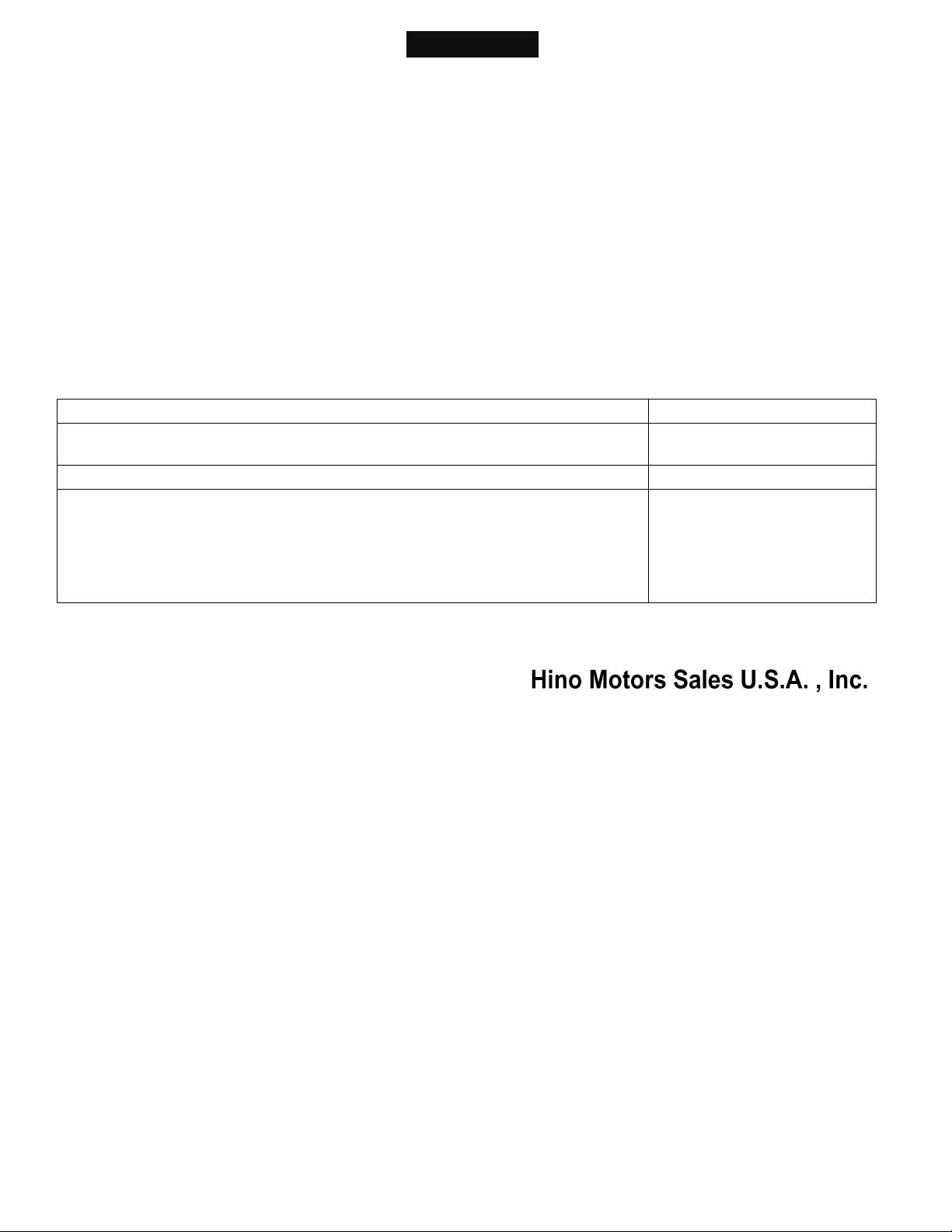
TROUBLE SHOOTING
HYBRID CONTROL SYSTEM
TROUBLE SHOOTING STEPS FOR HYBRID SYSTEM
CONFIGURATION DIAGRAM OF HYBRID TROUBLE SHOOTING SYSTEM
EN01H03ZZZ030602002001
Page 9
HYBRID/TROUBLE SHOOTING 3–5
LIGHT ON OR LIGHT OFF
HV WARNING LIGHT
HV ECU
MALFUNCTION
INFORMATION
HV BATTERY ECU
INVERTER
CLUTCH ECU
CAN:
SIGNAL LINE:
SHTS03ZZZ0300002
LIGHT ON OR
LIGHT OFF
MIL
HV ECU
MIL ON
REQUEST
ENGINE ECU
MIL ON
REQUEST
HV BATTERY ECU
INVERTER
VEHICLE CONTROL
ECU
CAN:
SIGNAL LINE:
SHTS03ZZZ0300003
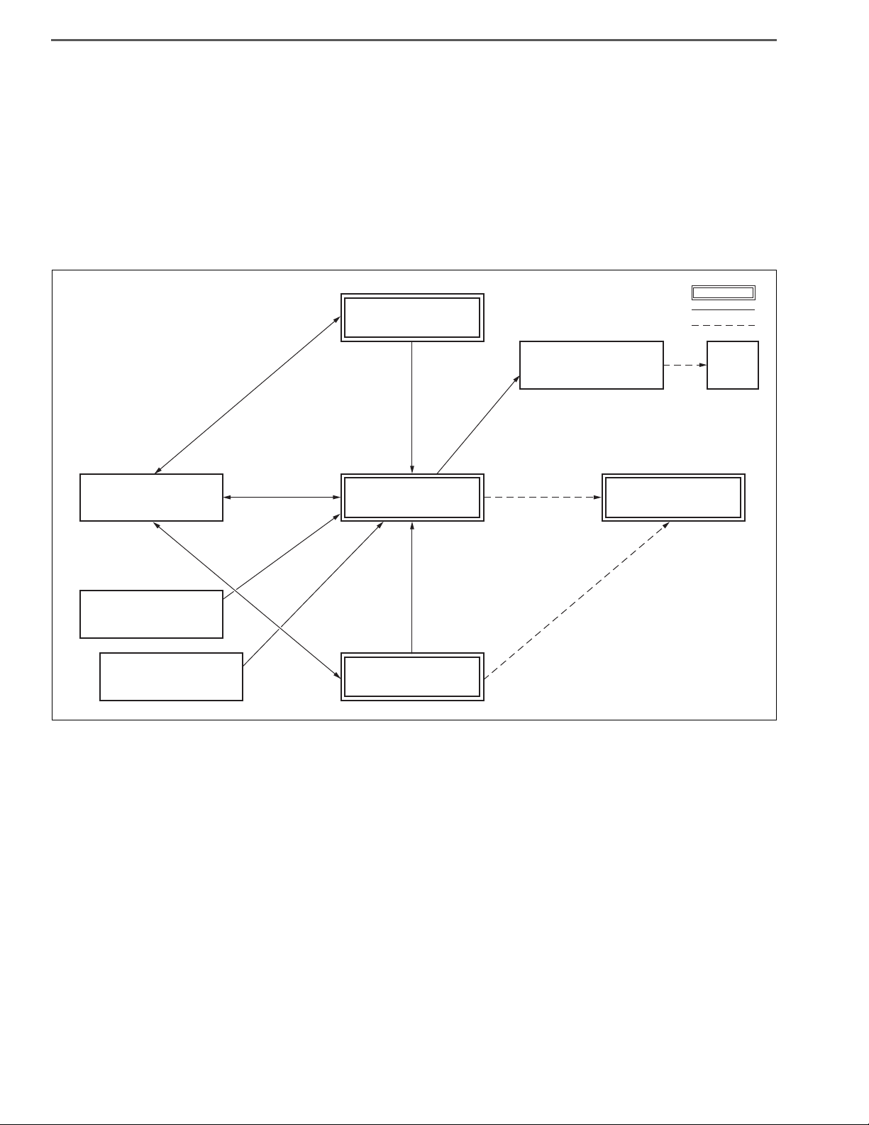
1. HV WARNING LIGHT LIGHTING PROCESS
(1) The HV ECU controls the HV warning light.
(2) The HV warning light turns on in case of malfunction of the HV ECU, the HV battery ECU, the inverter, or the
clutch ECU.
(3) The HV ECU receives information regarding malfunction of the HV battery ECU, the inverter, and the clutch ECU
via CAN.
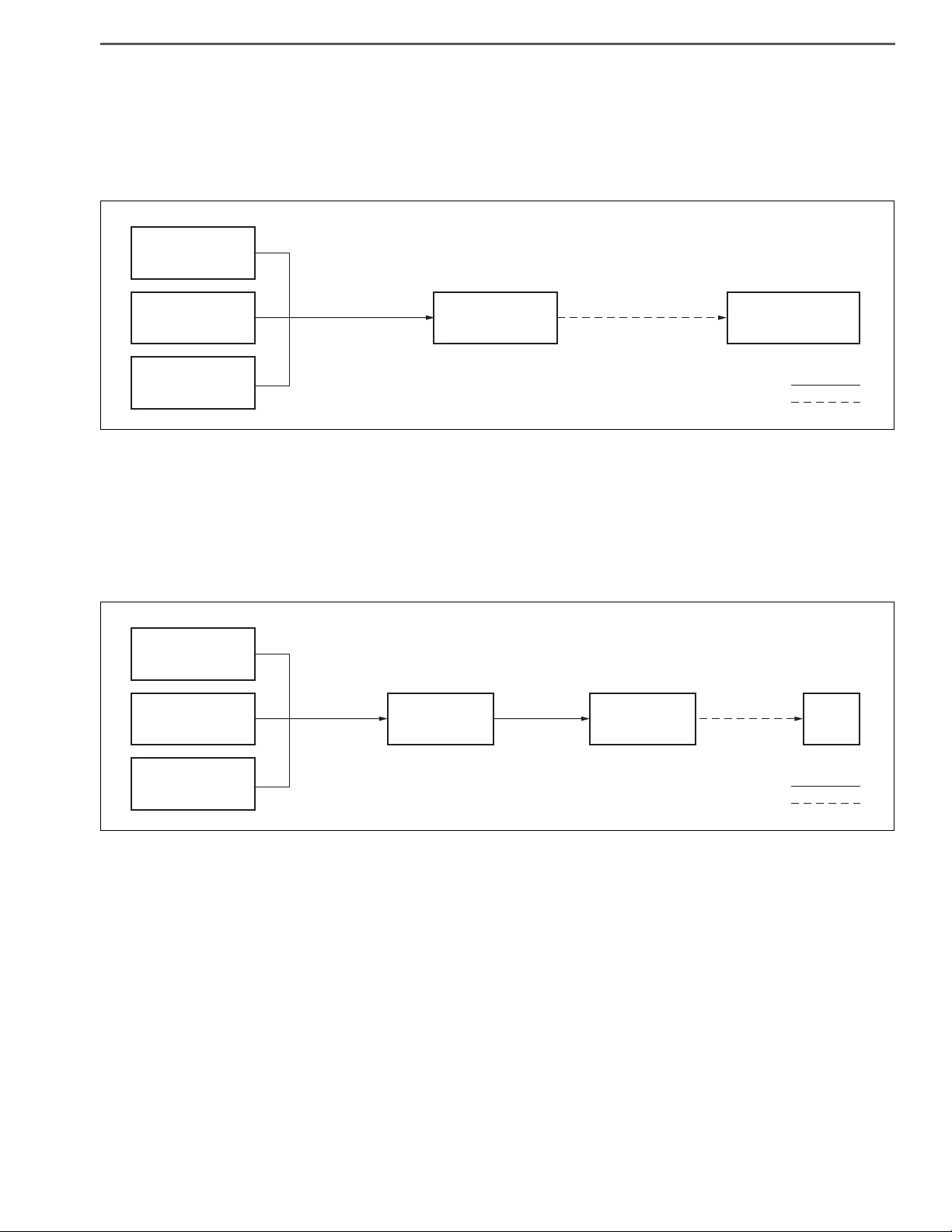
2. ABOUT MIL
(1) The engine ECU controls whether to turn on or turn off MIL.
(2) When a malfunction relevant to emission occurs in the HV system or vehicle control ECU, the MIL light ON
request is sent from the HV ECU to the engine ECU using CAN.
(3) HV battery ECU, inverter and vehicle control ECU send the MIL light ON request to the engine ECU using CAN
via HV ECU.
Page 10
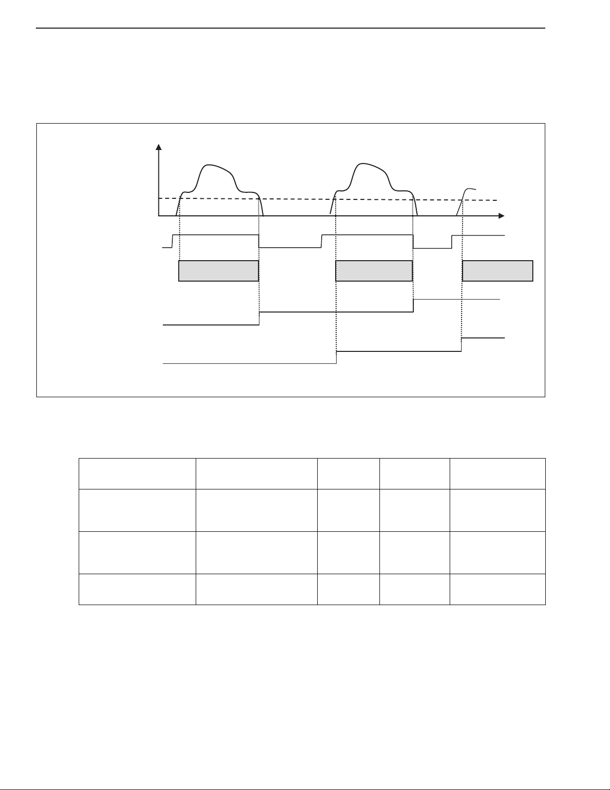
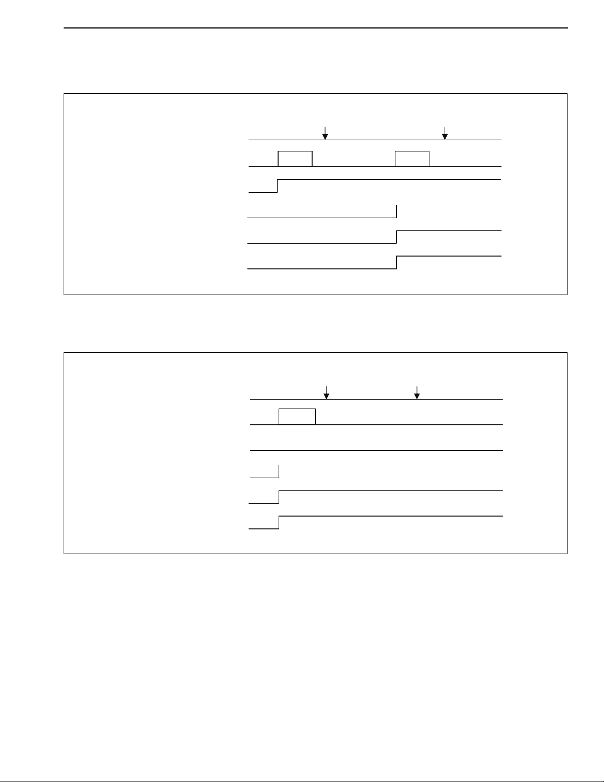
3. DEFINITION OF MALFUNCTION
DCY#3
CONFIRMATION TIME
t
COMPLETION
OF DCY#2
COMPLETION
OF DCY#2
COMPLETION
OF DCY#1
COMPLETION OF
DCY#1
DCY#1
CONFIRMATION TIME
DCY#2
CONFIRMATION TIME
ON
LOCK
[r/min]
IDLING SPEED-150 [r/min]
COMPLETION OF
HV BATTERY ECU DCY
COMPLETION OF
INVERTER DCY
STARTER KEY
DCY
COMPLETION OF
HV ECU DCY
ENGINE
SPEED
0
0
0
SHTS03ZZZ0300004
(1) Driving cycle
The driving cycle (hereinafter referred to as "DCY") is confirmed when the engine revolution becomes equal to or
more than the value calculated using the following formula [idling speed minus 150 r/min] after the starter key is
turned to the "ON" position. DCY is completed when the starter key is turned to the "LOCK" position.
HYBRID/TROUBLE SHOOTING3–6
* Completion of DCY is the timing to delete the Permanent diagnosis code and Pending diagnosis code.
(2) Definition of diagnosis code
The following table shows malfunctions that are displayed on the service tool.
Pending diagnosis code
Confirmed diagnosis
Permanent diagnosis
*1 This light lights for malfunctions relevant to emission.
*2 If a malfunction is recovered, control is switched from failsafe control to normal control; however the
Confirmed diagnosis code is not deleted.
Code name
code
code
Definition of diagnosis
code
HV warning
light
MIL Effect on vehicle
Diagnosis code that is
being detected (malfunc-
Light OFF Light OFF Normal control
tion is not confirmed).
Diagnosis code in which
the malfunction is con-
Light ON Light ON *1 Failsafe control *2
firmed
Stored diagnosis code Light OFF Light OFF Normal control
Page 11
HYBRID/TROUBLE SHOOTING 3–7
COMPLETION OF
DCY#1
COMPLETION OF
DCY#2
DETECTION OF
MALFUNCTION
CONFIRMATION
DETECTION OF
MALFUNCTION
CONFIRMATION
LIGHT ON
LIGHT ON
DCY
VEHICLE CONDITION
PENDING MALFUNCTION
CONFIRMED MALFUNCTION
HV WARNING LIGHT
MIL
SHTS03ZZZ0300005
CONFIRMATION
LIGHT ON
LIGHT ON
COMPLETION OF
DCY#1
COMPLETION OF
DCY#2
DETECTION OF
MALFUNCTION
DCY
VEHICLE CONDITION
PENDING MALFUNCTION *1
CONFIRMED MALFUNCTION
HV WARNING LIGHT
MIL
SHTS03ZZZ0300006
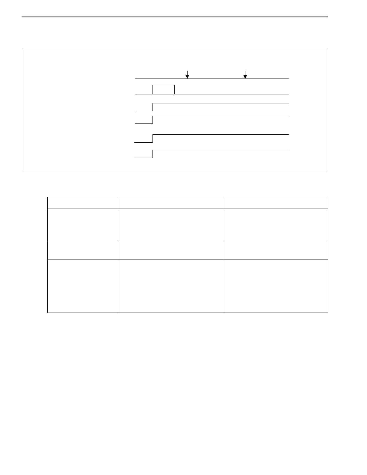
(3) Pending diagnosis code
Represents the diagnosis code in which the malfunction is confirmed by detecting the malfunction in 2DCY or
more. The following table shows examples in which the malfunction is confirmed in 2DCY.
(4) Confirmed diagnosis code
Represents the diagnosis code in which the malfunction is confirmed by detecting the malfunction in 1DCY.
*1 For the malfunction in which the Confirmed malfunction is confirmed in DCY, the Pending malfunction
is not confirmed.
Page 12
HYBRID/TROUBLE SHOOTING3–8
CONFIRMATION
CONFIRMATION
LIGHT ON
LIGHT ON
COMPLETION OF
DCY#1
COMPLETION OF
DCY#2
DETECTION OF
MALFUNCTION
DCY
VEHICLE CONDITION
CONFIRMED MALFUNCTION
PERMANENT MALFUNCTION
HV WARNING LIGHT
MIL
SHTS03ZZZ0300007
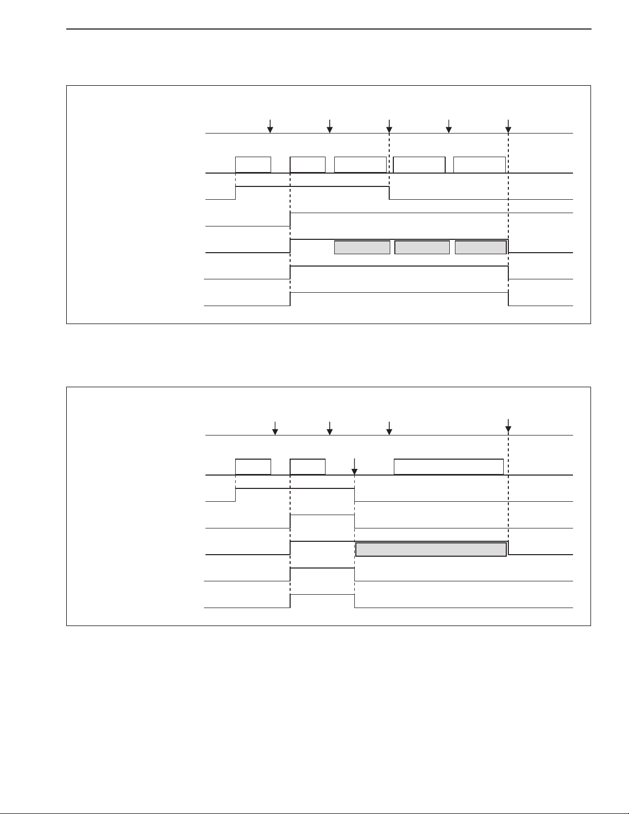
(5) Permanent diagnosis code
Permanent malfunction is confirmed by confirming the Confirmed malfunction.
(6) Deletion of diagnosis code
Code name Deletion from vehicle condition Deletion using the service tool
This code is deleted when condition
Pending diagnosis code
to be judged normal is satisfied and
malfunction detection condition is
Instant deletion
not satisfied in 1DCY
Confirmed diagnosis
code
None Instant deletion
This code is deleted after performing
the predetermined operation when
Permanent diagnosis
code
This code is deleted when condition
to be judged normal is satisfied in
3DCY. *1
condition to be judged normal is satisfied and malfunction detection con-
dition is not satisfied in 1DCY after
deleting the diagnosis code using
the service tool. *1
*1 Refer to the following figure and 4. Procedure for deleting the Permanent malfunction for details.
Page 13
HYBRID/TROUBLE SHOOTING 3–9
CONFIRMATION
DELETION
DELETION
LIGHT OFF
LIGHT OFF
LIGHT ON
LIGHT ON
CONFIRMATION
CONFIRMATION
COMPLETION OF
DCY#1
COMPLETION OF
DCY#2
COMPLETION OF
DCY#3
COMPLETION OF
DCY#4
COMPLETION OF
DCY#5
DETECTION OF
MALFUNCTION
DETECTION OF
MALFUNCTION
DCY
VEHICLE CONDITION
PENDING MALFUNCTION
CONFIRMED MALFUNCTION
PERMANENT MALFUNCTION
HV WARNING LIGHT
MIL
NORMAL JUDGMENT #1 NORMAL JUDGMENT #2 NORMAL JUDGMENT #3
NORMAL JUDGMENT
DCY#1
NORMAL JUDGMENT
DCY#2
NORMAL JUDGMENT
DCY#3
SHTS03ZZZ0300008
CONFIRMATION
DELETION
DELETION
DELETION
DELETION OF THE MALFUNCTION
CODE USING THE SERVICE TOOL
LIGHT OFF
LIGHT OFF
LIGHT ON
LIGHT ON
CONFIRMATION
CONFIRMATION
COMPLETION OF
DCY#1
COMPLETION OF
DCY#2
COMPLETION OF
DCY#3
COMPLETION OF
DCY#4
DETECTION OF
MALFUNCTION
DETECTION OF
MALFUNCTION
DCY
VEHICLE CONDITION
PENDING MALFUNCTION
CONFIRMED MALFUNCTION
PERMANENT MALFUNCTION
HV WARNING LIGHT
MIL
NORMAL JUDGMENT #1
*1
SHTS03ZZZ0300009
•
The following figure shows deletion of the Pending diagnosis code and deletion of the Permanent diagnosis
code in 3DCY.
• The following figure shows clearing of Pending malfunction code, Confirmed malfunction code, and Perma-
nent malfunction code by using the service tool.
*1 Refer to 4. Procedure for deleting the Permanent malfunction (1).
Page 14

HYBRID/TROUBLE SHOOTING3–10
! CAUTION
! CAUTION
4. PROCEDURE FOR DELETING THE PERMANENT MALFUNCTION
There are two procedures for deleting the Permanent diagnosis code.
Confirmed diagnosis code Permanent diagnosis code Deletion procedure
None Present Deletion using the procedure (1)
Present Present Deletion using the procedure (1) or (2)
Present None —
(1) Procedure for deleting the Permanent diagnosis code after deleting the diagnosis code using the service tool
a. Turn the starter key "ON".
b. Delete the diagnosis codes using the service tool.
- Delete diagnosis codes from the following systems.
• ECU of the HV system in which the Permanent diagnosis code is occurring.
(Deletion of engine ECU must be performed after performing deletion in the order of HV battery ECU
Inverter HV ECU.)
• Engine ECU
c. Set the starter key to the "LOCK" position and wait for 30 seconds or more.
d. Turn the starter key "ON".
e. Start the engine.
f. Idle the engine for 6 minutes or more.
g. Keep the engine revolution at 1,150 r/min or more for 6 minutes or longer.
h. Set the starter key to the "LOCK" position and wait for 30 seconds or more.
i. Turn the starter key "ON".
j. Start the engine.
k. Wait for 30 seconds or more.
l. Set the starter key to the "LOCK" position.
• Trouble shooting the malfunction is conducted before following the above procedure, therefore the malfunction
does not occur or the malfunction does not occur while following the above procedure.
• The HV warning light must turn off when the diagnosis code is deleted at (b).
When the HV warning light turns off, it is possible to check that there is no malfunction in the HV system.
• Condition to be judged normal for the malfunction occurred in the above steps (d) to (g) must be satisfied.
Condition to be judged normal varies depending on malfunction.
(2) Procedure for deleting the Permanent diagnosis code in 3DCY
a. Turn the starter key "ON".
b. Start the engine.
c. Idle the engine for 2 minutes or more.
d. Set the starter key to the "LOCK" position.
e. Wait for 30 seconds or more.
f. Repeat the steps from (a) to (e) for 3 times in total (3DCY).
g. Turn the starter key "ON".
h. Start the engine.
i. Wait for 30 seconds or more.
j. Set the starter key to the "LOCK" position.
• The above procedure is satisfied when making normal driving operation; therefore the Permanent diagnosis
code may be deleted when making similar driving operation if the malfunction is recovered.
• Trouble shooting the malfunction is conducted before following the above procedure, therefore the malfunction
does not occur or the malfunction does not occur while following the above procedure.
• Condition to be judged normal for the malfunction occurred in the above steps (a) to (d) must be satisfied. Con-
dition to be judged normal varies depending on malfunction.
Page 15

HYBRID/TROUBLE SHOOTING 3–11
! CAUTION
5. TROUBLE SHOOTING PROCEDURE
(1) Trouble shooting procedure (when using genuine Hino service tool)
a. Check the DTC of the HV ECU using the service tool (trouble shooting tool).
b. Record the DTC and TC No. (detailed DTC) of freeze frame data.
c. Perform trouble shooting for the relevant DTC. For an inverter/HV battery line malfunction, read the DTC of
each ECU for trouble shooting according to the HV ECU diagnostic chart.
d. After trouble shooting, delete the DTC of each ECU using the service tool and conduct a trial running to check
that the malfunction does not recur.
• When inspecting the high voltage line, wear insulating gloves because of a risk of electrical shock. Before per-
forming inspection, be sure to remove the service plug after the starter key is turned to the "LOCK" position.
When inspecting the HV battery, wear safety glasses.
Do not touch the terminals of the high voltage line for 7 minutes after removing the service plug.
• One diagnosis code (DTC) may contain more than 1 malfunction. Read TC No. (detailed DTC) of freeze frame
data with the trouble shooting tool and perform trouble shooting according to the relevant trouble shooting
chart.
• When inspecting the harness, first check the connector for fitting looseness, and the fitting surface for entry of
foreign matters.
• There may be irregular contact or temporary noise due to partial fitting of the connector if parts are returned to
normal without repairing or replacing parts using the diagnostic chart.
• The service tool or trouble shooting tool described in the trouble shooting chart indicates the genuine Hino ser-
vice tool.
• If the starter key is turned "ON" in the state that connectors, etc. are disconnected while performing the trouble
shooting chart, the malfunction may be recorded due to disconnection of a connector. In such case, be sure to
delete the diagnosis code using the trouble shooting tool.
HINT
If there is no malfunction and the engine does not stop with the idling stop function, the following cases are conceivable.
• A vehicle is not running at vehicle speed of 5 km/h or more from the last idling stop.
• The change lever is located at a position other than "D" and "4".
• When the turn signal light and the hazard light are ON. (Even if the turn signal light switch signal and the hazard
light switch signal transmitted to the HV ECU are Low, the engine does not stop automatically by use of the
idling stop function.)
• When a vehicle stopped on a sloped road.
• While PTO is operating.
• While DPR is operating.
• Capacity of the HV battery is low.
• Engine coolant temperature is low.
• The engine is still running. (The engine is running at approximately 1 km/h or more.)
• When the status of the idling stop cancel switch is "ON".
• Brake vacuum pressure is low. (Even if the low brake vacuum pressure switch signal transmitted to the HV ECU
becomes Low, the engine does not stop automatically by use of the idling stop function.)
Page 16

HYBRID/TROUBLE SHOOTING3–12
!WARNING
!CAUTION
1
2
3
SHTS03ZZZ0300010
SAFETY MEASURES FOR HIGH-VOLTAGE
WORK
EN01H03ZZZ030602002002
1. CAUTIONS ON INSPECTION OF HYBRID CONTROL SYSTEM
(1) To inspect the high-voltage system or disconnect the low-
voltage connector in the PCU box, be sure to take actions to
prevent electric shocks, i.e. wearing insulated gloves and disconnection of service plug. Removed service plug should be
put in a pocket so as to prevent other engineers from using it
by mistake during work.
Note that the SMR is turned "ON" and high-voltage circuit is activated when the starter key is turned to "ON."
Since any failure may occur when the starter key is turned to "ON"
with the service plug removed, never turn the starter key to "ON"
unless otherwise instructed in this document.
(2) All wire harness connectors for the high-voltage circuit are
orange colored. Further, "HIGH VOLTAGE" caution label is
attached to high-voltage components such as the hybrid battery. Do not touch these wiring and components unnecessarily.
(3) Turn the starter key "LOCK" and remove the service plug.
Then wait for at least 7 minutes before starting the work.
NOTICE
In the 7 minutes the high-voltage capacitor in the inverter discharges.
Page 17

HYBRID/TROUBLE SHOOTING 3–13
! CAUTION
INCORRECT
SHTS03ZZZ0300011
(4) Check the insulated gloves for damage such as cracks and
break before use. Also, do not use wet insulated gloves.
(5) Do not carry on any metal product such as a pen and scale
which may fall to cause short circuit while working.
(6) Be sure to wear insulated gloves when it is necessary to
touch any high-voltage terminal without insulating coating.
(7) After disconnecting high-voltage connectors and terminals,
insulate them with insulator tape without delay.
(8) After working on high-voltage components, check for any
component or tool left, tightening condition of high-voltage
terminals and connector conditions again before connecting
the service plug.
(9) Do not reserve the hybrid battery.
(10) Do not disassemble the hybrid battery.
High voltage is applied to the hybrid battery even when the service plug is disconnected. Further, high-alkaline electrolyte is
used.
(11) Make sure to use the insulated tools.
Recommended tools: FACON's Facom-quality insulated tools
(12) Turn the starter key to "LOCK" for resistance inspection.
(13) Turn the starter key to "LOCK" before removing/installing
connectors.
(14) Alert other workers with indication such as "High-voltage
work. Don't touch" on the vehicle during works on high-volt-
age components.
(The next page is an example of the indication. You may copy
and use it.)
Page 18

HYBRID/TROUBLE SHOOTING3–14
SHTS03ZZZ0300012
Page 19

HYBRID/TROUBLE SHOOTING 3–15
WHITE
WHITE
ORANGE
BLACK
BLACK
BLACK
DARK GRAY
WHITE
WHITE
WHITE
132
23
456789
11112
2316221521
142013
2417251826
19
10
1
9 10111213141516
2345678
1
12 13 14 15 16 17 18 19 20 21 22
10 1123456789
1
5
23
6748
11 12 13 14 15 16 17 18 19
23456789
20
2423 25 26 27 28 29
21 22
30
110
1234
1
2
3
4
56789
10 11
30 31
12
13
14
15
1617 1819 20
2122 2324 25 26272829
3233 3435 36 373839 40
78910
11 123413 14 15 16
17 18 19 20 21 22 23 24
12 56
1819
20 21 22 23 24 25 26
7 8 9 1011121314151617
123456
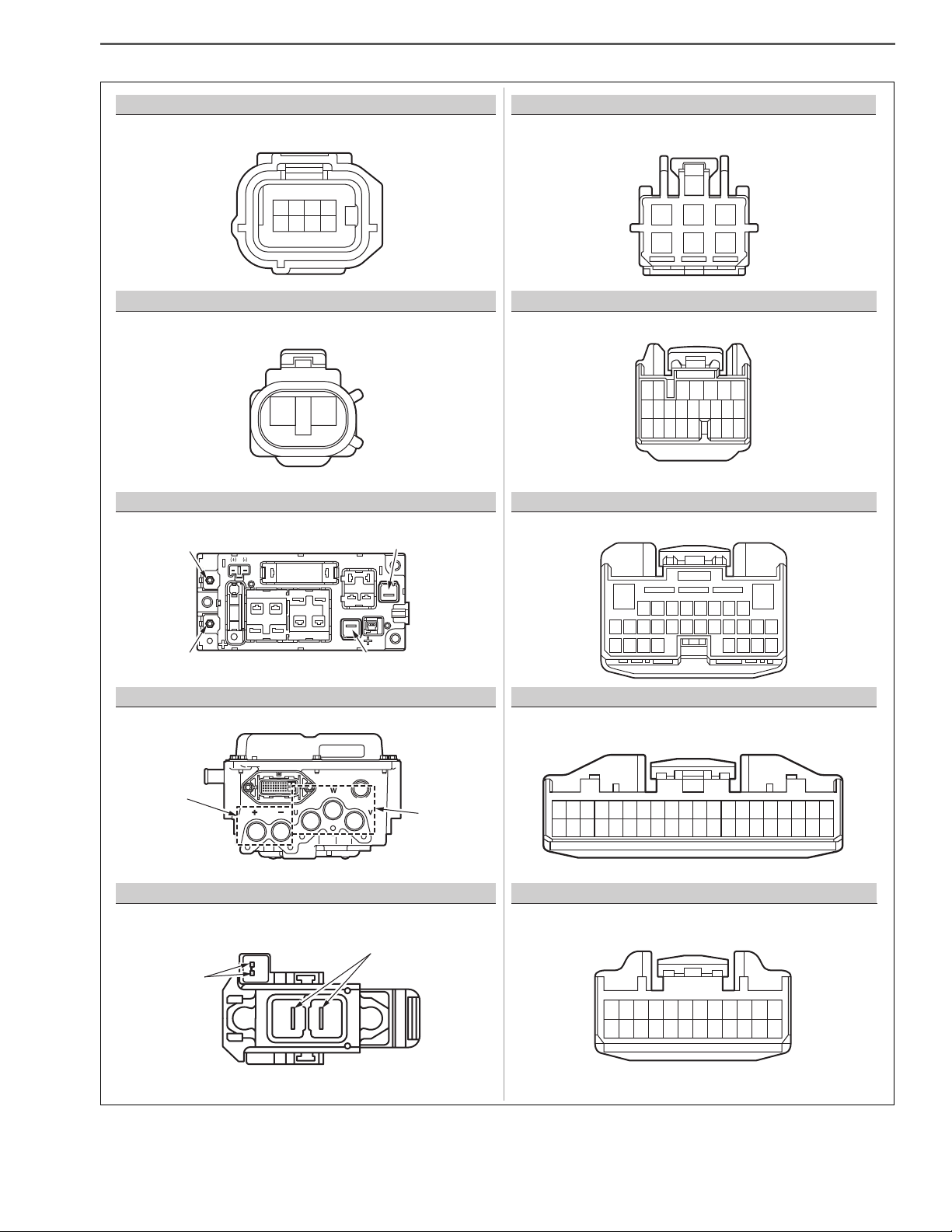
BATTERY ECU (CAN)A
B
F
G
J/C DIAG CAN
INVERTER COOLING WATER PUMP
BATTERY ECU (TEMPERATURE MONITORING)
C
H
HV ECU1
BATTERY ECU (VOLTAGE MONITORING)
D
I
HV ECU2
INVERTER
E
J
HV ECU3
INVERTER COOLING RADIATOR FAN
SHTS03ZZZ0300013
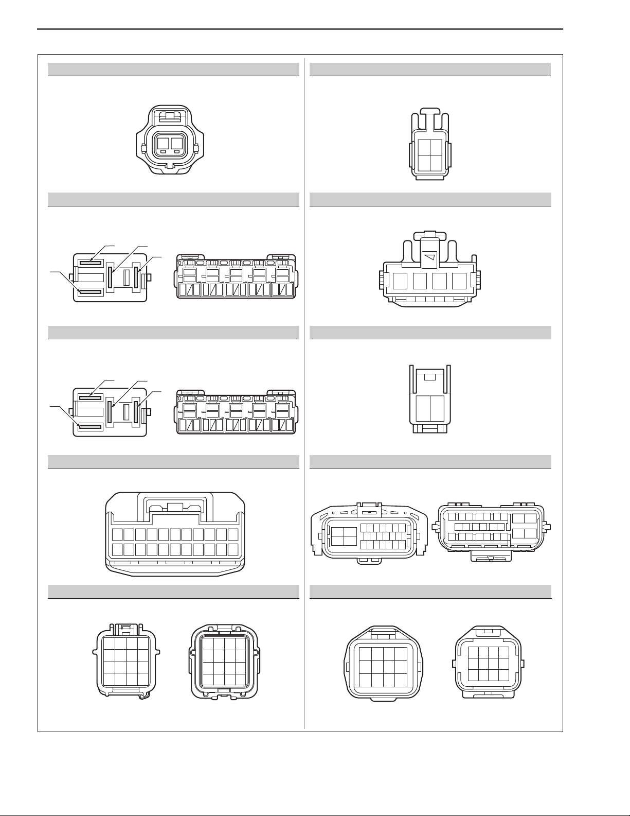
LIST OF CONNECTOR SYMBOLS
EN01H03ZZZ030602002003
Page 20
HYBRID/TROUBLE SHOOTING3–16
123456
16 17
78910
12 13 14 15 18 19 20 211122
12 11 10
1
65
78
9
234
10 11 12
234
56
78
9
1
21
17 16
34567
8
101112131415
181920212223
9
24
3456789
1011 1213 1415
1819 202122 2324
2
17
1
16
21
1234
12
34
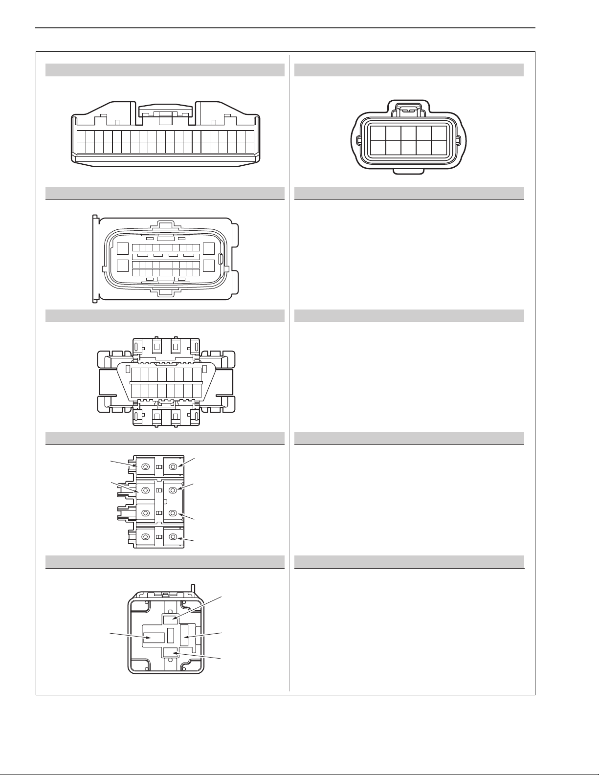
GRAY BLACK
WHITE
(RELAY BLOCK SIDE)
BLACK
BLACK BLACK
BLACK
WHITE
WHITE
BLACK BLACK
1234
5678
9 101112
13 14 15 16
4321
8765
12 11 10 9
16 15 14 13
(RELAY BLOCK SIDE)
(COMPONENT SIDE)
(COMPONENT SIDE)
3
5
L
N
2
1
3
5
2
1
12
INVERTER START RELAY
L
N
HV BATTERY START RELAY
O J/C CTRL CAN
P PCU HARNESS 16-PIN
R
HV BATTERY COOLING FAN
S
SMR DRIVE
SERVICE PLUG SWITCH
T
X PCU HARNESS 24-PIN
K
COOLANT TEMPERATURE SENSOR
PCU HARNESS 12-PINY
SHTS03ZZZ0300014
Page 21
HYBRID/TROUBLE SHOOTING 3–17
BLACK WHITE
BLACK WHITE
WHITE
WHITE
WHITE
12
2
13
1
2
12 3 4 5 6
816
17
7
9101112131415
21
201918 22 23 24
123
456
1526374
8
123456789101112
242322212019181716151413
E’: BATT IN(-)C’: BATT OUT(-)
F’: BATT IN(+)D’: BATT OUT(+)
I’
J’
H’
G’
10
12 13 14 15 16 17 1819 20
23456789
21
241123 2526 27 28 292230
1
1212223234245256267278289
29 301031113212331334143515361637173818391940
20
METER 1
d-1
A’
RESOLVER
B’
ROTATION MACHINE TEMPERATURE SENSOR
C’ D’ E’ F’
G’ H’
HIGH VOLTAGE J/B (IN BATTERY PACK)
INVERTER HIGH VOLTAGE
I’ J’ SERVICE PLUG
a
STARTER SWITCH
b
AT ECU
c
VEHICLE CONTROL ECU
d-2 METER 2
SHTS03ZZZ0300015
Page 22
HYBRID/TROUBLE SHOOTING3–18
BLACK
BLACK BLACK
BLACK
1212223234245256267278289
29 301031113212331334143515361637173818391940
20
5
1
3
2
4
6789
1314
24151617 1819 20 2122 23
252627 28 2930 3132 3334
161514131211109
87654321
h: BATT(-)
m: BATT(+)
p: INV(+)
3
1
2
5
q: INV(-)
k: DDC(-)
I: DDC(+)
1011
12
e
f
ABS ECU
CLUTCH ECU
k, l, m, n, p, q
HIGH VOLTAGE J/B (IN ECU-BOX)
r
IG1-1 RELAY
t
NEUTRAL SWITCH
h
DLC3
1
10
5432
8967
SHTS03ZZZ0300016
Page 23
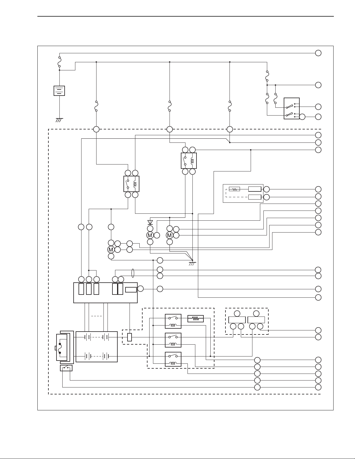
HYBRID/TROUBLE SHOOTING 3–19
F_HV_10A
INVERTER
START RELAY
W/TEMP_SSR
MF_PWR_1_50A
F_AM2_10A
F_AM1_10A
CANL
SMR1
HIGH VOLTAGE J/B
(IN BATTERY PACK)
HIGH VOLTAGE J/B
(IN ECU BOX)
HOUSING GND
SMR2
SMR3
IG2
IGCT
AM
CANH
BATTERY ECU
SERVICE PLUG
288V
HV BATTERY
CURRENT
SENSOR
GND
L1L
L
x
PCI_B_2 20A
PCI_B_20A
x
L
3
np
J/B (+)
l
25
WATER PUMP
RADIATOR FAN
HV BATTERY
START RELAY
F
F
E
F
F
E
E
4
1
3
3
2
R
RP
P
R
3
A1A2A
13
A18A
19
A
12
9
P13P
14
4
1
2
111
RP
212
P
15
P
6
P
7
P
2
3
4
5
1
P
16
N1N
x
NN
3
123
25
1
2
3
4
5
6
7
8
9
12
11
10
14
13
15
16
18
19
20
21
22
23
24
25
mq
J/B (-)
k
P
P
P
P
HV BATTERY
COOLING FAN
KEY CYLINDER
ON
ST
THW
E2
K
K
a
6
2
1
17
SMR: System Main Relay
SHTS03ZZZ0300017
HV SYSTEM WIRING DIAGRAM
EN01H03ZZZ030602002004
Page 24
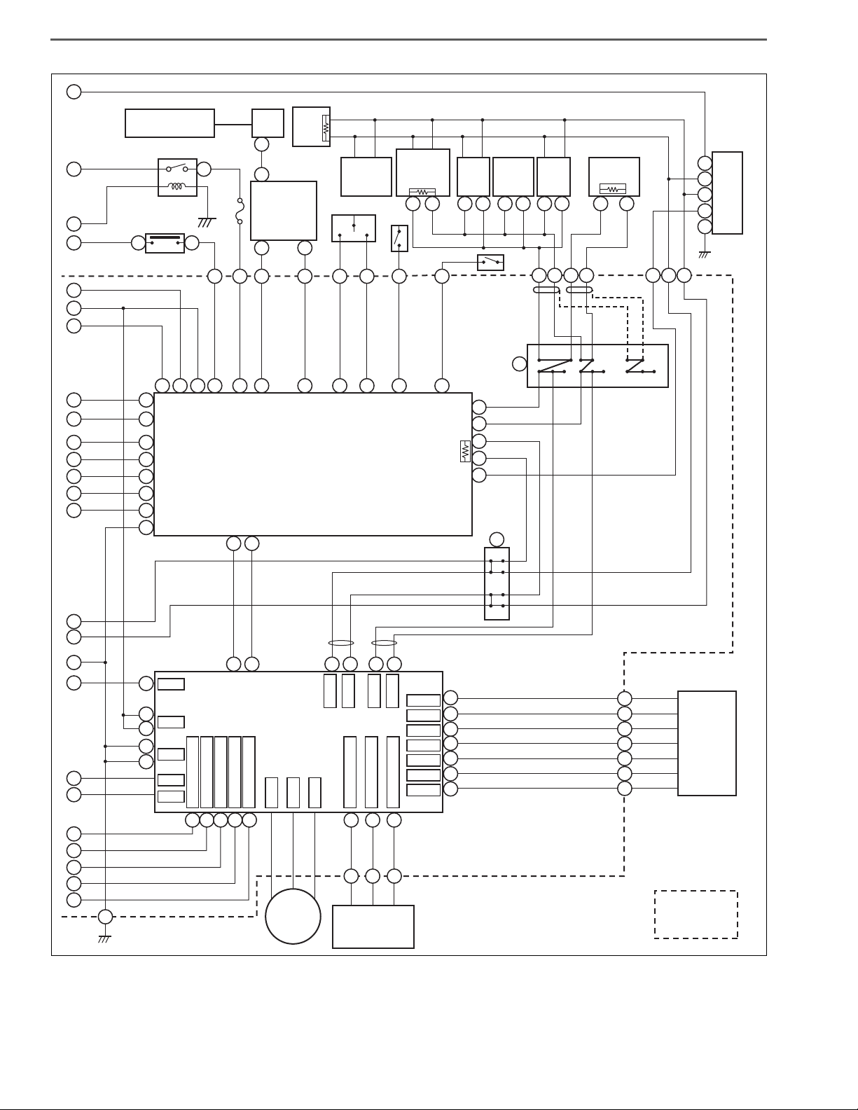
HYBRID/TROUBLE SHOOTING3–20
DCU
F_ECU_IG_NO.1_10A
VEHICLE SPEED
PULSE
HV WARNING
LIGHT
IG1-1
76
61
15 2520 19
X
J
o
J
X
VEHICLE
CONTROL
ECU
VCM WARN SW
or
A/C WARN SW
HYD WARN SW
HAZ SW
TURN SW
WHEEL SPEED
SENSOR
ABS
ECU
METER
CANL1
CANH1
32
D
9
3
D
I
8
7
D
I
21 22
D
CANL2
CN4-26 SLD4
CN4-35 THA1
CN4-34 P5A1
R1
CANH2
33
DD
23
D
30
D
31
D
10
D
11
D
25
D
38D39D40D16D5
D
34D35D26
D
24
D
12
D
14
D
13
D
15
D
27
D
3Y8
Y
4
Y
ROTATION
MACHINE
THERMISTER
ROTATION
MACHINE
16
X
W1
V1
U1
CN4-40 CON3
CN4-39 CON2
CN3-38 CON1
CN4-16 ILK1
CN4-5 ILKO
INVERTER
PCU
INTERNAL
CIRCUIT
HV ECU
CAN J/C
(CONTROL)
CAN J/C (DIAG)
cc
ABS
ECU
20
H
29
Y
1
R2
Y
2
S1
Y
5
S2
Y
6
RESOLVER
S3
Y
10
S4
F+
F-
GND
+B
ON
Y
11
SLD3
Y
9
19
J
21
J
22
J
G
h
h
h
h
h
DLC3
15
56
34
78
12
ff
X
xxx
X
CLUTCH
ECU
13
23
I
1
127
8
12 13
16
1411109543
24 21 22
20 8 9
14
16
6
14
13
4
ee
21 20
AT
ECU
ENGINE
ECU
bb
METER
d2 d2
I2J1H
XX
4J3
X
J
24
X
d1
1
2
3
4
5
6
7
8
9
14
15
16
18
17
19
20
21
22
23
24
25
d1
tt
r
22
NSSW
22
f
23
18
19
5
7
12
d1
H
11
X
4
H
20
X
19
H
19
X
10
H
9
X
11
RL
H
18
5
H
30
12
I
17
I
18
11
10
H
26
13
H
24
H
25
J
5
15
SHTS03ZZZ0300018
NOTICE
For connector symbols, refer to "List of connector symbols."
Reference: HYBRID, TROUBLE SHOOTING, HYBRID CONTROL SYSTEM, LIST OF CONNECTOR SYMBOLS (Page
3-15)
Page 25

HYBRID/TROUBLE SHOOTING 3–21
Gradual braking
Sudden braking
Operation by left foot
Engine
HV
Details of the
vehicle
Result of interviewConfirmation result of vehicle
Vehicle type
Date of occurrence
Warehousing date
Travel distance Km
Registration date
Sex
Male
Urban area
Mountain
( )
Suburb
Others
Female
Age group
Age
Occupation
Previous vehicle
Frequency of use
Others
Others
Main place
for use
Characteristic of the customer
(Scheduled) delivery date of the vehicle
Frame No.
Unit No. or the like
Option
Details of interview (Please describe the situation prior to the occurrence and before and
after the occurrence in a time-series manner as much as possible.)
Cold area Others ()
Frequency / date /
week month
Running condition Road surface state
When starting
During acceleration
During steady running
During deceleration
During braking
During stoppage
During parking
During turning
During ABS operation
Others
( )
Vehicle speed [km/h]
Shift position (display) Lighting of warning light
Brake operation
Frequency of occurrence
A/C status
1234
5
at operation
6R
Engine status
Flat (horizonal) road
Upward ° Downward
Inclination ° .%
Distance km
Dry paved road
Wet paved road
Rough paved road
Unpaved road
Snow road, compressed
snow road, frozen road
Uneven road, curbstone
Others
( )
At start
Immediately after the
start
After minutes after
the start
After minutes after
the start of running
At the stoppage of the
system
During engine stoppage
During engine start
During engine rotation
Yes No
Charge
Engine
Others
(ޓޓޓޓ)
Yes No
Engine
Brake
ABS
Brake
HV
Others
( )
Always
Sometimes
Only one time
Vehicle state
Confirmation result of warning lamp Confirmation result of diagnosis code
Charge
Weather:
Air temperature: °C
Amount of remaining fuel
(fuel gauge)
Remaining amount
A/C
OFF
FULL
Unknown
SHTS03ZZZ0300019
HEARING SHEET
1. HEARING OF REQUESTS FROM CUSTOMER
(1) As the steps of trouble shooting are advanced, hear requests from customer without fault by referring this hear-
ing sheet.
EN01H03ZZZ030602002005
Page 26

HYBRID/TROUBLE SHOOTING3–22
HYBRID ECU
DIAGNOSIS CODE TABLE
Symbol Lighting pattern
☆ Light is turned on when any fault occurs, and off when the fault is resolved
DTC
No.
P0500
P0501
P0562
Diagnosis code
name
Abnormality in
vehicle speed
sensor
Abnormality in
characteristics
of vehicle
speed sensor
Abnormality in
power supply
voltage
TC
Description of
No.
51
5B
71
malfunction
No vehicle
speed signal
input
Abnormality in
characteristics
of the vehicle
speed sensor
Control power
supply voltage
reduction
Vehicle behavior for occur-
rence of malfunction
Idling stop is not working.
Lowering the speed during
deceleration may decrease
to deactivate the regeneration function.
Idling stop is not working. 1 ☆☆
HV system stop
Since the hybrid system
stops, the following symptom occur.
- The engine may not start
running. However, the
engine starts up by the
starter for starter-equipped
vehicles.
- Idling stop is not working.
- Lowering the speed during
deceleration may decrease
to deactivate the regeneration function.
EN01H03ZZZ030602003001
Number
of mal-
function
confir-
mation
DCY
1 ☆☆
1 ☆
HV
Warning
Light
MIL
P060B
P0617
P062F
P0810
Abnormality in
A/D converter
Malfunction of
starter switch
Abnormality in
EEPROM
Abnormality in
clutch system
(idling stop
inhibited)
Abnormality in
B2
the A/D converter
Sticking the
59
starter signal
circuit to High
EEPROM
B3
abnormality
Abnormality in
the clutch ECU
9C
(idling stop is
prohibited.)
Idling stop is not working.
Lowering the speed during
deceleration may decrease
to deactivate the regeneration function.
Idling stop is not working. 1 ☆☆
Recording a diagnosis code
may not be available.
Idling stop may not work. 1 ☆
1 ☆☆
1 ☆☆
Page 27

DTC
No.
Diagnosis code
name
TC
Description of
No.
HYBRID/TROUBLE SHOOTING 3–23
Number
malfunction
Vehicle behavior for occur-
rence of malfunction
of mal-
function
confirmation
DCY
HV
Warning
Light
MIL
P0810
P0A01
P0A02
P0A03
Abnormality in
clutch system
(idling stop
available)
Abnormality in
characteristics
of inverter coolant temperature sensor
Coolant temperature sensor Low
abnormality
Coolant temperature sensor High
abnormality
Abnormality in
the clutch ECU
9D
(idling stop is
available.)
Abnormality in
characteristics
7B
of the inverter
coolant temperature sensor
GND short circuit of the
inverter cool-
78
ant temperature sensor
circuit
Inverter coolant temperature sensor
circuit discon-
79
nected or
power supply
(positive side)
shorted
Idling stop may not work. 1 ☆
Behavior of vehicle does not
vary.
Behavior of vehicle does not
vary.
Behavior of vehicle does not
vary.
2 ☆☆
1 ☆☆
1 ☆☆
P0A06
P0A07
P0A0F
P0A1D
HV water pump
drive signal
Low abnormality
HV water pump
drive signal
High abnormality
Engine system
abnormality
Abnormality in
HV ECU function
Disconnection
or GND short
circuit of the HV
7F
water pump
drive signal circuit
HV water pump
drive signal cir-
7E
cuit power supply (positive
side) shorted
31 Engine misfire
Sticking of the
12
control CAN
register
Behavior of vehicle does not
vary.
Behavior of vehicle does not
vary.
The engine does not start
running. However, the
engine starts up by the
starter for starter-equipped
vehicles.
Idling stop is not working.
Idling stop is not working.
Lowering the speed during
deceleration may decrease
to deactivate the regeneration function.
CHG, AST, ECO and SOC
lights may turn off.
1 ☆☆
1 ☆☆
1
1 ☆☆
Page 28

DTC
No.
P0A1D
P0A78
Diagnosis code
name
Abnormality in
HV ECU function
Abnormality in
the inverter
TC
Description of
No.
17
21
malfunction
Sticking of the
DIAG CAN register
Serious abnormality in the
inverter
HYBRID/TROUBLE SHOOTING3–24
Number
Vehicle behavior for occur-
rence of malfunction
Idling stop is not working.
Lowering the speed during
deceleration may decrease
to deactivate the regeneration function.
CHG, AST, ECO and SOC
lights may turn off.
The engine may not start
running. However, the
engine starts up by the
starter for starter-equipped
vehicles.
Idling stop may not work.
Lowering the speed during
deceleration may decrease
to deactivate the regeneration function.
of mal-
function
confir-
mation
DCY
1 ☆☆
1 ☆
HV
Warning
Light
MIL
P0A78
P0A7E
P0A82
P0A84
Abnormality in
the inverter
Abnormality in
high temperature of HV battery
Abnormality in
function of HV
battery cooling
fan
Abnormality in
HV battery
cooling fan
drive signal
Low
Slight abnor-
22
mality in the
inverter
Abnormally
high tempera-
48
ture of the HV
battery
Abnormality in
the HV battery
67
cooling FAN
function
Disconnection
or GND short
circuit of the HV
66
battery cooling
FAN drive signal circuit
The engine may not start
running. However, the
engine starts up by the
starter for starter-equipped
vehicles.
Idling stop may not work.
Lowering the speed during
deceleration may decrease
to deactivate the regeneration function.
Idling stop is not working.
Lowering the speed during
deceleration may decrease
to deactivate the regeneration function.
Behavior of vehicle does not
vary.
Behavior of vehicle does not
vary.
1 ☆
1 ☆☆
2 ☆☆
1 ☆☆
P0A85
Abnormality in
HV battery
cooling fan
drive signal
High
HV battery
cooling fan
drive signal cir-
65
cuit power supply (positive
side) shorted
Behavior of vehicle does not
vary.
1
☆☆
Page 29

DTC
No.
P0A90
Diagnosis code
name
Abnormality in
motor function
TC
Description of
No.
2A
malfunction
Abnormality in
the motor function
HYBRID/TROUBLE SHOOTING 3–25
Number
Vehicle behavior for occur-
rence of malfunction
The engine may not start
running. However, the
engine starts up by the
starter for starter-equipped
vehicles.
Idling stop is not working.
Lowering the speed during
deceleration may decrease
to deactivate the regeneration function.
of mal-
function
confirmation
DCY
1 ☆☆
HV
Warning
Light
MIL
P0A92
P0A93
P0AFD
P0BCA
P0C73
P3000
Abnormality in
charging performance
Abnormality in
inverter cooling system
Abnormality in
low temperature of HV battery
Abnormality in
HV battery
cooling fan
revolving number signal High
Abnormality in
HV water pump
function
Abnormality in
status of HV
battery ECU IG
signal
Abnormality in
29
HV battery
charging power
Abnormally
high tempera-
7A
ture of the
inverter coolant
Abnormally low
6B
temperature of
the HV battery
HV battery
cooling fan
speed signal
68
circuit power
supply (positive
side) shorted
Abnormality in
80
the HV water
pump function
Abnormality in
the HV battery
42
ECU IG signal
status
Behavior of vehicle does not
vary.
Idling stop is not working.
Lowering the speed during
deceleration may decrease
to deactivate the regeneration function.
Idling stop is not working. 2 ☆☆
Behavior of vehicle does not
vary.
Behavior of vehicle does not
vary.
Idling stop is not working.
Lowering the speed during
deceleration may decrease
to deactivate the regeneration function.
2 ☆☆
1 ☆☆
1 ☆☆
2 ☆☆
1 ☆
P3001
Abnormality in
HV battery line
Abnormality in
the HV battery
41
ECU memory
system
The engine may not start
running. However, the
engine starts up by the
starter for starter-equipped
vehicles.
Idling stop is not working.
Lowering the speed during
deceleration may decrease
to deactivate the regeneration function.
1 ☆
Page 30

DTC
No.
P3001
P3001
Diagnosis code
name
Abnormality in
HV battery line
Abnormality in
HV battery line
TC
Description of
No.
43
44
malfunction
Abnormality in
the HV battery
system
Abnormality in
the HV battery
system
HYBRID/TROUBLE SHOOTING3–26
Number
Vehicle behavior for occur-
rence of malfunction
The engine may not start
running. However, the
engine starts up by the
starter for starter-equipped
vehicles.
Idling stop is not working.
Lowering the speed during
deceleration may decrease
to deactivate the regeneration function.
The engine may not start
running. However, the
engine starts up by the
starter for starter-equipped
vehicles.
Idling stop is not working.
Lowering the speed during
deceleration may decrease
to deactivate the regeneration function.
of mal-
function
confir-
mation
DCY
1 ☆
1 ☆
HV
Warning
Light
MIL
P3001
P3001
P3001
Abnormality in
HV battery line
Abnormality in
HV battery line
Abnormality in
HV battery line
Disconnection
of the HV bat-
45
tery high voltage fuse
Request for
stopping dis-
46
charge of the
HV battery
Auxiliary
charge request
47
for the HV battery
The engine may not start
running. However, the
engine starts up by the
starter for starter-equipped
vehicles.
Idling stop is not working.
Lowering the speed during
deceleration may decrease
to deactivate the regeneration function.
- The engine may not start
running. However, the
engine starts up by the
starter for starter-equipped
vehicles.
- Idling stop is not working.
- Lowering the speed during
deceleration may decrease
to deactivate the regeneration function.
The engine may not start
running. However, the
engine starts up by the
starter for starter-equipped
vehicles.
Idling stop is not working.
Lowering the speed during
deceleration may decrease
to deactivate the regeneration function.
1 ☆
1 ☆
1 ☆
Page 31

DTC
No.
P3001
P3001
Diagnosis code
name
Abnormality in
HV battery line
Abnormality in
HV battery line
TC
Description of
No.
4A
4B
malfunction
Abnormal
external overload in the HV
battery
Abnormality in
the HV battery
voltage detection circuit
HYBRID/TROUBLE SHOOTING 3–27
Number
Vehicle behavior for occur-
rence of malfunction
The engine may not start
running. However, the
engine starts up by the
starter for starter-equipped
vehicles.
Idling stop is not working.
Lowering the speed during
deceleration may decrease
to deactivate the regeneration function.
The engine may not start
running. However, the
engine starts up by the
starter for starter-equipped
vehicles.
Idling stop is not working.
Lowering the speed during
deceleration may decrease
to deactivate the regeneration function.
of mal-
function
confirmation
DCY
1 ☆
1 ☆
HV
Warning
Light
MIL
P3001
P3009
P3128
P3129
P314C
Abnormality in
HV battery line
Abnormality in
leakage
Abnormality in
HV radiator fan
revolution number Low
Abnormality in
HV radiator fan
revolution number High
Abnormality in
HV water pump
revolution number signal Low
Stoppage of the
regeneration
function
4C
according to
request for
stopping
charge
Electrical leak-
49
age
HV radiator fan
7D
revolution signal Low failure
HV radiator fan
7C
revolution signal High failure
GND short circuit of the HV
82
water pump
revolution signal circuit
The engine may not start
running. However, the
engine starts up by the
starter for starter-equipped
vehicles.
Idling stop is not working.
Lowering the speed during
deceleration may decrease
to deactivate the regeneration function.
Behavior of vehicle does not
vary.
Behavior of vehicle does not
vary.
Behavior of vehicle does not
vary.
Behavior of vehicle does not
vary.
1 ☆
1
2 ☆☆
2 ☆☆
1 ☆☆
Page 32

DTC
No.
Diagnosis code
name
TC
Description of
No.
HYBRID/TROUBLE SHOOTING3–28
malfunction
Vehicle behavior for occur-
rence of malfunction
Number
of mal-
function
confir-
mation
DCY
HV
Warning
Light
MIL
P314D
P324B
P324C
Abnormality in
HV water pump
revolution number signal High
Abnormality in
inverter start
relay Low
Abnormality in
inverter start
relay High
Disconnection
of the HV water
81
pump revolution signal circuit
GND short circuit of the
62
inverter start
relay excitation
circuit
Inverter actuate relay excitation circuit
61
disconnected
or power supply (positive
side) shorted
Behavior of vehicle does not
vary.
The engine may not start
running. However, the
engine starts up by the
starter for starter-equipped
vehicles.
Idling stop is not working.
Lowering the speed during
deceleration may decrease
to deactivate the regeneration function.
The engine may not start
running. However, the
engine starts up by the
starter for starter-equipped
vehicles.
Idling stop is not working.
Lowering the speed during
deceleration may decrease
to deactivate the regeneration function.
1 ☆☆
1 ☆☆
1 ☆☆
P33B1
P33B2
U0073
U0074
Abnormality in
HV battery ECU
start relay Low
Abnormality in
HV battery ECU
start relay High
Abnormality in
CAN communication with HV
ECU (control
CAN)
Abnormality in
CAN communication with HV
ECU (DIAG
CAN)
GND short circuit of the HV
64
battery ECU
start relay excitation circuit
The HV battery
ECU start relay
excitation circuit discon-
63
nected or
power supply
(positive side)
shorted
Control CAN
communica-
11
tion disabled
due to bus off
DIAG CAN communication dis-
16
abled due to
bus off
Idling stop is not working.
Lowering the speed during
deceleration may decrease
to deactivate the regeneration function.
Idling stop is not working.
Lowering the speed during
deceleration may decrease
to deactivate the regeneration function.
Idling stop is not working.
Lowering the speed during
deceleration may decrease
to deactivate the regeneration function.
CHG, AST, ECO, SOC light
turns off.
Idling stop is not working.
Lowering the speed during
deceleration may decrease
to deactivate the regeneration function.
1 ☆☆
1 ☆☆
1 ☆☆
1 ☆☆
Page 33

DTC
No.
U0100
U0101
U0110
Diagnosis code
name
Engine ECU
CAN communication blackout
TCM ECU CAN
communication blackout
Inverter CAN
communication blackout
TC
Description of
No.
13
18
14
malfunction
Engine ECU
CAN communication blackout
AT ECU CAN
communication blackout
Inverter CAN
communication blackout
HYBRID/TROUBLE SHOOTING 3–29
Number
Vehicle behavior for occur-
rence of malfunction
Idling stop is not working.
Lowering the speed during
deceleration may decrease
to deactivate the regeneration function.
Idling stop is not working.
Lowering the speed during
deceleration may decrease
to deactivate the regeneration function.
Idling stop is not working.
Lowering the speed during
deceleration may decrease
to deactivate the regeneration function.
of mal-
function
confirmation
DCY
1 ☆☆
1 ☆
1 ☆☆
HV
Warning
Light
MIL
U0111
U0121
U0155
U110A
U1136
HV battery ECU
CAN communication blackout
ABS ECU CAN
communication blackout
Meter ECU CAN
communication blackout
Vehicle control
ECU CAN communication
blackout
Clutch ECU
CAN communication blackout
HV battery ECU
15
CAN communication blackout
ABS ECU CAN
24
communication blackout
Meter ECU CAN
25
communication blackout
Vehicle control
ECU CAN com-
26
munication
blackout
Clutch ECU
27
CAN communication blackout
Idling stop is not working.
Lowering the speed during
deceleration may decrease
to deactivate the regeneration function.
Idling stop is not working. 1 ☆
Idling stop is not working. 1 ☆
Idling stop is not working. 1 ☆
Idling stop is not working.
Lowering the speed during
deceleration may decrease
to deactivate the regeneration function.
1 ☆☆
1 ☆
Page 34

HYBRID/TROUBLE SHOOTING3–30
FREEZE FRAME DATA LIST
EN01H03ZZZ030602003002
Item Description Display range Unit
TC No. Detailed code of DTC No. 00 - $FF —
Stop light switch (CAN reception)
DPR regenerating signal
(CAN reception)
Idling stop authorized state
(CAN reception)
Idling stop request signal
Driver request torque rate
Engine torque rate
Standard engine torque Engine torque to be a standard 0 - 1,000 Nm
Accelerator pedal opening
(CAN reception)
Represents brake pedal communication input
status. Pedal ON = 1 / Pedal OFF = 0
Received from the engine during DPR regenerating. ON = 1 / OFF = 0
Received from the engine when enabling idling
stop (ON = 1 / OFF = 0).
Sent to the engine for auto stop of idling stop.
ON = 1 / OFF = 0
Ratio of torque based on accelerator pedal opening to standard engine torque
Ratio of torque based on fuel injection quantity to
standard engine torque
Represents the accelerator pedal opening. 0 - 100 %
0 - 1 —
0 - 1 —
0 - 1 —
0 - 1 —
-128 - 127 %
-128 - 127 %
Engine revolution
(CAN reception)
Engine control request mode
Required engine torque limiting
value
Specified value of motor torque
Effective motor torque value Torque calculated from actual current id, iq -32,768 - 32,767 Nm
Actual motor torque value Represents the motor output torque. -32,768 - 32,767 Nm
Vehicle speed Represents a vehicle speed. 0 - 200 km/h
Motor revolution Represents the motor revolution. -32,768 - 32,767 r/min
HV battery voltage Represents the HV battery DC voltage. 0 - 600 V
HV battery current Represents HV battery DC current. -500 - 500 A
Power supply voltage Represents the HV ECU power supply voltage. 0 - 40 V
Represents the engine revolution. 0 - 4,000 r/min
Represents the operation request to the engine.
0 = No request, 1 = Rotational request, 2 = Rotational restriction, 3 = Torque limiting, Torque
instruction = 4
Ratio of limiting request torque to the engine to
standard engine torque
Represents a torque command value to the
inverter.
0 - 4 —
-128 - 127 %
-32,768 - 32,767 Nm
HV battery capacity (SOC) Represents the HV battery capacity (SOC). 0 - 100 %
Maximum temperature of HV battery
Minimum temperature of HV battery
HV battery discharge limit value Represents the HV battery discharge limit value. 0 - 200 kW
Represents the maximum temperature of the HV
battery.
Represents the minimum temperature the HV battery.
-128 - 127 C
-128 - 127 C
Page 35

HYBRID/TROUBLE SHOOTING 3–31
Item Description Display range Unit
HV battery charge limit value Represents the HV battery charge limit value. 0 - 200 kW
Represents the judged value of gear position.
Gear position (CAN reception)
Neutral= 0 / 1st gear = 1 / 2nd gear = 2 /
3rd gear = 3 / 4th gear = 4 / 5th gear = 5 /
6th gear = 6 / R = 10
0 - 10 —
HV warning light
Inverter start relay
HV battery ECU start relay
Engine intake air temperature Represents the engine intake air temperature. -40 - 210 C
Starter signal
Idling stop cancel switch
(CAN reception)
ABS activation signal
(CAN reception)
Exhaust brake switch
(CAN reception)
HV control mode information
Represents the HV warning light output status.
ON = 1 / OFF = 0
Represents the inverter start relay output status.
ON = 1 / OFF = 0
Represents the HV battery ECU start relay output
status. ON = 1 / OFF = 0
Represents the starter signal input status.
ON = 1 / OFF = 0
Represents the idling stop cancel switch signal
input status. Idling stop cancel status ON = ON.
ON = 1 / OFF = 0
Represents the ABS activation signal input status. ON = 1 / OFF = 0
Represents the retarder lever signal input status.
ON = 1 / OFF = 0
Represents the operating condition of the HV
system.
0 = OFF
1 = Engine startup
2 = At acceleration by motor
3 = Deceleration by motor + retarder
4 = Deceleration by motor or foot brake
5 = Battery charging
6 = Engine stop
7 = Forced battery charging
8 = At manufacturing inspection
9 = At EV
10 = At gear shifting
0 - 1 —
0 - 1 —
0 - 1 —
0 - 1 —
0 - 1 —
0 - 1 —
0 - 1 —
0 - 15 —
Engine loss torque rate Represents the engine loss torque rate. -128 - 127 %
Required engine revolution value Required revolution to engine 0 - 4,000 r/min
Instruction of motor revolution Instructed revolution to motor -32,768 - 32,767 r/min
Motor temperature Motor temperature 0 - 200 C
Inverter internal temperature Inverter internal temperature 0 - 200 C
Starter key Starter key status ON = 1 / OFF = 0 0 - 1 —
System main relay 3 (SMR3) state
Clutch operation permission signal
HV battery leakage crest value HV battery leakage crest value 0 - 4.995 V
Represents the system main relay 3 (SMR3) output state. ON = 1 / OFF = 0
Represents the clutch operation permission state
sent from the clutch ECU. Prohibit = 0 / Enable = 1
0 - 1 —
0 - 1 —
Page 36

HYBRID/TROUBLE SHOOTING3–32
Item Description Display range Unit
Select lever position
(CAN reception)
Clutch state (CAN reception)
Shift transmission condition
(CAN reception)
Vehicle driving mode
System required torque System required torque -32,768 - 32,767 Nm
Turn signal light actuation signal
Clutch oil temperature Clutch oil temperature -40 - 215 C
HV system coolant temperature HV system coolant temperature -128 - 127 C
HV battery cooling FAN drive
request Duty
HV battery cooling FAN drive
request revolution
Select lever position
AT-P = 0 / AT-RL = 1 / AT-N = 2 / AT-D = 3 /
AT-4 range = 4 / AT-3 range = 5 / AT-Others = 6
Clutch state Engaged = 0 / partial clutch = 1 /
disengaged = 2 / unknown = 3
Shift transmission condition OFF = 0 / UP = 1 /
DOWN = 2 / Changing gear = 3
HINT
The indication of "UP" means "Charging gear".
Vehicle driving mode Normal = 0, ECO = 1, PWR =
2
Turn signal light actuation signal OFF = 0, Right
turn = 1, Left turn = 2, Hazard = 3
HV battery cooling FAN drive request Duty 0 - 100 %
HV battery cooling FAN drive request revolution 0 - 10,000 r/min
0 - 255 —
0 - 3 —
0 - 3 —
0 - 2 —
0 - 3 —
HV battery cooling FAN revolution
HV battery cooling FAN revolution
HV battery cooling FAN revolution voltage
HV radiator fan revolution HV radiator fan revolution 0 - 10,000 r/min
HV water pump drive request
Duty
HV water pump drive request revolution
HV water pump revolution
HV system coolant temperature
sensor voltage
HINT
Even if the HV battery cooling FAN drive request
revolution is 0 r/min, 0-100 r/min appears.
HV battery cooling FAN revolution voltage 0 - 5 V
HV water pump drive request Duty 0 - 100 %
HV water pump drive request revolution 0 - 10,000 r/min
HV water pump revolution
HINT
Even if the HV water pump drive request revolution is 0 r/min, approximately 0-480 r/min appears.
HV system coolant temperature sensor voltage 0 - 5 V
0 - 10,000 r/min
0 - 10,000 r/min
Page 37

HYBRID/TROUBLE SHOOTING 3–33
LIST OF DATA MONITOR ITEMS
EN01H03ZZZ030602003003
Item Description
Number of diagnosis codes Number of recorded diagnosis codes 0 - 255 Codes
Stop light switch (CAN reception)
DPR regenerating signal
(CAN reception)
Idling stop authorized state
(CAN reception)
Idling stop request signal
Accelerator pedal opening
(CAN reception)
Engine revolution (CAN reception) Represents the engine revolution. 0 - 4,000 r/min
Vehicle speed Represents a vehicle speed. 0 - 200 km/h
Motor revolution Represents the motor revolution.
Represents the brake pedal communication
input status. Pedal ON = 1 / Pedal OFF = 0
Received from the engine during DPR regenerating. ON = 1 / OFF = 0
Received from the engine when enabling idling
stop (ON = 1 / OFF = 0).
Sent to the engine for auto stop of idling stop.
ON = 1 / OFF = 0
Represents the accelerator pedal opening. 0 - 100 %
Display
range
0 - 1 —
0 - 1 —
0 - 1 —
0 - 1 —
-32,768 32,767
Unit
r/min
HV battery voltage Represents the HV battery DC voltage. 0 - 600 V
HV battery current Represents the HV battery DC current. -500 - 500 A
Power supply voltage Represents the HV ECU power supply voltage. 0 - 40 V
HV battery capacity (SOC) Represents the HV battery capacity (SOC). 0 - 100 %
Maximum temperature of the HV
battery
Minimum temperature of the HV
battery
HV battery discharge limit value
HV battery charge limit value Represents the HV battery charge limit value. 0 - 200 kW
Gear position (CAN reception)
HV warning light
Inverter start relay
Represents the maximum temperature of the
HV battery.
Represents the minimum temperature the HV
battery.
Represents the HV battery discharge limit
value.
Represents the judged value of gear position.
Neutral = 0 / 1st gear = 1 / 2nd gear = 2 /
3rd gear = 3 / 4th gear = 4 / 5th gear = 5 /
6th gear= 6 / R = 10
Represents the HV warning light output status.
ON = 1 / OFF = 0
Represents the inverter start relay output status. ON = 1 / OFF = 0
-128 - 127 C
-128 - 127 C
0 - 200 kW
0 - 10 —
0 - 1 —
0 - 1 —
HV battery ECU start relay
Engine intake air temperature Represents the engine intake air temperature. -40 - 210 C
Starter signal
Represents the HV battery ECU start relay output status. ON = 1 / OFF = 0
Represents starter signal input status.
ON = 1 / OFF = 0
0 - 1 —
0 - 1 —
Page 38

HYBRID/TROUBLE SHOOTING3–34
Item Description
Idling stop cancel switch
(CAN reception)
ABS activation signal
(CAN reception)
Exhaust brake switch
(CAN reception)
Motor temperature Motor temperature 0 - 200 C
Inverter internal temperature Inverter internal temperature 0 - 200 C
Starter key Starter key status ON = 1 / OFF = 0 0 - 1 —
System main relay 3 (SMR3) state
Clutch operation permission signal
HV battery leakage crest value HV battery leakage crest value 0 - 4.995 V
Select lever position
(CAN reception)
Represents the idling stop cancel switch signal
input status. Idling stop cancel status ON = ON.
ON = 1 / OFF = 0
Represents the ABS activation signal input status. ON = 1 / OFF = 0
Represents the retarder lever signal input status. ON = 1 / OFF = 0
Represents the system main relay 3 (SMR3)
output state. ON = 1 / OFF = 0
Represents the clutch operation permission
state sent from the clutch ECU. Prohibit = 0 /
Enable = 1
Select lever position
AT-P = 0 / AT-RL = 1 / AT-N = 2 / AT-D = 3 /
AT-4 range = 4 / AT-3 range = 5 / AT-Others = 6
Display
range
0 - 1 —
0 - 1 —
0 - 1 —
0 - 1 —
0 - 1 —
0 - 255 —
Unit
Clutch state (CAN reception)
Shift transmission condition
(CAN reception)
Vehicle driving mode
System required torque System required torque
Turn signal light actuation signal
Clutch oil temperature Clutch oil temperature -40 - 215 C
HV system coolant temperature HV system coolant temperature -128 - 127 C
HV battery cooling FAN drive
request duty
HV battery cooling FAN drive
request revolution
HV battery cooling FAN revolution
Clutch state Engaged = 0 / partial clutch = 1 /
disengaged = 2 / unknown = 3
Shift transmission condition OFF = 0 / UP = 1 /
DOWN = 2 / Changing gear = 3
HINT
The indication of "UP" means "Charging gear".
Vehicle driving mode Normal = 0, ECO = 1, PWR
= 2
Turn signal light actuation signal OFF = 0, Right
turn = 1, Left turn = 2, Hazard = 3
HV battery cooling FAN drive request duty 0 - 100 %
HV battery cooling FAN drive request revolution 0 - 10,000 r/min
HV battery cooling FAN revolution
HINT
Even if the HV battery cooling FAN drive
request revolution is 0 r/min, 0-100 r/min
appears.
0 - 3 —
0 - 3 —
0 - 2 —
-32,768 32,767
0 - 3 —
0 - 10,000 r/min
Nm
HV battery cooling FAN revolution
voltage
HV battery cooling FAN revolution voltage 0 - 5 V
Page 39

HYBRID/TROUBLE SHOOTING 3–35
Item Description
HV radiator fan revolution HV radiator fan revolution 0 - 10,000 r/min
HV water pump drive request duty HV water pump drive request duty 0 - 100 %
HV water pump drive request revolution
HV water pump revolution
HV system coolant temperature
sensor voltage
HV water pump drive request revolution 0 - 10,000 r/min
HV water pump revolution
HINT
Even if the HV water pump drive request revolution is 0 r/min, approximately 0-480 r/min
appears.
HV system coolant temperature sensor voltage 0 - 5 V
Display
range
0 - 10,000 r/min
Unit
Page 40

HYBRID/TROUBLE SHOOTING3–36
(Example)
SHTS03ZZZ0300020
SHTS03ZZZ0300021
COMMON INSPECTION CHART
EN01H03ZZZ030602003004
• If common inspection requirements are described in the trouble shooting chart, conduct inspection using the common
inspection chart.
.
1. Chart for inspection of the signal line at the PCU lower side wire harness for short circuit
2. Chart for inspection of the signal line at the PCU upper side wire harness for short circuit
• Target connector terminals described in the common inspection chart represent terminals of connectors specified in the
trouble shooting chart.
• As shown in the following figure, if measurement of resistance of the terminal is required on the common inspection
chart, do not determine the terminal as "NG" and proceed to measurement of the next terminal.
(1) CHART FOR INSPECTION OF THE SIGNAL LINE AT THE PCU LOWER SIDE WIRE HARNESS FOR SHORT CIRCUIT
Inspection of the signal line to the PCU harness 24-pin connector at the PCU lower side wire
1
harness for short circuit
1. Set the starter key to the "LOCK" position and remove the PCU
harness 24-pin connector and the PCU harness 16-pin connector.
TARGET
CONNECTORS
2. Measure resistance between the connector terminal specified in
the trouble shooting chart and the PCU harness 24-pin connector
(PCU lower harness side).
Target connectors 1st to 24th (except 17th)
Standard value: 10 k or more
NO
Common inspection NG
YES
Page 41

HYBRID/TROUBLE SHOOTING 3–37
TARGET
CONNECTORS
SHTS03ZZZ0300022
TARGET
CONNECTORS
SHTS03ZZZ0300023
Inspection of the signal line to the PCU harness 12-pin connector at the PCU lower side wire
2
harness for short circuit
1. Set the starter key to the "LOCK" position and remove the PCU
harness 12-pin connector.
2. Measure resistance between the connector terminal specified in
the trouble shooting chart and the PCU harness 12-pin connector
(PCU lower harness side).
Target connectors 1st to 11th (except 7th and 12th)
Standard value: 10 k or more
NO
Common inspection NG
YES
Inspection of the signal line to the PCU harness 16-pin connector at the PCU lower side wire
3
harness for short circuit
1. Set the starter key to the "LOCK" position.
2. Measure resistance between the connector terminal specified in
the trouble shooting chart and the PCU harness 16-pin connector
(PCU lower harness side).
Target connectors 1st to 16th (except 10th)
Standard value: 10 k or more
NO
Common inspection NG
YES
Inspection of the signal line at the PCU lower side wire harness for short circuit
4
1. Set the starter key to the "LOCK" position.
2. Disconnect the following connectors.
• Inverter start relay
• HV battery start relay
• Inverter cooling radiator fan connector
• Inverter cooling water pump connector
• Coolant temperature sensor connector
• Inverter connector
Page 42

TARGET
SHTS03ZZZ0300024
SHTS03ZZZ0300025
TARGET
CONNECTORS
SHTS03ZZZ0300026
TARGET
CONNECTORS
SHTS03ZZZ0300027
CONNECTORS
TARGET
CONNECTORS
HYBRID/TROUBLE SHOOTING3–38
3. Measure resistance between the connector terminal specified in
the trouble shooting chart and the HV battery start relay (relay
block side).
Target connectors 1st to 5th (except 4th)
4. Measure resistance between the connector terminal specified in
the trouble shooting chart and the inverter start relay (relay block
side).
Target connectors 1st to 5th (except 4th)
5. Measure resistance between the connector terminal specified in
the trouble shooting chart and the inverter cooling radiator fan connector (PCU lower harness side).
Target connectors 1st to 3rd
6. Measure resistance between the connector terminal specified in
the trouble shooting chart and the inverter cooling water pump
connector (PCU lower harness side).
Target connectors 1st to 3rd
Page 43

HYBRID/TROUBLE SHOOTING 3–39
TARGET
CONNECTORS
SHTS03ZZZ0300028
TARGET
CONNECTORS
SHTS03ZZZ0300029
7. Measure resistance between the connector terminal specified in
the trouble shooting chart and the coolant temperature sensor
connector (PCU lower harness side).
Target connectors 1st and 2nd
8. Measure resistance between the connector terminal specified in
the trouble shooting chart and the inverter connector (PCU lower
harness side).
Target connectors 8th and 9th
YES
Common inspection OK
Standard value: 10 k or more
NO
Common inspection NG
Page 44

HYBRID/TROUBLE SHOOTING3–40
SHTS03ZZZ0300030
(2) CHART FOR INSPECTION OF THE SIGNAL LINE AT THE PCU UPPER SIDE WIRE HARNESS FOR SHORT CIRCUIT
Inspection of the signal line to the PCU harness 16-pin connector at the PCU upper side wire
1
harness for short circuit
1. Set the starter key to the "LOCK" position.
TARGET
CONNECTORS
YES
Common inspection OK
2. Disconnect the following connectors.
• PCU harness 16-pin connector
• HV battery cooling fan connector
• Battery ECU (CAN) connector
3. Measure resistance between the connector terminal specified in
the trouble shooting chart and the PCU harness 16-pin connector
(PCU upper harness side).
Target connectors 1st to 16th (except 10th)
Standard value: 10 k or more
NO
Common inspection NG
Page 45

HYBRID/TROUBLE SHOOTING 3–41
ABS ECUHV ECU Speed pulse
Combination
meter
d1 f
Wheel speed
sensor
22
d1XJ
2318
22
24
SHTS03ZZZ0300031
DTC: P0500 (TC51)
DTC: P0500 (TC51) Abnormality in vehicle speed sensor
INFORMATION
1. Technical description
• –
<Description of malfunction>
• The signal from the vehicle speed sensor cannot be detected.
EN01H03ZZZ030602003005
2. DTC set condition
(1) DTC detection condition
• The starter key is set to the ON position.
• The control power supply voltage is 10 V or more.
• The number of the motor revolution is 1000 r/min or more.
• The motor revolution sensor shows no abnormality.
• Vehicle speed information from the vehicle control ECU is 3 mph or more.
• The vehicle speed sensor of vehicle control ECU shows no abnormality.
• The accelerator opening is 5% or more.
• The accelerator sensor shows no abnormality.
(2) Judgement criteria
• The signal input of vehicle speed sensor remains 0 Hz for 10 seconds or more.
3. Reset condition
• The signal input of vehicle speed sensor remains 3 mph or more for 10 seconds or more.
4. Indication, warning or system control regulation when the DTC is set.
• MIL: ON
• HV warning light: ON
5. Symptoms on the vehicle when the DTC is set
<Symptoms on the vehicle due to backup control (fail safe)>
• –
<Symptoms on the vehicle due to malfunction>
• The idling stop function becomes inoperative.
• The regeneration function stops, which may reduce the feeling of deceleration during deceleration.
6. Pre-inspection work
• Check the battery voltage to make sure that there is no abnormality.
Page 46

HYBRID/TROUBLE SHOOTING3–42
7. After-inspection work
• Clear the recorded DTC.
• Check that no DTC is detected after test-driving the vehicle.
8. Estimated failure factors
• Disconnection or short circuit of harness
• Improper contact or fitting of connector
• Malfunction of vehicle speed sensor
• Malfunction of HV ECU
• Malfunction of ABS ECU
• Malfunction of meter ECU
Page 47

HYBRID/TROUBLE SHOOTING 3–43
NOYES
NOYES
SHTS03ZZZ0300032
SHTS03ZZZ0300033
INSPECTION PROCEDURE: P0500 (TC51)
Inspecting the ABS ECU [HINO-DX]
1
1. Set the starter key to the "LOCK" position.
2. Connect the diagnosis tool (HINO-DX) to the vehicle.
3. Set the starter key to the "ON" position.
4. Select [Brake] on the diagnosis tool screen.
5. In [Fault Information], check if any DTC related to the vehicle
Is any DTC detected from the ABS?
speed sensor system is detected.
Perform troubleshooting for each DTC of
Go to step 2.
ABS ECU.
Inspecting the continuity of vehicle wire harness (between ABS ECU and the combination
2
meter)
1. Set the starter key to the "LOCK" position.
2. Disconnect the connectors of ABS ECU and combination meter
(40P).
3. Using the electrical tester, measure the resistance between the
ABS ECU vehicle-side connector and the terminal of combination
meter (40P) vehicle-side connector.
Measurement
conditions
Starter key: LOCK
Tester
connections
ABS ECU vehicleside connector –
Combination
meter (40P) vehicle-side connector
22nd terminal –
22nd terminal
Standard values
Less than 1
Is the measured value within the range of standard value?
Go to step 3. Repair or replace the vehicle wire harness
(between the ABS ECU and the combination
meter).
Page 48

HYBRID/TROUBLE SHOOTING3–44
NOYES
SHTS03ZZZ0300034
Inspecting the continuity of vehicle wire harness (between the combination meter and the
3
PCU harness vehicle-side connector)
1. Disconnect the PCU harness (24P) connector.
2. Using the electrical tester, measure the resistance between the
vehicle-side connector of combination meter (40P) and the vehicle-side connector terminal of PCU harness (24P).
Measurement
conditions
Starter key: LOCK
Tester
connections
Combination
meter (40P) vehicle-side connector – PCU harness
(24P) vehicle sideconnector
23rd terminal –
18th terminal
Standard values
Less than 1
Is the measured value within the range of standard value?
Go to step 4. Repair or replace the vehicle wire harness
(between the combination meter and the PCU
harness connector).
Page 49

HYBRID/TROUBLE SHOOTING 3–45
NOYES
NOYES
SHTS03ZZZ0300035
VEHICLE GND
SHTS03ZZZ0300036
Inspecting the continuity of PCU wire harness (lower side)
4
1. Disconnect the HV ECU3 connector.
2. Using the electrical tester, measure the resistance between the
lower-side connector of PCU harness (24P) and the HV ECU3
connector terminal.
Measurement
conditions
Starter key: LOCK
Tester
connections
PCU harness (24P)
lower-side connector – HV ECU3
connector
18th terminal –
24th terminal
Standard values
Less than 1
Is the measured value within the range of standard value?
Go to step 5. Replace the PCU wire harness (lower side).
Inspecting the PCU wire harness (lower side) for short circuit
5
1. Using the electrical tester, measure the resistance between the
lower-side connector terminals of PCU harness (24P).
2. Using the electrical tester, measure the resistance between the
lower-side connector 18th terminal of PCU harness (24P) and the
ground.
Measurement
conditions
Starter key: LOCK
Tester
connections
PCU harness (24P)
lower-side connector
18th terminal –
24th terminal
18th terminal –
GND
Standard values
10 k or more
Is the measured value within the range of standard value?
Go to step 6. Replace the PCU wire harness (lower side).
Page 50

HYBRID/TROUBLE SHOOTING3–46
NOYES
NOYES
SHTS03ZZZ0300037
Inspecting the engine ECU [HINO-DX]
6
1. Connect the diagnosis tool (HINO-DX) to the vehicle.
2. Set the starter key to the "ON" position.
3. Select [Engine] on the diagnosis tool screen.
4. In [Fault Information], check if any DTC related to the vehicle
speed signal system is detected.
Is any DTC detected from the engine ECU?
Inspect the combination meter. Go to step 7.
Inspecting the PCU wire harness signal line for short circuit
7
1. Set the starter key to the "LOCK" position.
2. For the 18th terminal of PCU harness (24P) lower-side connector,
inspect the signal line of PCU wire harness (lower side) for short
circuit. (See "Inspecting the PCU harness signal line for short circuit.")
Measurement
conditions
Starter key: LOCK
Is any defect found?
Tester
connections
PCU harness (24P)
lower-side connector
18th terminal –
Each signal line
Standard values
10 k or more
Replace the PCU wire harness (lower side). Go to step 8.
Page 51

NOYES
Reproduction check [HINO-DX]
SHTS03ZZZ0300038
8
Is DTC P0500-51 detected?
HYBRID/TROUBLE SHOOTING 3–47
1. Connect all the connectors that have been disconnected to restore
the system.
2. Connect the diagnosis tool (HINO-DX) to the vehicle.
3. Set the starter key to the "ON" position.
4. Clear the malfunction history.
5. Perform a test run. (For 1 minutes at the vehicle speed of 10 km/h
or more)
6. In [Fault Information] on the diagnosis tool screen, check if P050051 is detected.
Replace the HV ECU. The inspection is completed.(If no repair or
parts replacement is performed, there may
be an improper contact due to connector disconnection.)
Page 52

HYBRID/TROUBLE SHOOTING3–48
CHECKLIST: P0500 (TC51)
P0500 (TC51) Abnormality in vehicle speed sensor Inspection Procedure
Step Action Description Judgement
1. Set the starter key to the
"LOCK" position.
DTC is
detected from
the ABS: Go to
YES.
DTC is not
detected from
the ABS: Go to
NO.
Inspecting the
1
ABS ECU
[HINO-DX]
2. Connect the diagnosis tool
(HINO-DX) to the vehicle.
3. Set the starter key to the "ON"
position.
4. Select [Brake] on the diagnosis
tool screen.
5. In [Fault Information], check if
any DTC related to the vehicle
speed sensor system is
detected.
1. Set the starter key to the
"LOCK" position.
2. Disconnect the connectors of
Inspecting the
continuity of
vehicle wire
harness
2
(between ABS
ECU and the
combination
meter)
ABS ECU and combination
meter (40P).
3. Using the electrical tester, measure the resistance between
the ABS ECU vehicle-side connector and the terminal of combination meter (40P) vehicleside connector.
<Measurement conditions>
Starter key: LOCK
<Tester connections>
ABS ECU vehicle-side connector
– Combination meter (40P) vehi-
The measured value is
within the
range of standard value: Go
to YES.
The measured value is
not within the
range of standard value: Go
to NO.
cle-side connector
22nd terminal – 22nd terminal
<Standard values>
Less than 1
1. Disconnect the PCU harness
(24P) connector.
The measured value is
within the
range of standard value: Go
to YES.
The measured value is
not within the
range of standard value: Go
to NO.
Inspecting the
continuity of
vehicle wire
harness
(between the
3
combination
meter and the
PCU harness
vehicle-side
connector)
2. Using the electrical tester, measure the resistance between
the vehicle-side connector of
combination meter (40P) and
the vehicle-side connector terminal of PCU harness (24P).
<Measurement conditions>
Starter key: LOCK
<Tester connections>
Combination meter (40P) vehicleside connector – PCU harness
(24P) vehicle side-connector
23rd terminal – 18th terminal
<Standard values>
Less than 1
Check
(Yes/No)
Yes No
Perform troubleshooting for
each DTC of
ABS ECU.
Go to step 3.
Go to step 4.
Go to step 2.
Repair or
replace the
vehicle wire
harness
(between the
ABS ECU and
the combination meter).
Repair or
replace the
vehicle wire
harness
(between the
combination
meter and the
PCU harness
connector).
Page 53

HYBRID/TROUBLE SHOOTING 3–49
P0500 (TC51) Abnormality in vehicle speed sensor Inspection Procedure
Step Action Description Judgement
1. Disconnect the HV ECU3 conThe measured value is
within the
range of standard value: Go
to YES.
The measured value is
not within the
range of standard value: Go
to NO.
Inspecting the
continuity of
4
PCU wire harness (lower
side)
nector.
2. Using the electrical tester, mea-
sure the resistance between
the lower-side connector of
PCU harness (24P) and the HV
ECU3 connector terminal.
<Measurement conditions>
Starter key: LOCK
<Tester connections>
PCU harness (24P) lower-side
connector – HV ECU3 connector
18th terminal – 24th terminal
<Standard values>
Less than 1
1. Using the electrical tester, mea-
sure the resistance between
Inspecting the
PCU wire har-
5
ness (lower
side) for short
circuit
the lower-side connector termi-
nals of PCU harness (24P).
2. Using the electrical tester, mea-
sure the resistance between
the lower-side connector 18th
terminal of PCU harness (24P)
and the ground.
<Measurement conditions>
Starter key: LOCK
<Tester connections>
PCU harness (24P) lower-side
connector
18th terminal – 24th terminal
The measured value is
within the
range of standard value: Go
to YES.
The measured value is
not within the
range of standard value: Go
to NO.
18th terminal – GND
<Standard values>
10 k or more
Inspecting the
6
engine ECU
[HINO-DX]
1. Connect the diagnosis tool
(HINO-DX) to the vehicle.
2. Set the starter key to the "ON"
position.
3. Select [Engine] on the diagno-
sis tool screen.
4. In [Fault Information], check if
any DTC related to the vehicle
speed signal system is
detected.
DTC is
detected from
the engine
ECU: Go to
YES.
DTC is not
detected from
the engine
ECU: Go to
NO.
Check
(Yes/No)
Yes No
Go to step 5.
Go to step 6.
Inspect the
combination
meter.
Replace the
PCU wire harness (lower
side).
Replace the
PCU wire harness (lower
side).
Go to step 7.
Page 54

HYBRID/TROUBLE SHOOTING3–50
P0500 (TC51) Abnormality in vehicle speed sensor Inspection Procedure
Step Action Description Judgement
1. Set the starter key to the
"LOCK" position.
2. For the 18th terminal of PCU
harness (24P) lower-side connector, inspect the signal line of
Defect is
found: Go to
YES.
Defect is not
found: Go to
NO.
Inspecting the
PCU wire har-
7
ness signal
line for short
circuit
PCU wire harness (lower side)
for short circuit. (See "Inspecting the PCU harness signal line
for short circuit.")
<Measurement conditions>
Starter key: LOCK
<Tester connections>
PCU harness (24P) lower-side
connector
18th terminal – Each signal line
<Standard values>
10 k or more
1. Connect all the connectors that
have been disconnected to
restore the system.
2. Connect the diagnosis tool
DTC P050051 is detected:
Go to
YES.DTC
P0500-51 is
not detected:
Go to NO.
Reproduction
8
check [HINODX]
(HINO-DX) to the vehicle.
3. Set the starter key to the "ON"
position.
4. Clear the malfunction history.
5. Perform a test run. (For 1 minutes at the vehicle speed of 10
km/h or more)
6. In [Fault Information] on the
diagnosis tool screen, check if
P0500-51 is detected.
Check
(Yes/No)
Yes No
Replace the
PCU wire harness (lower
side).
Replace the
HV ECU.
Go to step 8.
The inspection is completed.(If no
repair or parts
replacement is
performed,
there may be
an improper
contact due to
connector disconnection.)
Page 55

HYBRID/TROUBLE SHOOTING 3–51
ABS ECUHV ECU Speed pulse
Combination
meter
d1 f
Wheel speed
sensor
22
d1XJ
2318
22
24
SHTS03ZZZ0300039
DTC: P0501 (TC5B)
EN01H03ZZZ030602003006
DTC: P0501 (TC5B) Abnormality in characteristics of vehicle speed sensor
INFORMATION
1. Technical description
• –
<Description of malfunction>
• Detected the abnormality in the vehicle speed sensor. (Abnormality in characteristics of vehicle speed sensor)
2. DTC set condition
(1) DTC detection condition
• The starter key is set to the ON position.
• The control power supply voltage is 10V or more.
(2) Judgement criteria
• The signal input of vehicle speed sensor remains 112 mph or more for 10 seconds or more.
3. Reset condition
• The signal input of vehicle speed sensor remains less than 112 mph for 10 seconds or more.
4. Indication, warning or system control regulation when the DTC is set.
• MIL: ON
• HV warning light: ON
5. Symptoms on the vehicle when the DTC is set
<Symptoms on the vehicle due to backup control (fail safe)>
• –
<Symptoms on the vehicle due to malfunction>
• The idling stop function becomes inoperative.
6. Pre-inspection work
• Check the battery voltage to make sure that there is no abnormality.
7. After-inspection work
• Clear the recorded DTC.
• Check that no DTC is detected after test-driving the vehicle.
Page 56

8. Estimated failure factors
• Disconnection or short circuit of harness
• Improper contact or fitting of connector
• Malfunction of vehicle speed sensor
• Malfunction of HV ECU
• Malfunction of ABS ECU
• Malfunction of meter ECU
HYBRID/TROUBLE SHOOTING3–52
Page 57

HYBRID/TROUBLE SHOOTING 3–53
NOYES
NOYES
SHTS03ZZZ0300040
INSPECTION PROCEDURE: P0501 (TC5B)
Inspecting the ABS ECU [HINO-DX]
1
1. Set the starter key to the "LOCK" position.
2. Connect the diagnosis tool (HINO-DX) to the vehicle.
3. Set the starter key to the "ON" position.
4. Select [Brake] on the diagnosis tool screen.
5. In [Fault Information], check if any DTC related to the vehicle
Is any DTC detected from the ABS?
speed sensor system is detected.
Perform troubleshooting for each DTC of
Go to step 2.
ABS ECU.
Inspecting the signal line of PCU wire harness (lower side) for short circuit
2
1. Set the starter key to the "LOCK" position.
2. Disconnect the HV ECU3 connector.
3. For the 18th terminal of PCU harness (24P) lower-side connector,
inspect the signal line of PCU wire harness (lower side) for short
circuit. (See "Inspecting the PCU harness signal line for short circuit.")
Measurement
conditions
Starter key: LOCK
connections
PCU harness (24P)
lower-side connector
18th terminal –
Each signal line
Tester
Standard values
10 k or more
Is any defect found?
Replace the PCU wire harness (lower side). Go to step 3.
Page 58

NOYES
NOYES
Inspecting the engine ECU [HINO-DX]
SHTS03ZZZ0300041
SHTS03ZZZ0300042
3
HYBRID/TROUBLE SHOOTING3–54
1. Set the starter key to the "ON" position.
2. Select [Engine] on the diagnosis tool screen.
3. Select [Data Monitor] and monitor [Vehicle speed] while driving at
the speed of 20 km/h.
Measurement
conditions
• Starter key: ON
• Drive at the
vehicle speed of
20 km/h.
Measured item Standard values
The monitored
vehicle speed is
Vehicle speed
approximately the
same as the driving speed.
Is the measured value within the range of standard value?
Go to step 4. Inspect the vehicle-side wire harness related
to vehicle speed signals and the combination
meter.
Reproduction check [HINO-DX]
4
1. Connect all the connectors that have been disconnected to restore
the system.
2. Connect the diagnosis tool (HINO-DX) to the vehicle.
3. Set the starter key to the "ON" position.
4. Clear the malfunction history.
5. Perform a test run. (For 1 minutes at the vehicle speed of 10 km/h
or more)
6. In [Fault Information] on the diagnosis tool screen, check if P05015B is detected.
Is DTC P0501-5B detected?
Replace the HV ECU. The inspection is completed.(If no repair or
parts replacement is performed, there may
be an improper contact due to connector disconnection.)
Page 59

CHECKLIST: P0501 (TC5B)
HYBRID/TROUBLE SHOOTING 3–55
P0501 (TC5B)
Abnormality in characteristics of
vehicle speed sensor
Step Action Description Judgement
1. Set the starter key to the
"LOCK" position.
DTC is
detected from
the ABS: Go to
YES.
DTC is not
detected from
the ABS: Go to
NO.
Inspecting the
1
ABS ECU
[HINO-DX]
2. Connect the diagnosis tool
(HINO-DX) to the vehicle.
3. Set the starter key to the "ON"
position.
4. Select [Brake] on the diagnosis
tool screen.
5. In [Fault Information], check if
any DTC related to the vehicle
speed sensor system is
detected.
1. Set the starter key to the
"LOCK" position.
2. Disconnect the HV ECU3 connector.
3. For the 18th terminal of PCU
Inspecting the
signal line of
PCU wire har-
2
ness (lower
side) for short
circuit
harness (24P) lower-side connector, inspect the signal line of
PCU wire harness (lower side)
for short circuit. (See "Inspecting the PCU harness signal line
for short circuit.")
<Measurement conditions>
Starter key: LOCK
Defect is
found: Go to
YES.
Defect is not
found: Go to
NO.
<Tester connections>
PCU harness (24P) lower-side
connector
18th terminal – Each signal line
<Standard values>
10 k or more
1. Set the starter key to the "ON"
position.
Inspecting the
3
engine ECU
[HINO-DX]
2. Select [Engine] on the diagnosis tool screen.
3. Select [Data Monitor] and monitor [Vehicle speed] while driving at the speed of 20 km/h.
<Measurement conditions>
• Starter key: ON
• Drive at the vehicle speed of 20
km/h.
<Measured item>
Vehicle speed
18th terminal – Each signal line
<Standard values>
The measured value is
within the
range of standard value: Go
to YES.
The measured value is
not within the
range of standard value: Go
to NO.
The monitored vehicle speed is
approximately the same as the
driving speed.
Check
(Yes/No)
Inspection Procedure
Yes No
Perform troubleshooting for
each DTC of
Go to step 2.
ABS ECU.
Replace the
PCU wire harness (lower
Go to step 3.
side).
Inspect the
vehicle-side
wire harness
Go to step 4.
related to vehicle speed signals and the
combination
meter.
Page 60

HYBRID/TROUBLE SHOOTING3–56
P0501 (TC5B)
Abnormality in characteristics of
vehicle speed sensor
Step Action Description Judgement
1. Connect all the connectors that
have been disconnected to
restore the system.
2. Connect the diagnosis tool
DTC P05015B is detected:
Go to
YES.DTC
P0501-5B is
not detected:
Go to NO.
Reproduction
4
check [HINODX]
(HINO-DX) to the vehicle.
3. Set the starter key to the "ON"
position.
4. Clear the malfunction history.
5. Perform a test run. (For 1 minutes at the vehicle speed of 10
km/h or more)
6. In [Fault Information] on the
diagnosis tool screen, check if
P0501-5B is detected.
Check
(Yes/No)
Inspection Procedure
Yes No
The inspection is completed.(If no
repair or parts
Replace the
HV ECU.
replacement is
performed,
there may be
an improper
contact due to
connector disconnection.)
Page 61

HYBRID/TROUBLE SHOOTING 3–57
HV ECU
F_HV_10A
XJ
21
SHTS03ZZZ0300043
DTC: P0562 (TC71)
DTC: P0562 (TC71) Abnormality in power supply voltage
INFORMATION
1. Technical description
• –
<Description of malfunction>
• Detected a reduction in 12 V line battery voltage (control power supply voltage).
EN01H03ZZZ030602003007
2. DTC set condition
(1) DTC detection condition
• The starter key is set to the ON position.
(2) Judgement criteria
• The control power supply voltage remains less than 8 V for 3 seconds or more.
3. Reset condition
• The control power supply voltage remains more than 10 V for 5 seconds or more.
4. Indication, warning or system control regulation when the DTC is set.
• MIL: OFF
• HV warning light: ON
5. Symptoms on the vehicle when the DTC is set
<Symptoms on the vehicle due to backup control (fail safe)>
• –
<Symptoms on the vehicle due to malfunction>
• The hybrid system stops, causing the following phenomena:
- The engine may become unable to start. (Note, however, that vehicles equipped with a starter will be started with
the starter.)
- Idling stop becomes unavailable.
- The regeneration function stops, which may reduce the feeling of deceleration during deceleration.
6. Pre-inspection work
• Check the battery voltage to make sure that there is no abnormality.
7. After-inspection work
• Clear the recorded DTC.
• Check that no DTC is detected after test-driving the vehicle.
Page 62

8. Estimated failure factors
• Capacity reduction of 12 V battery
• Disconnection or short circuit of harness
• Improper contact or fitting of connector
• Malfunction of HV ECU
HYBRID/TROUBLE SHOOTING3–58
Page 63

HYBRID/TROUBLE SHOOTING 3–59
NOYES
NOYES
SHTS03ZZZ0300044
SHTS03ZZZ0300045
INSPECTION PROCEDURE: P0562 (TC71)
Reading the DTC [HINO-DX]
1
1. Set the starter key to the "LOCK" position.
2. Connect the diagnosis tool (HINO-DX) to the vehicle.
3. Set the starter key to the "ON" position.
4. In [Fault Information] on the diagnosis tool screen, check if DTC
Is DTC P060B-B2 detected?
P060B-B2 other than P0562-71 is detected.
Perform troubleshooting for each of related
DTC.
Inspecting the vehicle wire harness
2
1. Set the starter key to the "LOCK" position.
2. Disconnect the PCU harness (24P) connector.
3. Using the electrical tester, measure the voltage between the vehicle-side connector terminals of PCU harness (24P).
Measurement
conditions
Starter key: LOCK
Is the measured value within the range of standard value?
Go to step 2.
connections
PCU harness (24P)
vehicle-side connector
2nd terminal –
16th terminal
Tester
Standard values
10 – 16 V
Go to step 3. Inspect the power supply circuit
([HV 10 A] fuse and wire harness).
Page 64

HYBRID/TROUBLE SHOOTING3–60
NO
YES
NOYES
SHTS03ZZZ0300046
Inspecting the PCU wire harness (lower side)
3
1. Connect the PCU harness (24P) connector.
2. Disconnect the HV ECU3 connector.
3. Using the electrical tester, measure the voltage between the HV
ECU3 connector terminals.
Measurement
conditions
Starter key: LOCK
Tester
connections
HV ECU3 connector
1st terminal –
5th terminal
Standard values
10 – 16 V
Is the measured value within the range of standard value?
Go to step 4. Replace the PCU wire harness (lower side).
Inspecting the signal line of PCU wire harness (lower side) for short circuit
4
1. Disconnect the PCU harness (24P) connector.
2. For the 2nd terminal of PCU harness (24P) lower-side connector,
inspect the signal line of PCU wire harness (lower side) for short
circuit. (See "Inspecting the PCU harness signal line for short circuit.")
Measurement
conditions
Starter key: LOCK
connections
PCU harness (24P)
lower-side connector
2nd terminal –
Each signal line
Is any defect found?
Replace the PCU wire harness (lower side). Go to step 5.
Tester
Standard values
10 k or more
Page 65

HYBRID/TROUBLE SHOOTING 3–61
NOYES
NOYES
SHTS03ZZZ0300047
Inspecting the signal line of PCU wire harness (upper side) for short circuit
5
1. Disconnect the connectors of PCU harness (16P) and battery
ECU (26P).
2. For the 13th terminal of PCU harness (16P) connector, inspect the
signal line of PCU wire harness (upper side) for short circuit.
(See "Inspecting the PCU harness signal line for short circuit.")
Measurement
conditions
Starter key: LOCK
Is any defect found?
Replace the PCU wire harness (upper side). Go to step 6.
Inspecting the HV ECU [HINO-DX]
6
1. Connect all the connectors that have been disconnected to restore
the system.
2. Set the starter key to the "ON" position.
Tester
connections
PCU harness (16P)
upper-side connector
16th terminal –
Each signal line
Standard values
10 k or more
3. Select [Data Monitor] on the diagnosis tool screen and monitor
[Power supply voltage] of HV ECU.
Measurement
conditions
Starter key: ON
Measured item Standard values
Power supply voltage
Is the measured value within the range of standard value?
Go to step 7. Replace the HV ECU.
10 – 16 V
Page 66

NOYES
Reproduction check [HINO-DX]
SHTS03ZZZ0300048
7
Is DTC P0562-71 detected?
HYBRID/TROUBLE SHOOTING3–62
1. Clear the malfunction history.
2. Set the starter key to the "ON" position and wait for 1 minute.
3. In [Fault Information] on the diagnosis tool screen, check if DTC
P0562-71 is detected.
Re-inspect the 12 V battery and power supply
circuit.
The inspection is completed.
Page 67

HYBRID/TROUBLE SHOOTING 3–63
CHECKLIST: P0562 (TC71)
P0562 (TC71) Abnormality in power supply voltage Inspection Procedure
Step Action Description Judgement
1. Set the starter key to the
Reading the
1
DTC [HINODX]
"LOCK" position.
2. Connect the diagnosis tool
(HINO-DX) to the vehicle.
3. Set the starter key to the "ON"
position.
4. In [Fault Information] on the
diagnosis tool screen, check if
DTC P060B-B2 other than
DTC P060BB2 is detected:
Go to YES.
DTC P060BB2 is not
detected: Go
to NO.
P0562-71 is detected.
1. Set the starter key to the
Inspecting the
2
vehicle wire
harness
"LOCK" position.
2. Disconnect the PCU harness
(24P) connector.
3. Using the electrical tester, measure the voltage between the
vehicle-side connector terminals of PCU harness (24P).
<Measurement conditions>
Starter key: LOCK
<Tester connections>
PCU harness (24P) vehicle-side
connector
2nd terminal – 16th terminal
The measured value is
within the
range of standard value: Go
to YES.
The measured value is
not within the
range of standard value: Go
to NO.
<Standard values>
10 – 16 V
Inspecting the
PCU wire har-
3
ness (lower
side)
1. Connect the PCU harness
(24P) connector.
2. Disconnect the HV ECU3 connector.
3. Using the electrical tester, measure the voltage between the
HV ECU3 connector terminals.
<Measurement conditions>
Starter key: LOCK
<Tester connections>
HV ECU3 connector
1st terminal – 5th terminal
<Standard values>
The measured value is
within the
range of standard value: Go
to YES.
The measured value is
not within the
range of standard value: Go
to NO.
10 – 16 V
Check
(Yes/No)
Yes No
Perform troubleshooting for
each of related
DTC.
Go to step 3.
Go to step 4.
Go to step 2.
Inspect the
power supply
circuit
([HV 10 A]
fuse and wire
harness).
Replace the
PCU wire harness (lower
side).
Page 68

HYBRID/TROUBLE SHOOTING3–64
P0562 (TC71) Abnormality in power supply voltage Inspection Procedure
Step Action Description Judgement
1. Disconnect the PCU harness
(24P) connector.
2. For the 2nd terminal of PCU
harness (24P) lower-side connector, inspect the signal line of
Inspecting the
signal line of
PCU wire har-
4
ness (lower
side) for short
circuit
PCU wire harness (lower side)
for short circuit. (See "Inspecting the PCU harness signal line
for short circuit.")
<Measurement conditions>
Starter key: LOCK
<Tester connections>
Defect is
found: Go to
YES.
Defect is not
found: Go to
NO.
PCU harness (24P) lower-side
connector
2nd terminal – Each signal line
<Standard values>
10 k or more
1. Disconnect the connectors of
PCU harness (16P) and battery
ECU (26P).
2. For the 13th terminal of PCU
harness (16P) connector,
Inspecting the
signal line of
PCU wire har-
5
ness (upper
side) for short
circuit
inspect the signal line of PCU
wire harness (upper side) for
short circuit. (See "Inspecting
the PCU harness signal line for
short circuit.")
<Measurement conditions>
Starter key: ON
Defect is
found: Go to
YES.
Defect is not
found: Go to
NO.
<Tester connections>
PCU harness (16P) upper-side
connector
16th terminal – Each signal line
<Standard values>
10 k or more
1. Connect all the connectors that
Inspecting the
6
HV ECU
[HINO-DX]
have been disconnected to
restore the system.
2. Set the starter key to the "ON"
position.
3. Select [Data Monitor] on the
diagnosis tool screen and monitor [Power supply voltage] of
HV ECU.
<Measurement conditions>
Starter key: ON
<Measured item>
Power supply voltage
<Standard values>
The measured value is
within the
range of standard value: Go
to YES.
The measured value is
not within the
range of standard value: Go
to NO.
10 – 16 V
Check
(Yes/No)
Yes No
Replace the
PCU wire harness (lower
side).
Replace the
PCU wire harness (upper
side).
Go to step 7.
Go to step 5.
Go to step 6.
Replace the
HV ECU.
Page 69

HYBRID/TROUBLE SHOOTING 3–65
P0562 (TC71) Abnormality in power supply voltage Inspection Procedure
Step Action Description Judgement
DTC P056271 is detected:
Go to YES.
DTC P056271 is not
detected: Go
to NO.
Reproduction
7
check [HINODX]
1. Clear the malfunction history.
2. Set the starter key to the "ON"
position and wait for 1 minute.
3. In [Fault Information] on the
diagnosis tool screen, check if
DTC P0562-71 is detected.
Check
(Yes/No)
Yes No
Re-inspect the
12 V battery
and power
supply circuit.
The inspection is completed.
Page 70

HYBRID/TROUBLE SHOOTING3–66
DTC: P060B (TCB2)
DTC: P060B (TCB2) Abnormality in A/D converter
INFORMATION
1. Technical description
• –
<Description of malfunction>
• Detected an abnormality of A/D converter in the HV ECU.
2. DTC set condition
(1) DTC detection condition
• The starter key is set to the ON position.
(2) Judgement criteria
• A/D conversion failed 3 times successively.
3. Reset condition
• A/D conversion is successfully completed 3 times successively.
4. Indication, warning or system control regulation when the DTC is set.
• MIL: ON
• HV warning light: ON
EN01H03ZZZ030602003008
5. Symptoms on the vehicle when the DTC is set
<Symptoms on the vehicle due to backup control (fail safe)>
• –
<Symptoms on the vehicle due to malfunction>
• The idling stop function becomes inoperative.
• The regeneration function stops, which may reduce the feeling of deceleration during deceleration.
6. Pre-inspection work
• Check the battery voltage to make sure that there is no abnormality.
7. After-inspection work
• Clear the recorded DTC.
• Check that no DTC is detected after test-driving the vehicle.
8. Estimated failure factors
• Malfunction of HV ECU
Page 71

HYBRID/TROUBLE SHOOTING 3–67
NO
YES
SHTS03ZZZ0300049
INSPECTION PROCEDURE: P060B (TCB2)
Reproduction check [HINO-DX]
1
1. Set the starter key to the "LOCK" position.
2. Connect the diagnosis tool (HINO-DX) to the vehicle.
3. Set the starter key to the "ON" position.
4. Clear the malfunction history.
5. Start the engine and keep it idling for 1 minute.
6. In [Fault Information] on the diagnosis tool screen, check if P060B-
Is DTC P060B-B2 detected?
B2 is detected.
Replace the HV ECU. The inspection is completed. (The abnormal-
ity may have been caused by a temporary
factor such as noise.)
Page 72

HYBRID/TROUBLE SHOOTING3–68
CHECKLIST: P060B (TCB2)
P060B (TCB2) Abnormality in A/D converter Inspection Procedure
Step Action Description Judgement
1. Set the starter key to the
"LOCK" position.
Reproduction
1
check [HINODX]
2. Connect the diagnosis tool
(HINO-DX) to the vehicle.
3. Set the starter key to the "ON"
position.
4. Clear the malfunction history.
5. Start the engine and keep it
idling for 1 minute.
DTC P060BB2 is detected:
Go to YES.
DTC P060BB2 is not
detected: Go
to NO.
6. In [Fault Information] on the
diagnosis tool screen, check if
P060B-B2 is detected.
Check
(Yes/No)
Yes No
Replace the
HV ECU.
The inspection is completed.(The
abnormality
may have
been caused
by a temporary
factor such as
noise.)
Page 73

HYBRID/TROUBLE SHOOTING 3–69
HV ECU
Neutral switch
F_AM2_10A
at t
X
H
1066
12
54
Starter key
SHTS03ZZZ0300050
DTC: P0617 (TC59)
DTC: P0617 (TC59) Malfunction of starter switch
INFORMATION
1. Technical description
• –
EN01H03ZZZ030602003009
<Description of malfunction>
• Detected an abnormality in the starter key (starter signal circuit is stuck to High).
2. DTC set condition
(1) DTC detection condition
• The starter key is set to the ON position.
• The control power supply voltage is 10 V or more.
• The vehicle speed is 12 mph or more.
• The number of the motor revolution is 1000 r/min or more.
• The motor revolution sensor shows no abnormality.
(2) Judgement criteria
• The starter signal remains ON for 20 seconds or more.
3. Reset condition
• The starter signal remains OFF for 0.1 second or more.
4. Indication, warning or system control regulation when the DTC is set.
• MIL: ON
• HV warning light: ON
5. Symptoms on the vehicle when the DTC is set
<Symptoms on the vehicle due to backup control (fail safe)>
• –
<Symptoms on the vehicle due to malfunction>
• The idling stop function becomes inoperative.
6. Pre-inspection work
• Check the battery voltage to make sure that there is no abnormality.
Page 74

HYBRID/TROUBLE SHOOTING3–70
7. After-inspection work
• Clear the recorded DTC.
• Check that no DTC is detected after test-driving the vehicle.
8. Estimated failure factors
• Disconnection or short circuit of harness
• Improper contact or fitting of connector
• Malfunction of starter key
• Malfunction of HV ECU
Page 75

HYBRID/TROUBLE SHOOTING 3–71
NOYES
NOYES
SHTS03ZZZ0300051
VEHICLE GND
SHTS03ZZZ0300052
INSPECTION PROCEDURE: P0617 (TC59)
Inspecting the neutral switch 1
1
1. Set the starter key to the "LOCK" position.
2. Disconnect the neutral switch connector.
3. Set the starter key to the "ON" position.
4. Set the shift lever to the N position.
5. Using the electrical tester, measure the resistance between the
neutral switch connector terminals.
Measurement
conditions
Starter key: ON
Shift lever:
N position
Tester
connections
Neutral switch
connector
6th terminal –
10th terminal
Is the measured value within the range of standard value?
Go to step 2. Replace the neutral switch.
Inspecting the neutral switch 2
2
1. Using the electrical tester, measure the resistance between each
terminal of neutral switch connector and the ground.
Measurement
conditions
Tester
connections
Standard values
Less than 3
Standard values
Neutral switch
Starter key: ON
Shift lever:
N position
connector
6th terminal –
GND
10th terminal –
GND
Is the measured value within the range of standard value?
Go to step 3. Replace the neutral switch.
10 k or more
Page 76

HYBRID/TROUBLE SHOOTING3–72
NOYES
NOYES
VEHICLE GND
SHTS03ZZZ0300053
SHTS03ZZZ0300054
Inspecting the vehicle wire harness for short circuit 1 (starter key signal circuit)
3
1. Set the starter key to the "LOCK" position.
2. Disconnect the connectors of starter key and PCU harness (24P).
3. Set the starter key to the "ON" position.
4. Using the electrical tester, measure the voltage between the 6th
terminal of starter key vehicle-side connector and the ground.
Measurement
conditions
Tester
connections
Standard values
Starter key vehi-
Starter key: ON
cle-side connector
6th terminal –
Less than 1 V
GND
Is the measured value within the range of standard value?
Go to step 4. Repair or replace the wire harness.(Starter
key signal circuit)
Inspecting the key cylinder
4
1. Using the electrical tester, measure the voltage between the 6th
terminal of key cylinder connector and the ground.
VEHICLE GND
Measurement
conditions
Tester
connections
Standard values
Key cylinder con-
Starter key: ON
nector
6th terminal –
GND
Is the measured value within the range of standard value?
Go to step 5. Replace the key cylinder.
Less than 1 V
Page 77

HYBRID/TROUBLE SHOOTING 3–73
NO
YES
NOYES
VEHICLE GND
SHTS03ZZZ0300055
VEHICLE GND
SHTS03ZZZ0300056
Inspecting the vehicle wire harness for short circuit 2 (starter key signal circuit)
5
1. Using the electrical tester, measure the voltage between the 12th
terminal of PCU harness (24P) vehicle-side connector and the
ground.
Measurement
conditions
Starter key: ON
Tester
connections
PCU harness (24P)
vehicle-side connector
12th terminal –
GND
Is the measured value within the range of standard value?
Go to step 6. Repair or replace the wire harness.
(Starter key signal circuit)
Inspecting the PCU wire harness (lower side) for short circuit
6
1. Set the starter key to the "LOCK" position.
2. Connect the PCU harness (24P) connector.
Standard values
Less than 1 V
3. Disconnect the HV ECU1 connector.
4. Set the starter key to the "ON" position.
5. Using the electrical tester, measure the voltage between the 54th
terminal of HV ECU1 connector and the ground.
Measurement
conditions
Starter key: ON
Tester
connections
HV ECU1 connector
4th terminal –
GND
Standard values
Less than 1 V
Is the measured value within the range of standard value?
Go to step 7. Replace the PCU wire harness (lower side).
Page 78

HYBRID/TROUBLE SHOOTING3–74
NOYES
NOYES
SHTS03ZZZ0300057
Inspecting the signal line of PCU wire harness (lower side) for short circuit
7
1. Set the starter key to the "LOCK" position.
2. For the 12th terminal of PCU harness (24P) lower-side connector,
inspect the signal line of PCU wire harness (lower side) for short
circuit. (See "Inspecting the PCU harness signal line for short circuit.")
Measurement
conditions
Starter key: LOCK
Is any defect found?
Replace the PCU wire harness (lower side). Go to step 8.
Reproduction check [HINO-DX]
8
1. Connect all the connectors that have been disconnected to restore
the system.
2. Connect the diagnosis tool (HINO-DX) to the vehicle.
Tester
connections
PCU harness (24P)
lower-side connector
12th terminal –
Each signal line
Standard values
10 k or more
3. Set the starter key to the "ON" position.
4. Clear the malfunction history.
5. Perform a test run. (The vehicle speed and the engine speed
remain at 25 km/h or more and 1500 r/min or more, respectively,
for 30 seconds or more.)
6. In [Fault Information] on the diagnosis tool screen, check if P061759 is detected.
Is DTC P0617-59 detected?
Replace the HV ECU. The inspection is completed.
(If no repair or parts replacement is performed, there may be an improper contact
due to connector disconnection.)
Page 79

HYBRID/TROUBLE SHOOTING 3–75
CHECKLIST: P0617 (TC59)
P0617 (TC59) Malfunction of starter switch Inspection Procedure
Step Action Description Judgement
1. Set the starter key to the
"LOCK" position.
2. Disconnect the neutral switch
Inspecting the
1
neutral switch
1
connector.
3. Set the starter key to the "ON"
position.
4. Set the shift lever to the N position.
5. Using the electrical tester, measure the resistance between
the neutral switch connector
terminals.
<Measurement conditions>
Starter key: ON
Shift lever: N position
<Tester connections>
The measured value is
within the
range of standard value: Go
to YES.
The measured value is
not within the
range of standard value: Go
to NO.
Neutral switch connector
6th terminal – 10th terminal
<Standard values>
Less than 3
Inspecting the
2
neutral switch
2
1. Using the electrical tester, measure the resistance between
each terminal of neutral switch
connector and the ground.
<Measurement conditions>
Starter key: ON
Shift lever: N position
<Tester connections>
Neutral switch connector
6th terminal – GND
10th terminal – GND
<Standard values>
10 k or more
The measured value is
within the
range of standard value: Go
to YES.
The measured value is
not within the
range of standard value: Go
to NO.
Check
(Yes/No)
Yes No
Go to step 2.
Go to step 3.
Replace the
neutral switch.
Replace the
neutral switch.
Page 80

HYBRID/TROUBLE SHOOTING3–76
P0617 (TC59) Malfunction of starter switch Inspection Procedure
Step Action Description Judgement
1. Set the starter key to the
"LOCK" position.
2. Disconnect the connectors of
The measured value is
within the
range of standard value: Go
to YES.
The measured value is
not within the
range of standard value: Go
to NO.
Inspecting the
vehicle wire
harness for
3
short circuit 1
(starter key
signal circuit)
starter key and PCU harness
(24P).
3. Set the starter key to the "ON"
position.
4. Using the electrical tester, measure the voltage between the
6th terminal of starter key vehicle-side connector and the
ground.
<Measurement conditions>
Starter key: ON
<Tester connections>
Starter key vehicle-side connector
6th terminal – GND
<Standard values>
Less than 1 V
The measured value is
within the
range of standard value: Go
to YES.
The measured value is
not within the
range of standard value: Go
Inspecting the
4
key cylinder
1. Using the electrical tester, measure the voltage between the
6th terminal of key cylinder
connector and the ground.
<Measurement conditions>
Starter key: ON
<Tester connections>
Key cylinder connector
6th terminal – GND
<Standard values>
Less than 1 V
to NO.
Inspecting the
vehicle wire
harness for
5
short circuit 2
(starter key
signal circuit)
1. Using the electrical tester, measure the voltage between the
12th terminal of PCU harness
(24P) vehicle-side connector
and the ground.
<Measurement conditions>
Starter key: ON
<Tester connections>
PCU harness (24P) vehicle-side
connector
12th terminal – GND
<Standard values>
Less than 1 V
The measured value is
within the
range of standard value: Go
to YES.
The measured value is
not within the
range of standard value: Go
to NO.
Check
(Yes/No)
Yes No
Go to step 4.
Go to step 5.
Go to step 6.
Repair or
replace the
wire harness.(Starter
key signal circuit)
Replace the
key cylinder.
Repair or
replace the
wire harness.
(Starter key
signal circuit)
Page 81

HYBRID/TROUBLE SHOOTING 3–77
P0617 (TC59) Malfunction of starter switch Inspection Procedure
Step Action Description Judgement
1. Set the starter key to the
"LOCK" position.
2. Connect the PCU harness
Inspecting the
PCU wire har-
6
ness (lower
side) for short
circuit
(24P) connector.
3. Disconnect the HV ECU1 connector.
4. Set the starter key to the "ON"
position.
5. Using the electrical tester, measure the voltage between the
54th terminal of HV ECU1 connector and the ground.
<Measurement conditions>
Starter key: ON
<Tester connections>
HV ECU1 connector
The measured value is
within the
range of standard value: Go
to YES.
The measured value is
not within the
range of standard value: Go
to NO.
4th terminal – GND
<Standard values>
Less than 1 V
1. Set the starter key to the
"LOCK" position.
2. For the 12th terminal of PCU
harness (24P) lower-side connector, inspect the signal line of
Inspecting the
signal line of
PCU wire har-
7
ness (lower
side) for short
circuit
PCU wire harness (lower side)
for short circuit. (See "Inspecting the PCU harness signal line
for short circuit.")
<Measurement conditions>
Starter key: LOCK
<Tester connections>
Defect is
found: Go to
YES.
Defect is not
found: Go to
NO.
PCU harness (24P) lower-side
connector
12th terminal – Each signal line
<Standard values>
10 k or more
1. Connect all the connectors that
have been disconnected to
restore the system.
2. Connect the diagnosis tool
Reproduction
8
check [HINODX]
(HINO-DX) to the vehicle.
3. Set the starter key to the "ON"
position.
4. Clear the malfunction history.
5. Perform a test run. (The vehicle
speed and the engine speed
remain at 25 km/h or more and
1500 r/min or more, respec-
DTC P061759 is detected:
Go to YES.
DTC P061759 is not
detected: Go
to NO.
tively, for 30 seconds or more.)
6. In [Fault Information] on the
diagnosis tool screen, check if
P0617-59 is detected.
Check
(Yes/No)
Yes No
Go to step 7.
Replace the
PCU wire harness (lower
side).
Replace the
HV ECU.
Replace the
PCU wire harness (lower
side).
Go to step 8.
The inspection is completed.
(If no repair or
parts replacement is performed, there
may be an
improper contact due to
connector disconnection.)
Page 82

HYBRID/TROUBLE SHOOTING3–78
DTC: P062F (TCB3)
DTC: P062F (TCB3) Abnormality in EEPROM
INFORMATION
1. Technical description
• –
<Description of malfunction>
• Detected an abnormality of EEPROM in the HV ECU.
2. DTC set condition
(1) DTC detection condition
• The starter key is set to the ON position.
• The control power supply voltage is 8 V or more.
(2) Judgement criteria
• Failure of access to EEPROM
3. Reset condition
• Successful access to EEPROM
4. Indication, warning or system control regulation when the DTC is set.
• MIL: ON
• HV warning light: ON
EN01H03ZZZ030602003010
5. Symptoms on the vehicle when the DTC is set
<Symptoms on the vehicle due to backup control (fail safe)>
• –
<Symptoms on the vehicle due to malfunction>
• Recording of malfunction code (DTC) may become unavailable.
6. Pre-inspection work
• Check the battery voltage to make sure that there is no abnormality.
7. After-inspection work
• Clear the recorded DTC.
• Check that no DTC is detected after test-driving the vehicle.
8. Estimated failure factors
• Malfunction of HV ECU
Page 83

HYBRID/TROUBLE SHOOTING 3–79
NOYES
NOYES
SHTS03ZZZ0300058
SHTS03ZZZ0300059
INSPECTION PROCEDURE: P062F (TCB3)
Reading the DTC [HINO-DX]
1
1. Set the starter key to the "LOCK" position.
2. Connect the diagnosis tool (HINO-DX) to the vehicle.
3. Set the starter key to the "ON" position.
4. In [Fault Information] on the diagnosis tool screen, check if DTC
Is DTC P0562-71 detected?
P0562-71 other than P062F-B3 is detected.
Perform troubleshooting for each of related
Go to step 2.
DTC.
Reproduction check [HINO-DX]
2
1. Clear the malfunction history.
2. Set the starter key to the "ON" position and wait for 1 minute.
3. In [Fault Information] on the diagnosis tool screen, check if P062FB3 is detected.
Is DTC P062F-B3 detected?
Replace the HV ECU. The inspection is completed.
(The abnormality may have been caused by a
temporary factor such as noise.)
Page 84

HYBRID/TROUBLE SHOOTING3–80
CHECKLIST: P062F (TCB3)
P062F (TCB3) Abnormality in EEPROM Inspection Procedure
Step Action Description Judgement
1. Set the starter key to the
Reading the
1
DTC [HINODX]
"LOCK" position.
2. Connect the diagnosis tool
(HINO-DX) to the vehicle.
3. Set the starter key to the "ON"
position.
4. In [Fault Information] on the
diagnosis tool screen, check if
DTC P0562-71 other than
DTC P056271 is detected:
Go to YES.
DTC P056271 is not
detected: Go
to NO.
P062F-B3 is detected.
DTC P062FB3 is detected:
Go to YES.
DTC P062FB3 is not
detected: Go
to NO.
Reproduction
2
check [HINODX]
1. Clear the malfunction history.
2. Set the starter key to the "ON"
position and wait for 1 minute.
3. In [Fault Information] on the
diagnosis tool screen, check if
P062F-B3 is detected.
Check
(Yes/No)
Yes No
Perform troubleshooting for
each of related
DTC.
Replace the
HV ECU.
Go to step 2.
The inspection is completed.
(The abnormality may
have been
caused by a
temporary factor such as
noise.)
Page 85

HYBRID/TROUBLE SHOOTING 3–81
ABS ECU
CAN H2
CAN L2
HV PCU
HV ECU
Inverter
7
6
(CA1-)
(CA1+)
3
2
(CA2-)
(CA2+)
9
18
7
19
8
20
J/C CAN2
9
18
7
19
8
20
J/C CAN1
AT ECU
Clutch ECU
Combination meter
21
20
20
19
10
21
14
13
48
49
47
46
4
8
3
5
10
6
9
J/C CAN2
J/C CTRL CAN
7
1
2
15
25
15
24
23
13
(CSL4)
X-21
(CA2+)
X-23
(CA1+)
X-24
(CSL2)
(CA1-)
X-22
(CA2-)
21
22
O-3
O-8
O-2
O-13
O-12
O-1
O-7
O-9
J-10
J-20
O-4
O-10
D-22
D-33
To GROUND CIRCUIT
SHTS03ZZZ0300060
DTC: P0810 (TC9C)
DTC: P0810 (TC9C) Abnormality in clutch system (idling stop inhibited)
INFORMATION
EN01H03ZZZ030602003011
1. Technical description
• –
<Description of malfunction>
• Detected an abnormality in the clutch system.
2. DTC set condition
(1) DTC detection condition
• CAN communication with the clutch ECU is normal.
(2) Judgement criteria
• When any of the following abnormality is received from the clutch ECU:
- Notification of power supply abnormality
- Notification of oil temperature sensor abnormality
- Notification of solenoid abnormality
- Notification that receiving from AT ECU is unavailable and that the communication has been disrupted
- Notification of abnormality in electric oil pump for the clutch
- Notification of clutch disengagement abnormality
- Notification of clutch slip abnormality
- Notification of clutch revolution alignment abnormality
- Notification that the HV damper friction material is worn
Page 86

HYBRID/TROUBLE SHOOTING3–82
3. Reset condition
• When the notification that there is none of the following abnormality is received from the clutch ECU:
- Notification of power supply abnormality
- Notification of oil temperature sensor abnormality
- Notification of solenoid abnormality
- Notification that receiving from AT ECU is unavailable and that the communication has been disrupted
- Notification of abnormality in electric oil pump for the clutch
- Notification of clutch disengagement abnormality
- Notification of clutch slip abnormality
- Notification of clutch revolution alignment abnormality
- Notification that the HV damper friction material is worn
4. Indication, warning or system control regulation when the DTC is set.
• MIL: OFF
• HV warning light: ON
5. Symptoms on the vehicle when the DTC is set
<Symptoms on the vehicle due to backup control (fail safe)>
• –
<Symptoms on the vehicle due to malfunction>
• The idling stop function may become inoperative.
6. Pre-inspection work
• Check the battery voltage to make sure that there is no abnormality.
7. After-inspection work
• Clear the recorded DTC.
• Check that no DTC is detected after test-driving the vehicle.
8. Estimated failure factors
• Malfunctioning of clutch system
Page 87

HYBRID/TROUBLE SHOOTING 3–83
NOYES
SHTS03ZZZ0300061
INSPECTION PROCEDURE: P0810 (TC9C)
Reading the DTC [HINO-DX]
1
1. Set the starter key to the "LOCK" position.
2. Connect the diagnosis tool (HINO-DX) to the vehicle.
3. Set the starter key to the "ON" position.
4. In [Fault Information] on the diagnosis tool screen, check if any
Is any DTC other than P0810-9C detected?
DTC other than P0810-9C is detected.
Perform troubleshooting for each of related
DTC.
Perform troubleshooting of the clutch ECU.
Page 88

CHECKLIST: P0810 (TC9C)
HYBRID/TROUBLE SHOOTING3–84
P0810 (TC9C)
Abnormality in clutch system
(idling stop inhibited)
Step Action Description Judgement
Reading the
1
DTC [HINODX]
1. Set the starter key to the
"LOCK" position.
2. Connect the diagnosis tool
(HINO-DX) to the vehicle.
3. Set the starter key to the "ON"
position.
4. In [Fault Information] on the
diagnosis tool screen, check if
any DTC other than P0810-9C
is detected.
DTC other
than P08109C is detected:
Go to YES.
DTC other
than P08109C is not
detected: Go
to NO.
Check
(Yes/No)
Inspection Procedure
Yes No
Perform troubleshooting for
each of related
DTC.
Perform troubleshooting of
the clutch
ECU.
Page 89

HYBRID/TROUBLE SHOOTING 3–85
ABS ECU
CAN H2
CAN L2
HV PCU
HV ECU
Inverter
7
6
(CA1-)
(CA1+)
3
2
(CA2-)
(CA2+)
9
18
7
19
8
20
J/C CAN2
9
18
7
19
8
20
J/C CAN1
AT ECU
Clutch ECU
Combination meter
21
20
20
19
10
21
14
13
48
49
47
46
4
8
3
5
10
6
9
J/C CAN2
J/C CTRL CAN
7
1
2
15
25
15
24
23
13
(CSL4)
X-21
(CA2+)
X-23
(CA1+)
X-24
(CSL2)
(CA1-)
X-22
(CA2-)
21
22
O-3
O-8
O-2
O-13
O-12
O-1
O-7
O-9
J-10
J-20
O-4
O-10
D-22
D-33
To GROUND CIRCUIT
SHTS03ZZZ0300062
DTC: P0810 (TC9D)
DTC: P0810 (TC9D) Abnormality in clutch system (idling stop available)
INFORMATION
EN01H03ZZZ030602003012
1. Technical description
• –
<Description of malfunction>
• Detected an abnormality in the clutch system.
2. DTC set condition
(1) DTC detection condition
3. Reset condition
• CAN communication with the clutch ECU is normal.
(2) Judgement criteria
• When any of the following abnormality is received from the clutch ECU:
• When the notification that there is none of the following abnormality is received from the clutch ECU:
- Notification that the electric oil pump power supply relay for the clutch is stuck to ON
- Notification that the clutch ECU power supply is stuck
- Notification that the clutch ECU starter key signal is stuck
- Notification that the electric oil pump power supply relay for the clutch is stuck to ON
- Notification that the clutch ECU power supply is stuck
- Notification that the clutch ECU starter key signal is stuck
Page 90

HYBRID/TROUBLE SHOOTING3–86
4. Indication, warning or system control regulation when the DTC is set.
• MIL: OFF
• HV warning light: ON
5. Symptoms on the vehicle when the DTC is set
<Symptoms on the vehicle due to backup control (fail safe)>
• –
<Symptoms on the vehicle due to malfunction>
• The idling stop function may become inoperative.
6. Pre-inspection work
• Check the battery voltage to make sure that there is no abnormality.
7. After-inspection work
• Clear the recorded DTC.
• Check that any DTC will not be detected after test-driving the vehicle.
8. Estimated failure factors
• Malfunctioning of clutch system
Page 91

HYBRID/TROUBLE SHOOTING 3–87
NOYES
SHTS03ZZZ0300063
INSPECTION PROCEDURE: P0810 (TC9D)
Reading the DTC [HINO-DX]
1
1. Set the starter key to the "LOCK" position.
2. Connect the diagnosis tool (HINO-DX) to the vehicle.
3. Set the starter key to the "ON" position.
4. In [Fault Information] on the diagnosis tool screen, check if any
Is any DTC other than P0810-9D detected?
DTC other than P0810-9D is detected.
Perform troubleshooting for each of related
DTC.
Perform troubleshooting of the clutch ECU.
Page 92

CHECKLIST: P0810 (TC9D)
HYBRID/TROUBLE SHOOTING3–88
P0810 (TC9D)
Abnormality in clutch system
(idling stop available)
Step Action Description Judgement
Reading the
1
DTC [HINODX]
1. Set the starter key to the
"LOCK" position.
2. Connect the diagnosis tool
(HINO-DX) to the vehicle.
3. Set the starter key to the "ON"
position.
4. In [Fault Information] on the
diagnosis tool screen, check if
any DTC other than P0810-9D
is detected.
DTC other
than P08109D is detected:
Go to YES.
DTC other
than P08109D is not
detected: Go
to NO.
Check
(Yes/No)
Inspection Procedure
Yes No
Perform troubleshooting for
each of related
DTC.
Perform troubleshooting of
the clutch
ECU.
Page 93

HYBRID/TROUBLE SHOOTING 3–89
HV ECU
Coolant temperature sensor
H
H
K
K
79
80
2
1
THW
E2
SHTS03ZZZ0300064
DTC: P0A01 (TC7B)
EN01H03ZZZ030602003013
DTC: P0A01 (TC7B) Abnormality in characteristics of inverter coolant temperature sensor
INFORMATION
1. Technical description
• –
<Description of malfunction>
• Detected an abnormality in the inverter cooling circuit (abnormality in the characteristics of inverter coolant temper-
ature sensor).
2. DTC set condition
(1) DTC detection condition
• The starter key is set to the ON position.
• The control power supply voltage is 10 V or more.
• The drive duty of HV water pump is 40% or more.
• The drive duty of HV water pump is 60% or less.
• The square sum of motor current for 20 seconds is 200,000 A
2
or more.
• The motor current sensor shows no abnormality.
• The output of inverter start relay is ON.
(2) Judgement criteria
• The difference in the inverter coolant temperature (Max-Min) for 20 seconds is less than 0.5 C {32.9 F}.
3. Reset condition
• The difference in the inverter coolant temperature (Max-Min) for 20 seconds is 0.5 C {32.9 F} or more.
4. Indication, warning or system control regulation when the DTC is set.
• MIL: ON
• HV warning light: ON
5. Symptoms on the vehicle when the DTC is set
<Symptoms on the vehicle due to backup control (fail safe)>
• –
<Symptoms on the vehicle due to malfunction>
• –
6. Pre-inspection work
• Check the battery voltage to make sure that there is no abnormality.
Page 94

HYBRID/TROUBLE SHOOTING3–90
7. After-inspection work
• Clear the recorded DTC.
• Check that no DTC is detected after test-driving the vehicle.
8. Estimated failure factors
• Disconnection or short circuit of harness
• Malfunction of inverter cooling circuit
• Malfunction of inverter coolant temperature sensor
• Malfunction of HV ECU
Page 95

HYBRID/TROUBLE SHOOTING 3–91
NOYES
NOYES
INSPECTION PROCEDURE: P0A01 (TC7B)
Inspecting the coolant line route
1
1. Check the coolant line route (radiator, inverter, and hose) for any
Is any defect found?
damage or water leakage.
Repair or replace the defective part.
After repair/replacement, perform the inspection again.
Inspecting the coolant level
2
1. Remove the radiator cap and check the height from the coolant
level to the filling port.
Is the coolant level about 10 mm from the filling port?
Go to step 3. Add coolant. (See "Adding coolant.")
Go to step 2.
After adding coolant, perform the inspection
again.
Page 96

HYBRID/TROUBLE SHOOTING3–92
NOYES
NOYES
SHTS03ZZZ0300065
SHTS03ZZZ0300066
Reading the DTC [HINO-DX]
3
Is any DTC other than P0A01-7B detected?
1. Set the starter key to the "LOCK" position.
2. Connect the diagnosis tool (HINO-DX) to the vehicle.
3. Set the starter key to the "ON" position.
4. In [Fault Information] on the diagnosis tool screen, check if any
other coolant temperature sensor system DTC (listed below) is
detected.
• P060B-B2, P0A02-78, P0A03-79, P0A06-7F, P0A07-7E, P0A93-7A,
P0C73-80, P314C-82, P314D-81
Perform troubleshooting for each of related
DTC.
Inspecting the coolant temperature sensor
4
Go to step 4.
1. Set the starter key to the "LOCK" position.
2. Disconnect the connector of coolant temperature sensor.
3. Using the electrical tester, measure the resistance between the
terminals of coolant temperature sensor connector.
Measurement
conditions
Starter key: LOCK
Tester
connections
Coolant temperature sensor connector (sensor
side)
1st terminal –
2nd terminal
Standard values
0 C {32 F}:
5.3 k – 6.2 k
20 C {68 F}:
2.3 k – 2.6 k
30 C {86 F}:
1.5 k – 1.8 k
Is the measured value within the range of standard value?
Go to step 5. Replace the coolant temperature sensor.
Page 97

HYBRID/TROUBLE SHOOTING 3–93
NOYES
Inspecting the signal line of PCU wire harness (lower side) for short circuit
5
1. Set the starter key to the "LOCK" position.
2. For the 2nd terminal of coolant temperature sensor connector,
inspect the signal line of PCU wire harness (lower side) for short
circuit. (See "Inspecting the PCU harness signal line for short circuit.")
Measurement
conditions
Starter key: LOCK
connections
Coolant temperature sensor connector
2nd terminal –
Each signal line
Is any defect found?
Replace the PCU wire harness (lower side). Go to step 6.
Tester
Standard values
10 k or more
Page 98

NOYES
Reproduction check [HINO-DX]
SHTS03ZZZ0300067
6
HYBRID/TROUBLE SHOOTING3–94
1. Connect all the connectors that have been disconnected to restore
the system.
2. Connect the diagnosis tool (HINO-DX) to the vehicle.
3. Set the starter key to the "ON" position.
4. Clear the malfunction history.
5. In [Data Monitor] on the diagnosis tool screen, measure [HV system coolant temperature].
Measurement
conditions
Starter key: ON
Measured item Standard values
HV system coolant
temperature
Equivalent to
ambient temperature
Is the measured value within the range of standard value?
Replace the HV ECU. The inspection is completed.
(If no repair or parts replacement is performed, there may be an improper contact
due to connector disconnection.)
Page 99

CHECKLIST: P0A01 (TC7B)
HYBRID/TROUBLE SHOOTING 3–95
P0A01 (TC7B)
Abnormality in characteristics of inverter
coolant temperature sensor
Step Action Description Judgement
Defect is
found: Go to
YES.
Defect is not
Inspecting the
1
coolant line
route
1. Check the coolant line route
(radiator, inverter, and hose) for
any damage or water leakage.
found: Go to
NO.
Coolant level
is about 10
mm from the
filling port: Go
to YES.
Coolant level
Inspecting the
2
coolant level
1. Remove the radiator cap and
check the height from the coolant level to the filling port.
is not about 10
mm from the
filling port: Go
to NO.
1. Set the starter key to the
"LOCK" position.
2. Connect the diagnosis tool
Reading the
3
DTC [HINODX]
(HINO-DX) to the vehicle.
3. Set the starter key to the "ON"
position.
4. In [Fault Information] on the
diagnosis tool screen, check if
any other coolant temperature
sensor system DTC (listed
below) is detected.
• P060B-B2, P0A02-78,
P0A03-79, P0A06-7F,
DTC other
than P0A017B is detected:
Go to YES.
DTC other
than P0A017B is not
detected: Go
to NO.
P0A07-7E, P0A93-7A,
P0C73-80, P314C-82,
P314D-81
Check
(Yes/No)
Inspection Procedure
Yes No
Repair or
replace the
defective part.
After repair/
replacement,
Go to step 2.
perform the
inspection
again.
Add coolant.
(See "Adding
coolant.")
Go to step 3.
After adding
coolant, perform the
inspection
again.
Perform troubleshooting for
each of related
Go to step 4.
DTC.
Page 100

HYBRID/TROUBLE SHOOTING3–96
P0A01 (TC7B)
Abnormality in characteristics of inverter
coolant temperature sensor
Step Action Description Judgement
1. Set the starter key to the
"LOCK" position.
Inspecting the
coolant tem-
4
perature sensor
2. Disconnect the connector of
coolant temperature sensor.
3. Using the electrical tester, measure the resistance between
the terminals of coolant temperature sensor connector.
<Measurement conditions>
Starter key: LOCK
<Tester connections>
Coolant temperature sensor connector (sensor side)
1st terminal – 2nd terminal
<Standard values>
The measured value is
within the
range of standard value: Go
to YES.
The measured value is
not within the
range of standard value: Go
to NO.
0 C {32 F}: 5.3 k – 6.2 k
20 C {68 F}: 2.3 k – 2.6 k
30 C {86 F}: 1.5 k – 1.8 k
1. Set the starter key to the
"LOCK" position.
2. For the 2nd terminal of coolant
temperature sensor connector,
inspect the signal line of PCU
Inspecting the
signal line of
PCU wire har-
5
ness (lower
side) for short
circuit
wire harness (lower side) for
short circuit. (See "Inspecting
the PCU harness signal line for
short circuit.")
<Measurement conditions>
Starter key: LOCK
<Tester connections>
Defect is
found: Go to
YES.
Defect is not
found: Go to
NO.
Coolant temperature sensor connector
2nd terminal – Each signal line
<Standard values>
10 k or more
Check
(Yes/No)
Inspection Procedure
Yes No
Replace the
Go to step 5.
coolant temperature sensor.
Replace the
PCU wire harness (lower
Go to step 6.
side).
 Loading...