

Page 1

PS 20
Operating instructions
GB
Page 2

2
PS 20 Detector
This operating instructions contains
information on how to use the tool as well
as safety notices (see chapter ”Safety
notices”).
Please read these instructions carefully
before using the tool.
Also place it at the disposal of anyone
who is to use the tool.
We recommend keeping the instructions
and tool together.
Symbols used
Product ID
Type and serial number are on the plate on the
underside of the tool.
Write this information into the manual and always
use it as reference when calling us or our representative for service or other related information.
Type: PS 20
Serial no.: ____________________
The symbols used in the manual have the following
meaning:
Warning:
Operating hazard or health hazard, even
death of the operator if disregarded.
Operating hazard or minor health hazard to
the operator. May however cause
major damage to the equipment and environment. May also cause expensive repairs.
Operator information
Helps in using the equipment properly and
more efficiently.
Content PS 20 Detector
Operating instructions PS 20
1. Product information . . . . . . . . . . . . .3
1.1 Tool overview........................................3
1.2 PS 20 features ......................................3
1.3 Display and keypad ..............................3
1.4 Technical data........................................4
1.5 Items supplied at time of purchase ......5
2. Safety precautions . . . . . . . . . . . . . .6
2.1 Please read now! ..................................6
2.2 Intended purpose..................................6
2.3 Electromagnetic Compatibility (EMC)....7
2.4 FCC statement ......................................7
2.5 Disposal ................................................7
3. Operation . . . . . . . . . . . . . . . . . . . .8
3.1 Inserting the batteries ..........................8
3.2 Switching on/off and calibrating............8
4. Working with the PS 20 . . . . . . . . . .10
4.1 Detecting reinforcement & non-ferrous,
metallic objects..........................................10
4.2 Menu Functions ..............................12
4.2.1 Calibration ......................................12
4.2.2 Setting minimum depth of coverage 12
4.2.3 Switching back light on/off ............13
4.2.4 Setting the offset ............................13
4.2.5 Switching the acoustic beep on/off 14
4.2.6 Localising live electrical cable ........14
5. Settings menu . . . . . . . . . . . . . . . .16
5.1 Set units to mm/in ..............................16
5.2 Test the display....................................16
6. Care, storage, transportation . . . . . .17
6.1 General care ........................................17
6.2 Storage ................................................17
6.3 Transportation ....................................17
7. Displayed notices . . . . . . . . . . . . . .17
8. Accessories . . . . . . . . . . . . . . . . . .18
9. EU-conformity declaration . . . . . . . .18
10. Warranty . . . . . . . . . . . . . . . . . . .19
Page 3

3
1. Product information
1.1 Tool overview
1 Keypad
2 Display
3 Marking hole
4 Sensor head
5 Battery compartment cover
(exchangeable)
6 Sensor head cover (exchangeable)
7 Holes for hand strap
1
6
4
3
7
5
2
1. Product information
The tool is intended for use as a detector. It can
detect ferrous metals (E.g. steel reinforcing
bars), non-ferrous electrical conductive metals
(E.g copper pipe, aluminium) and can detect
the presence of an electrical field, making it
possible to detect live electrical cable. As well
as detecting the position of reinforcing bar
accurately, it can also determine the depth of
the reinforcing bar. It cannot determine the
depth of any other material.
The PS 20 detector can, within certain limitations be used to estimate or localise the position
of a live electrical cable using the special live
electrical cable detection function.
- automatic object recognition and display of
detected reinforcement
- Detection of reinforcing bars within a defined
minimum depth (ignoring any reinforcement
that lie below this depth).
- Adjustment of detected depth for reinforcement containing impurities
- Detection of unshielded, live electrical cable.
1.2 PS 20 features
1.3 Display and keypad
1 Indication light
2 Acoustic beep indication
3 Signal strength bar
4 Live wire symbol
5 Function menu
6 Keypad
7 Battery low symbol
8 Unit of measure
9 Depth of coverage
10 Non-ferrous metal detection.
Typically shows detection of copper or
aluminium
1
7
8
9
3
2
4
10
5
6
Page 4
4
86
280
95
1.4 Technical data
Reinforcement detection
All figures based on bar diameter of 12mm
(0.5 in), round reinforcing bars, magentic permeability 85-105, concrete surface smooth
and flat, reinforcing bars at right angles to
direction of scan, no interfering influences.
Depth range for detection
Depth range for detection
0-100mm (0 - 4in)
Depth range for coverage depth
measurement 10 - 80 mm
Accuracy of depth of coverage
measurements
metric:
from 10-30mm - +/-2mm
from 30-60mm - +/-2mm +/-10% of depth
from 60-80mm - +/-5mm +/-10% of depth
imperial:
from 0.4-1.18 in - +/-0.08in
from 1.18-2.36 in - +/-0.08in +/-10% of depth
from 2.36-3.15 in - +/-0.2in +/-10% of depth
Separation of reinforcement
Min 42mm (1.7 in) bewteen bars or
1:1.12, whichever is greater.
Non-ferrous metal detection
0 - 60 mm with 10 - 30 mm (tube-ø)
(0 - 2.4 in with 0.4 - 1.2 in, ( tube-ø)
Localising live electrical cable
Will detect cable 100-240V 50/60Hz.
Accuracy to which cable can be localised on
the surface depends on a variety of factors
such as air humidity, moisture in the material, elements close to the cable.
Smallest unit displayed 1mm (1/32 in)
1. Product information
Power supply and battery
Type: AA (LR6, AM3, Mignon)
Standard: 4 alkaline manganese cells
Optional: rechargeable NiCd, NiMH
Warning symbol when battery charge low
Battery life – 40h continuous operation at
23°C (73°F)
Automatic switch-off
3 minutes after a key press is requested and
not carried out.
Operating temperature
–10° C to +50° C (14° F ... 122° F)
Storage temperature
–20° C to +60° C (-4° F ... +158° F)
Proofing
Dust and splash proof,
IP 54 in accordance with IEC 529 standards.
Relative humidity
Max. 95% in accordance with IEC 68,
DIN EN 60068. Does not apply to live electric
cable detection which is adversely affected
by high levels of relative humidity. Refer to
chapter 4.1 for guidance.
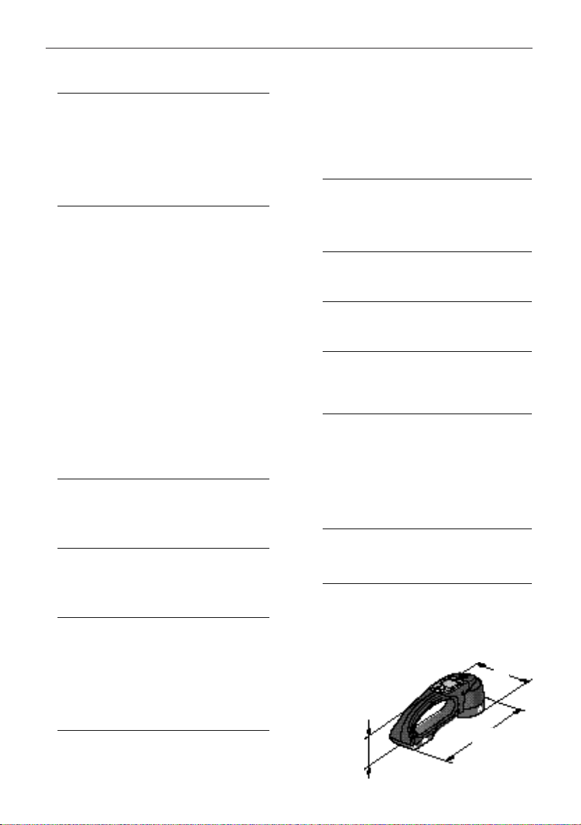
Weight
600 g (1.32 lbs) not including batteries
Dimensions (LxWxH)
280 x 95 x 86 mm (11" x 3.7" x 3.4")
Illustration with dimensions [mm]
Page 5
5
1. Product information
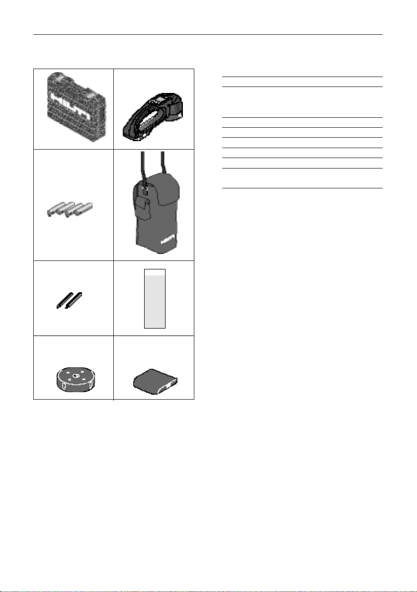
Pos. Pcs. Description
11PS 20 case
21PS 20 detector with sensor head
cover and battery compartment
cover
34AA type batteries
41PS 20 carrying pouch
52Marking pencils
61Operating manual and quick guide
71Replacement sensor head cover
81Replacement battery compartment
cover
1.5 Items supplied at time of purchase
12
34
PS 20
56
78
Page 6

6
2. Safety precautions
2. Safety precautions
2.1 Please read now!
These warnings should put PS 20 owners and
operators in the position where they can recognize possible danger in advance and avoid it,
i.e. prevent it. The owner must make sure all
operators understand and follow these warnings.
2.2 Intended purpose
The Hilti PS 20 detector is intended to be used
for the following purposes:
• detecting and depth of coverage measurement of steel reinforcement.
• detecting copper tubing and aluminum parts.
• localising live electrical cable.
The PS 20 detects electrically
conductive ferrous and non-ferrous
metals. The presence of small objects
made from such materials or the presence of objects made from other
materials cannot be ruled out.
Never attempt to open up the structure without first turning off the power
supply.
In order to guarantee reliable results,
the tool must not be used during
large temperature changes. Allow the
tool time to adjust to the surrounding
ambient temperature before use.
Measurement and evaluation of the
measurements should be performed
by properly trained personnel.
Use as intended
Misuse
They:
• have read and understood the operating
instructions
•are aware of the special features and limitations of the measuring principle used
• possess sufficient knowledge of reinforcement technology.
• Using the product without following the
instructions in the manual.
• Using the product outside of application limits
or technical specifications.
• Using the product before checking the minimum depth and offset function
settings. When set incorrectly, these will result
in misleading or incorrect measurements.
• Using in areas of electromagnetic anomalies.
This may result in
misleading or incorrect measurements.
• Using in areas where there is a danger of
explosions.
• Using in the proximity of medical
equipment. Use near such equipment may
result in disturbances or failure of it.
• Do not immerse in water or use in very heavy
rain.
• Opening parts of the product other than the
battery compartment cover.
• Modifying and/or adding parts to the product.
• Using third party accessories not explicitly
approved by Hilti.
• Using a damaged product or a product that
returns results that are not plausible.
• Measuring with very worn or dirty sensor head
cover or battery compartment cover.
• Measuring without sensor head cover or battery compartment cover
• Using without first testing the accuracy.
• Using to detect metal in humans or animals.
• Use of measuring results for purposes relating
to safety without control measures and evaluation by qualified specialists. (e.g. civil
engineers)
• Drilling very close to or on marked live electric
cables or pipes.
• Drilling on marked reinforcement deeper than
the depth displayed on the tool, also taking
into account depth accuracy specifications.
Continues
Page 7

7
2. Safety precautions
2.3 Electromagnetic Compatibility (EMC)
Electromagnetic compatibility means the capability of the PS 20 to function smoothly in an environment of electromagnetic radiation and electrostatic discharges, without causing electromagnetic interference to other equipment.
Interference caused by electromagnetic radiation
can cause disturbances in the PS 20.
Although the PS 20 meets the strict regulations
and standards which are in force in this respect,
Hilti cannot completely exclude the
possibility that interference may be
caused to the PS 20 by very intensive
electromagnetic radiation, e.g. near
welding equipment, diesel generators
etc.
Under such conditions, check measurement results for their plausibility.
The PS 20 may cause disturbance in
other equipment through electromagnetic radiation.
Although the PS 20 meets the strict
regulations and standards which are in
force in this respect, Hilti cannot completely exclude the possibility that
interference may be caused by the PS
20, e.g. in electronic measuring equipment.
Possible results of misuse
• Safety hazards to life and limb through faulty
measurement results.
• Structural damage,e.g. from drilling into
loadbearing reinforcing bars.
• Damage to the PS 20.
• Reduction of measuring accuracy.
•Warranty is null and void.
• Safety hazards to life and limb through falling
• Safety hazards to life and limb through electric shock
Misuse, Continued
Hilti products are largely manufactured from
recyclable materials. A prerequisite for recycling
is proper material separation. In many countries
Hilti is already able to accept your used unit for
recycling. Ask your Hilti representative or the
Hilti customer service.
2.5 Disposal
2.4 FCC statement (applicable in U.S.)
WARNING
This equipment has been tested and found to
comply with the limits for a Class II digital
device, pursuant to part 15 of the FCC Rules.
These limits are designed to provide reasonable
protection against harmful interference in a residential installation. This equipment generates,
uses and can radiate radio frequency energy
and, if not installed and used in accordance with
the instructions, may cause harmful interference
to radio communications. However, there is no
guarantee that interference will not occur in a
particular installation. If this equipment does
cause harmful interference to radio or television
reception, which can be determined by turning
the equipment off and on, the user is encouraged to try to correct the interference by one or
more of the following measures:
- Reorient or relocate the receiving antenna.
- Increase the separation between the equipment and receiver.
- Connect the equipment into an outlet on a circuit different from that to which the receiver
is connected.
- Consult the dealer or an experienced radio/TV
technician for help.
Component/assembly Main material Utilization
Plastic case Plastic Plastic recycling
Case Plastic Plastic recycling
Cable Copper, elastomer Scrap metal
Electronic parts Various Electronic scrap
or (sensor, charger) scrap metal
Screws, small parts Steel, brass Scrap metal
Manual Paper Waste paper
Battery, rechargeable Nickel, cadmium Batter y recycling
(observe special
local regulations)
Page 8

8
3. Operation
3. Operation
3.1 Inserting the batteries
Always replace complete battery set.
- do not mix old with new batteries
- do not use batteries from different
manufacturers or of different types.
- only used checked and undamaged
batteries.
When using rechargeable batteries only
use:
- same brand name and same model.
- of same age and charge level.
Never strike the tool in order to remove
the batteries. Always remove them by
hand.
1. Press the sides of the cover
2. Tilt it upwards
3. Remove old batteries if present
4. Insert new batteries as shown inside the battery compartment
5. Replace the cover by inserting the tab on the
cover into the slot in the tool and clicking
down into place.
Batteries will require replacement when the low
battery symbol shows on the display
- "CA” blinks in the large display and
in the function menu display.
The signal strength bar appears.
A short beep sound follows calibration
(if acoustic beep has not been turned
off).
The screen shows:
The tool is ready for
use.
4
Press On key, ”CA” blinks in the large
display and in the function menu display.
Beep
Hold the tool at least 1m away from
all metallic objects and tools or
machines that emit a large electromagnetic field.
(E.g. other PS 20s, power generators
etc).
Press the On key again:
Continues
3.2 Switching on/off and calibrating
Page 9

9
3. Operation
3.2 Switching on/off and calibrating,
Continued
Calibration:
-results in higher measuring
accuracy by taking account of the
surrounding environment
An automatic calibration request
follows if:
- the temperature changes by ± 3°C
-6 minutes after the last calibration.
When the request occurs, hold the
tool at least 1m away from all metallic
objects and machines that produce a
large electromagnetic field and press
the On key to carry out the calibration.
Then carry on working.
To switch the tool off at any time,
press the On and Function keys simultaneously.
Page 10

10
4. Working with the PS 20
Preconditions:
- tool switched on
- calibration carried out
- Minimum depth of coverage function is
inactive
4.1 Detecting reinforcement &
non-ferrous, metallic objects
Tool:
- place on surface where materials are to be
detected
- move it across the surface with a sweeping
motion. Avoid short, jerking movements as
this can result in erroneous detection.
Detecting reinforcing bar and other ferrous
objects
As a reinforcing bar is approached, the signal
strength shown on the bar increases steadily.
Determining the center of the reinforcing bar:
- the center indication light illuminates.
- the acoustic beep sounds (if active).
- signal strength bar is at a maximum.
- depth of coverage is displayed in [mm] or
[inch]
4. Working with the PS 20
Mark the position through the hole in the sensor
head using a marking pencil supplied.
Note the performance limitations and technical
specifications of the tool regarding depth measurement accuracy where depth of rebar is a
critical factor (E.g. when anchor setting).
When no depth measurement is possible,
”--” is displayed as depth of coverage.
The center, however is detected by the beep
sound, the signal strength bar at maximum and
the center indication light.
Reasons for inability to calculate depth include:
- Object is too deep to determine depth (deeper than 80mm or 3.15in)
- Object is not a standard reinforcing bar
-Iron contains a high level of impurities
The PS 20 detects electrically conductive ferrous and non-ferrous metals.
The presence of small objects made
from such materials or the presence
of objects made from other materials
cannot be ruled out.
Page 11

11
4. Working with the PS 20
4.1 Detecting objects, Continued
Detecting non-ferrous metallic objects
(copper and aluminium)
Limitations of rebar detection and depth
measurement
The problem of shading can occur
when trying to detect a second layer
of reinforcement. The top layer shades
the magnetic field. Any reinforcement
below the top layer that is shaded will
not be detected.
1.Shading
Although such a situation rarely
occurs, a reinforcing mat that lies up
to 60mm deeper than the reinforcing
bar can influence the magnetic field
produced by the tool and result in an
incorrect measurement.
Retaining the measured depth value on the
display
To retain the measured depth value on
the display after a rebar has been
detected, press and hold the On key.
This aids easy reading of the display
when working in restricted areas. After
releasing the key, the display is reset.
2.Influence of reinforcement mats on
depth measurements
Localising live electrical cable
See chapter 4.2.6
Determining the center of the pipe:
- the center indication light illuminates.
- the acoustic beep sounds (if active).
- signal strength bar is at a maximum.
- the non-ferrous metal symbol appears on the
display
Mark the position through the hole in the sensor
head using a marking pencil supplied.
Note that depth cannot be calculated.
Mark the likely area through the hole in the
sensor head using a marking pencil supplied.
To return to the metal detection mode, press the
On key.
Page 12

12
If you suspect a recalibration is required before
it is automatically requested, carry it out by:
1. Press the function key. ”CA” blinks in the
main display and in the function menu.
2. Hold the tool at least 1m away from any
metal objects.
3. Press the On key to carry out the calibration.
4. Working with the PS 20
4.2.1 Calibration
4.2 Menu Functions
Calibrating the tool enables it to ensure
accuracy regardless of temperature change or
surrounding magnetic influences.
Calibration is automatically required when the
tool is first switched on. Thereafter it will also
automatically be requested either when the temperature in the tool changes by ±3°C (+26/37°F)
or 6 minutes after the previous calibration.
You will not be able to carry on working until
this calibration is carried out. See chapter 3.2
Switching on and calibrating.
Continues
4.2.2 Setting minimum depth
of coverage
This function is used for checking minimum
concrete coverage depth for:
- quality control
- assessment of cover on concrete areas prior
to renovation
- check before drilling holes for anchors
To set the minimum coverage depth and
activate the function:
With the minimum coverage depth
set, the tool will only sound the visual
and audible alarm when reinforcing
bar is detected closer to the surface
than the defined minimum depth.
1. Select the minimum coverage function from the menu by pressing the
function key twice. The minimum
coverage icon flashes in the
function menu.
2. Press the right arrow key to set the
desired depth. Keep the key pressed
to quickly scroll to the value you
require. Use the left arrow key to
descend to a lower value if required.
Press both arrow keys together to
reset to zero.
3. Press the On key to confirm your
choice and return to the detection
mode.
The minimum coverage icon is displayed in the function menu, signifying that the function is active. Nonferrous metals will still be detected
in the normal way. This setting is
saved when the tool is switched off.
2x
Page 13

13
4. Working with the PS 20
Continues
4.2.3 Switching back light on/off
To operate in poorly lit areas (e.g. a cellar)
switch the back light on.
To switch the backlight on or off:
1. Press the function key three times.
The back light icon flashes.
2. Use the left or right arrow key to
switch the backlight on or off.
3. Press the On key to continue.
This setting is not saved when the
tool is switched off.
3x
To deactivate the function:
1. Repeat step 1 above.
2. Press both arrow key
simultaneously to reset the depth to
zero.
3. Press the On key to confirm and
continue.
The minimum coverage icon
disappears, signifying that the function
is now inactive. To ensure that the
function remains inactive switch the
tool off and then back on.
Before use, ensure that the minimum
cover setting is still valid for the area
you wish to scan. Misleading results
may be obtained if this is not done.
4.2.2 Setting minimum depth of coverage,
Continued
4.2.4 Setting the offset
Offset
The PS 20 contains a database of almost all
known standard reinforcing bars and their
magnetic characteristics. When the reinforcing
bar contains too many impurities, a false depth
of coverage may be displayed. Such problems
usually occur either in older structures or where
building standards are not enforced as a matter
of practice.
The offset function provides a solution to this
problem. However, it does rely on the operator
recognising that such a problem exists. A test
hole is drilled to the reinforcing bar and the
depth measured. Then the PS 20 is used to
measure the depth and the difference calculated. The difference will likely remain reasonably
constant for all reinforcing bar in the structure.
This difference is entered in the PS 20 and is
automatically added or subtracted from the
measured depth.
To enter the offset and activate the function:
1. Press the function key four times.
The offset icon flashes.
2. Press the left or right arrow key to
set the desired offset (Maximum
±10mm). Keep the key pressed to
quickly scroll to the value you require. Use the left arrow key to descend to a lower value if required.
Press both arrow keys together to
reset to zero.
3. Press the On key to confirm your
choice and continue.
4x
The offset icon appears in the display signifying
that the function is active. This setting is saved
when the tool is switched off.
Page 14

14
4.2.5 Switching the acoustic beep
on/off
The acoustic beep signifies either that
the centre of a reinforcing bar or
non-ferrous object has been reached.
To switch the acoustic beep on/off:
1. Press the function key five times.
The acoustic beep icon flashes.
2. Use the left or right arrow key to
switch the beep on or off.
3. Press the On key to continue.
When switched off, the corresponding symbol
appears in the display. This setting is saved
when the tool is switched off. To ensure that
the function remains inactive switch the tool
off and then back on.
5x
4. Working with the PS 20
To deactivate the function:
1. Repeat step 1 above.
2. Press both arrow key
simultaneously to reset the offset
to zero.
3. Press the On key to confirm and
continue.
The minimum coverage icon disappears, signifying that the function is
now inactive. To ensure that the function remains inactive switch the tool
off and then back on.
Before use, ensure that the offset setting is still valid for the area you wish
to scan. Misleading results may be
obtained if this is not done.
4.2.4 Setting the offset, Continued
4.2.6 Localising live electrical cable
1. Press the function key until the live
wire symbol is displayed as below.
2. Place the detector on the area of
interest. If the indication light illuminates, a cable has been found.
3. Reduce the sensitivity level by
pressing the left arrow key until the
light goes out.
4. Increase the sensitivity by one level
so that the light illuminates again
and scan the immediately surrounding area.
5. Repeat steps 3 and 4 until the area
over which the cable is found is
acceptably small.
Live electrical cable is located by first determining that a cable is nearby and then narrowing
down the area over which it is detected by reducing the sensitivity of the tool.
Use the Function menu to access the live cable
function:
Continues
To return to metal detection,
press the On key.
Page 15

15
4.2.6 Localising live electrical cable,
Continued
The following factors must be taken
into account and observed:
The cable detection function localises
the area in which a live cable lies and
gives a most likely position within this
area based on the information available.
Shielded cable and cable running in
metal conduit cannot be detected or
localised. However, metal conduit
lying within the detection range of the
PS 20 will be detected as metal and
shown accordingly on the display.
Moist or damp materials and/or a
humid atmosphere act in a similar
way to an antenna for the electric field
produced by the cable and spread it
over a large area. Therefore, live electric cables cannot be localised in
damp materials or when the surrounding air is very humid.
If a rough surface is scanned using
the live cable detection function on the
higher sensitivity levels (i.e. level 9-6),
use gentle scanning movements over
a small area. Quick, rough movements
over a large area may lead to misleading detection of live electric cables.
4. Working with the PS 20
Page 16

16
5.1 Set units to mm/in
This setting changes the units used
when displaying the depth or reinforcing bar, setting the minimum coverage depth and setting the offset. The
units may be set to millimetres or
inches and fractions of an inch. The
smallest displayed unit is 1mm or
1/32 inch.
To set the units used:
1. Ensure the tool is switched off.
2. Switch on by pressing the On and
function keys simultaneously. The
tool switches on in Settings mode
and the current unit used is displayed.
3. Use the left or right arrow key to
select the desired unit (mm or inch)
4. Press the On and function keys
simultaneously to confirm your
choice and switch the tool off.
The new settings take effect the next
time the tool is switched on.
To avoid confusion, always reset the
minimum cover and offset functions
to zero after changing units.
5. Settings menu
5. Settings menu
5.2 Test the display
All LCD segments in the display may be
activated at once to check that all are
working properly.
To test the display:
1. Ensure the tool is switched off.
2. Switch on by pressing the On and
function keys simultaneously. The
tool switches on in Settings mode
and the current unit used is displayed.
3. Press the function key to test the
display. All LCD segments are activated.
4. Press the On and function keys
simultaneously to switch the tool off.
Page 17

17
6. Care, storage, transportation / 7. Displayed notices
6.1 General care
6.2 Storage
6. Care, storage, transportation
Do not use any other liquids as they
may damage the plastic components.
Pay attention to the temperature the
tool is exposed to, especially in summer when keeping it in a vehicle.
(Storage temperatures:
-20°C to +70°C / -4°F to +158°F)
When sensor head or battery covers
are dirty:
-remove and clean.
-replace if necessary.
Signal holes will appear in the Sensor
head cover when it needs replacing.
Similarly, replace the battery cover
immediately when a hole begins to
appear. Delayed replacement may
result in irreparable damage to the tool.
Worn Sensor head and battery compartment covers can also lead to a
degradation of depth measurement
accuracy of between -1 to -4mm.
- clean with soft dry cloth. Only if necessary
dampen cloth with pure alcohol or water.
Clean and dry the tool. Do not repackage equipment until totally dry
Storage temperatures:
-20°C to +60°C / -4°F to +140°F .
Remove batteries when storing tool
for a long period of time.
Take a test measurement after long storage or
long transportation period.
7. Displayed notices
Batteries almost empty.
- replace
Sensor malfunction
Measure:
Ensure the calibration conditions have
been fulfilled as described in chapter
3.2. Switch off and back on. If error
remains, contact Hilti Service
Error codes:
E1
Temperature outside of safety range
Measure:
Switch off and allow to adjust to
surrounding temperature for one
hour. Ensure surrounding temperature
is within specifcation. Switch back on.
If error remains, contact Hilti Service
E2
Calibration cannot be carried out
Measure:
Ensure the calibration conditions have
been fulfilled as described in chapter
3.2. Switch off and back on. If error
remains, contact Hilti Service
E3
6.3 Transportation
Use the Hilti case when shipping the
tool. Always ship without batteries
inserted. In this way, any disturbance
of vehicle or aircraft systems through
unintended activation of the tool are
ruled out.
Page 18

18
9. EU-conformity declaration
Designation: PS 20
Serial numbers: 00000001 - 50000000
Year of design: 2000
-conform
We declare under sole responsibility that this
product corresponds to the following standards
or standard documents.
EG guideline 89/336/EWG and the corresponding standards DIN EN50081-1 (03.93), DIN EN
50082-2(03.95),authorized certification issued:
no. 010b/00-d.
Hilti Corporation
Armin Spiegel
Positioning Systems
Manager
Head of Business Unit
Bodo Baur
Quality Manager
Positioning Systems
Quality Manager of
Business Unit
Positioning Systems 07/2001
8. Accessories / 9. EU-conformity declaration
8. Accessories
12 red markers packaged in a plastic
storage tube
-1 replacement Sensor Head Cover
-1 replacement battery cover
Sensor Head and Battery Covers. (340807)
Markers (340806)
Replacement parts available from Hilti:
Page 19

19
10. Warranty
10. Warranty
Hilti warrants that the tool supplied is free of
defects in material and workmanship. This warranty is valid so long as the tool is operated and
handled correctly, cleaned and serviced properly
and in accordance with the Hilti Operating
Instructions, all warranty claims are made within
12 months from the date of the sale (invoice
date), and the technical system is maintained.
This means that only original Hilti consumables,
components and spare parts may be used in the
tool.
This warranty provides the free-of-charge repair
or replacement of defective parts only. Parts
requiring repair or replacement as a result of
normal wear and tear are not covered by this
warranty.
Additional claims are excluded, unless stringent national rules prohibit such exclusion. In
particular, Hilti is not obligated for direct, indirect, incidental or consequential damages,
losses or expenses in connection with, or by
reason of, the use of, or inability to use the
tool for any purpose.
Implied warranties of merchantability or fitness for a particular purpose are specifically
excluded.
For repair or replacement, send tool and/or related parts immediately upon discovery of the
defect to the address of the local Hilti marketing
organization provided.
This constitutes Hilti’s entire obligation with
regard to warranty and supersedes all prior or
contemporaneous comments and oral or written
agreements concerning warranties.
Page 20

340809
Hilti Corporation
FL-9494 Schaan
Tel.: +423 / 236 2111
Fax: +423/2362965
www.hilti.com
Hilti = reg. trademark of Hilti Corp., Schaan W2630 0801 2-Pos. 1 9 Printed in Liechtenstein © 2001
Right of technical and programme changes reserved S.E.&O.
 Loading...