

Page 1
PRA 30/
PRA 31
Bedienungsanleitung de
Operating instructions en
Mode d’emploi fr
Istruzioni d’uso it
Manual de instrucciones es
Manual de instruções pt
Gebruiksaanwijzing nl
Brugsanvisning da
Bruksanvisning sv
Bruksanvisning no
Käyttöohje fi
Οδηγιες χρησεως el
Használati utasítás hu
Instrukcja obsługi pl
Инструкция по зксплуатации ru
Návod k obsluze cs
Návod na obsluhu sk
Upute za uporabu hr
Navodila za uporabo sl
Ръководство за обслужване bg
Instrucţiuni de utilizare ro
Kulllanma Talimatı tr
ar
Lietošanas pamācība lv
Instrukcija lt
Kasutusjuhend et
ja
ko
cn
Printed: 07.07.2013 | Doc-Nr: PUB / 5140546 / 000 / 00
Page 2
MENU
1
4
11
6
8
5
8
7
2
1
3
10
9
MENU
13
cmmin
15
16
Printed: 07.07.2013 | Doc-Nr: PUB / 5140546 / 000 / 00
14
PULSEIIPOWER
17
12
18
20
19
Page 3
2
3
3
3
9
3
3
8
3
3
7
2
7
3
2
7
2
2
7
1
2
1
0
2
0
9
2
0
8
1
4
4
3
2
1
5
1
4
4
1
4
3
0
7
8
0
7
7
0
7
6
0
7
5
0
7
4
0
7
3
0
7
2
0
7
1
0
7
0
0
6
9
0
6
8
0
6
7
0
6
6
0
6
5
0
6
4
0
6
3
0
6
2
0
6
1
6
0
6
0
0
5
9
0
5
8
0
5
7
0
5
6
0
5
5
0
5
4
0
5
3
0
5
2
0
5
1
0
5
0
0
4
9
0
4
8
0
4
7
0
4
6
0
4
5
4
3
2
1
6
5
6
Printed: 07.07.2013 | Doc-Nr: PUB / 5140546 / 000 / 00
Page 4
ORIGINAL OPERATING INSTRUCTIONS
PRA 30 / PRA 31 remote control / laser receiver
It is essential that the operating instructions
are read before the tool is operated for the
en
first time.
Always keep these operating instructions to-
gether with the tool.
Ensure that the operating instructions are
with the tool when it is given to other persons.
Contents Page
1 General information 8
2Description 9
3 Technical data 9
4 Safety instructions 10
5Beforeuse 11
6 Operation 11
7 Care and maintenance 12
8Disposal 12
9 Manufacturer’s warranty - tools 13
10 FCC statement (applicable in USA) 13
11 EC declaration of conformity (original) 14
1 These numbers refer to the corresponding illustrations. The illustrations can be found on the fold-out cover
pages. Keep these pages open while studying the operating instructions.
In these operating instructions, the designation “the tool”
always refers to the PRA 30 / PRA 31 laser receiver.
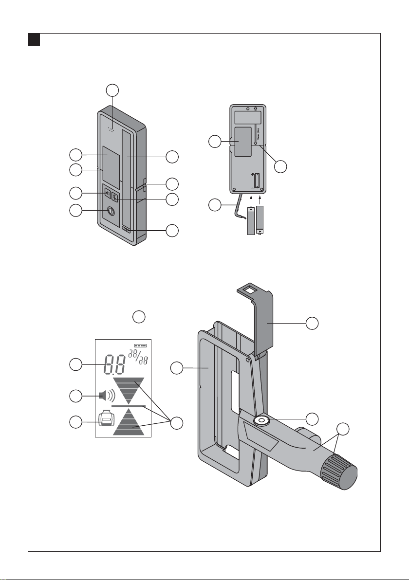
Parts, operating controls and indicators 1
PRA30/PRA31laserreceiver
On/off button
@
Audible signal button
;
Units button
=
Audible signal aperture
%
Receiving area
&
Display area, front
(
Marking notch
)
Reference plane
+
Spirit level
§
Battery compartment cover
/
Display area, rear
:
PRA30/PRA31laserreceiverdisplay
Display showing the position of the receiver relative
·
to the height of the laser plane
Exact distance of the receiver from the laser plane
$
Battery status indicator
£
Volume indicator
|
Rotating laser low energy indicator
¡
PRA 80 laser receiver holder
Protective cage
Q
Catch
W
Mounting arm with rotating grip
E
Spirit level
R
1 General information
1.1 Safety notices and their meaning
DANGER
Draws attention to imminent danger that will lead to
seriousbodilyinjuryorfatality.
WARNING
Draws attention to a potentially dangerous situation that
could lead to serious personal injury or fatality.
CAUTION
Draws attention to a potentially dangerous situation that
could lead to slight personal injury or damage to the
equipment or other property.
NOTE
Draws attention to an instruction or other useful information.
8
1.2 Explanation of the pictograms and other
information
Warning signs
General
warning
Symbols
Read the
operating
instructions
before use
Return waste
material for
recycling.
Page 5

Location of identification data on the tool
The type designation and serial number can be found on
the type identification plate on the tool. Make a note of
this data in your operating instructions and always refer
to it when making an enquiry to your Hilti representative
or service department.
Type:
Generation: 01
Serial no.:
2 Description
2.1 Use of the product as directed
The Hilti PRA 30 / 31 laser receiver is designed to detect the laser beam from rotating lasers.
Observe the information printed in the operating instructions concerning operation, care and maintenance.
Take the influences of the surrounding area into account. Do not use the tool where there is a risk of fire or explosion.
Modification of the tool or tampering with its parts is not permissible.
2.2 Features
The tool can either be held by hand or, using the corresponding holder, mounted on a measuring staff, telescopic
staff, leveling staff, wooden batten or frame etc.
2.3 Indicators
NOTE
The display of the PRA 30 / 31 laser receiver uses several symbols to indicate various modes or statuses.
en
Display showing the position of the
receiver relative to the height of the
laser plane
Battery status indicator The battery status indicator shows the remaining battery capacity.
Volume level When no volume level symbol is visible in the display, the volume level
PRE 3 battery status indicator The PRE 3 symbol is shown in the display (only if the PRA 30 / 31 is re-
Units indicator Shows the exact distance of the receiver from the laser plane in the de-
2.4 Items supplied
1 PRA30/PRA31laserreceiver
1 Operating instructions
2 Batteries (size AA cells)
1 Manufacturer’s certificate
The position of the receiver relative to the height of the laser plane is
shown by an arrow indicating the direction in which the receiver has to
be moved in order to bring it exactly into alignment with the laser.
is set to zero (off). If 1 column is shown, the volume is set to “quiet”. If
2 columns are shown, the volume is set to “normal”. If 3 columns are
shown, the volume is set to “loud”.
ceiving a signal from the PRE 3) when the PRE 3 battery requires charging.
sired measuring units.
3 Technical data
Right of technical changes reserved.
Detection range (area diameter) 2…400 m (6 to 1300 ft)
Laser plane indication area ± 0.5 mm (0.02 in)
Audible signal generator 3 volume levels plus mute setting
Liquid crystal display On both sides
Receiving range 120 mm (5 in)
9
Page 6

Center indication from top edge of casing 75 mm (3 in)
Marking notches On both sides
Automatic power-off When no beam is detected: 15 min
Dimensions 160 mm (6.5") X 67 mm (2.6") X 27 mm (0.9")
Weight (including batteries) 0.25 kg (0.6 lbs)
Power source 2 AA‑size batteries
en
Battery life (alkaline-manganese) Temperature +20°C (+68 °F): 50 h
Operating temperature range -20…+50°C (-4°F to 122°F)
Storage temperature -25…+60°C (-13 °F to 140 °F)
Protection class IP 56
in accordance with IEC 529
4 Safety instructions
4.1 Basic information concerning safety
In addition to the information relevant to safety given
in each of the sections of these operatinginstructions,
the following points must be strictly observed at all
times.
4.2.1 Electrical
4.2 General safety rules
a) Keep other persons, especially children, away
from the area in which the work is being carried
out.
b) Check the condition of the tool before use. If the
tool is found to be damaged, have it repaired at a
Hilti service center.
c) Do not render safety devices ineffective and do
not remove information and warning notices.
d) The tool must be checked at a Hilti service center
after it has been dropped or subjected to other
mechanical stresses.
e) If mounting on an adapter, check that the tool is
fitted correctly.
f) To avoid measurement errors, the receiving area
must be kept clean.
g) Although the tool is designed for the tough condi-
tions of jobsite use, as with other optical and electronic instruments (e.g. binoculars, spectacles,
cameras) it should be treated with care.
h) Although the tool is protected to prevent entry
of dampness, it should be wiped dry each time
before being put away in its transport container.
i) To avoid hearing damage, hold the tool as far
away as possible from your ear (and other persons’ ears).
a) Keep the batteries out of reach of children.
b) Do not allow the batteries to overheat and do not
expose them to fire. The batteries may explode or
release toxic substances.
c) Do not charge the batteries.
d) Do not solder the batteries into the tool.
e) Do not discharge the batteries by short circuiting
as this may cause them to overheat and present
a risk of personal injury (burns).
f) Do not attempt to open the batteries and do not
subject them to excessive mechanical stress.
4.3 Proper organization of the work area
a) Avoid unfavorable body positions when working
on ladders or scaffolding. Make sure you work
fromasafestanceandstayinbalanceatall
times.
b) Measurements taken through or from panes of glass
or through other objects may be inaccurate.
c) Use the tool only within its specified limits.
d) Use of the telescopic staff in the vicinity of over-
head high voltage cables is not permissible.
4.4 Electromagnetic compatibility
Although the tool complies with the strict requirements
of the applicable directives, Hilti cannot entirely rule out
the possibility of the tool being subject to interference
caused by powerful electromagnetic radiation, leading
to incorrect operation. Check the accuracy of the tool
by taking measurements by other means when working
under such conditions or if you are unsure. Likewise, Hilti
cannot rule out the possibility of interference with other
devices (e.g. aircraft navigation equipment).
10
Page 7

5Beforeuse
5.1 Inserting the batteries
CAUTION
Do not use damaged batteries.
6Operation
6.1 Switching the tool off and on
Press the on/off button.
6.2 Working with the tool
The PRA 30 / 31 laser receiver can be used at distances
(radiuses) of up to 200 m (650 ft). The laser beam is
indicated visually and by an audible signal.
6.2.1 Using the laser receiver as a hand-held tool
1. Press the on/off button.
2. Hold the PRA 30 / 31 directly in the plane of the
rotating laser beam.
The laser beam is indicated by visual and audible
signals.
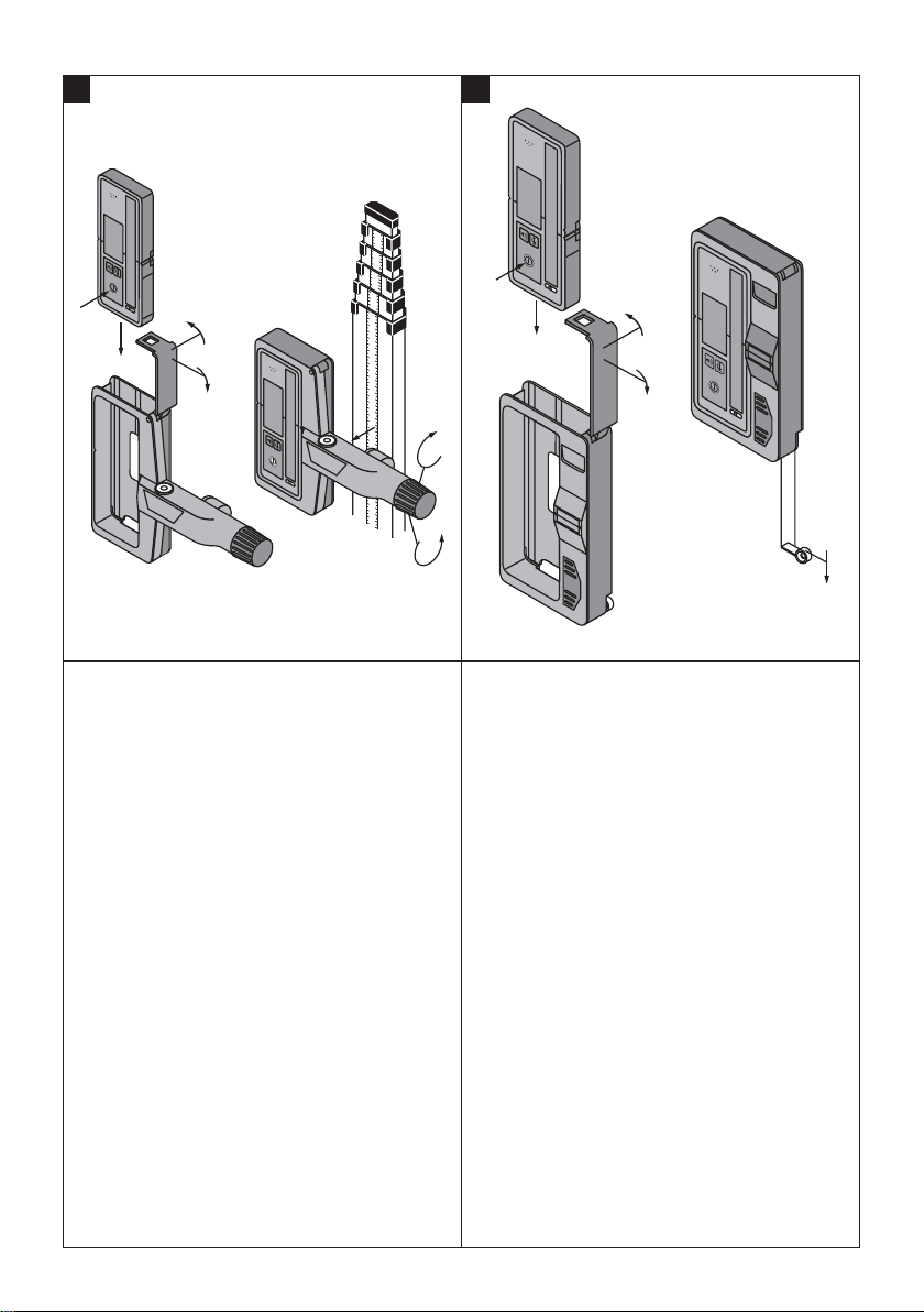
6.2.2 Working with the laser receiver in the PRA 80
receiver holder 2
1. Open the catch on the PRA 80.
2. Insert the PRA 30 / 31 laser receiver in the PRA 80
laser receiver holder.
3. Close the catch on the PRA 80.
4. Switch the laser receiver on by pressing the on / off
button.
5. Rotate the grip to bring it into the open position.
6. Secure the PRA 80 receiver holder on the telescopic
staff or leveling staff by turning the rotating grip.
7. Hold the PRA 30 / 31 with the receiving window
directly in the plane of the rotating laser beam.
The laser beam is indicated by visual and audible
signals.
DANGER
Do not mix old and new batteries. Do not mix batteries
of different makes or types.
NOTE
Only batteries recommended by Hilti may be used to
power the tool.
6.2.3 Working with the PRA 81 3
1. Open the locking mechanism on the PRA 81.
2. Insert the PRA 30 / 31 laser receiver in the PRA 81
height transfer device.
3. Close the locking mechanism on the PRA 81.
4. Switch the laser receiver on by pressing the on / off
button.
5. Hold the PRA 30 / 31 with the receiving window
directly in the plane of the rotating laser beam.
The laser beam is indicated by visual and audible
signals.
6. Use the measuring tape to measure the desired
offset distance.
6.2.4 Menu options
When switching the PRA 30 / 31 on, press and hold the
on / off button for two seconds.
Themenuisthenshowninthedisplay.
Use the “units” button to switch between metric and
imperial units.
Use the “volume” button to assign the higher-pitched
signal to the upper or lower area of the receiving window.
To save the settings, switch the PRA 30 / PRA 31 off.
6.2.5 Setting the measuring unit
The “units” button can be used to set the desired measuring unit according to the country of use (mm / cm / off)
or (¹⁄₈in / ¹⁄₁₆in / off).
6.2.6 Setting the volume of the audible signal
The tool is set to “normal” volume when switched on.
The volume can be adjusted from “normal” to “loud” by
pressing the audible signal button. Press the button again
to switch the signal off and press it once more to set the
signal to “quiet”.
en
11
Page 8

7 Care and maintenance
7.1 Cleaning and drying
1. Blow dust off the surfaces.
2. Do not touch the display areas or the receiving
window with the fingers.
3. Use only a clean,soft cloth for cleaning. If necessary,
en
moisten the cloth slightly with pure alcohol or a little
water.
NOTE Do not use any other liquids as these may
damage the plastic components.
4. Observe the temperature limits when storing your
equipment. This is particularly important in winter
/summeriftheequipmentiskeptinsideamotor
vehicle (25°C to +60°C / -22°F to +140°F).
the equipment only once it has dried completely and then
store it in a dry place.
Check the accuracy of the equipment before it is used
after a long period of storage or transportation.
Remove the batteries from the tool before storing it for a
long period. Leaking batteries may damage the tool.
7.3 Transport
Use the Hilti toolbox or packaging of equivalent quality
fortransportingorshippingyourequipment.
DANGER
Always remove the batteries before transporting the
tool.
7.2 Storage
Remove the tool from its case if it has become wet.
The tool, its carrying case and accessories should be
cleaned and dried (at maximum 40°C / 104°F). Repack
7.4 Hilti calibration service
We recommend that the tool is checked by the Hilti calibration service at regular intervals in order to verify its
reliability in accordance with standards and legal requirements.
8 Disposal
DANGER
Improper disposal of the equipment may have serious consequences:
The burning of plastic components generates toxic fumes which may present a health hazard.
Batteries may explode if damaged or exposed to very high temperatures, causing poisoning, burns, acid burns or
environmental pollution.
Careless disposal may permit unauthorized and improper use of the equipment. This may result in serious personal
injury, injury to third parties and pollution of the environment.
Most of the materials from which Hilti tools or appliances are manufactured can be recycled. The materials must
be correctly separated before they can be recycled. In many countries, Hilti has already made arrangements for
taking back old tools and appliances for recycling. Ask Hilti customer service or your Hilti representative for further
information.
For EC countries only
Do not dispose of electrical appliances together with household waste.
In observance of the European Directive on waste electrical and electronic equipment and its imple-
mentation in accordance with national law, electrical appliances that have reached the end of their life
must be collected separately and returned to an environmentally compatible recycling facility.
Dispose of the batteries in accordance with national regulations. Please help us to protect the environment.
12
Page 9

9 Manufacturer’s warranty - tools
Hilti warrants that the tool supplied is free of defects in
materialandworkmanship.Thiswarrantyisvalidsolong
as the tool is operated and handled correctly, cleaned
and serviced properly and in accordance with the Hilti
Operating Instructions, and the technical system is maintained. This means that only original Hilti consumables,
components and spare parts may be used in the tool.
This warranty provides the free-of-charge repair or replacement of defective parts only over the entire lifespan
of the tool. Parts requiring repair or replacement as a
result of normal wear and tear are not covered by this
warranty.
10 FCC statement (applicable in USA)
CAUTION
This equipment has been tested and found to comply with
the limits for a class B digital device, pursuant to part 15
of the FCC rules. These limits are designed to provide
reasonable protection against harmful interference in a
residential installation. This equipment generates, uses,
and can radiate radiofrequency energy and, if not installed
and used in accordance with the instructions, may cause
harmful interference to radio communications.
However, there is no guarantee that interference will not
occur in a particular installation. If this equipment does
cause harmful interference to radio or television reception, which can be determined by turning the equipment
Additional claims are excluded, unless stringent national rules prohibit such exclusion. In particular, Hilti
is not obligated for direct, indirect, incidental or consequential damages, losses or expenses in connection with, or by reason of, the use of, or inability to
use the tool for any purpose. Implied warranties of
merchantability or fitness for a particular purpose are
specifically excluded.
For repair or replacement, send the tool or related parts
immediately upon discovery of the defect to the address
of the local Hilti marketing organization provided.
This constitutes Hilti’s entire obligation with regard to
warranty and supersedes all prior or contemporaneous
comments and oral or written agreements concerning
warranties.
on and off, the user is encouraged to try to correct the
interference by one or more of the following measures:
Re-orient or relocate the receiving antenna.
Increase the distance between the equipment and receiver.
Consult the dealer or an experienced TV/radio technician
for assistance.
NOTE
Changes or modifications not expressly approved by the
party responsible for compliance could void the user’s
authority to operate the equipment.
en
13
Page 10

11 EC declaration of conformity (original)
Designation: Remote control / laser
Type: PRA 30 / PRA 31
Generation: 01
Year of design: 2008/2009
en
We declare, on our sole responsibility, that this product
complies with the following directives and standards:
2011/65/EU, 2006/95/EC, 2004/108/EC.
Hilti Corporation, Feldkircherstrasse 100,
FL‑9494 Schaan
Paolo Luccini Matthias Gillner
Head of BA Quality and Process Management
Business Area Electric Tools & Accessories
01/2012 01/2012
Executive Vice President
Business Area Electric
receiver
Tools & Accessories
Technical documentation filed at:
Hilti Entwicklungsgesellschaft mbH
Zulassung Elektrowerkzeuge
Hiltistrasse 6
86916 Kaufering
Deutschland
14
Page 11

*368229*
368229
Hilti Corporation
LI-9494 Schaan
Tel.:+423 /234 21 11
Fax:+423 /234 2965
www.hilti.com
Hilti = registered trademark of Hilti Corp., Schaan
W 3603 | 0313 | 00-Pos. 1 | 1
Printed in Germany © 2013
Right of technical and programme changes reserved S. E. & O
.
368229 / A2
Printed: 07.07.2013 | Doc-Nr: PUB / 5140546 / 000 / 00
 Loading...