

Page 1

PR 60 / PA 350
Operating instructions 1– 50
Mode d’emploi 51–100
GB
F
*338416*
338416
Page 2

2
Operating Instructions PR 60 / PA 350
Symbols used
The symbols used in these operating instructions have the
following meanings:
WARNING
Usage risk or incorrect use which could lead to severe personal
injury of a fatal accident.
CAUTION
Usage risk or incorrect use which could lead to only minor
personal injury but considerable damage to property or the
environment.
Usage information which helps the user to employ the
instrument efficiently and in a technically correct manner.
Besides the instructions for use, these operating instructions
also contain important safety information (see “Safety
instructions” section).
PR 60 rotating laser / PA 350 detector
Please read these operating instructions carefully before
operating the tool for the first time. Make the instructions
available to all other users so that they can be read before the
tool is operated.
Always keep these operating instructions with the tool.
The operating instructions should always be with the tool
when it is given to other persons.
Page 3

3
Contents
Contents Page
1. Product information. . . . . . . . . . . . . . . . . . . . . . . . . . . . . . . . . . . . . . . . . . . . 4
Description of the PR 60 . . . . . . . . . . . . . . . . . . . . . . . . . . . . . . . . . . . . . . . . .4
Main parts of the PR 60 . . . . . . . . . . . . . . . . . . . . . . . . . . . . . . . . . . . . . . . . . .6
PR 60 control panel . . . . . . . . . . . . . . . . . . . . . . . . . . . . . . . . . . . . . . . . . . . . .7
PR 60 quick-start instructions . . . . . . . . . . . . . . . . . . . . . . . . . . . . . . . . . . . .10
PR 60 technical data . . . . . . . . . . . . . . . . . . . . . . . . . . . . . . . . . . . . . . . . . . .11
Description of the PA 350 . . . . . . . . . . . . . . . . . . . . . . . . . . . . . . . . . . . . . . .14
PA 350 technical data . . . . . . . . . . . . . . . . . . . . . . . . . . . . . . . . . . . . . . . . . .18
Items supplied . . . . . . . . . . . . . . . . . . . . . . . . . . . . . . . . . . . . . . . . . . . . . . . .20
2. Safety precautions. . . . . . . . . . . . . . . . . . . . . . . . . . . . . . . . . . . . . . . . . . . . 21
Intended uses . . . . . . . . . . . . . . . . . . . . . . . . . . . . . . . . . . . . . . . . . . . . . . . .21
Examples of misuse . . . . . . . . . . . . . . . . . . . . . . . . . . . . . . . . . . . . . . . . . . . .22
Laser classification . . . . . . . . . . . . . . . . . . . . . . . . . . . . . . . . . . . . . . . . . . . .24
Electromagnetic compatibility (EMC) . . . . . . . . . . . . . . . . . . . . . . . . . . . . . . .25
Care, storage and transportation . . . . . . . . . . . . . . . . . . . . . . . . . . . . . . . . . .26
Disposal . . . . . . . . . . . . . . . . . . . . . . . . . . . . . . . . . . . . . . . . . . . . . . . . . . . . .27
3. Operation and use . . . . . . . . . . . . . . . . . . . . . . . . . . . . . . . . . . . . . . . . . . . . 29
Inserting the batteries (PR 60) . . . . . . . . . . . . . . . . . . . . . . . . . . . . . . . . . . . .29
Inserting the batteries (PA 350) . . . . . . . . . . . . . . . . . . . . . . . . . . . . . . . . . . .30
Setting up and operating the tool . . . . . . . . . . . . . . . . . . . . . . . . . . . . . . . . . .30
4. Checks . . . . . . . . . . . . . . . . . . . . . . . . . . . . . . . . . . . . . . . . . . . . . . . . . . . . .38
Checking horizontal rotation . . . . . . . . . . . . . . . . . . . . . . . . . . . . . . . . . . . . .39
Adjustment . . . . . . . . . . . . . . . . . . . . . . . . . . . . . . . . . . . . . . . . . . . . . . . . . . .41
Checking oblique error . . . . . . . . . . . . . . . . . . . . . . . . . . . . . . . . . . . . . . . . . .43
5. Accessoires . . . . . . . . . . . . . . . . . . . . . . . . . . . . . . . . . . . . . . . . . . . . . . . . . 45
6. FCC statement (applicable in U.S.) . . . . . . . . . . . . . . . . . . . . . . . . . . . . . . 47
7. EC declaration of conformity . . . . . . . . . . . . . . . . . . . . . . . . . . . . . . . . . . . 49
8. Warranty . . . . . . . . . . . . . . . . . . . . . . . . . . . . . . . . . . . . . . . . . . . . . . . . . . . . 50
Page 4

4
1. Product Information
Rotating head
Control
panel
Grip
Laser beam
(invisible)
1. Product Information
Description of the PR 60
PR 60 rotating laser - for quick and precise horizontal alignment
Battery
compartment
Page 5

5
1. Product Information
The Hilti PR 60 is a rotating laser level with a rotating, invisible
laser beam.
Features
- Using the PR 60 rotating laser, a single person can level any
plane quickly and with great accuracy - always in conjunction
with the PA 350 detector.
- The speed of rotation of the PR 60 is 600 rpm (revolutions per
minute) when the tool is levelled.
- Automatic levelling (within ±5°):
Levelling takes place automatically after the tool is switched
on by way of two built-in servo motors for the x and y axes.
The beam switches on once the specified accuracy and full
speed of rotation has been reached.
- The built-in liquid compensation system ensures high
accuracy and optimum beam stabilisation over the entire
service life of the unit.
- LEDs indicate the current operating status.
- Built-in shock warning function: The tool switches to warning
mode should it be knocked off level during operation (vibration
/ impact); the auto-levelling and shock warning LEDs blink and
the speed of rotation of the head is reduced to 150 rpm.
- Automatic cut-out: The laser beam does not switch on and the
auto-levelling LED blinks when the tool is set up outside its
self-levelling range or when rotation is blocked mechanically.
- The tool can be mounted on a tripod with 5/8” thread or
placed directly on a steady supporting surface.
- Easy to operate, robust construction, reasonable weight.
Description of the PR 60, continued
Page 6

6
1. Product Information
Main parts of the PR 60
No. Designation
1 Rotating head
2 Laser exit aperture
3 Adjustment apertures
4 Control panel
5 Battery compartment with locking knob
6 Baseplate with grip and 5/8" thread
1
2
4
5
6
3
Page 7

7
1. Product Information
PR 60 control panel
No. Designation
1 Auto-levelling LED
2 ON / OFF button
3 Shock warning ON / OFF button
4 Shock warning LED
5 Battery capacity LED
1
2
5
4
3
ON / OFF button
For switching the tool on / off. After switching on, the tool begins
the automatic levelling process and the auto-levelling LED
blinks. Battery capacity is also indicated.
Auto-levelling LED
Blinking rapidly automatic levelling started
Blinking slowly levelling almost complete
Off tool is levelled / operating correctly
Page 8

8
1. Product Information
PR 60 control panel, continued
Shock warning LED
During operation, the tool monitors its own steady position. The
laser switches off and the tool indicates a warning should it
suddenly be brought out of level due to vibration or an impact:
The auto-levelling LED and shock warning LED blink rapidly.
The shock warning LED lights continuously (red) when the shock
warning function has been deactivated.
Shock warning button
- The shock warning function is activated each time after the
tool is switched on and levelling has been achieved.
- To deactivate the shock warning function, press the button
twice in quick succession. The shock warning LED then lights
continuously (Red).
- The shock warning function can be reactivated by pressing the
button once or switching the tool on again. The LED then no
longer lights.
CAUTION
It is possible that no shock warning is given if the height of the
tripod drops very slowly and parallel to the level at which it was
set. The level should thus be checked at regular intervals.
Page 9

9
Battery capacity LED
In order to save battery power, the battery capacity LED is active
for approx. 1 minute only after switching on the tool and after a
change in the information indicated (change in remaining battery
capacity).
Indication of remaining battery capacity (in 4 stages)
- All LEDs light:
Maximum battery capacity (4.6 V or more)
- 2 LEDs light:
Between 4.0 and 4.6 V
- 1 LED blinks:
3.3 to 4.0 V: The tool may continue to be operated for only a
short time; replace the batteries.
- The LEDs blink alternately as long as some voltage is still
available:
Batteries exhausted: The tool no longer operates.
1. Product Information
PR 60 control panel, continued
Page 10

10
1. Product Information
PR 60 quick-start instructions
1. Set up the tripod (e.g. PA 910) on a steady, approximately
horizontal surface. Take care to ensure that as many
measuring points as possible can be reached.
2. Mount the PR 60 correctly on the tripod.
3. Switch on the tool.
The auto-levelling LED blinks, the shock warning function is
activated and the remaining battery capacity indicated.
Levelling takes place automatically (under the most
unfavourable conditions, within 90 sec.), the auto-levelling
LED extinguishes and the head begins to rotate at the
operating speed of 600 rpm.
The laser beam does not switch on and the auto-levelling LED
blinks when the tool is set up outside its self-levelling range
(±5°) or when rotation is blocked mechanically.
To remedy this, proceed as follows:
- Switch off the PR 60
- Level the tripod approximately by hand
- Switch on the PR 60 again
4. Attach the PA 350 detector correctly to the surveyor’s rod.
Switch on the detector and begin work.
When working in an unsteady environment (vibration,
wind,...), it may be of advantage to switch off the PR 60’s
shock warning function. In this case, however, unintentional
displacement of the tool will be ignored. The tool then relevels
itself automatically. The level should thus be checked at
regular intervals.
Page 11

11
PR 60 technical data
Measurement range
1 - 150 m [500 ft] (radius) with PA 350 detector
Accuracy ± 0.7 mm @ 10 m (at 24°C)
[± 0.028 inch @ 32.8 ft]
Speed of rotation [600 rpm]
600 rpm (operating speed)
Laser Invisible, 795 nm (laser class 1) (EN60825-1)
Class I (FDA21 CFR); output power: < 1mW
Levelling
Self-levelling within ±5°, LED indicator
Operating indicators
- auto-levelling LED
- battery condition LED
- shock warning LED
Shock warning
When the tool is brought out of level during operation as a result
of an impact or vibration:
- rotation stops
- the auto-levelling and shock warning LEDs both blink
Power supply
4 type-D alkaline batteries (standard) or
4 type-D NiCd rechargeable batteries (in conjunction with the
accessory charger set)
1. Product Information
Page 12

12
1. Product Information
PR 60 technical data, continued
Battery life at 20°C [+68°F]
Alkaline: > 140 h
Ni-Cd: > 60 h
Tripod thread
5/8 " x 11
Operating temperature
-20° ... +50°C [-4°F ... +122°F]
Storage temperature
-30° ... +60°C dry [-22°F ... +140°F]
Protection class
IP 56 (IEC 529),
Protection against dust and heavy water spray
Weight 3.0 kg (6.6 lbs) including 4 batteries
Dimensions
260(L) x 151(W) x 242(H) mm
[10.2(L) x 5.9(W) x 9.5(H) inches]
Page 13
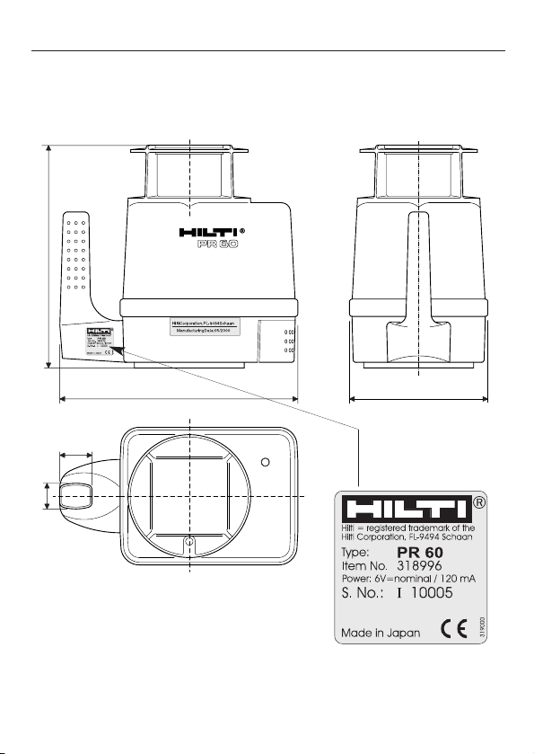
13
PR 60 technical data, continued
Dimensions [mm]
1. Product Information
242.4
260 151.3
35
28
Page 14

14
1. Product Information
Description of the PA 350
3
1
2
No. Designation
1 Display (front)
2 Detection window
3 Control panel
Page 15

15
The Hilti PA 350 detector is designed to detect the laser beam
emitted by rotating lasers.
Features
- When a laser beam strikes the detection window, a liquid
crystal display indicates whether the detector lies below,
above or exactly in the reference plane (at the height of the
mark).
- The visual indicators (arrows) and acoustic signal help the
user to find the reference plane.
- The detector can be used on its own or it may be mounted on
the telescopic rod or attached to a wooden batten or frame
etc. using a suitable holder.
- To assist in finding the laser plane, one of two laser plane
indicator area widths (narrow or standard) may be selected. A
bar is shown in the display when the laser plane is within
these areas. (Please refer to the section on “Compensation”.)
- Automatic cut-out
Battery power is switched off automatically when no laser
beam is detected over a period of more than approx. 30
minutes.
- Indicates the status of the PR60: The PA 350 detects the
warnings transmitted by the PR 60 and indicates «shock
warning» as well as «low batteries».
1. Product Information
Description of the PA 350, continued
Page 16

16
1. Product Information
Description of the PA 350, continued
1
2
4
3
8
7
5
6
11
9
10
Detailed illustration:
The display
12
14
13
16
15
Page 17

17
No. Designation
1 ON / OFF button
2 Button for adjusting the laser plane indicator width
3 Button for adjusting the acoustic signal
4 Acoustic signal emission aperture
5 Detection window
6 Display, front (see detailed illustration)
7 Marking notch
8 Reference plane
9 Battery cover
10 Thread for fastening the detector to accessory
items
11 Display, rear (see detailed illustration)
12 Indication of selected tolerance (standard or
narrow)
13 Indication of position of detector relative to
laser plane
14 Battery condition indicator (detector)
15 Battery condition indicator (rotating laser)
16 Shock warning indicator (rotating laser)
1. Product Information
Description of the PA 350, continued
Page 18

18
1. Product Information
Operating range
1-150 / 200 m (3-500 / 650ft); depending on power output of the
rotating laser
Width of laser plane indicator area
Narrow ±1mm (0.04 inches); tolerance ±0.3mm (0.012 inches)
Standard ±2mm (0.08 inches); tolerance ±0.6mm (0.024 inches)
Accuracy of sensor position in housing
±0.5mm (<1/64inch)
Acoustic indicator
2 volume levels or silent operation
Liquid crystal display
Both sides
Detection area
50mm (2 inches)
Centre indicator, from top edge of housing
40mm (1 9/16 inch)
Marking notches
On both sides
Battery low warning
Yes
PA 350 technical data
Page 19

19
1. Product Information
PA 350 technical data, continued
Automatic cut-out
The detector switches itself off automatically after 30 minutes
when no laser beam is detected.
Dimensions 165 x 78 x 26mm (6.5 x 3.2 x 1inches)
Weight 250 g (0.55 lbs) including batteries
Power supply
9 V block battery
Battery life
With alkaline batteries: 50h
Operating temperature
-20° ... +50°C dry [-4°F ... +122°F]
Storage temperature
-40°C to +63°C dry (-40°F to +145°F)
Page 20

20
1. Product Information
Items supplied
No. Qty. Designation
1 1 PR 60 rotating laser
2 4 Alkaline batteries for the PR 60
3 1 Desiccant
4 1 Operating instructions
5 1 Carrying case
6 1 Battery for the PA 350
7 1 PA 350 detector
8 1 Adjusting wrench
1
6
5
8
2
4
7
3
Page 21

21
2. Safety precautions
2. Safety precautions
The PR 60 and PA 350 are designed to be used for determining
and checking horizontal alignment and height differences in
applications such as:
- Transferring datum marks and height marks
- Excavation work
- Alignment of concrete formwork
- Concreting work for foundations, floors and ceilings
Hilti offers various accessories to facilitate use of the PR 60 (see
section “5. Accessories”).
Intended uses
Page 22

22
2. Safety precautions
Examples of misuse
WARNING
- Use of the product without prior instruction
- Use of the product outside its operating limits
- Conversions or modifications to the product
- Rendering safety devices ineffective or removing notices and
warning signs
- Inadequate safety measures at the location where the product
is in use (e.g. levelling or alignment work at a roadside etc.)
- Keep the tool out of reach of children. Laser tools do not
belong in children’s hands.
- Avoid unusual body positions when carrying out alignment
work from ladders. Make sure that your stance is secure and
always stay in balance.
- The battery must be insulated or removed from the tool when
it is shipped.
- The tools are not designed for use in environments where
there is a risk of explosion.
Page 23

23
2. Safety precautions
Examples of misuse, continued
CAUTION
- Check the tool for possible damage before use. If the tool is
damaged, have it repaired at a Hilti service centre.
- If the tool has been dropped or subjected to other mechanical
forces, its accuracy should be checked. For safety’s sake,
check its accuracy before each use.
- When using adaptors, always ensure that the tool is screwed
on securely.
- When the tool is brought into a warmer environment from a
very low temperature, or vice versa, it should be allowed to
become acclimatised to the ambient temperature before it is
operated.
- Measurements taken through panes of glass or other objects
may be inaccurate.
- To avoid inaccurate measurements, always keep the laser
beam exit windows clean.
- Although the tool is designed for use under arduous
conditions on construction sites, like any other item of optical
equipment (e.g. binoculars, spectacles), it should be handled
with care.
- Although the tool is designed to prevent the entry of moisture,
it should be wiped dry before being put away in its carrying
case.
Page 24

24
The PR 60 rotating laser complies with laser class 1, based on
the EN60825-1 standard and class I based on FDA 21 CFR.
These devices may be used without further protective measures.
WARNING
Do not look directly into the laser exit aperture.
WARNING
The tools may be repaired only at Hilti service centres. Laser
radiation in excess of class 1 may be emitted if the housing of
the PR 60 is opened without due care and without observing the
applicable safety precautions.
Laser warning based on EN60825-1
Laser warning for USA based on FDA 21 CFR
2. Safety precautions
Laser classification
Page 25

25
2. Safety precautions
Electromagnetic compatibility (EMC)
Electromagnetic compatibility refers to the ability of the Hilti
PR 60 to function correctly in an environment where it is
exposed to electromagnetic radiation and electrostatic discharge,
without causing electromagnetic interference to other devices.
WARNING
There may be a possibility of interference to other equipment
due to electromagnetic radiation.
Although the Hilti PR 60 complies with the strict requirements of
the relevant directives and standards, Hilti cannot entirely rule
out the possibility of interference with other equipment.
CAUTION
Measurements may exceed tolerances where interference is
caused by powerful electromagnetic radiation.
Although the Hilti PR 60 complies with the strict requirements of
the relevant directives and standards, Hilti can not entirely rule
out the possibility of the PR 60 being subject to interference
caused by very intense electromagnetic radiation, e.g. in the
immediate vicinity of radio transmitters, radio communication
equipment, diesel generators etc.
Check the readings for plausibility when the tool is used under
these conditions.
Page 26

26
Cleaning and drying
- Blow dust off the lenses.
- Don’t touch the glass with your fingers.
- Use only clean, soft cloths for cleaning. If necessary, moisten
the cloth slightly with pure alcohol or a little water.
Do not use any other liquids as these may damage the plastic
components.
Observe the temperature limits when storing your equipment.
This is particularly important in summer if the equipment is kept
inside a motor vehicle (-30°C to +60°C / -22°F to +140°F).
Storage
- Remove the tool from its case if it has become wet. The tool,
its carrying case, and accessories should be cleaned and
dried (at a maximum temperature of 40°C / 108°F). Put the
equipment back into its case only when it is completely dry.
- Check the accuracy of the equipment by taking test
measurements before it is used after a long period of storage
or transportation.
Transportation
Your equipment should be shipped in the Hilti shipping carton or
packaging of similar quality.
Always remove the batteries before shipping.
2. Safety precautions
Care, storage and transportation
Page 27

27
2. Safety precautions
Disposal
WARNING
Improper disposal of the equipment may lead to the following:
- Burning of plastic components generates toxic fumes which
may present a health hazard.
- If damaged or exposed to very high temperatures, batteries
may explode, causing poisoning, burns, acid burns or
environmental pollution.
- Careless disposal enables unauthorised persons to make
improper use of the equipment. This may lead to serious
injury to themselves or to a third party and to pollution of the
environment.
Most of the materials from which Hilti tools are manufactured
can be recycled.
The materials must be correctly separated before they can be
recycled.
In many countries, Hilti has already made arrangements for
taking back old tools for recycling.
Please ask your Hilti customer service department or Hilti
representative for further information. Please help to protect and
maintain our environment.
Page 28

28
2. Safety precautions
Disposal, continued
Part, assembly Main material Recycling
Housing, Plastic Plastics recycling
carrying case
Control panel, Plastic Plastics recycling
display
Liquid Metal and Scrap metal,
compensator oil old oil
Electronics Various Electronics scrap
Screws, Steel Scrap metal
small parts
Page 29

29
3. Operation and use
3. Operation and use
1 Turn lever A from LOCK to OPEN.
2 Pull the battery holder out of the tool.
3 Remove the old batteries and dispose of them in accordance
with regulations.
4 Insert new batteries, taking care to observe correct polarity.
5 Push the battery holder into the tool.
6 Turn the lever to the LOCK position.
Inserting the batteries (PR 60)
1 LED blinks: Replace the batteries
The LEDs blink alternately as long as some voltage is present:
Batteries are discharged; the unit cannot be operated.
Inserting new batteries
A
1
2
3
4
5
6
Page 30

30
3. Operation and use
Inserting the batteries (PA 350)
The following symbols indicate the condition of the battery in the
PA 350:
Battery voltage is adequate.
Battery voltage is low.
The tool will, nevertheless, continue to function (symbol
alternates between charged and discharged).
Battery voltage is inadequate.
Please replace the battery.
To replace / insert a new battery, open the battery compartment.
Remove the used battery and dispose of it in accordance with
regulations. Insert the supplied 9 V block battery (or a new
battery) and then push the battery holder back into the tool.
Always replace the complete set of batteries!
- Do not mix old and new batteries.
- Do not use batteries of different makes or of different types.
The «low batteries» warning is detected by the PA 350 and
indicated: The symbol then blinks.
To deactivate the warning on the PA 350: Press and hold the
"Buzzer" button an then press the «ON» button to switch
on.
Inserting the batteries (PR 60)
Page 31

31
3. Operation and use
Setting up and operating the tool
1. Place the tripod (e.g. PA 910) on a steady, approximately
horizontal surface. Take care to ensure that as many
measuring points as possible can be reached.
Open the quick-release clamps on the tripod legs, pull the legs
out to the required height and then close the clamps. Press
the points of the tripod legs into the ground by applying foot
pressure, thus ensuring that the tripod stands securely. When
applying foot pressure to the tripod legs, ensure that the force
applied acts towards the point of the leg.
Page 32

32
3. Operation and use
Setting up and operating the tool, continued
When setting up the tripod, take care to ensure that the tripod
top plate is approximately horizontal.
2. Mount the PR 60 correctly on the tripod.
Page 33

33
3. Switch on the PR 60.
The auto-levelling LED blinks, the shock warning function is
activated and the remaining battery capacity is indicated.
Levelling takes place automatically (within max. 90 sec.), the
auto-levelling LED extinguishes and the rotating head begins
to rotate at the operating speed of 600 r.p.m.
The laser beam will not switch on and the auto-levelling LED
will begin to blink if the tool is set up outside its self-levelling
range (± 5°)or if rotation is blocked mechanically.
To remedy this problem, switch off the PR 60, bring the tripod
into an approximately horizontal position and then switch on
the PR 60 once again.
4. Attach the PA 350 detector correctly to the telescopic rod or
surveyor’s rod and switch it on at the ON / OFF button.
< 90 s
3. Operation and use
Setting up and operating the tool, continued
Page 34

34
3. Operation and use
Setting up and operating the tool, continued
5. Use the sensitivity button to select the desired laser plane
indicator area width.
One of the following symbols is shown in the display:
Laser plane indicator area width
standardnarrow
6. Optional adjustments
Use the button for adjusting the acoustic signal to set the
desired volume level.
The standard volume level is set when the tool is switched on.
Each press of the button adjusts the volume level of the
acoustic signal in the following sequence: normal / loud / off.
7. Hold the PA 350 detector within the plane of the invisible,
rotating laser beam.
The laser beam will be indicated visually and by the acoustic
signal.
Page 35

35
Depending on the position of the laser beam, the following
information will be displayed:
PA 350
PR 60
3. Operation and use
Setting up and operating the tool, continued
* Depends on the sensitivity setting
Page 36

36
Indication of the direction of a “lost” beam
When the PA 350 detection window is moved out of the laser
plane, the direction in which the tool should be moved to bring it
back into the plane of the beam is indicated for approx. 20
seconds, as follows:
3. Operation and use
Setting up and operating the tool, continued
Compensation
To make it easier to find the laser plane, one of two laser plane
indicator area-width ranges (narrow or standard) may be
selected. A centre bar is shown in the display when the laser
plane is within these ranges.
For very high accuracy
To further increase the accuracy of the detector, compensation
readings may be taken to eliminate the tolerance range of the
selected laser indicator area width. To do this, the detector is
moved through the plane of the laser beam and the point
marked at which the centre bar is indicated. The detector is then
moved further in the same direction until the centre bar again
disappears. A second mark should be made at this position. The
laser plane then lies exactly at the mid point between these two
marks (zero tolerance).
Page 37

37
3. Operation and use
Setting up and operating the tool, continued
8. The mark(s) can be made once the desired position has been
determined.
9. Switch off the PR 60 and the PA 350 detector (using the ON /
OFF button) after finishing work.
When working in an unsteady environment (vibration, wind,...), it
may be of advantage to switch off the PR 60’s shock warning
function. In this case, however, unintentional displacement of the
tool will be ignored. The tool then relevels itself automatically.
The level should thus be checked at regular intervals.
Page 38

38
4. Checks
4. Checks
The tool should be checked at regular intervals to ensure
compliance with the technical specifications.
Further information on this subject can be found in the
DIN 18723-8 standard.
No. Designation
1 Adjustment aperture, X-axis
2 Adjustment aperture, Y-axis
1
2
Page 39

39
Check horizontal alignment of the PR 60 in the X-axis as follows:
1. Set up the tripod approx. 20 m from a wall (the top plate of the
tripod must be horizontal).
2. Mount the tool on the tripod.
The tool must lie flat on the tripod top plate.
With the PA 910, ensure that all three feet of the tool are in
contact with the plate.
3. Switch on the PR 60 and wait until it has levelled itself.
4. Use the detector to mark a reference line on the wall (mark A).
5. Switch off the PR 60.
4. Checks
Checking horizontal rotation
Page 40

40
4. Checks
Checking horizontal rotation, continued
6. Release the tripod screw slightly and pivot the tool carefully
through 180°. The tripod must not be moved as this is done.
Secure the tool again.
7. Switch on the PR 60.
8. Use the detector to mark the height of a reference line on
the wall (mark A1).
When this procedure is carried out carefully, the distance
between the marks A and A1 should be less than 3 mm.
The tool should be readjusted if the distance between the marks
is greater than 3 mm.
The indicator area width of the PA 350 detector must be set to
“narrow”. To carry out this check with greatest possible accuracy,
please follow the instructions on finding the laser plane in the
“Compensation” section.
9. Horizontal alignment of the PR 60 in the Y-axis should be
checked in the same way.
Page 41

41
Adjusting the tool
WARNING
- The PR 60 rotating laser may be adjusted only by trained,
experienced persons. If you are unsure of the procedure,
please contact your Hilti service centre.
- Accuracy cannot be guaranteed if adjustment is not carried
out exactly in accordance with instructions.
- The tool must be adjusted in the X and Y axes. For each axis,
the tool must be adjusted in two 180° opposite directions.
Checking and adjusting horizontal alignment must be
carried out for both the X and Y axes in immediate
succession.
(After proceeding as described at “Checking horizontal rotation
in the X-axis”, steps 1 - 8)
1. Press and hold the button and then also press the
button. Release both buttons.
Press the button again within 3 seconds. The shock
warning and battery condition indicators light alternately in a
counter-clockwise direction.
2. Use the supplied adjusting wrench to turn the adjusting screw
until the laser beam is positioned exactly between marks A
and A1. Use the detector to check this.
4. Checks
Adjustment
Adjusting the X-axis
Page 42

42
4. Checks
Adjustment, continued
7. Adjust horizontal alignment of the Y-axis in the PR 60 in the
same way (following steps 1 - 8 as described at “Checking
horizontal rotation in the Y-axis”.
3. Pivot the tool through 180° (not the tripod).
4. Use the detector to check that the laser beam lies exactly
between the marks A and A1.
5. If this is the case, adjustment of the X-axis is complete.
6. If this is not the case, repeat steps 1- 4.
The tripod must not be moved or knocked off level during the
entire adjustment process. Nevertheless, if this happens, press
the button again and the tool will level itself automatically.
Repeat steps 1 - 8 as described at «Checking horizontal
rotation».
One revolution of the adjusting wrench corresponds to approx. 6
mm @ 20 m.
Adjusting the X-axis, continued
Adjusting the Y-axis
Page 43

43
4. Checks
Checking oblique error
The procedure for checking oblique error is intended to be
applied once only when a new tool is received or to check a tool
previously used by other persons. Oblique error cannot change
during the service life of the tool.
Before carrying out this check
- Horizontal rotation must have already been checked.
Any deviations must be within the tolerance range or have
been corrected.
- The top plate of the tripod must be horizontal and the tool
must lie flat on the plate.
Procedure
1. Set up the tripod with the tool at the mid point between walls A
and B.
2. Switch on the PR 60 and wait until it has levelled itself.
3. Use the PA 350 detector to mark the height of the reference
lines on walls A and B (marks a and b).
Page 44

44
5. Set up the tripod with the tool 1-2 metres from wall A.
6. Switch on the PR 60 and wait until it has levelled itself.
7. Use the detector again to mark the height of the reference
lines on walls A and B (marks a’ and b’).
8. Measure the distance between each of the marks on both
walls. The difference between Db and Da must be < 3 mm.
Please contact your Hilti representative if the deviation is
> 3 mm.
4. Checks
Checking oblique error, continued
4. Switch off the PR 60.
Page 45

45
5. Accessories
Accessories
PA 951 / PA 961 surveyor’s rods
PA 950 / PA 960 telescopic rods
The surveyor’s rods or telescopic rods can be extended and
offer a means of attaching the PA 350 detector (directly, or using
the PA 360).
The rods are equipped with two different measuring scales.
Please refer to the separate operating instructions for further
information.
1 PA 951 / PA 961 surveyor’s rod
2 PA 950 / PA 960 telescopic rod
PA 360 detector clamp
The PA 360 detector clamp permits quick and easy attachment
of the PA 350 detector to the surveyor’s rod or telescopic rod.
12
Page 46

46
Charger set
The charger set contains a battery holder for rechargeable NiCd
batteries and a suitable mains power supply unit (AC / DC
converter).
The rechargeable NiCd batteries can be used in place of the
alkaline batteries. The NiCd batteries do not have to be removed
from the PR 60 before charging. Charging should be carried out
only in dry areas indoors. For further information, please refer to
the separate operating instructions.
5. Accessories
5. Accessories, continued
Tripods
Various Hilti tripods (e.g. PA 910) are available
for setting up the PR 60 on the jobsite.
NiCd batteries Battery holder Mains power
supply unit
Page 47

47
6. FCC statement (applicable in U.S.)
WARNING
This equipment has been tested and found to comply with the
limits for a class B digital device, pursuant to part 15 of the FCC
rules. These limits are designed to provide reasonable protection
against harmful interference in a residential installation. This
equipment generates, uses and can radiate radio frequency
energy and, if not installed and used in accordance with the
instructions, may cause harmful interference to radio
communications.
However, there is no guarantee that interference will not occur in
a particular installation. If this equipment does cause harmful
interference to radio or television reception, which can be
determined by turning the equipment off and on, the user is
encouraged to try to correct the interference by one or more of
the following measures:
- Reorient or relocate the receiving antenna.
- Increase the separation between the equipment and receiver.
- Connect the equipment to an outlet on a circuit different to that
to which the receiver is connected.
- Consult your dealer or an experienced radio/TV technician for
help.
6. FCC statement (applicable in U.S.)
Page 48

48
FCC statement (applicable in U.S.), continued
WARNING
Changes or modifications not expressly approved by Hilti for
compliance could void the user’s authority to operate the
equipment.
Information plates
6. FCC statement (applicable in U.S.)
This device complies with
part 15 of the FCC Rules.
Operation is subject to the
following two conditions:
(1) This device may not
cause harm-ful interference,
and (2) this device must
accept any interference
received, including interference that may cause
undesired operation.
Page 49

49
7. EC declaration of conformity
7. EC declaration of conformity
We declare, on our sole responsibility, that this product complies
with the following standards or standardisation documents:
EN 50081-1 and EN50082-1 in accordance with the 89/336/EEC
directive.
Designation: PR 60
Serial no.: I10000 - I99999
Year of design: 1999
-conform
Designation: PA 350
Serial no.: R50000 - R99999
Year of design: 1999
-conform
Hilti Corporation
Armin Spiegel
Leiter Positioning Systems
Head of Business Unit
Positioning Systems
05/2000
Bodo Baur
Leiter Qualität Positioning
Systems
Quality Manager of Business Unit
Positioning Systems
05/2000
Page 50

Hilti warrants that the tool supplied is free of defects in material
and workmanship. This warranty is valid so long as the tool is
operated and handled correctly, cleaned and serviced properly
and in accordance with the Hilti operating instructions, all
warranty claims are made within 12 months from the date of the
sale (invoice date), and the technical system is maintained. This
means that only original Hilti consumables, components and
spare parts may be used in the tool. This warranty provides the
free-of-charge repair or replacementt of defective parts only.
Parts requiring repair or replacement as a result of normal wear
and tear not covered by this warranty.
Additional claims are excluded, unless stringent national
rules prohibit such exclusion. In particular, Hilti is not
obligated for direct, indirect, incidental or consequential
damages, losses or expenses in connection with, or by
reason of, the use of, or inability to use the tool for any
purpose. Implied warranties of merchantability or fitness for
a particular purpose are specifically excluded.
For repair or replacement, send the tool and/or related parts
immediately upon discovery of the defect to the address of the
local Hilti marketing organisation provided.
This constitutes Hilti’s entire obligation wiht regard to warranty
and supersedes all prior or contemporaneous comments and
oral or written agreements concering warranties.
50
8. Warranty
8. Warranty
 Loading...