

Page 1

PR 30-HVSG A12
Printed: 07.05.2018 | Doc-Nr: PUB / 5376993 / 000 / 02
English
Page 2

Printed: 07.05.2018 | Doc-Nr: PUB / 5376993 / 000 / 02
Page 3

Contents
1 Information about the documentation . . . . . . . . . . . . . . . . . . . . . . . . . . . . . . . . . . . . 2
1.1 About this documentation . . . . . . . . . . . . . . . . . . . . . . . . . . . . . . . . . . . . . . . . . . . . . 2
1.2 Explanation of symbols used . . . . . . . . . . . . . . . . . . . . . . . . . . . . . . . . . . . . . . . . . . . 2
1.2.1 Warnings . . . . . . . . . . . . . . . . . . . . . . . . . . . . . . . . . . . . . . . . . . . . . . . . . . 2
1.2.2 Symbols in the documentation . . . . . . . . . . . . . . . . . . . . . . . . . . . . . . . . . . . . . 3
1.2.3 Symbols in the illustrations . . . . . . . . . . . . . . . . . . . . . . . . . . . . . . . . . . . . . . . 3
1.3 On the product . . . . . . . . . . . . . . . . . . . . . . . . . . . . . . . . . . . . . . . . . . . . . . . . . . . 3
1.4 Product information . . . . . . . . . . . . . . . . . . . . . . . . . . . . . . . . . . . . . . . . . . . . . . . . 3
1.5 Declaration of conformity . . . . . . . . . . . . . . . . . . . . . . . . . . . . . . . . . . . . . . . . . . . . . 3
1.6 Type approval test . . . . . . . . . . . . . . . . . . . . . . . . . . . . . . . . . . . . . . . . . . . . . . . . . 4
2 Safety . . . . . . . . . . . . . . . . . . . . . . . . . . . . . . . . . . . . . . . . . . . . . . . . . . . . . . . . . 4
2.1 Basic information concerning safety . . . . . . . . . . . . . . . . . . . . . . . . . . . . . . . . . . . . . . 4
2.2 General safety measures . . . . . . . . . . . . . . . . . . . . . . . . . . . . . . . . . . . . . . . . . . . . . 4
2.3 Proper preparation of the working area . . . . . . . . . . . . . . . . . . . . . . . . . . . . . . . . . . . . 4
2.4 Electromagnetic compatibility . . . . . . . . . . . . . . . . . . . . . . . . . . . . . . . . . . . . . . . . . . 5
2.5 Laser classification for Class 2 laser products . . . . . . . . . . . . . . . . . . . . . . . . . . . . . . . . 5
2.6 Careful use of battery-powered tools . . . . . . . . . . . . . . . . . . . . . . . . . . . . . . . . . . . . . . 5
3 Description . . . . . . . . . . . . . . . . . . . . . . . . . . . . . . . . . . . . . . . . . . . . . . . . . . . . . 6
3.1 Product overview . . . . . . . . . . . . . . . . . . . . . . . . . . . . . . . . . . . . . . . . . . . . . . . . . . 6
3.1.1 PR 30-HVSG A12 rotating laser . . . . . . . . . . . . . . . . . . . . . . . . . . . . . . . . . . . . 6
3.1.2 PR 30-HVSG A12 control panel . . . . . . . . . . . . . . . . . . . . . . . . . . . . . . . . . . . . 7
3.1.3 PRA 30G laser receiver and control panel . . . . . . . . . . . . . . . . . . . . . . . . . . . . . . 7
3.1.4 PRA 30G laser receiver display . . . . . . . . . . . . . . . . . . . . . . . . . . . . . . . . . . . . . 8
3.2 Intended use . . . . . . . . . . . . . . . . . . . . . . . . . . . . . . . . . . . . . . . . . . . . . . . . . . . . . 8
3.3 Auto-leveling . . . . . . . . . . . . . . . . . . . . . . . . . . . . . . . . . . . . . . . . . . . . . . . . . . . . . 8
3.4 Automatic alignment . . . . . . . . . . . . . . . . . . . . . . . . . . . . . . . . . . . . . . . . . . . . . . . . 8
3.5 Inclination . . . . . . . . . . . . . . . . . . . . . . . . . . . . . . . . . . . . . . . . . . . . . . . . . . . . . . 8
3.6 Surveillance function . . . . . . . . . . . . . . . . . . . . . . . . . . . . . . . . . . . . . . . . . . . . . . . . 8
3.7 Automatic switch-off . . . . . . . . . . . . . . . . . . . . . . . . . . . . . . . . . . . . . . . . . . . . . . . . 8
3.8 Shock warning function . . . . . . . . . . . . . . . . . . . . . . . . . . . . . . . . . . . . . . . . . . . . . . 9
3.9 Sleep mode . . . . . . . . . . . . . . . . . . . . . . . . . . . . . . . . . . . . . . . . . . . . . . . . . . . . . 9
3.10 Switching off beam segments . . . . . . . . . . . . . . . . . . . . . . . . . . . . . . . . . . . . . . . . . . 9
3.11 Laser receiver / remote control unit . . . . . . . . . . . . . . . . . . . . . . . . . . . . . . . . . . . . . . . 9
3.12 Pairing accessories and device . . . . . . . . . . . . . . . . . . . . . . . . . . . . . . . . . . . . . . . . . 9
3.13 LED indicators . . . . . . . . . . . . . . . . . . . . . . . . . . . . . . . . . . . . . . . . . . . . . . . . . . . . 9
3.14 Li-ion battery charge state display . . . . . . . . . . . . . . . . . . . . . . . . . . . . . . . . . . . . . . 10
3.15 Items supplied . . . . . . . . . . . . . . . . . . . . . . . . . . . . . . . . . . . . . . . . . . . . . . . . . . . 10
4 Technical data . . . . . . . . . . . . . . . . . . . . . . . . . . . . . . . . . . . . . . . . . . . . . . . . . . 10
4.1 Technical data, rotating laser . . . . . . . . . . . . . . . . . . . . . . . . . . . . . . . . . . . . . . . . . . 10
4.2 Technical data, laser receiver . . . . . . . . . . . . . . . . . . . . . . . . . . . . . . . . . . . . . . . . . 11
5 Operating the rotating laser . . . . . . . . . . . . . . . . . . . . . . . . . . . . . . . . . . . . . . . . . 11
5.1 Preparations at the workplace . . . . . . . . . . . . . . . . . . . . . . . . . . . . . . . . . . . . . . . . . 11
5.2 Handling the rotating laser and battery correctly . . . . . . . . . . . . . . . . . . . . . . . . . . . . . . 11
5.3 Inserting / removing the battery . . . . . . . . . . . . . . . . . . . . . . . . . . . . . . . . . . . . . . . . 12
5.4 Switching the rotating laser on and working in the horizontal plane . . . . . . . . . . . . . . . . . . 12
5.5 Manual horizontal alignment using the PRA 90 tripod . . . . . . . . . . . . . . . . . . . . . . . . . . . 13
5.6 Automatic horizontal alignment using the PRA 90 tripod . . . . . . . . . . . . . . . . . . . . . . . . . 13
5.7 Manual vertical alignment . . . . . . . . . . . . . . . . . . . . . . . . . . . . . . . . . . . . . . . . . . . . 14
Printed: 07.05.2018 | Doc-Nr: PUB / 5376993 / 000 / 02
English 1
Page 4

5.8 Automatic vertical alignment . . . . . . . . . . . . . . . . . . . . . . . . . . . . . . . . . . . . . . . . . . 15
5.9 Automatic vertical alignment with surveillance function . . . . . . . . . . . . . . . . . . . . . . . . . . 16
5.10 Setting the inclination manually . . . . . . . . . . . . . . . . . . . . . . . . . . . . . . . . . . . . . . . . 16
5.11 Setting the inclination using the PRA 79 slope adapter . . . . . . . . . . . . . . . . . . . . . . . . . . 17
5.12 Setting inclination automatically . . . . . . . . . . . . . . . . . . . . . . . . . . . . . . . . . . . . . . . . 17
5.13 Manual scan line function . . . . . . . . . . . . . . . . . . . . . . . . . . . . . . . . . . . . . . . . . . . . 18
5.14 Automatic scan line function . . . . . . . . . . . . . . . . . . . . . . . . . . . . . . . . . . . . . . . . . . 18
5.15 Deactivating the shock warning function . . . . . . . . . . . . . . . . . . . . . . . . . . . . . . . . . . . 19
6 Operating the laser receiver . . . . . . . . . . . . . . . . . . . . . . . . . . . . . . . . . . . . . . . . . 19
6.1 Inserting the batteries in the laser receiver . . . . . . . . . . . . . . . . . . . . . . . . . . . . . . . . . 19
6.2 Pairing the rotating laser and the PRA 30G laser receiver . . . . . . . . . . . . . . . . . . . . . . . . 19
6.3 Pairing the PRA 90 tripod and the PRA 30G laser receiver . . . . . . . . . . . . . . . . . . . . . . . . 19
6.4 Using the laser receiver to detect the laser beam . . . . . . . . . . . . . . . . . . . . . . . . . . . . . 20
6.5 Explanation of the menu options . . . . . . . . . . . . . . . . . . . . . . . . . . . . . . . . . . . . . . . 20
6.6 PRA 83 laser receiver with holder . . . . . . . . . . . . . . . . . . . . . . . . . . . . . . . . . . . . . . . 22
6.7 PRA 80 laser receiver with holder . . . . . . . . . . . . . . . . . . . . . . . . . . . . . . . . . . . . . . . 23
6.8 PRA 81 laser receiver with holder . . . . . . . . . . . . . . . . . . . . . . . . . . . . . . . . . . . . . . . 24
7 Care and maintenance . . . . . . . . . . . . . . . . . . . . . . . . . . . . . . . . . . . . . . . . . . . . . 24
7.1 Care and maintenance . . . . . . . . . . . . . . . . . . . . . . . . . . . . . . . . . . . . . . . . . . . . . . 24
7.2 Hilti Measuring Systems Service . . . . . . . . . . . . . . . . . . . . . . . . . . . . . . . . . . . . . . . 25
7.3 Checking accuracy . . . . . . . . . . . . . . . . . . . . . . . . . . . . . . . . . . . . . . . . . . . . . . . . 25
7.4 Checking the main and transverse horizontal axes . . . . . . . . . . . . . . . . . . . . . . . . . . . . 26
7.5 Checking the vertical axis . . . . . . . . . . . . . . . . . . . . . . . . . . . . . . . . . . . . . . . . . . . . 27
8 Transport and storage . . . . . . . . . . . . . . . . . . . . . . . . . . . . . . . . . . . . . . . . . . . . . 27
8.1 Transport and storage of cordless tools . . . . . . . . . . . . . . . . . . . . . . . . . . . . . . . . . . . 27
9 Troubleshooting . . . . . . . . . . . . . . . . . . . . . . . . . . . . . . . . . . . . . . . . . . . . . . . . . 27
10 RoHS (Restriction of Hazardous Substances) . . . . . . . . . . . . . . . . . . . . . . . . . . . . . . 29
11 Disposal . . . . . . . . . . . . . . . . . . . . . . . . . . . . . . . . . . . . . . . . . . . . . . . . . . . . . . 30
12 Manufacturer’s warranty . . . . . . . . . . . . . . . . . . . . . . . . . . . . . . . . . . . . . . . . . . . 30
1 Information about the documentation
1.1 About this documentation
• Read this documentation before initial operation or use. This is a prerequisite for safe, trouble-free
handling and use of the product.
• Observe the safety instructions and warnings in this documentation and on the product.
• Always keep the operating instructions with the product and make sure that the operating instructions
are with the product when it is given to other persons.
1.2 Explanation of symbols used
1.2.1 Warnings
Warnings alert persons to hazards that occur when handling or using the product. The following signal words
are used:
DANGER
DANGER !
▶ Draws attention to imminent danger that will lead to serious personal injury or fatality.
WARNING
WARNING !
▶ Draws attention to a potential threat of danger that can lead to serious injury or fatality.
2 English
Printed: 07.05.2018 | Doc-Nr: PUB / 5376993 / 000 / 02
Page 5
CAUTION
CAUTION !
▶ Draws attention to a potentially dangerous situation that could lead to slight personal injury or damage
to the equipment or other property.
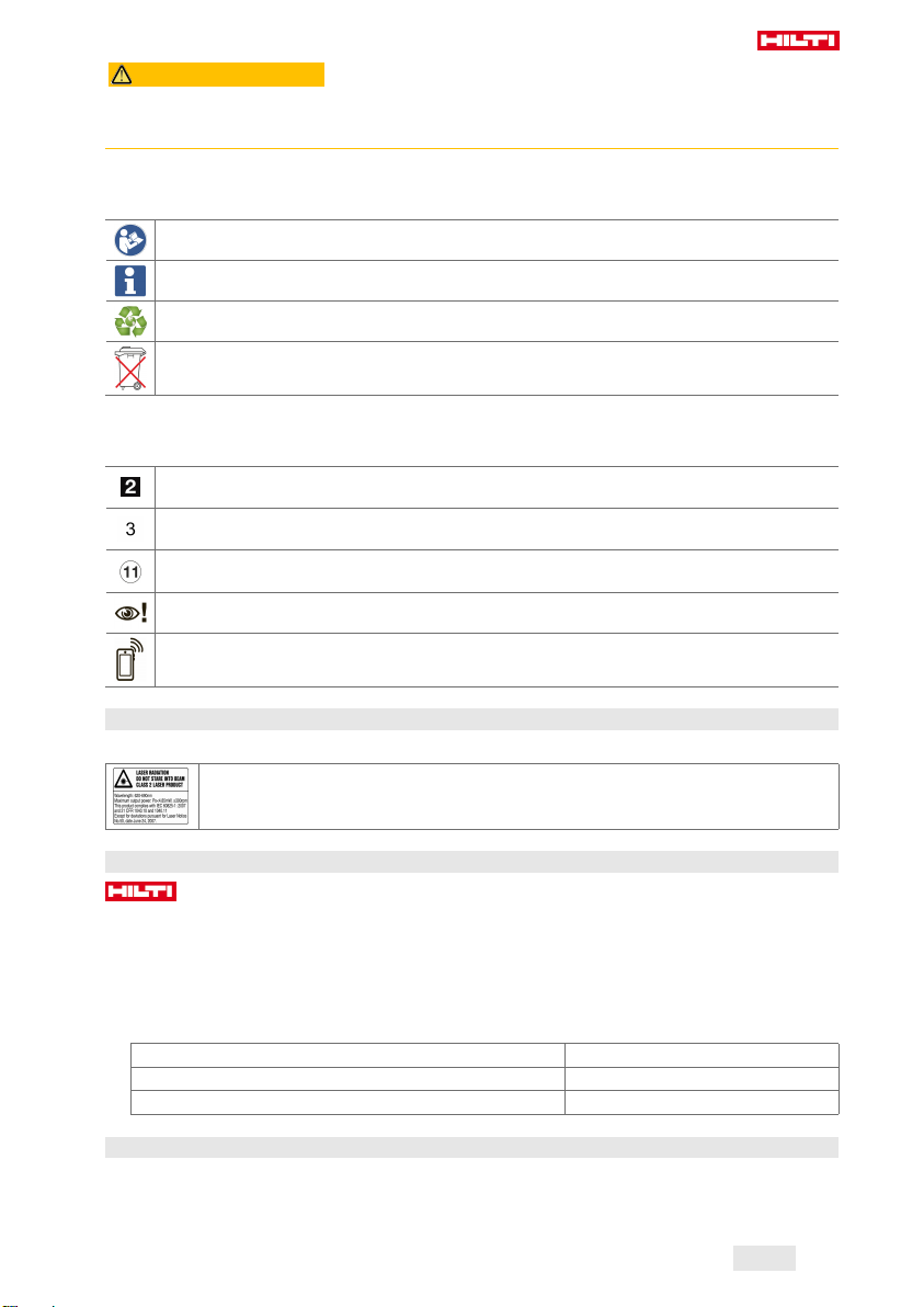
1.2.2 Symbols in the documentation
The following symbols are used in this document:
Read the operating instructions before use.
Instructions for use and other useful information
Dealing with recyclable materials
Do not dispose of electric equipment and batteries as household waste
1.2.3 Symbols in the illustrations
The following symbols are used in illustrations:
These numbers refer to the corresponding illustrations found at the beginning of these operating
instructions
The numbering reflects the sequence of operations shown in the illustrations and may deviate
from the steps described in the text
Item reference numbers are used in the overview illustrations and refer to the numbers used in
the product overview section
This symbol is intended to draw special attention to certain points when handling the product.
Wireless data transfer
1.3 On the product
Laser information
Laser class 2 based on standard IEC60825-1 / EN60825-1:2007 and compliant with CFR
21 § 1040 (Laser Notice 50).
Do not look straight into the laser beam.
1.4 Product information
products are designed for professional users and only trained, authorized personnel are permitted
to operate, service and maintain the products. This personnel must be specifically informed about the
possible hazards. The product and its ancillary equipment can present hazards if used incorrectly by
untrained personnel or if used not in accordance with the intended use.
The type designation and serial number are printed on the rating plate.
▶ Write down the serial number in the table below. You will be required to state the product details when
contacting Hilti Service or your local Hilti organization to inquire about the product.
Product information
Rotating laser | laser receiver PR 30-HVSG A12 | PRA 30G
Generation 02
Serial no.
1.5 Declaration of conformity
We declare, on our sole responsibility, that the product described here complies with the applicable directives
and standards. A copy of the declaration of conformity can be found at the end of this documentation.
The technical documentation is filed here:
English 3
Printed: 07.05.2018 | Doc-Nr: PUB / 5376993 / 000 / 02
Page 6

Hilti Entwicklungsgesellschaft mbH | Tool Certification | Hiltistrasse 6 | D-86916 Kaufering, Germany
1.6 Type approval test
The notified tester, CSA Group Bayern, number 1948, has tested the devices and evaluated the documents
and issued the following type approval certifications:
• PR 30HVSG A12: ZS 17 10 50140 006
• PRA 30G: ZS 17 10 50140 005
2 Safety
2.1 Basic information concerning safety
Read all safety instructions and other instructions. Failure to observe the safety instructions and other
instructions may result in electric shock, fire and/or serious injury.
Retain all safety precautions and instructions for future reference. The term “electric tool” used in the
safety instructions refers to your mains-operated (corded) electric tool or battery-operated (cordless) electric
tool.
2.2 General safety measures
▶ Stay alert, watch what you are doing and use common sense when operating a power tool. Do not
use a power tool while you are tired or under the influence of drugs, alcohol or medication. A moment of
inattention while operating the power tool can result in serious personal injury.
▶ Do not render safety devices ineffective and do not remove information and warning notices.
▶ Keep children well away from laser devices.
▶ Laser radiation in excess of Class 2 may be emitted if the device is opened without following the correct
procedures. Have the device repaired only by Hilti Service.
▶ Project laser beams well above or well below eye height.
▶ Take the influences of the surrounding area into account. Do not use the device where there is a
risk of fire or explosion.
▶ Statement in accordance with FCC §15.21: Changes or modifications not expressly approved by Hilti
can restrict the user’s authorization to operate the equipment.
▶ You must check the accuracy of the device after it has been dropped or subjected to other
mechanical stresses.
▶ When the device is brought into a warm environment from very cold conditions, or vice-versa,
allow it to become acclimatized before use.
▶ When using adapters or accessories, make sure that the equipment is securely mounted.
▶ Keep the laser aperture clean to avoid measurement errors.
▶ The device is designed for the tough conditions of jobsite use, but as with other optical and
electronic instruments (e.g. binoculars, spectacles, cameras) it must be handled with care.
▶ The device is protected to prevent the ingress of moisture, but you must always wipe it dry before
stowing it in the transport container.
▶ Check the device before using it for important measuring work.
▶ Repeatedly check accuracy while using the device.
▶ Make sure that the workplace is well lit.
▶ Do not expose the laser to rain or wet conditions.
▶ Do not touch the contacts.
▶ Maintain the device carefully. Check that moving parts are in full working order and do not jam
and make sure there are no parts that are broken or damaged in such a way as to impair operation
of the device. If it damaged, have the device repaired before use. Many accidents are caused by
poorly maintained equipment.
2.3 Proper preparation of the working area
▶ Secure the area in which you will be taking measurements. Make sure that the laser beam is not
directed toward other persons or toward yourself while setting up the laser tool.
▶ Avoid unfavorable body positions when working from ladders. Make sure you work from a safe
stance and stay in balance at all times.
▶ Readings taken in the vicinity of reflective objects or surfaces, through panes of glass or similar materials
may produce incorrect results.
4 English
Printed: 07.05.2018 | Doc-Nr: PUB / 5376993 / 000 / 02
Page 7

▶ Ensure that the tool is set up on a stable, level surface (not subject to vibration).
▶ Use the tool only within its specified limits.
▶ Use the tool and its accessories etc. in accordance with these instructions and in the manner
intended for the particular type of tool. Take the working conditions and the work to be performed
into account. Use of tools for applications different from those intended could result in a hazardous
situation.
▶ Use of the telescopic staff in the vicinity of overhead high voltage cables is not permissible.
2.4 Electromagnetic compatibility
Although the tool complies with the strict requirements of the applicable directives, Hilti cannot exclude the
following possibilities:
• The tool may be negatively affected by powerful electromagnetic radiation, possibly leading to incorrect
operation.
In these cases, or if you are otherwise unsure, confirmatory measurements should be made by other
means.
• The tool can cause interference to other devices (e.g. aircraft navigation equipment).
2.5 Laser classification for Class 2 laser products
The tool complies with laser Class 2 as per IEC60825-1:2007 / EN60825-1:2007. This tool may be used
without need for further protective measures.
CAUTION
Risk of injury! Do not direct the laser beam toward persons.
▶ Never look directly into the source of the laser beam. In the event of direct eye contact, close your eyes
and move your head out of the path of the laser beam.
2.6 Careful use of battery-powered tools
▶ Do not expose batteries to high temperatures, the direct heat of the sun, and keep them away
from fire. There is a risk of explosion.
▶
Do not disassemble, squash or incinerate batteries and do not subject them to temperatures over
80°C (176°F). This presents a risk of fire, explosion or injury through contact with caustic substances.
▶ Do not subject the battery to hard mechanical impacts and do not throw the battery.
▶ Batteries must be kept out of reach of children.
▶ Avoid ingress of moisture. Ingress of moisture may cause a short circuit, resulting in burning injuries or
fire.
▶ Under abusive conditions, liquid may leak from the battery. Avoid contact with the liquid. If contact
accidentally occurs, flush with water. If the liquid contacts the eyes, also seek medical attention.
Liquid leaking from the battery may cause irritation or burns.
▶ Use only batteries of the type approved for use with the applicable tool. Use of other batteries or
use of the batteries for purposes for which they are not intended presents a risk of fire and explosion.
▶ Store the battery in a cool and dry place. Never store the battery where it is exposed to direct sunlight or
sources of heat, e.g. on heaters / radiators or behind glass.
▶ When not in use, keep the battery and the charger away from paper clips, coins, keys, nails,
screws or other small metal objects that could cause a short circuit at the battery terminals or the
charging contacts. Short-circuiting the contacts on a battery or charger may cause burning injuries or
start a fire.
▶ Do not charge or continue to use damaged batteries (e.g. batteries with cracks, broken parts, bent
or pushed-in and/or pulled-out contacts).
▶ Recharge only with the charger specified by the manufacturer. A charger that is suitable for a certain
type of battery may present a risk of fire when used with other types of battery.
▶ Observe the special guidelines applicable to the transport, storage and use of Li-ion batteries.
▶ The battery must be insulated or removed from the tool before the tool is shipped or sent by mail.
Leaking batteries may damage the tool.
▶ If the battery gets noticeably hot when not in use, this may indicate that the battery or the tool / battery
system is faulty. In this case, place the tool in a non-flammable location, well away from flammable
materials, where it can be kept under observation and allowed to cool down.
Printed: 07.05.2018 | Doc-Nr: PUB / 5376993 / 000 / 02
English 5
Page 8
3 Description
3.1 Product overview
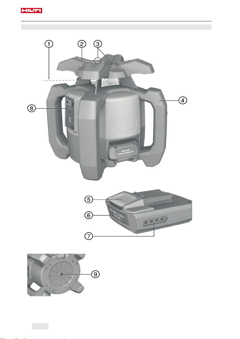
3.1.1 PR 30-HVSG A12 rotating laser
Laser beam (plane of rotation)
@
Rotary head
;
Sight
=
6 English
Printed: 07.05.2018 | Doc-Nr: PUB / 5376993 / 000 / 02
Grip
%
Battery release button
&
Liion battery
(
Page 9
Battery state-of-charge display
)
Control panel
+
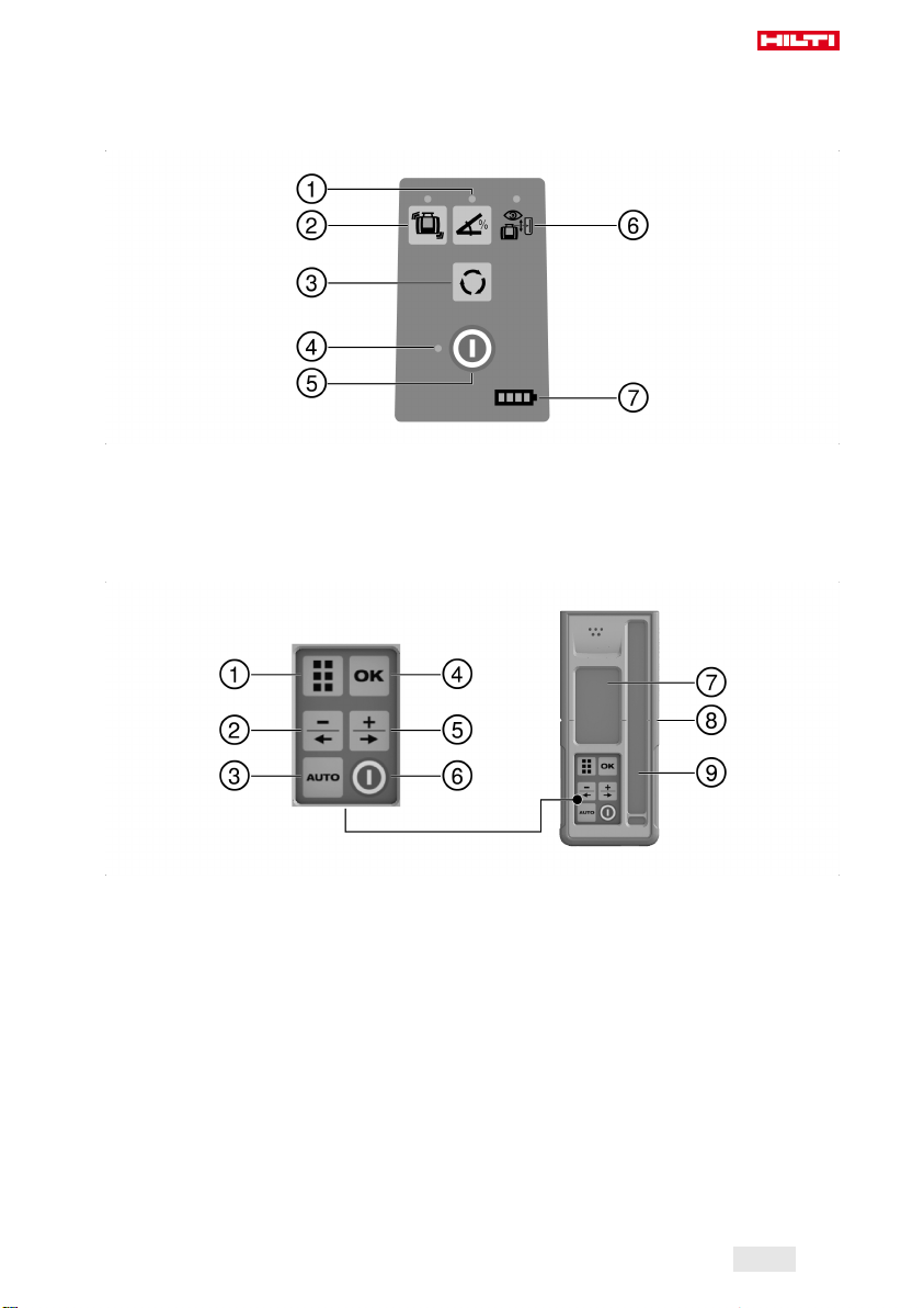
3.1.2 PR 30-HVSG A12 control panel
Base plate with 5/8" thread
§
Inclined plane mode button and LED
@
Shock warning function button and LED
;
Speed of rotation button
=
LED for status “On/off” and “Auto-leveling”
%
3.1.3 PRA 30G laser receiver and control panel
Menu button
@
Decrease inclination, to the left. Move
;
PRA 90 down. Navigation in menu.
Automatic alignment / surveillance mode /
=
marking function
OK button
%
On/off button
&
Surveillance mode LED (only with auto-
(
matic vertical alignment)
Battery charge status LED
)
Increase inclination, to the right. Move
&
PRA 90 up. Navigation in menu.
On/off button
(
Display
)
Marking notch
+
Detection window
§
Printed: 07.05.2018 | Doc-Nr: PUB / 5376993 / 000 / 02
English 7
Page 10
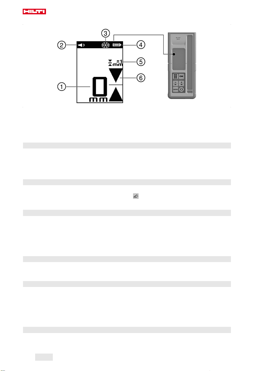
3.1.4 PRA 30G laser receiver display
Distance of the laser beam from the mark-
@
ing notch
Volume indicator
;
Indicator showing beam segments
=
switched off or on
3.2 Intended use
The product described is a rotating laser with a visible rotating laser beam. It can be operated by one person.
The tool is designed to be used to determine, transfer and check levels, verticals, slopes and right angles.
▶ Use only the Hilti B 12⁄2.6 Li-Ion battery for this product.
▶ Use only the Hilti C 4⁄1250 charger for this product.
3.3 Auto-leveling
Auto-leveling takes place after the tool is switched on. LEDs indicate the current operating status. Autoleveling is active and can be deactivated by way of the button. The tool can be set up directly on the
ground or floor, on a tripod, or with the aid of suitable mounting brackets.
3.4 Automatic alignment
Automatic alignment allows a single person to bring the laser plane into alignment with the laser receiver.
The rotating laser tool detects the applicable direction of alignment as follows:
• Horizontal in conjunction with the PRA 90 automatic tripod and PRA 30G laser receiver.
• Inclination in the X-axis in conjunction with the PRA 30G laser receiver.
• Vertical in conjunction with the PRA 30G laser receiver.
3.5 Inclination
Inclination can be carried out manually or automatically. The PRA 79 slope adapter can be used for larger
angles of inclination.
3.6 Surveillance function
The rotating laser monitors alignment of the laser plane in conjunction with the PRA 30G laser receiver. In
the event of an alignment deviation the system corrects the direction of the laser plane, keeping it at the
zero point of the laser receiver. The rotating laser corrects all errors caused by temperature fluctuations,
wind or other such influences. If the optical connection (line of sight) between the rotating laser and the laser
receiver is interrupted for longer than two minutes, the system indicates an error. During vertical alignment,
the surveillance function can be activated only via the AUTO menu.
Battery status indicator
%
Accuracy indicator
&
Position of the receiver relative to the
(
height of the laser plane
3.7 Automatic switch-off
The tool switches off automatically if it is unable to level itself because the rotating laser:
• Is inclined too greatly relative to the horizontal plane (except when in inclined plane mode).
8 English
Printed: 07.05.2018 | Doc-Nr: PUB / 5376993 / 000 / 02
Page 11

• Is blocked mechanically.
• Has been knocked off level by an impact or vibration.
• Has identified a fault.
When the tool has switched itself off, rotation stops and all LEDs flash.
3.8 Shock warning function
If the rotating laser is knocked off level during operation, the built-in shock warning function switches the
tool to warning mode. The shock warning function does not go active until two minutes after completion of
auto-leveling. If a button on the control panel is pressed within this two-minute period it will take a further
two minutes for the shock warning function to go active. If the rotating laser is in warning mode:
• All LEDs flash.
• The laser stops rotating.
• The laser beam switches off.
The sensitivity of the shock warning function can be set using the PRA 30G laser receiver.
The shock warning function can be switched off by pressing the button if the ground or floor is not free
from vibration or when you are working in inclined plane mode.
▶ Deactivate the shock warning function. → page 19
3.9 Sleep mode
Sleep mode may be activated on the rotating laser during breaks between work or during other activities. All
settings concerning the laser plane or inclination are retained while in this status. Sleep mode saves power
and extends battery life.
PRA 30G the laser receiver is used to activate / deactivate sleep mode.
Sleep mode remains active for a maximum of 4 hours. The system switches itself off after this time.
3.10 Switching off beam segments
Individual segments of the path of the laser beam can be deactivated in order to:
• Avoid exposing yourself or bystanders to the laser beam.
• Avoid influencing other measuring or alignment work being carried out in the vicinity.
3.11 Laser receiver / remote control unit
Hilti laser receivers digitally indicate the distance between the marking notch on the laser receiver and the
position at which the laser beam (laser plane) strikes the detection area on the receiver. The laser beam can
also be received over long distances. The PRA 30G can be used as a laser receiver and also as a remote
control unit for the rotating laser.
3.12 Pairing accessories and device
Pairing accessories and device
Pairing is the act of enabling accessories and devices to communicate with each other by wireless.
The rotating laser and the laser receiver are already paired when supplied. This helps ensure trouble-free
operation within the vicinity of other wireless devices.
Additional laser receivers or PRA 90 automatic tripods cannot be used without first being paired.
▶ Pair the rotating laser and the laser receiver. → page 19
▶ Pair the tripod and laser receiver. → page 19
3.13 LED indicators
The rotating laser is equipped with LED indicators.
Status Meaning
All LEDs blink. • The tool has been bumped, knocked off level or
has a fault.
The auto-leveling LED flashes green. • The tool is in the leveling phase.
English 9
Printed: 07.05.2018 | Doc-Nr: PUB / 5376993 / 000 / 02
Page 12

Status Meaning
The auto-leveling LED shows steady green. • The tool has leveled itself / is operating normally.
The shock warning LED shows steady orange. • Shock warning mode is deactivated.
The inclination LED shows steady orange • Inclined plane mode is active.
The surveillance LED flashes orange. • The tool is aligning the laser plane with the
(PRA 30G) reference point.
The surveillance mode LED shows steady orange. • The tool is in surveillance mode. Alignment with
the reference point (PRA 30G) is correct.
3.14 Li-ion battery charge state display
The Li-ion battery features a state of charge display.
Status Meaning
4 LEDs light. • Charge status: 75 % to 100 %
3 LEDs light. • Charge status: 50 % to 75 %
2 LEDs light. • Charge status: 25 % to 50 %
1 LED lights. • Charge status: 10 % to 25 %
1 LED blinks. • Charge status: < 10 %
When the tool is in operation, the battery charge status is indicated in the display on the tool.
When not in operation, battery charge state can be indicated by lightly pressing the release button.
During charging, charge state is indicated by the LEDs on the battery (please refer to the operating
instructions for the charger).
3.15 Items supplied
PR 30-HVSG A12 rotating laser, PRA 30G laser receiver / remote control unit, 2 batteries (AA cells), PRA 54
target plate, operating instructions.
Other system products approved for use with this product can be found at your local Hilti Store or online at:
www.hilti.group.
4 Technical data
4.1 Technical data, rotating laser
Receiving range (diameter) PRA 30G
Communication range (PRA 30G)
Accuracy at 10 m (under standard ambient conditions in accordance with MILSTD810G)
Laser class
Self-leveling range
Operating temperature
Storage temperature
Weight (including battery)
Drop test height (under standard ambient conditions in accordance with MILSTD810G)
Protection class in accordance with IEC 60529 (except battery
and battery compartment)
Plumb beam
Maximum emitted transmission power
Frequency
10 English
Printed: 07.05.2018 | Doc-Nr: PUB / 5376993 / 000 / 02
PR 30-HVSG A12
2 m …300 m
200 m
±1.0 mm
2, visible
±5°
−10 ℃ …50 ℃
−25 ℃ …60 ℃
2.5 kg
1.5 m
IP66
Constant beam, perpendicular
to the plane of rotation
7.3 dBm
2,400 MHz …2,483.5 MHz
Page 13

4.2 Technical data, laser receiver
Indicator range, distance from zero
Laser plane indication accuracy
Length of the detection area
Center indication from top edge of casing
Time without detection before automatic power off
Range of remote control unit (diameter) for the PR 30HVSG A12
Drop test height in the PRA 83 laser receiver holder (under stan-
±52 mm
±0.5 mm
≤ 120 mm
75 mm
15 min
2 m …150 m
2 m
dard ambient conditions in accordance with MILSTD810G)
Operating temperature
Storage temperature
Weight (including batteries)
Protection class in accordance with IEC 60529 (except battery
−20 ℃ …50 ℃
−25 ℃ …60 ℃
0.25 kg
IP66
compartment)
Maximum emitted transmission power
Frequency
−0.2 dBm
2,400 MHz …2,483.5 MHz
5 Operating the rotating laser
5.1 Preparations at the workplace
Observe the safety instructions and warnings in this documentation and on the product.
5.2 Handling the rotating laser and battery correctly
The B12 battery has no protection class. Do not expose the battery to rain or wet conditions.
In accordance with the Hilti instructions, the battery may be used only with the associated product
and must be inserted in the battery compartment for this purpose.
1. Fig. 1: Working in horizontal mode.
2. Fig. 2: In inclined plane mode, the rotating laser should be lifted at the control panel side.
3. Fig. 3: Laying down or transporting in an inclined position. Working in the vertical plane.
◁ Hold the rotating laser so that the battery compartment does NOT face upwards, so that no moisture
can enter.
English 11
Printed: 07.05.2018 | Doc-Nr: PUB / 5376993 / 000 / 02
Page 14

5.3 Inserting / removing the battery
CAUTION
Electrical hazard. Dirty contacts may cause a short circuit.
▶ Check that the contacts on the battery and on the tool are free from foreign objects before inserting the
battery.
CAUTION
Risk of injury. If the battery is not fitted correctly it may drop out and fall.
▶ Check that the battery is securely seated in the tool so that it cannot drop out and fall, thereby presenting
a hazard to other persons.
1. Push the battery in until it engages securely.
◁ The rotating laser is ready to be switched on.
2. Press the release button and hold it in this position.
3. Pull the battery out.
5.4 Switching the rotating laser on and working in the horizontal plane
Check the accuracy of the rotating laser before using it for important tasks, especially if it has been
dropped or subjected to unusual influences or impacts, or after long periods of storage.
1. Mount the rotating laser on a suitable holder or bracket.
2.
Press the button.
◁ The auto-leveling LED flashes green.
12 English
Printed: 07.05.2018 | Doc-Nr: PUB / 5376993 / 000 / 02
Page 15

◁ As soon as the tool has leveled itself, the laser beam switches on and begins to rotate and the "auto
leveling" LED shows steadily.
A wall bracket or tripod may be used as mounting devices. The angle of inclination of the surface
on which it stands should not exceed ± 5°.
5.5 Manual horizontal alignment using the PRA 90 tripod
The rotating laser is mounted on the PRA 90 automatic tripod.
The PRA 30G laser receiver, the rotating laser and the PRA 90 automatic tripod are paired.
The PRA 30G laser receiver and the control panel of the PRA 90 automatic tripod are facing each
other and in direct line of sight.
1.
Press the button on the rotating laser, on the PRA 30G laser receiver and on the PRA 90 automatic
tripod.
◁ The devices are ready for use.
2.
To shift the laser plane up, press the button on the PRA 30G laser receiver or the “up” arrow button
on the PRA 90 automatic tripod.
3.
To shift the laser plane down, press the button on the PRA 30G laser receiver or the “down” arrow
button on the PRA 90 automatic tripod.
5.6 Automatic horizontal alignment using the PRA 90 tripod
The rotating laser is mounted on the PRA 90 automatic tripod.
The PRA 30G laser receiver, the rotating laser and the PRA 90 automatic tripod are paired.
The PRA 30G laser receiver and the control panel of the PRA 90 automatic tripod are facing each
other and in direct line of sight.
Printed: 07.05.2018 | Doc-Nr: PUB / 5376993 / 000 / 02
English 13
Page 16

1.
Press the button on the rotating laser, on the PRA 30G laser receiver and on the PRA 90 automatic
tripod.
◁ The devices are ready for use.
2. Keep the marking notch on the PRA 30G laser receiver at the height that is to be set. The PRA 30G laser
receiver should be held steady or secured in place.
3.
Begin automatic alignment by double-clicking the button on the PRA 30G laser receiver or select the
corresponding function in the AUTO menu.
◁ The PRA 90 automatic tripod moves up and down until the correct position is reached. An signal tone
is emitted by the laser receiver repeatedly during this procedure.
◁ The rotating laser levels itself once the position has been reached. Successful completion is indicated
by a continuous signal tone with a duration of 5 seconds. The symbol is displayed briefly.
▽
If automatic alignment cannot be completed successfully, short signal tones are emitted and the
is displayed briefly.
4. Check the height setting in the display.
5. Remove the PRA 30G laser receiver.
6.
Stop automatic alignment before completion by double-clicking the button on the PRA 30G laser
receiver.
5.7 Manual vertical alignment
The rotating laser is placed or securely mounted in the vertical position (tripod, wall mount, facade or
batter board adapter, or lying on the rear grips). A reference point (A) is marked below the laser head
(e.g. a nail on a batter board or a spot of paint on the floor or ground).
The PRA 30G laser receiver and the rotating laser are paired.
The PRA 30G laser receiver and the receiving side of the rotating laser are facing each other and in
direct line of sight. The best receiving side of the rotating laser is the side at which the battery is inserted.
14 English
Printed: 07.05.2018 | Doc-Nr: PUB / 5376993 / 000 / 02
Page 17

1.
Press the button on the rotating laser.
◁ The rotating laser levels itself and then projects a stationary downward-pointing laser beam.
2. Position the rotating laser so that the projected laser beam strikes reference point (A) exactly. Please
note: The reference point is not a plumb point!
3.
To shift the laser plane to the right or left, press the or button on the PRA 30G laser receiver.
◁ The rotating laser begins rotating after pressing one of the two direction arrow buttons.
5.8 Automatic vertical alignment
The rotating laser is placed or securely mounted in the vertical position (tripod, wall mount, facade or
batter board adapter, or lying on the rear grips). A reference point (A) is marked below the laser head
(e.g. a nail on a batter board or a spot of paint on the floor or ground).
The PRA 30G laser receiver and the rotating laser are paired.
The PRA 30G laser receiver and the receiving side of the rotating laser are facing each other and in
direct line of sight. The best receiving side of the rotating laser is the side at which the battery is inserted.
1.
Press the button on the rotating laser.
◁ The rotating laser levels itself and then projects a stationary downward-pointing laser beam.
2. Position the rotating laser so that the projected laser beam strikes reference point (A) exactly. Please
note: The reference point is not a plumb point!
3. Keep the marking notch on the PRA 30G laser receiver on the plane that is to be set. The PRA 30G laser
receiver should be held steady or secured in place.
4.
Begin automatic alignment by double-clicking the button on the PRA 30G laser receiver or select the
corresponding function in the AUTO menu.
◁ The head of the rotating laser pivots to the left and right until the position is reached. An signal tone
is emitted by the laser receiver repeatedly during this procedure.
Printed: 07.05.2018 | Doc-Nr: PUB / 5376993 / 000 / 02
English 15
Page 18

◁
The rotating laser levels itself once the position has been reached. The symbol is displayed
briefly.
▽
If automatic alignment cannot be completed successfully, short signal tones are emitted and the
is displayed briefly.
5.
Double-click the button on the PRA 30G laser receiver.
◁ During automatic alignment: Stops automatic alignment before completion.
5.9 Automatic vertical alignment with surveillance function
The rotating laser is placed or securely mounted in the vertical position (tripod, wall mount, facade or
batter board adapter, or lying on the rear grips). A reference point (A) is marked below the laser head
(e.g. a nail on a batter board or a spot of paint on the floor or ground).
The PRA 30G laser receiver and the rotating laser are paired.
The PRA 30G laser receiver and the receiving side of the rotating laser are facing each other and in
direct line of sight. The best receiving side of the rotating laser is the side at which the battery is inserted.
1.
Press the button on the rotating laser.
◁ The rotating laser levels itself and then projects a stationary downward-pointing laser beam.
2. Position the rotating laser so that the projected laser beam strikes reference point (A) exactly. Please
note: The reference point is not a plumb point!
3. Keep the marking notch on the PRA 30G laser receiver on the plane that is to be set. The PRA 30G laser
receiver should be held steady or secured in place.
4.
Press the button on the PRA 30G to display the AUTO menu. Start automatic alignment with
surveillance function .
◁ The head of the rotating laser pivots to the left and right until the position is reached. An signal tone
is emitted by the laser receiver repeatedly during this procedure.
◁
The rotating laser levels itself once the position has been reached. The symbol is displayed
briefly and the signal tone stops.
◁ The rotating laser switches to the surveillance function. Small deviations due to external influences
are then compensated automatically and the laser beam is kept at the height of the marking notch on
the laser receiver.
▽
If automatic alignment cannot be completed successfully, short signal tones are emitted and the
is displayed briefly.
5. Do NOT remove the PRA 30G laser receiver from the target plane so long as surveillance mode is active.
6.
Double-click the button on the PRA 30G laser receiver.
◁ During automatic alignment: Stops automatic alignment before completion.
◁ If the surveillance function is active: Deactivate (end) the surveillance function.
5.10 Setting the inclination manually
The rotating laser, depending on the application, is mounted or positioned securely.
The PRA 30G laser receiver and the rotating laser are paired.
The PRA 30G laser receiver and the receiving side of the rotating laser are facing each other and in
direct line of sight. The best receiving side of the rotating laser is the side at which the battery is inserted.
16 English
Printed: 07.05.2018 | Doc-Nr: PUB / 5376993 / 000 / 02
Page 19

1. Position the rotating laser either at the upper edge or lower edge of the inclined plane.
2. Use the target sight on the head of the tool to align the rotating laser parallel to the inclined plane.
3.
Press the button on the rotating laser and the PRA 30G laser receiver.
◁ The laser switches on, the beam begins to rotate and the “auto leveling” LED lights as soon as the
tool has leveled itself.
4.
Press the button on the rotating laser.
◁ The inclined plane mode LED on the rotating laser lights constantly.
◁ The inclined plane mode symbol is shown on the PRA 30G laser receiver.
5.
Use the or buttons on the laser receiver to incline the laser plane.
When the angle of inclination is set manually, the rotating laser levels the laser plane once and then
fixes it. Vibration, changes in temperature or other influences that may occur during the course of
the day may affect the position of the laser plane.
5.11 Setting the inclination using the PRA 79 slope adapter
Depending on the application, the PRA 79 slope adapter can be mounted on a tripod or on a wall
bracket.
The angle of inclination of the PRA 79 slope adapter is set to 0°.
1. Mount the rotating laser on the PRA 79 slope adapter. Observe the operating instructions for the PRA 79
slope adapter. The control panel of the rotating laser should be facing you.
2. Position the rotating laser either at the upper edge or lower edge of the inclined plane.
3.
Press the button on the rotating laser.
◁ The laser switches on, the beam begins to rotate and the “auto leveling” LED lights as soon as the
tool has leveled itself.
4.
Press the button on the rotating laser.
◁ The inclined plane mode LED on the rotating laser lights constantly.
5. Set the PRA 79 slope adapter to the desired angle of inclination.
When the angle of inclination is set manually, the rotating laser levels the laser plane once and then
fixes it. Vibration, changes in temperature or other influences that may occur during the course of
the day may affect the position of the laser plane.
5.12 Setting inclination automatically
The rotating laser, depending on the application, is mounted or positioned securely.
The PRA 30G laser receiver and the rotating laser are paired.
The PRA 30G laser receiver and the receiving side of the rotating laser are facing each other and in
direct line of sight. The best receiving side of the rotating laser is the side at which the battery is inserted.
Printed: 07.05.2018 | Doc-Nr: PUB / 5376993 / 000 / 02
English 17
Page 20

1. Position the rotating laser either at the upper edge or lower edge of the inclined plane.
2.
Press the button on the rotating laser and the PRA 30G laser receiver.
◁ The laser switches on, the beam begins to rotate and the “auto leveling” LED lights as soon as the
tool has leveled itself.
3.
Press the button on the rotating laser.
◁ The inclined plane mode LED on the rotating laser lights constantly.
◁ The inclined plane mode symbol is shown on the PRA 30G laser receiver.
4. Position the marking notch on the PRA 30G laser receiver at the other edge of the inclined plane.
5.
Begin automatic alignment by double-clicking the button on the PRA 30G laser receiver or select the
corresponding function in the AUTO menu.
◁ The rotating laser inclines the laser plane on the X-axis automatically until the mark at the PRA 30G
laser receiver is reached. An signal tone is emitted by the laser receiver repeatedly during this
procedure.
◁ The rotating laser levels itself on the Y-axis once the position has been reached. Successful
completion is indicated by a continuous signal tone with a duration of 5 seconds. The
symbol is displayed briefly.
▽
If automatic alignment cannot be completed successfully, short signal tones are emitted and the
is displayed briefly.
6.
Stop automatic inclination before completion by double-clicking the button on the PRA 30G laser
receiver.
If the rotating laser begins the automatic search in the wrong direction, press the button to
change the search direction.
5.13 Manual scan line function
1.
Press the button on the rotating laser.
2. Adjust the laser plane to the desired position / height. The scan line function can be used in horizontal,
vertical and inclined plane mode.
3.
Press the button on the PRA 30G to display the menu.
4.
Select the manual scan line function .
5. The width of the scan line can be set to one of four widths via the scan line width submenu.
6.
After selecting the scan line function in the menu, the and symbols can be used to shift the laser
line to the left or right. The laser receiver does not require to be within the path of laser beam in order to
do this.
5.14 Automatic scan line function
1.
Press the button on the rotating laser.
2. Adjust the laser plane to the desired position / height. The scan line function can be used in horizontal,
vertical and inclined plane mode.
3.
Press the button on the PRA 30G to display the AUTO menu.
4.
Start the automatic scan line function .
18 English
Printed: 07.05.2018 | Doc-Nr: PUB / 5376993 / 000 / 02
Page 21

5. Bring the laser receiver into the desired position. The rotating laser automatically concentrates the beam
along a shortened line in the area of the laser receiver.
The width of the scan line can be adjusted using menu on the PRA 30G. The narrower the scan
line is set, the brighter it will appear.
6.
After selecting the scan line function in the menu, the and symbols can be used to shift the laser
line to the left or right. The laser receiver does not require to be within the path of laser beam in order to
do this.
5.15 Deactivating the shock warning function
1.
Press the button on the rotating laser.
2.
Press the button.
◁ The shock warning deactivation LED lights constantly, indicating that the function has been
deactivated.
To return to standard operating mode, switch the rotating laser off and then switch it back on again.
6 Operating the laser receiver
6.1 Inserting the batteries in the laser receiver
▶ Insert the batteries in the laser receiver.
Use only batteries that have been manufactured in accordance with international standards.
6.2 Pairing the rotating laser and the PRA 30G laser receiver
1.
Position both tools at a distance of about 0.5 m from each other. Press the button on both devices
for at least 3 seconds.
◁ Successful pairing is confirmed by all LEDs blinking on the rotating laser and a signal tone is emitted
by the PRA 30G laser receiver. The and symbols are displayed briefly on the laser
receiver.
◁ The devices are paired.
◁ The rotating laser and the laser receiver switch themselves off.
2. Switch the devices on again.
6.3 Pairing the PRA 90 tripod and the PRA 30G laser receiver
1.
Position both tools at a distance of about 0.5 m from each other. Press the button on both devices
for at least 3 seconds.
◁ Successful pairing is confirmed by all LEDs blinking on the PRA 90 automatic tripod and by a signal
tone emitted by the PRA 30G laser receiver. The and symbols are displayed briefly on
the laser receiver.
English 19
Printed: 07.05.2018 | Doc-Nr: PUB / 5376993 / 000 / 02
Page 22

◁ The devices are paired.
◁ The automatic tripod and the laser receiver switch themselves off.
2. Switch the devices on again.
◁ The rotating laser and the automatic tripod are shown in the display on the laser receiver.
6.4 Using the laser receiver to detect the laser beam
1.
Press the button on the laser receiver.
2. Hold the laser receiver with the receiving window directly in the plane of the laser beam.
3. Hold the laser receiver still while alignment is taking place and take care to ensure that the line of sight
between the laser receiver and the rotating laser is not obstructed.
◁ Detection of the laser beam is indicated by visual and audible signals.
◁ The laser receiver indicates the distance to the roting laser.
◁ The laser receiver can be used at distances (radiuses) of up to 300 m.
6.5 Explanation of the menu options
•
To display the menu, press the button.
•
Use the and buttons to navigate in the menu.
•
The symbol selected is shown on a dark background. Example:
•
An active setting is shown in a black frame. Example:
•
Press the button to confirm your selection.
Main menu
Marking function
Speed of rotation
Rotating laser settings
Laser receiver settings
Information
Back. Takes you back to a higher level in the menu or leaves the menu without making any
changes.
Marking function menu
Line width settings menu (display shows the currently set width)
Move line to the left
Move line to the right
Line width settings menu
Wide
Medium
Narrow
Point
Speed of rotation menu
300 revolutions per minute
20 English
Printed: 07.05.2018 | Doc-Nr: PUB / 5376993 / 000 / 02
Page 23

600 revolutions per minute
1200 revolutions per minute
Rotating laser settings menu
Sleep mode
Shock warning
Switch off beam segments
Shock warning submenu
Level 1, high sensitivity
Level 2, medium sensitivity
Level 3, low sensitivity
Sleep mode submenu
Sleep mode on
Sleep mode off
Submenu for switching off beam segments
Example The upper left beam segment is active
Example The upper left beam segment is not active
The other beam segments can be activated and deactivated in the same way.
Laser receiver settings menu
Volume level
Accuracy
Volume level submenu
Audible signal off
Volume level 1
Volume level 2
Volume level 3
Accuracy submenu
1 mm
2 mm
5 mm
10 mm
Printed: 07.05.2018 | Doc-Nr: PUB / 5376993 / 000 / 02
English 21
Page 24

25 mm
Menu information
Software versions
Service deadline
QR code
AUTO menu
Press the button once to open the AUTO menu.
Automatic alignment
Automatic alignment with surveillance function
Automatic scan line function
6.6 PRA 83 laser receiver with holder
1. Fit the laser receiver into the rubber sleeve of the PRA 83 at an angle from above.
2. Then press the laser receiver into the rubber sleeve until the sleeve surrounds the laser receiver
completely.
3. Fit the rubber sleeve onto the magnetic grip piece.
4.
Press the button.
5. Unscrew the clamping knob on the grip piece slightly.
6. Mount the PRA 83 laser receiver on a telescopic staff or leveling staff and secure it by tightening the
clamping knob.
◁ The laser receiver is ready for taking measurements.
22 English
Printed: 07.05.2018 | Doc-Nr: PUB / 5376993 / 000 / 02
Page 25

6.7 PRA 80 laser receiver with holder
1. Open the retainer on the PRA 80 and insert the laser receiver.
2. Close the retainer on the PRA 80.
3.
Press the button.
4. Unscrew the clamping knob on the grip piece slightly.
5. Mount the PRA 80 laser receiver on a telescopic staff or leveling staff and secure it by tightening the
clamping knob.
◁ The laser receiver is ready for taking measurements.
Printed: 07.05.2018 | Doc-Nr: PUB / 5376993 / 000 / 02
English 23
Page 26

6.8 PRA 81 laser receiver with holder
1. Open the retainer on the PRA 81 and insert the laser receiver.
2. Close the retainer on the PRA 81.
3.
Press the button.
4. Hold the laser receiver with the receiving window directly in the plane of the laser beam.
5.
Position the laser receiver so that the distance display shows “0”.
6. Use the measuring tape to measure the desired offset distance.
7 Care and maintenance
7.1 Care and maintenance
WARNING
Risk of injury with battery inserted !
▶ Always remove the battery before carrying out care and maintenance tasks!
Care and maintenance of the tool
• Carefully remove stubborn dirt from the tool.
• Use only a slightly damp cloth to clean the casing. Do not use cleaning agents containing silicone as
these may attack the plastic parts.
Care of the Liion batteries
• Keep the battery free from oil and grease.
• Use only a slightly damp cloth to clean the casing. Do not use cleaning agents containing silicone as
these may attack the plastic parts.
• Avoid ingress of moisture.
Maintenance
• Check all visible parts and controls for signs of damage at regular intervals and make sure that they all
function correctly.
24 English
Printed: 07.05.2018 | Doc-Nr: PUB / 5376993 / 000 / 02
Page 27

• Do not operate the cordless tool if signs of damage are found or if parts malfunction. Have the tool
repaired by Hilti Service immediately.
• After cleaning and maintenance, fit all guards or protective devices and check that they function correctly.
Cleaning the laser exit window
▶ Blow dust off the laser exit window.
▶ Do not touch the laser exit window with your fingers.
Coarse cleaning materials can scratch the glass, impairing the accuracy of the device. Use only
pure alcohol or water for cleaning, as other liquids can attack the plastic parts.
Observe the temperature limits when drying the equipment.
7.2 Hilti Measuring Systems Service
Hilti Measuring Systems Service checks the product and, if deviations from the specified accuracy are found,
recalibrates it and checks it again to ensure conformity with specifications. The service certificate provides
written confirmation of conformity with specifications at the time of the test. The following is recommended:
• A suitable test interval should be chosen in accordance with the degree of use.
• Have the product checked by Hilti Measuring Systems Service after exceptionally heavy use or subjection
to unusual conditions or stress, before important work or at least once a year.
Having the product checked by Hilti Measuring Systems Service does not relieve the user of his/her
obligation to check the product before and during use.
7.3 Checking accuracy
In order to ensure compliance with the technical specifications, the tool should be checked regularly (at least
before each major / relevant measuring task).
After falling from considerable height, the tool should be checked for correct, accurate operation. When the
following conditions are fulfilled it can be assumed that the tool is operating faultlessly:
• The height of the fall did not exceed the height given in the technical data.
• The tool operated faultlessly before the impact.
• The tool suffered no obvious mechanical damage from the impact (e.g. breakage of the pentaprism).
• The tool projects a rotating laser beam when in operation.
Printed: 07.05.2018 | Doc-Nr: PUB / 5376993 / 000 / 02
English 25
Page 28

7.4 Checking the main and transverse horizontal axes
1. Set up the tripod approx. 20 m from a wall and level the tripod head with a spirit level.
2. Mount the tool on the tripod and use the visual sighting method (front and rear sights) to aim the tool at
the wall.
3. Fig. a: Use the receiver to catch the laser beam and mark a point (point 1) on the wall.
4. Pivot the tool clockwise through 90° about its own axis. In doing so, ensure that the height of the tool
does not change.
5. Fig. b: Use the laser receiver to catch the laser beam and mark a second point (point 2) on the wall.
6. Fig. c and d: Repeat the two previous steps twice and use the laser receiver to catch the beam and mark
points 3 and 4 on the wall.
When this procedure is carried out carefully, the vertical distance between the two marked points
1 and 3 (main axis) or, respectively, points 2 and 4 (transverse axis) should be less than 2 mm (at
20 m). If the deviation is greater than this, please return the tool to Hilti Service for calibration.
26 English
Printed: 07.05.2018 | Doc-Nr: PUB / 5376993 / 000 / 02
Page 29

7.5 Checking the vertical axis
1. Place the device in the vertical position on a floor that is as flat as possible, approx. 1 to 10 m from a
wall.
2. Align the grips parallel with the wall.
3. Switch on the device and mark the reference point (R) on the floor.
4. With the aid of the receiver, mark point (A) at the base of the wall.
5. With the aid of the receiver, mark point (B) at a height of approx. 10 m.
6. Pivot the device through 180° and realign it with the reference point (R) on the floor and with point (A) at
the base of the wall. This can also be done using the automatic alignment function.
7. Bring the vertical laser plane into alignment automatically. → page 15
8. With the aid of the receiver, mark point (C) at a height of approx. 10 m.
◁ When this procedure is carried out carefully, the horizontal distance between the two marked points
(B) and (C) should be < 2 mm (at 10 m). If the deviation is greater than this, return the device to Hilti
Service for calibration.
8 Transport and storage
8.1 Transport and storage of cordless tools
Transport
CAUTION
Accidental starting during transport !
▶ Always transport your products with the batteries removed!
▶ Remove the battery.
▶ Transport the tool and batteries individually packaged.
▶ Never transport batteries in bulk form (loose, unprotected).
▶ Check the tool and batteries for damage before use after long periods of transport.
Storage
CAUTION
Accidental damage caused by defective or leaking batteries !
▶ Always store your products with the batteries removed!
▶ Store the tool and batteries in a place that is as cool and dry as possible.
▶ Never store batteries in direct sunlight, on heating units or behind a window pane.
▶ Store the tool and batteries in a place where they cannot be accessed by children or unauthorized
persons.
▶ Check the tool and batteries for damage before use after long periods of storage.
9 Troubleshooting
If the trouble you are experiencing is not listed in this table or you are unable to remedy the problem by
yourself, please contact Hilti Service.
English 27
Printed: 07.05.2018 | Doc-Nr: PUB / 5376993 / 000 / 02
Page 30

Trouble or fault Possible cause Action to be taken
The tool doesn’t work. The battery is not fully inserted. ▶ Push the battery in until it
engages with an audible click.
Low battery. ▶ Change the battery and charge
the empty battery.
The tool has a fault or error. ▶ Switch the tool off and then on
again. Contact Hilti Service if
the fault / error persists.
The battery runs down more
quickly than usual.
The battery doesn’t engage
with an audible click.
The tool or battery gets very
hot.
Very low ambient temperature. ▶ Warm up the battery slowly to
room temperature.
The retaining lugs on the battery
are dirty.
▶ Clean the retaining lugs and refit
the battery.
Electrical fault. ▶ Switch the tool off immediately,
remove the battery, keep it
under observation, allow it to
cool down and contact Hilti
Service.
Serious error. This message is always accompanied by the corresponding symbol.
▶ Further operation is not possi-
ble. Switch off all tools / devices
and then switch them on again.
Serious error. All the LEDs on
the rotating laser flash.
The warning message is always
accompanied by the correspond-
▶ Solutions are indicated by the
corresponding symbol.
ing symbol.
Warning
Pairing the rotating laser and laser
receiver is not possible.
▶ Follow the instructions on
pairing the devices exactly.
Pairing was unsuccessful.
Pairing was unsuccessful.
Shock warning.
Laser position warning.
28 English
Printed: 07.05.2018 | Doc-Nr: PUB / 5376993 / 000 / 02
▶ Pair the rotating laser and the
laser receiver. → page 19
Pairing the tripod and laser receiver is not possible.
▶ Follow the instructions on
pairing the devices exactly.
▶ Pair the tripod and laser
receiver. → page 19
Shock warning has been triggered. ▶ Make sure the rotating laser is
standing securely and is not
exposed to vibration.
▶ Adjust the shock warning
sensitivity setting.
▶
Deactivate the shock warning
function. → page 19
The laser is too steeply inclined,
leveling not possible.
▶ Bring the laser into an upright
position as far as possible.
▶ Switch the rotating laser on.
→ page 12
Page 31

Trouble or fault Possible cause Action to be taken
The laser receiver is outside the
automatic inclination range.
▶ Set the inclination of the laser
plane using the PRA 79 slope
adapter. → page 17
Inclination warning.
The surveillance function is not
possible or is interrupted.
▶ Check the positions of the
rotating laser and laser receiver
and reposition if necessary.
▶ Remove obstacles from the
path of the laser beam (laser
Surveillance mode warning.
plane).
▶ Then restart the surveillance
function.
▶ Use automatic alignment
with the surveillance function. → page 16
Automatic height adjustment is not
possible.
▶ The tripod is not paired. Pair the
tripod, rotating laser and laser
receiver.
▶ Switch on the tripod.
▶ Switch on the rotating laser.
Height adjustment warning.
Low battery in the rotating laser. ▶ Charge the battery.
Low battery in the rotating
laser.
Low battery in the laser receiver. ▶ Charge the battery.
Low battery in the laser receiver.
Low battery in the tripod. ▶
Charge the battery.
Low battery in the tripod.
The tool is in sleep mode. ▶ Activate / deactivate sleep
mode.
Sleep mode is active.
10 RoHS (Restriction of Hazardous Substances)
Click on the link to go to the table of hazardous substances: qr.hilti.com/r7677226.
There is a link to the RoHS table, in the form of a QR code, at the end of this document.
Printed: 07.05.2018 | Doc-Nr: PUB / 5376993 / 000 / 02
English 29
Page 32

11 Disposal
Most of the materials from which Hilti tools and appliances are manufactured can be recycled. The
materials must be correctly separated before they can be recycled. In many countries, your old tools,
machines or appliances can be returned to Hilti for recycling. Ask Hilti Service or your Hilti representative
for further information.
Battery disposal
Improper disposal of batteries can result in health hazards from leaking gases or fluids.
▶ DO NOT send batteries through the mail!
▶ Cover the terminals with a non-conductive material (such as electrical tape) to prevent short circuiting.
▶ Dispose of your battery out of the reach of children.
▶ Dispose of the battery at your Hilti Store, or consult your local governmental garbage disposal or public
health and safety resources for disposal instructions.
▶ Do not dispose of power tools, electronic equipment or batteries as household waste!
12 Manufacturer’s warranty
▶ Please contact your local Hilti representative if you have questions about the warranty conditions.
30 English
Printed: 07.05.2018 | Doc-Nr: PUB / 5376993 / 000 / 02
Page 33

Printed: 07.05.2018 | Doc-Nr: PUB / 5376993 / 000 / 02
Page 34

Printed: 07.05.2018 | Doc-Nr: PUB / 5376993 / 000 / 02
Page 35

Printed: 07.05.2018 | Doc-Nr: PUB / 5376993 / 000 / 02
Page 36

Hilti = registered trademark of Hilti Corp., Schaan 20180503
Printed: 07.05.2018 | Doc-Nr: PUB / 5376993 / 000 / 02
 Loading...