

Page 1

PP 10/11
*233821*
233821
Hilti Corporation
LI-9494 Schaan
Tel.: +423/234 2111
Fax: +423 /234 29 65
www.hilti.com
Hilti = registered trademark of Hilti Corp., Schaan W 3117 0106 00-Pos. 2 1 Printed in Liechtenstein © 2006
Right of technical and programme changes reserved S. E. & O.
233821 / A
Operating instructions en
Bruksanvisning sv
Brugsanvisning da
10 11
12
00_Cover_PP_10_11_P2.qxd 23.1.2006 09:14 Seite 1
Page 2

1 2 3
4 5
6 7
8 9
00_Cover_PP_10_11_P2.qxd 23.1.2006 09:14 Seite 5
Page 3

PP 10 / 11 pipe laser
It is essential that the operating instructions
are read before the tool is operated for the
first time.
Always keep these operating instructions
together with the tool.
Ensure that the operating instructions are
with the tool when it is given to other
persons.
Contents Page
1 General information 1
2 Description 2
3 Accessories 3
4 Technical data 3
5 Safety rules 4
6Beforeuse 5
7Operation 7
8 Care and maintenance 10
9 Troubleshooting 11
10 Disposal 11
11 Warranty 12
12 FCC statement (applicable in US) / IC
statement (applicable in Canada) 12
13 EC declaration of conformity 13
Component parts 1
PP 10/11 pipe laser
Remote control signal receiving window
@
Warning / standby LED
;
Control panel
=
Display
%
Grip
&
Grip mount
(
PPA 84 cable connector
)
Battery compartment cover lock
+
PPA 82 battery incl. mains adaptor
§
Plumb spot
/
PP10/11pipelaser
Laser exit window
:
Remote control signal receiving window
·
Plumb spot
$
Pivot point mark
£
Control panel
Direction control button / auto centering
|
Plumb spot ON button
¡
Laser beam mode button
Q
Remote control signal receiving window
W
Lock button
E
Target plate auto-centering button (only with the
R
PP 11)
Direction control button / auto centering
T
SET button
Z
Laser beam up / down, value-entry button
U
Warning / standby LED
I
Laser beam up / down, value-entry button
O
ON / OFF button
P
en
1. General information
1.1 Safety notices and their meaning
DANGER
Draws attention to imminent danger that could lead
to serious bodily injury or fatality.
CAUTION
Draws attention to a potentially dangerous situation
that could lead to slight personal injury or damage to
the equipment or other property.
NOTE
Draws attention to instructions and other useful information.
1
Page 4

1.2 Explanation of the pictograms and other
information
Warning signs
Laser warning plates for the USA in accordance with
CFR21§1040(FDA)
On the tool
en
General
warning
Symbols
Read the
operating
instructions
before use.
On the tool
DANGER
LASER RADIATION - AVOID DIRECT
675-695nm < 5mW max.
CLASS IIIa LASER PRODUCT
Do not stare into the beam.
Laser warning plates for the USA in accordance with
CFR 21 § 1040 (FDA):
On the tool
DANGER
LASER RADIATION - AVOID DIRECT
520-550nm < 5mW max.
CLASS IIIa LASER PRODUCT
Do not stare into the beam.
EYE EXPOSURE
EYE EXPOSURE
Return waste
material for
recycling.
3R
Laser warning plate in accordance with IEC825 /
EN60825-1:2003
1 These numbers refer to the corresponding illustrations. The illustrations can be found on the fold-out
cover pages. Keep these pages open while studying
the operating instructions.
In these operating instructions, the designation “the
tool” always refers to the PR 10 / 11 pipe laser.
Location of identification data on the tool
The type designation and serial number can be found
onthetypeplateonthetool.Makeanoteofthisdata
in your operating instructions and always refer to it
when making an enquiry to your Hilti representative
or service department.
Type :
Serial no.:
2. Description
2.1 Use of the product as directed
The tool is designed to be used for determining, transferring or checking alignment in the horizontal and
inclined planes, e.g.: Transferring height marks or setting up inclinations. Hilti supplies various accessories
which allow the tool to be used with maximum efficiency.
2.2PP10/11pipelaser
The PP 10 /11 is a pipe laser featuring a visible laser
(spot) that can be used for alignment in the horizontal
or inclined planes.
2
2.3 Features
A single person working with the tool can set out any
desired inclination (within the -15% to +40% range)
with great accuracy. The tool levels itself automatically
when set up within 10% of the horizontal plane.
2.4 Automatic cut-out
The laser beam and the LED on the control panel blink
if the tool is set up outside its self-leveling range. The
direction in which the tool requires to be tilted is also
shown in the display.
Page 5

2.5 PPA 82 battery
Battery performance drops at low temperatures.
2.6 Automatic charging cut-out
The charging operation is stopped automatically to
protect the battery when the temperature exceeds the
specified charging temperature range.
NOTE
Charge the battery every 3 to 4 months. Store the
battery at a maximum temperature of 30°C (86°F).
Allowing the battery to become fully discharged may
have a negative effect on its future performance.
Charging may take less than 9 hours if the battery
was not previously fully discharged.
2.7 Use of various power sources
Three different power sources may be used: the
standard PPA 82 battery supplied or the PPA 83
battery holder or PPA 84 external 12V cable which
are available as accessories.
2.8 Items supplied
1 PP 10 or 11 pipe laser (depending on version
purchased)
1 PPA 20 remote control unit
1Targetplate,short
1 Target plate, long
1 Target plate holder
1 PPA 81 charging adaptor
1 PPA 82 battery incl. mains adaptor
1 Set of 4 screw feet, 150 mm
1 Set of 4 screw feet, 200 mm
1 Set of 4 screw feet, 250 mm
1 Set of 4 screw feet, 300 mm
1 Centering screw
1 PP 10 / 11 operating instructions
1 PPA 20 operating instructions
4 Batteries (size AAA cells)
1 Manufacturer’s certificate
1 Hilti toolbox
3. Accessories
PP 10 / 11 accessories
PPA 83 battery holder (size D cells) PPA 83 (size D cells)
PPA 84 connecting cable (12V) PPA 84 (12V)
Vertical and horizontal adaptors
PPA73tripodadaptor PPA73
PPA 40 telescopic sight PPA 40
en
4. Technical data
NOTE
Right of technical changes reserved.
Wavelength, PP 10 633 mm
Wavelength, PP 11 532 mm
Accuracy (at 24 °C) ±0.5 mm @ 10 m horizontal
Laser class Class IIIa, visible, < 5 mW (IEC825-1 / EN60825-
1:2003; FDA 21 CFR 1040)
Laser beam diameter 12 mm
Self-leveling range ±10°
Inclinationrange -15to40%
Min. inclination setting 0.001 %
PP10batterylifeat20°C[+68°F] Alkaline:70h;NiMH:>48h
PP11batterylifeat20°C[+68°F] Alkaline:45h;NiMH:>32h
3
Page 6

Operating temperature range -20 to 50 °C
Storage temperature range -30 to 60 °C
Wateranddustresistant Yes(submersiontoadepthofupto5m/24h)
Weight Including 4 batteries 3.8 kg
Dimensions Without grip
en
Dimensions With grip
Automatic target plate detection (only PP 11)
Range 5 to 150 m
330mmx122mmdia.
330 mm x 122 mm dia.
5. Safety rules
5.1 Basic information concerning safety
a) In addition to the information relevant to safety
given in each of the sections of these operating
instructions, the following points must be strictly
observed at all times.
5.2 Misuse
a) The tool and its ancillary equipment may present
hazards when used incorrectly by untrained personnel or when used not as directed.
b) To avoid the risk of injury, use only genuine Hilti
accessories and additional equipment.
c) Modification of the tool is not permissible.
d) Observe the information printed in the operating
instructions concerning operation, care and main-
tenance.
e) Do not render safety devices ineffective and do not
remove information and warning notices.
f) Keep laser tools out of reach of children.
g) Failure to follow the correct procedures when
opening the tool may cause emission of laser
radiation in excess of class 3. Have the tool repaired
only at a Hilti service center.
h) Take the influences of the surrounding area into
account.Donotusethetoolwherethereisarisk
of fire or explosion.
i) (Statement in accordance with FCC §15.21):
Changes or modifications not expressly approved
by Hilti could limit the user’s right to operate the
equipment.
5.3 Proper organization of the work area
a) Secure the area in which you are working and take
care to avoid directing the beam towards other
persons or towards yourself when setting up the
tool.
b) Avoid unfavorable body positions when working
on ladders or scaffolding. Make sure you work
from a safe stance and stay in balance at all times.
c) Measurements taken through panes of glass or
other objects may be inaccurate.
d) Ensure that the tool is set up on a steady, level
surface (not subject to vibration).
e) Use the tool only within its specified limits.
f) Check that your PP 10 / 11 is responding only to
your PPA 20 and not to other PA 350s that may be
in use on the jobsite.
5.3.1 Electromagnetic compatibility
a) Although the tool complies with the strict re-
quirements of the relevant directives, Hilti cannot
entirely rule out the possibility that the tool may
cause interference to other equipment (e.g. aircraft
navigation equipment) or that the tool may be sub-
ject to interference caused by powerful radiation,
possibly leading to incorrect operation. Check the
accuracy of the tool by taking measurements by
other means when working under such conditions
or if you are unsure.
5.3.2 Laser classification for tools of the classes
3A and 3R
a) Depending on the version purchased, the tool
conforms to laser class 3 in accordance with CFR
21 § 1040 (FDA). Do not stare into the beam and
do not direct the beam toward other persons.
b) Laser Class 3A tools may be operated only by
appropriately trained persons.
4
Page 7

c) Theareainwhichthetoolisinusemustbemarked
with laser warning signs.
d) The plane of the laser beam should be well above
or well below eye height.
e) Precautions must be taken to ensure that the
laser beam does not unintentionally strike highly
reflective surfaces.
f) Precautions must be taken to ensure that persons
do not stare directly into the beam.
g) The laser beam must not be allowed to project
beyond the controlled area.
h) When not in use, laser tools should be stored in
an area to which unauthorized persons have no
access.
5.4 General safety rules
a) Check the condition of the tool before use. If the
tool is found to be damaged, have it repaired at a
Hilti service center.
b) The accuracy of the tool must be checked after it
has been dropped or subjected to other mechanical
stresses.
c) When the tool is brought into a warm environment
from very cold conditions, or vice-versa, allow i t
to become acclimatized before use.
d) If mounting on an adaptor, ensure that the tool is
screwed on securely.
e) Keep the laser exit aperture clean to avoid meas-
urement errors.
f) Although the tool is designed for the tough condi-
tions of jobsite use, as with other optical and electronic instruments (e.g. binoculars, spectacles,
cameras) it should be treated with care.
g) Although the tool is protected to prevent entry of
dampness, it should be wiped dry each time before
being put away in its transport container.
h) Check the tool before using it for important meas-
uring work.
i) Check the accuracy of the measurements several
timesduringuseofthetool.
5.4.1 Electrical
a) Keep the batteries out of reach of children.
b) The batteries may explode or release toxic sub-
stances. Do not allow the batteries to overheat and
do not expose them to fire.
c) Do not charge the batteries.
d) Do not solder the batteries into the tool.
e) Do not discharge the batteries by short circuiting
as this may cause them to overheat and swell up.
f) Do not attempt to open the batteries and do not
subject them to excessive mechanical stress.
en
6. Before use
NOTE
The tool may be powered only by the PPA 82 battery
or by batteries manufactured in accordance with IEC
285.
6.1 Switching the tool on
Press the ON / OFF button.
NOTE
The PP 10 / 11 is capable of leveling itself within a
range of +/- 10%.The tool levels itself automatically
when set up within this range. The LED begins to
blink when the inclination of the tool is more than +/10% from the set inclination. The tool should then be
tilted in the direction indicated by the arrow.
6.2 Battery warning indicator 2
1 Battery power is adequate
2 Battery power is low, the laser
maycontinuetobeused.
NOTE
When this status is reached, the
laser transmits a battery warning
signal to the laser receiver.
3 The battery is discharged.
NOTE
Recharge the NiMH battery or
insert new alkaline batteries.
4 The display blinks
NOTE
The laser tool is charged using
the PPA 84 12V connecting
cable.
5
Page 8

6.3 Removing the PPA 83 battery holder or PPA 82
battery
1. Turnthebatterylockingknobto“OPEN”and
remove the battery holder.
2. Turn the knob on the battery compartment cover
en
to the “OPEN” position.
6.4 Replace the batteries.
1. Replace the used batteries in the battery holder
with new ones.
6.5 Fitting the PPA 83 battery holder or PPA 82
battery
1. Refit the battery holder after replacing the batteries.
NOTE The PPA 83 can be inserted into the tool
only in one position.
2. Turn the knob to the “LOCK” position.
6.6 Connecting the PPA 84 cable
NOTE
If using a battery that is fitted to a motor vehicle,
please first switch off the engine.
NOTE
Take care to ensure correct polarity when connecting
both terminals.
NOTE
Switch the tool off before connecting or disconnecting
the external power cable.
The connecting cable is designed for connecting to a
12 V battery.
1. Connect the red clip to the positive (+) pole.
2. Connect the black clip to the negative (-) pole.
6.7 Charging the PPA 82 battery
When charging the battery, the ambient temperature
should be between + 10ºC and + 40ºC.
Exceedingthespecifiedchargingtimemayshorten
the life of the battery. The battery is charged automatically when the laser is operated at a temperature
of [+10ºC to +40ºC] with an external battery.
1. Fit the PPA 81 charging adapter to the PPA 82
battery.
2. Connect the power supply unit to the charging
adapter.
3. Plug the power supply unit into a power outlet.
4. Check that the correct voltage has been set on the
power supply unit.
The charging control lamp lights green when the
charging operation is complete.
6.8 Charging status
Charging
status
Red LED lights
Charging
Green LED lights
Charging completed
Blinks green
Error during charging
Blinks red
The protective cut-out has been
activated. The PP 10 / 11 may be
used while in this status.
6
Page 9

7. Operation
7.1 Button functions 3
1. Switching
on the plumb
spot
2. Laser beam
mode
3. Lock This button locks all data entry
4. Target plate
auto-centering
button (only
PP 11)
5. Direction
control
5. Parameter
selection
5. Automatic
centering
6. Laser beam
up and down
6. Value entry Positive or negative values may
7. SET button This button is used to confirm
8. ON / OFF
button
The plumb spot can be switched
on or off by pressing the laser
beam mode button (switches
itself off automatically after 30
minutes).
The laser beam can be switched
over by pressing the laser beam
mode button. PP 10: constant
beam or blinking beam PP 11:
constant beam, blinking beam,
high-power mode
functions. Values can then no
longer be changed. The data
entry functions can be unlocked
by pressing the LOCK button
again.
The laser beam finds the center
of the target plate automatically.
Moves the laser beam to the left
or right.
Used to select the parameters to
be set.
The laser beam centers itself
automatically when both direction control buttons are pressed
at the same time.
Moves the laser beam up or
down.
be entered. When both buttons
are pressed at the same time,
inclination is set automatically to
00.000% .
the selected parameters.
Thisbuttonisusedtoswitchthe
tool on or off.
7.2 Symbols in the display 4
1 Plumb spot indicator.
2 Direction indicator (shows the
direction of the laser beam).
3 Battery status indicator (shows
the remaining battery capacity in
3stages).
4 Self-leveling indicator (blinks
while the laser is leveling itself,
the display then changes to the
laser mode set).
5 Inclination indicator
6 Percentage
7 Lock indicator (the data entered
cannot be changed)
8 Electronic bubble level
9 Laser mode display
7.3 Warnings 5
1. Battery
warning indicator
2. Level warning indicator
3. Lateral inclination warning indicator
7.4 Switching the tool on
Press the ON / OFF button.
NOTE
The PP 10 / 11 is capable of leveling itself within a
range of +/- 10%.The tool levels itself automatically
when set up within this range. The LED begins to
blink when the inclination of the tool is more than +/-
Operation is no longer possible.
Replace / recharge the battery
or connect an external power
source.
The laser is tilted beyond its
self-leveling range. T ilt the laser
tool in the direction of the arrow
shown in the display.
The laser has been rotated
beyond its self-leveling range.
Rotate the laser tool in the
direction of the arrow shown in
the display.
en
7
Page 10

10% from the set inclination. The tool should then be
tilted in the direction indicated by the arrow.
7.5 Setting the inclination 7
Inclination can be set either manually or automatically.
en
Inclination can be set within the -15% to +40% range
(for inclination of over 10%, the adaptor or some
other aid should be used to provide initial inclination
of the laser tool).
7.5.1 Automatic entry of inclination 7
1. Switch the tool on by pressing the ON / OFF
button.
2. Press the SET button. The set value is displayed
andthe±indicatorblinks.
3. Press the laser beam UP or DOWN button to
change the sign.
4. Press the right-hand direction control button in
order to reach the correct position (the left direction control button can be used to move back).
5. Press the laser beam UP or DOWN button to
change the value.
6. Press the right-hand direction control button to
move to the next position.
7. Press the laser beam UP or DOWN button to
change the value. Repeat the steps described
above to change other numerical values.
8. Press the SET button when the value entered is
correct.
The laser beam then begins to move to the specified setting.
7.5.2 Manual entry of inclination
NOTE
Inclination can also be set directly by moving the laser
beam. Check that the locking function has not been
activated.
The value indicated becomes higher or lower as the
laser beam is moved.
1. Press the laser beam UP or DOWN button. The
laser beam then moves up or down.
2. Press the laser beam UP and DOWN buttons at
the same time to move the laser beam to the zero
position.
The laser beam moves immediately to the 0.000%
position.
7.7 Beam position indicator 6
1 Beam position indicator
2 End position left
3 End position right
7.8 Adjusting the position of the beam 6
The maximum lateral adjustment range is 9m at a
distance of 30m. The speed of movement can be
varied.
If the button is pressed briefly, the laser beam moves
slowly.
If the button is pressed for longer, the laser beam
moves quickly.
The current position of the beam can be read from
the display at any time.
7.8.1 Adjusting the beam end position left / right
The display informs the operator when the beam has
reached the left or right end position and cannot
be moved further. The display blinks to i nform the
operator of this status.
If this position is reached frequently it is recommended that the tool is pivoted slightly to the left or right
and the beam then realigned.
7.9 Automatic centering
Press both direction control buttons (left and right) at
the same time to center the laser beam automatically.
7.10 Target plate auto-centering (only PP 11) 8
NOTE
This feature is particularly useful for setting up the
laser tool the next working day.
1. Set up the target plate with the reflective stripes
facing the laser tool.
2. Press the target plate auto-centering button. The
laser then finds the horizontal center of the target
plate automatically.
7.6 Aligning the target line 6
Use the direction control buttons on the PP 10 / 11 or
PPA 20 remote control unit to move the laser beam
horizontally to the right or left.
8
Page 11

7.11 Display while searching
1 The tool has not yet completed
the self-leveling procedure.
NOTE
This procedure will first be
completed.
2 The display indicatesstabilization
of the laser beam after selfleveling.
3 Searching (auto centering) then
begins.
NOTE
The display indicates that
searching (auto centering) is in
progress.
4 Automatic alignment has been
completed.
NOTE
Check the position of the laser
spot on the target plate. If
necessary, the remote control or
the direction control buttons (left
/ right) can be used to readjust
the position of the beam.
5 If the beam loses contact with
the target plate while searching,
theproceduremustberestarted.
7.12 Selecting the laser beam mode
Press the laser beam mode button as often as necessary until the desired display mode is shown in the
display.
7.13 Operating modes
1 Constant beam
2 Blinking beam
3 High-power mode (only with the
PP 11)
7.14 Adjusting the electronic bubble level 9
When the tool is pivoted, the electronic bubble level
appears clearly in the display.
Adjust the tool until the “bubble” is in the center of
the display.
The LED begins to blink as soon as the tool’s selfleveling range is exceeded.
7.15 Fitting the screw feet and centering screw
Fit the appropriate screw feet for the pipe diameter
before setting up the laser in the pipe.
NOTE
Screw feet of the following sizes are supplied: 150
mm, 200 mm, 250 mm and 300 mm.
7.16 Setting the target plate size
Setthetargetplatesizetoavaluesuitableforthepipe
diameter you are working with.
7.17 Target plate, front (1)
1 Locking screw
2Targetplate,small
3 Bubble level
4 Target plate holder
7.18 Target plate, rear (2)
2 Reflective stripes (only for the
PP 11)
7.19 Setting parameters
7.19.1 Setting units of measurement to % or ‰
1. Press the ON / OFF button and the LOCK button
at the same time.
The set values are shown in the display.
2. Use the laser beam UP / DOWN button to move
to the “unit” line.
3. Press the SET button to enter the correct mode.
4. Select the value you wish to change by pressing
the direction control button.
5. Press the SET button to confirm the entry.
The tool then returns to the normal operating
mode.
7.19.2 Setting and activating the security code
Unauthorized persons can be prevented from using
the laser tool by entering a 4-digit security code.
Please note that once the security code has been
activated, the laser tool can no longer be operated
without entering this code. The code will be requested
automatically after the tool is switched on.
en
9
Page 12

1. Press the ON / OFF button and the LOCK button
at the same time.
The set values are shown in the display.
2. Use the laser beam UP/DOWNbuttontomove
en
to the “input S code” line.
3. Press the SET button to enter the correct mode.
4. The laser beam UP / DOWN button and direction
control button can be used to navigate to the
corresponding number. Press the SET button
to confirm the number selected. Press the SET
button to confirm the code as soon as the four
desired digits are displayed in the “code” area of
the display.
5. The display then returns to the previous mode.
The security code can then be activated (“on”
by pressing the SET button) or deactivated later
(“off” by pressing the SET button again).
The tool then returns to the normal operating
mode.
7.19.3 Entering the name of the company
These instructions describe how to enter or change
the name of the company. A maximum of 32 characters (16 characters in 2 rows) can be entered.
1. Press the ON / OFF button and the LOCK button
at the same time.
The set values are shown in the display.
2. Use the laser beam UP / DOWN button to move
to the “change name” line.
3. Press the SET button to enter the correct mode.
4. Use the laser beam UP / DOWN button and
direction control button to navigate to the corresponding characters / digits. Press the SET button
to confirm the character selected. Press the SET
button to confirm the entry as soon as the correct
name / designation is displayed.
The tool then returns to the normal operating
mode.
7.20 Checking the tool’s accuracy
1. Set the laser to an inclination of 0.000%.
2. Set up a leveling staff at a distance of 1m and a
second leveling staff at a distance of 60m. Note
the heights at which the laser beam strikes the
staffs.
3. Set up an optical level in the middle between the
twolevelingstaffsandreadtheheightsfromboth
staffs.
4. Calculate the difference between the readings
from the optical level and the laser at staffs 1
and 2. If the two values are identical, the laser is
correctly adjusted.
NOTE If the differences X1 and X2 are not equal,
please contact your nearest Hilti representative.
8. Care and maintenance
8.1 Cleaning and drying
1. Blow dust off the lenses.
2. Do not touch the glass with your fingers.
3. Use only a clean, soft cloth for cleaning. If necessary, moisten the cloth slightly with pure alcohol
oralittlewater.
NOTE Do not use any other liquids as these may
damage the plastic components.
4. Observe the temperature limits when storing your
equipment. This is particularly important in winter
/ summer if the equipment is kept inside a motor
vehicle (-30°C to + 60°C).
8.2 Storage
Remove the tool from its case if it has become wet.
The tool, its carrying case and accessories should be
cleaned and dried (at maximum 40°C / F). Repack the
equipment only once it is completely dry.
10
Check the accuracy of the equipment before it is used
after a long period of storage or transportation.
Remove the batteries from the tool before storing it
for a long peri od.
8.3 Transport
Use the Hilti toolbox or packaging of equivalent quality
for transporting or shipping your equipment.
CAUTION
Always remove the batteries before shipping the tool.
8.4 Hilti calibration service
We recommend that the tool is checked by the Hilti
calibration service at regular intervals in order to
verify its reliability in accordance with standards and
legal requirements.
Page 13

Use can be made of the Hilti calibration service
at any time, but checking at least once a year is
recommended.
The calibration service provides confirmation that the
tool is in conformance, on the day it is tested, with
the specifications given in the operating instructions.
The tool will be readjusted if deviations from the
manufacturer’s specification are found. After check-
ing and adjustment, a calibration sticker applied to
the tool and a calibration certificate provide written
verification that the tool operates in accordance with
the manufacturer’s specification.
Calibration certificates are always required by companies certified according to ISO 9 00x.
Your local Hilti Center or representative will be pleased
to provide further information.
9. Troubleshooting
Fault Possible cause Remedy
E02/03 An internal measurement problem has
occurred.
E99 An internal memory problem has oc-
curred.
ERROR The tool was moved while in standby
mode.
Switch the tool off and then on again. An
error message may be displayed if the
tool is knocked or shaken. In this case,
eliminate the cause of the disturbance.
Switchthetooloffandthenonagain.
Switch the tool off and then on again and
check that it is set up correctly.
NOTE
Contact your nearest Hilti Service Center
if the fault persists.
10. Disposal
CAUTION
Improper disposal of the equipment may h ave serious consequences: The burning of plastic components
generates toxic fumes which may present a health hazard. Batteries may explode if damaged or exposed to
very high temperatures, causing poisoning, burns, acid burns or environmental pollution. Careless disposal
may permit unauthorized and improper use of the equipment. This may result in serious personal injury, injury
to third parties and pollution of the environment.
en
Most of the materials from which Hilti tools or machines are manufactured can be recycled. The materials must
be correctly separated before they can be recycled. In many countries, Hilti has already made arrangements
for taking back your old tools for recycling. Please ask your Hilti customer service department or Hilti
representative for further information.
For EC countries only
Disposal of electric tools together with household waste is not permissible!
In observance of European Directive 2002/96/EC on waste electrical and electronic equipment
and its implementation in accordance with national law, electric tools that have reached the end
of their life must be collected separately and returned to an environmentally compatible recycling
facility.
11
Page 14

Dispose of the batteries in accordance with national regulations.
en
11. Warranty
Hilti warrants that the product supplied is free from
defects in material and workmanship. This warranty
is valid as long as the product is operated and
handled correctly, cleaned and serviced properly and
in accordance with the Hilti operating instructions,
all warranty claims are made within 12 months (unless other mandatory national regulations prescribe
a longer minimum period) from the date of sale (invoice date) and the technical system is maintained,
i.e. only genuine Hilti consumables, accessories and
spare parts are used with the product.
This warranty provides the free-of-charge repair or
replacement of defective parts only. Parts requiring
repair or replacement as a result of normal wear and
tear are not covered by this warranty.
Additional claims are excluded, unless mandatory national regulations prohibit such exclusion. In
particular, Hilti is not obligated for direct, indirect,
incidental or consequential damages, losses or expenses in connection with,orbyreasonof,theuse
of, or inability to use the product for any purpose.
Implied warranties of merchantability or fitness for
a particular purpose are specifically excluded.
Send the product and/or related parts immediately
upon discovery of a defect to the local Hilti marketing
organization for repair or replacement.
This constitutes Hilti’s entire obligation with regard
to warranty and supersedes all prior or contemporaneous comments and oral or written agreements
concerning warranties.
12. FCC statement (applicable in US) / IC statement (applicable in Canada)
CAUTION
This equipment has been tested and found to comply
with the limits for a Class B digital device, pursuant
to part 15 of the FCC rules. These limits are designed
to provide reasonable protection against harmful interference in a residential installation. This equipment
generates, uses and may radiate radio frequency
energy. Accordingly, if not installed and used in accordance with the instructions, it may cause harmful
interference to radio communications.
However, there is no guarantee that interference will
not occur in a particular installation. If this equipment
does cause harmful interference to radio or television
reception, which can be determined by turning the
equipment off and on, the user is encouraged to try
tocorrecttheinterferencebytakingthefollowing
measures:
Reorient or relocate the receiving antenna.
Increase the separation between the equipment and
receiver.
Connect the equipment to a power outlet on a circuit
different from that to which the receiver is connected.
Consult your dealer or an experienced TV/radio technician for assistance.
NOTE
Changes or modifications not expressly approved
by Hilti could limit the user’s right to operate the
equipment.
This device complies with part 15 of the FCC Rules
and RSS-210 of the IC.
Operation is subject to the following two conditions:
(1) This device may not cause harmful interference.
(2) This device must accept any interference received,
including interference that may cause undesired operation.
12
Page 15
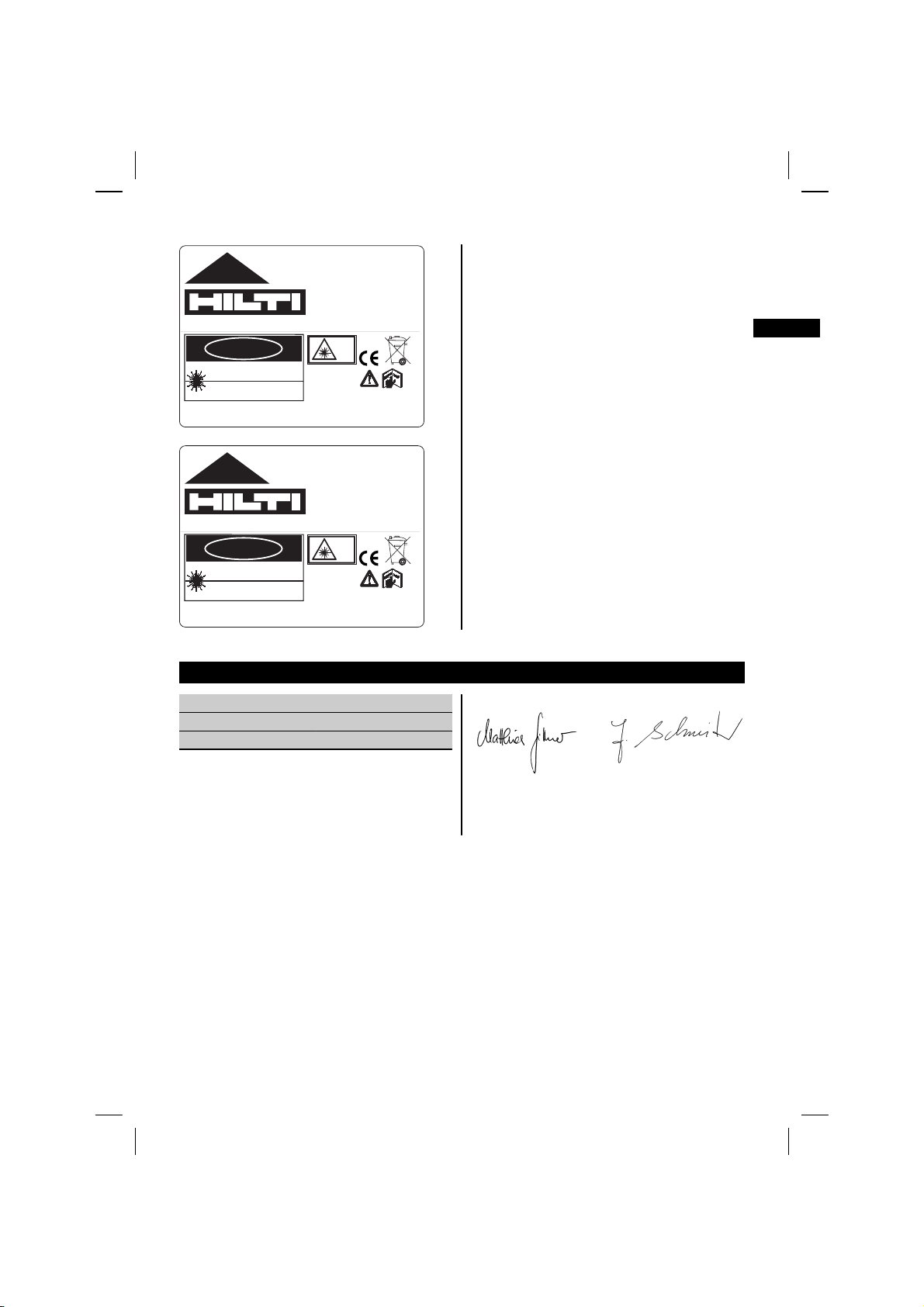
AVOID EXPOSURE
LASER LIGHT IS EMITTED
FROM THIS APERTURE
PP 10
Made in Japan
Hilti= registered trademark of the Hilti Corporation, Schaan, Liechtenstein
DANGER
LASER RADIATION - AVOID DIRECT
620-690nm < 5mW max.
CLASS IIIa LASER PRODUCT
Item No.: 319781
Date .:
EYE EXPOSURE
AVOID EXPOSURE
LASER LIGHT IS EMITTED
FROM THIS APERTURE
3R
EN 60825-1:2003
This Laser Product
complies with 21CFR
1040 as applicable
Power: 6.0V=nom./250 mA
319789
PP 11
Made in Japan
Hilti= registered trademark of the Hilti Corporation, Schaan, Liechtenstein
DANGER
LASER RADIATION - AVOID DIRECT
520-550nm < 5mW max.
CLASS IIIa LASER PRODUCT
Item No.: 319791
Date .:
EYE EXPOSURE
3R
EN 60825-1:2003
This Laser Product
complies with 21CFR
1040 as applicable
Power: 6.0V=nom./250 mA
319795
13. EC declaration of conformity
Designation: Pipe laser
Type: PP 10 / 11
Year of design: 2005
We declare, on our sole responsibility, that this
product complies with the following directives and
standards: EN 61000-6-2, EN 61000-6-3.
Hilti Corporation
Matthias Gillner Dr. Heinz-Joachim Schneider
Head BU Measuring Systems Executive Vice President
BU Measuring Systems Business Area Electric
07 2005 07 2005
Tools & Accessoires
en
13
 Loading...