

Hilti POS 15, POS 18 Operating Instructions Manual

POS 15/18
Operating instructions en
Mode d’emploi fr
Manual de instrucciones es
Manual de instruções pt
Printed: 07.07.2013 | Doc-Nr: PUB / 5135739 / 000 / 00

1
2
Printed: 07.07.2013 | Doc-Nr: PUB / 5135739 / 000 / 00
43
5
6
Printed: 07.07.2013 | Doc-Nr: PUB / 5135739 / 000 / 00

7 8
9
Printed: 07.07.2013 | Doc-Nr: PUB / 5135739 / 000 / 00

HPO
p
p
p
HPO
10
Printed: 07.07.2013 | Doc-Nr: PUB / 5135739 / 000 / 00

ORIGINAL OPERATING INSTRUCTIONS
POS 15/18 total station
It is essential that the operating instructions
are read before the tool is operated for the
first time.
Always keep these operating instructions together with the tool.
Ensure that the operating instructions are
with the tool when it is given to other persons.
1 These numbers refer to the corresponding illustrations. The illustrations can be found on the fold-out cover
pages. Keep these pages open while studying the operating instructions.
In these operating instructions, the designation “the tool”
always refers to the POS 15 or POS 18.
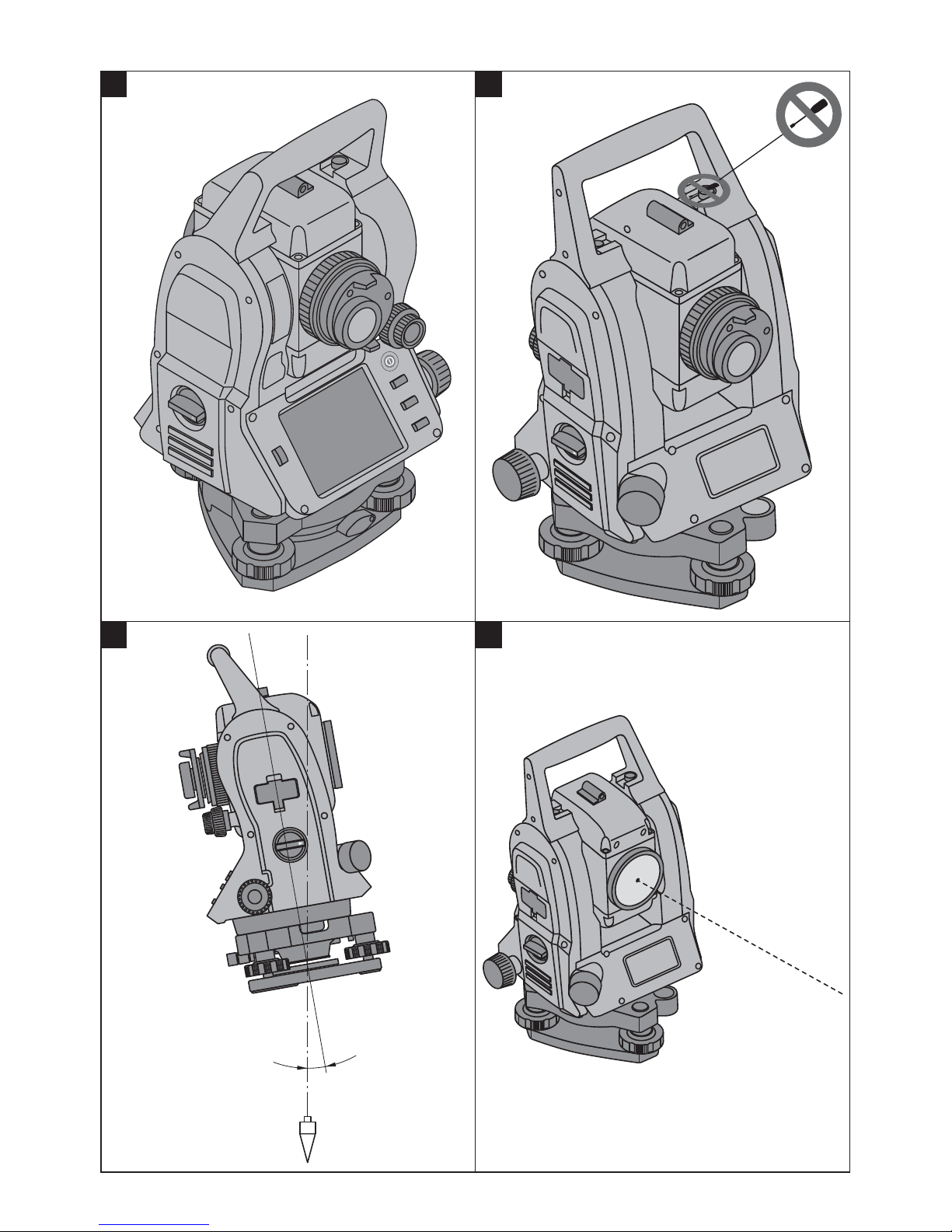
Rear casing section 1
Left battery compartment with cover retaining
@
screw
Tribrach footscrew
;
Tribrach lock
=
Touch screen control panel
%
Focussing knob
&
Eyepiece
(
Telescope with laser distancer
)
Alignment sight (sighting aid)
+
Front casing section 2
Vertical drive
/
USB interface connectors (small and large)
:
Right battery compartment with cover retaining
·
screw
Horizontal drive
$
Tribrach footscrew
£
Tribrach
|
Laser plummet
¡
Guide light
Q
Objective lens
W
Carrying handle
E
en
Contents
1 Generalinformation....................................................... 4
1.1 Safetynoticesandtheirmeaning.................................................. 4
1.2 Explanationofthepictogramsandotherinformation................................... 5
2 Description ................................................................ 5
2.1 Use of the product as directed . . .................................................. 5
2.2 Descriptionofthetool .......................................................... 5
2.3 Itemssuppliedasstandard ...................................................... 6
3 Accessories ............................................................... 6
4 Technicaldata............................................................. 8
5 Safetyinstructions ........................................................ 9
5.1 Basicinformationconcerningsafety ............................................... 9
5.2 Misuse...................................................................... 9
5.3 Properorganizationoftheworkarea.............................................. 10
5.4 Electromagnetic compatibility . . ................................................. 10
5.4.1 LaserclassificationforLaserClass2products ....................................... 10
5.4.2 LaserclassificationforLaserClass3Rproducts ...................................... 10
5.5 Generalsafetyrules........................................................... 10
5.6 Transport................................................................... 11
6 Descriptionofthesystem................................................ 11
6.1 Generalterms ............................................................... 11
6.1.1 Coordinates ................................................................ 11
6.1.2 Controllines................................................................ 11
1

6.1.3 Technicalterms.............................................................. 12
6.1.4 Telescope positions 43 ...................................................... 13
6.1.5 Termsandtheirdescription ..................................................... 13
6.1.6 Abbreviationsandtheirmeaning ................................................. 14
6.2 Anglemeasurementsystem..................................................... 15
6.2.1 Measuringprinciple........................................................... 15
en
6.2.2 Dual-axis compensator 5 ...................................................... 15
6.3 Distancemeasurement ........................................................ 15
6.3.1 Distance measurement 6 ...................................................... 15
6.3.2 Targets.................................................................... 16
6.3.3 Reflectorrod................................................................ 16
6.4 Heightmeasurement .......................................................... 17
6.4.1 Heightmeasurement.......................................................... 17
6.5 Guidelight .................................................................. 18
6.5.1 Guide light 7 ............................................................... 18
6.6 Laser pointer 6 .............................................................. 18
6.7 Datapoints.................................................................. 18
6.7.1 Selectingpoints ............................................................. 18
7 Firststeps ................................................................ 20
7.1 Batteries . . . ................................................................20
7.2 Charging the battery . . ........................................................ 20
7.3 Inserting and changing the battery 8 .............................................. 20
7.4 Checkingfunctions ........................................................... 20
7.5 Controlpanel................................................................ 20
7.5.1 Functionbuttons............................................................. 20
7.5.2 Sizeofthetouchscreen ....................................................... 21
7.5.3 Divisionofthetouchscreen..................................................... 21
7.5.4 Touchscreen–numericalkeyboard ............................................... 21
7.5.5 Touchscreen–alphanumericalkeyboard ........................................... 22
7.5.6 Touchscreen–generaloperatingcontrols .......................................... 22
7.5.7 Laserpointerstatusindicator.................................................... 22
7.5.8 Batteryconditionindicators..................................................... 22
7.6 Switchingon/off............................................................. 23
7.6.1 Switchingon................................................................ 23
7.6.2 Switchingoff................................................................ 23
7.7 Settingupthetool ............................................................ 23
7.7.1 Setting up over a mark on the floor or ground using the laser plummet . . .................... 23
7.7.2 Setting up the tool 9 .......................................................... 23
7.7.3 Settingupoverapipeusingthelaserplummet ....................................... 24
7.8 Theodolite application . ........................................................ 24
7.8.1 Settingthehorizontalcircledisplay................................................ 25
7.8.2 Enteringacirclereadingmanually ................................................ 25
7.8.3 Zeroingthecirclereading ...................................................... 26
7.8.4 Inclination indicator ......................................................... 26
8 Systemsettings .......................................................... 27
8.1 Configuration................................................................ 27
8.1.1 Settings ................................................................... 27
8.2 Timeanddate ............................................................... 29
9 Functionmenu(FNC)..................................................... 30
9.1 Guide light 7 ................................................................30
9.2 Laser pointer 6 .............................................................. 31
9.3 Display illumination . . . ........................................................ 31
2

9.4 Electronicbubblelevel......................................................... 31
9.5 Correctionofatmosphericinfluences ............................................. 31
9.5.1 Correctionofatmosphericinfluences .............................................. 32
10 Functionsrequiredforvarious applications ............................ 32
10.1 Projects .................................................................... 32
10.1.1 Showingtheactiveproject...................................................... 32
10.1.2 Selectingaproject ........................................................... 33
10.1.3 Creatinganewproject......................................................... 33
10.1.4 Projectinformation ........................................................... 34
10.2 Setting a station and orientation ................................................. 34
10.2.1 Overview .................................................................. 34
10.2.2 Settingastationoverapointwithcontrollines ....................................... 35
10.2.3 Settingastation“anywhere”,withbuildingcontrollines................................. 38
10.2.4 Settingastationoverapointwithcoordinates........................................ 41
10.2.5 Settingastation“anywhere”,withcoordinates ....................................... 43
10.3 Settingtheheight............................................................. 46
10.3.1 Settingastationwithacontrolline(heightoption“on”) ................................. 46
10.3.2 Settingastationwithcoordinates(heightoption“on”) .................................. 48
11 Applications .............................................................. 50
11.1 Horizontallayout(Horz.layout) .................................................. 50
11.1.1 Thehorizontallayoutprinciple ................................................... 50
11.1.2 Layingoutwithbuildingcontrollines .............................................. 51
11.1.3 Layingoutwithcoordinates ..................................................... 54
11.2 Verticallayout(Vert.layout) ..................................................... 57
11.2.1 Theverticallayoutprinciple ..................................................... 57
11.2.2 Verticallayoutwithbuildingcontrollines............................................ 58
11.2.3 Verticallayoutwithcoordinates .................................................. 61
11.3 As-built .................................................................... 63
11.3.1 Theprincipleof“As-built” ...................................................... 63
11.3.2 As-builtwithbuildingcontrollines ................................................ 64
11.3.3 As-builtwithcoordinates....................................................... 66
11.4 Missingline ................................................................. 67
11.4.1 Theprincipleof“Missingline” ................................................... 67
11.5 Measureandrecord........................................................... 70
11.5.1 Theprincipleof“Measureandrecord” ............................................. 70
11.5.2 Measureandrecordwithbuildingcontrollines ....................................... 70
11.5.3 Measureandrecordwithcoordinates.............................................. 72
11.6 Verticalalignment ............................................................ 73
11.6.1 Theprincipleof“Verticalalignment” ............................................... 73
11.7 Areameasurement............................................................ 74
11.7.1 Theprincipleofareameasurement................................................ 74
11.8 Indirectheightmeasurement.................................................... 76
11.8.1 Theprincipleofindirectheightmeasurement ........................................ 76
11.8.2 Indirectheightmeasurement .................................................... 77
11.9 Determiningapointinrelationtoanaxis........................................... 78
11.9.1 Theprincipleof“Pointinrelationtoaxis” ........................................... 78
11.9.2 Determiningtheaxis .......................................................... 78
11.9.3 Checkingpointsinrelationtotheaxis.............................................. 79
12 Dataanddatahandling .................................................. 80
12.1 Introduction ................................................................. 80
en
3

12.2 Pointdata................................................................... 80
12.2.1 Pointsintheformofmeasuredpoints.............................................. 80
12.2.2 Pointsintheformofcoordinatepoints ............................................. 80
12.2.3 Pointswithgraphicalelements................................................... 80
12.3 Generationofpointdata........................................................ 80
12.3.1 Withthetotalstation .......................................................... 80
en
12.3.2 WithHiltiPROFISLayout....................................................... 81
12.4 Datamemory................................................................ 81
12.4.1 Totalstationinternalmemory.................................................... 81
12.4.2 USBmemory ............................................................... 81
13 Totalstationdatamanager .............................................. 81
13.1 Overview ................................................................... 81
13.2 Selectingajob............................................................... 82
13.2.1 Fixedpoints(controlpointsorlayoutpoints)......................................... 83
13.2.2 Measuredpoints............................................................. 84
13.3 Deletingaproject............................................................. 86
13.4 Creatinganewproject......................................................... 87
13.5 Copyingaproject............................................................. 87
14 ExchangingdatawithaPC .............................................. 88
14.1 Introduction ................................................................. 88
14.2 HILTIPROFISLayout.......................................................... 88
14.2.1 Datatypes ................................................................. 88
14.2.2 HiltiPROFISLayoutdataoutput(export)............................................ 89
14.2.3 HiltiPROFISLayoutdatainput(import)............................................. 89
15 Calibrationandadjustment.............................................. 89
15.1 In-the-fieldcalibration ......................................................... 89
15.2 In-the-fieldcalibration ......................................................... 90
15.3 HiltiCalibrationService ........................................................ 92
16 Careandmaintenance................................................... 93
16.1 Cleaninganddrying........................................................... 93
16.2 Storage .................................................................... 93
16.3 Transport................................................................... 93
17 Disposal................................................................... 93
18 Manufacturer’swarranty................................................. 94
19 FCC statement (applicable in US) / IC statement (applicable in
Canada)................................................................... 94
20 ECdeclarationofconformity (original).................................. 95
1 General information
1.1 Safety notices and their meaning
DANGER
Draws attention to imminent danger that will lead to
seriousbodilyinjuryorfatality.
WARNING
Draws attention to a potentially dangerous situation that
could lead to serious personal injury or fatality.
4
CAUTION
Draws attention to a potentially dangerous situation that
could lead to slight personal injury or damage to the
equipment or other property.
NOTE
Draws attention to an instruction or other useful information.
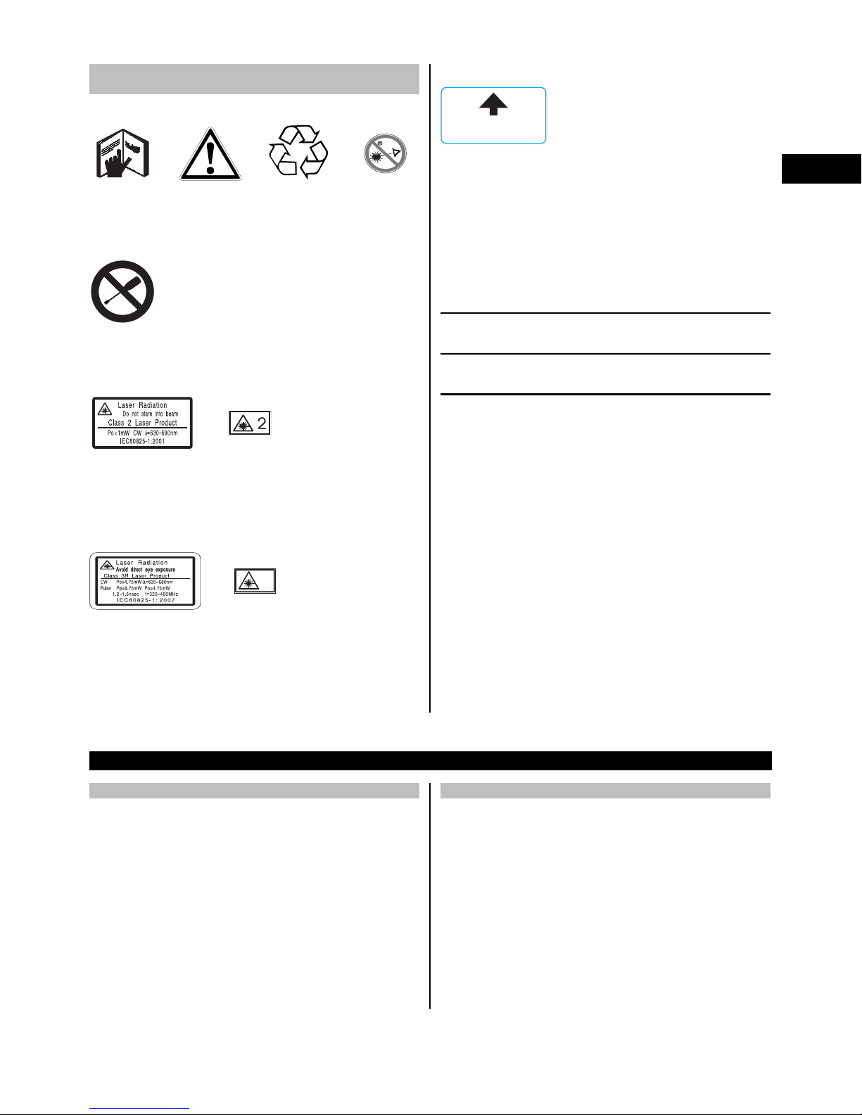
1.2 Explanation of the pictograms and other
information
Symbols
Read the
operating
instructions
before use.
General
warning
Return waste
material for
recycling.
>1/4s
Do not look
into the
beam.
Laser exit aperture
/$6(5$3(5785(
Laser exit aperture
Location of identification data on the tool
The type designation and serial number can be found on
thetypeidentificationplateonthetool.Makeanoteof
this data in your operating instructions and always refer
to it when making an enquiry to your Hilti representative
or service department.
Type:
en
Do not turn
the screw
Symbol for Laser Class II / Class 2
Laser class II
according to
CFR 21, § 1040
(FDA)
Laser class 2
according to
EN 60825:2008
Symbol for Laser Class III / Class 3
3R
Laser class II
according to
CFR 21, § 1040 (FDA)
Do not look
into the
beam with
the naked
eye or with
optical
instruments.
Generation: 01
Serial no.:
2 Description
2.1 Use of the product as directed
The tool is designed for measuring distances and directions, calculating target positions in 3 dimensions and
the values derived from these positions and for laying
out points using given coordinates or values relative to a
control line.
To avoid the risk of injury, use only genuine Hilti accessories and insert tools.
Observe the information printed in the operating instructions concerning operation, care and maintenance.
Take the influences of the surrounding area into account.
Donotusetheappliancewherethereisariskoffireor
explosion.
Modification of the tool is not permissible.
2.2 Description of the tool
The POS 15/18 total station can be used to determine the
exact position of objects or points. The tool is equipped
with horizontal and vertical circles with digital graduation,
two electronic levels (compensators), a coaxial laser distancer incorporated in the telescope and an electronic
processor system for calculating and saving data.
Hilti PROFIS Layout, a PC application provided by Hilti,
can be used to transfer data in both directions between
the total station and a PC, for data processing and for
exporting data to other systems.
5
en
2.3 Items supplied as standard
1 Total station
1 AC adapter incl. charging cable for chargers
1Charger
2 3.8 V 5200 mAh Li-ion battery
1 Reflector rod
1 POW 10 adjusting key
2 Laser warning plate
1 Manufacturer’s certificate
1 Operating instructions
1 Hilti toolbox
1 Optional: Hilti PROFIS Layout (PC software on
CD‑ROM)
1 Optional: Copy protection dongle for PC soft-
ware
1 Optional: USB data cable
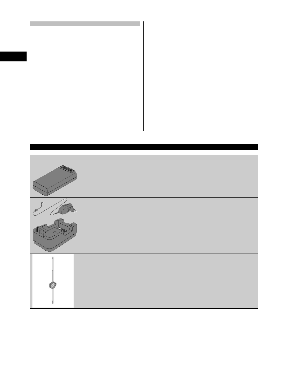
3 Accessories
Illustration Designation Description
POA 80 battery
POA 81 AC adapter
POA 82 charger
POA 50 reflector rod (metric) The POA 50 (metric) reflector rod
(consisting of four sections (each
with a length of 300 mm), the rod
point (length 50 mm) and the reflector
plate (height 100 mm or, respectively,
50 mm to the middle)) is used to take
readings from points on the ground.
6
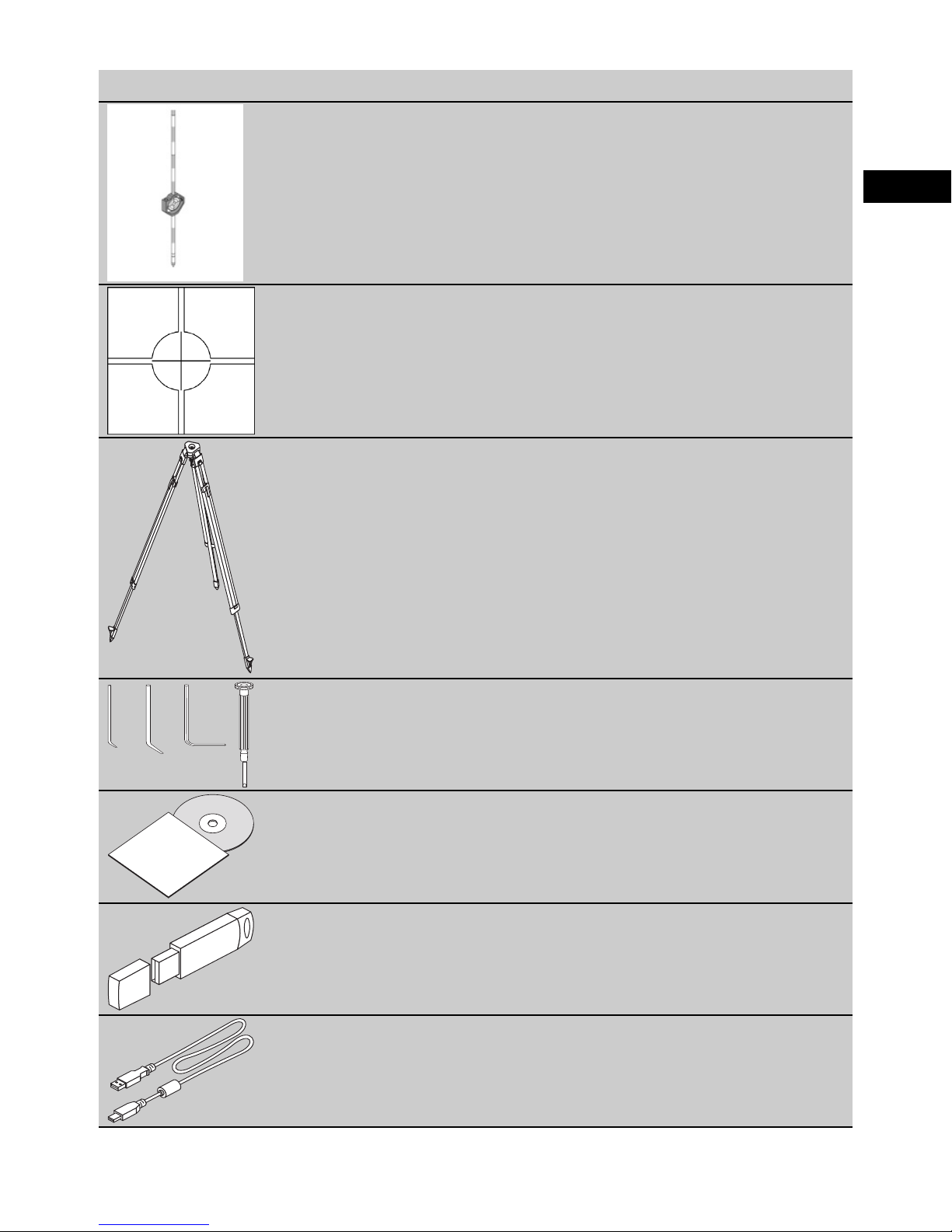
Illustration Designation Description
POA 51 reflector rod (imperial) The POA 51 (imperial) reflector rod
(consisting of four sections (each with
alengthof12"),therodpoint(length
2.03") and the reflector plate (height
3.93" or, respectively, 1.97" to the
middle)) is used to take readings from
points on the ground.
POAW‑4 reflector foil A self-adhesive foil for placing refer-
ence points on raised targets such as
walls or posts.
PUA 35 tripod
en
POW 10 adjusting key For use by appropriately experienced
persons only!
Hilti PROFIS Layout PC application that allows positions
(points) to be generated from CAD
data and transferred to the tool.
POA 91 copy protection dongle
POW 90 data cable
7

4 Technical data
Right of technical changes reserved.
NOTE
The only difference between the two tools is their angle measurement accuracy.
en
Telescope
Telescope magnification 30x
Shortest target distance 1.5 m (4.9 ft)
Telescope angle of view 1° 20': 2.3 m / 100 m (7.0 ft / 300 ft)
Objective lens aperture 45 mm (1.8")
Compensator
Type Dual-axis, liquid
Working range
Accuracy 2"
Angle measurement
POS 15 accuracy (DIN 18723) 5"
POS 18 accuracy (DIN 18723) 3"
Angle reading system Diametral
±3’
Distance measurement
Range
Accuracy ±3 mm + 2 ppm (0.01 ft + 2 ppm)
Laser class Class 3R, visible, 630-680 nm, Po < 4.75 mW, f = 320-
Guide light
Aperture angle 1.4°
Typical range 70 m (230 ft)
Laser plummet
Accuracy 1.5 mm at 1.5 m (1/16 at 3 ft)
Laser class Class 2, visible, 635 nm, Po < 10 mW (EN 60825-1/ IEC
Data memory
Memory size (data blocks) 10,000
Data transfer interfaces Host and client, 2 x USB
Display
Type Color display (touch screen), 320 x 240 pixels
Illumination 5 levels
Contrast Day / night mode selectable
340 m (1000 ft) Kodak 90% gray
400 MHz (EN 60825-1/ IEC 60825-1); Class III (CFR 21
§ 1040 (FDA))
60825-1); Class II (CFR 21 §1040 (FDA)
IP protection class
Class IP 56
8

Horizontal drive
Type Continuous
Tripod thread
Tribrach thread 5/8''
POA 80 battery
Type Li-ion
Rated voltage 3.8 V
Battery capacity 5,200 mAh
Charging time 4 h
Battery life (with distance / angle measurement every
30 seconds)
Weight 0.1 kg (0.2 lbs)
Dimensions 67 mm x 39 mm x 25 mm (2.6" x 1.5" x 1.0")
POA 81 AC adapter and POA 82 charger
AC supply 100…240 V
AC frequency 47…63 Hz
Rated current input 4 A
Rated voltage 5 V
Weight (POA 81 AC adapter) 0.25 kg (0.6 lbs)
Weight (POA 82 charger) 0.06 kg (0.1 lbs)
Dimensions (POA 81 AC adapter) 108 mm x 65 mm x 40 mm (4.3" x 2.6" x 0.1")
Dimensions (POA 82 charger) 100 mm x 57 mm x 37 mm (4.0" x 2.2" x 1.5")
16 h
en
Temperature
Operating temperature range -20…+50°C (-4°F to +122°F)
Storage temperature range -30…+70°C (-22°F to +158°F)
Dimensions and weights
Dimensions 149 mm x 145 mm x 306 mm (5.9" x 5.7" x 12")
Weight 4.0 kg (8.8 lbs)
5 Safety instructions
5.1 Basic information concerning safety
In addition to the information relevant to safety given
in each of the sections of these operating instructions,
the following points must be strictly observed at all
times.
5.2 Misuse
The tool and its ancillary equipment may present hazards
when used incorrectly by untrained personnel or when
used not as directed.
a) Never use the tool without having received the ap-
propriate instruction on its use or without having
read these operating instructions.
b) Do not render safety devices ineffective and do
not remove information and warning notices.
c) Have the tool repaired only at a Hilti Service Center.
Failure to follow the correct procedures when
9

opening the tool may cause emission of laser
radiation in excess of class 3R.
d) Modification of the power tool or tampering with its
parts is not permissible.
e) The grip is designed to have a certain amount of play
at one side. This is not a fault. It serves to protect
en
the alidade. Tightening the screws on the grip may
cause damage to the thread, making costly repairs
necessary. Do not tighten any screws on the grip!
f) To avoid the risk of injury, use only genuine Hilti
accessories and additional equipment.
g) Do not use the tool in areas where there is a
danger of explosion.
h) Use only clean, soft cloths for cleaning. If necessary,
they may be moistened with a little alcohol.
i) Keep laser tools out of reach of children.
j) Measurements to plastic foam surfaces, e.g. poly-
styrene foam, to snow or to highly reflective surfaces,
may result in incorrect readings.
k) Measurements taken to surfaces with low reflectivity
in highly reflective surroundings may be inaccurate.
l) Measurements taken through panes of glass or other
objects may be inaccurate.
m) Rapid changes in the conditions under which the
measurement is taken, e.g. persons walking through
the laser beam, may lead to inaccurate results.
n) Do not point the tool toward the sun or other powerful
light sources.
o) Do not use the tool as a level.
p) Check the tool before taking important measure-
ments or after it has been dropped or subjected to
mechanical effects such as impact or vibration.
5.3 Proper organization of the work area
a) Secure the area in which you are working and take
care to avoid directing the beam toward other per-
sons or toward yourself when setting up the tool.
b) Use the tool only within the defined application limits,
i.e. do not take readings from mirrors, stainless steel
or polished stone, etc.
c) Observe the accident prevention regulations applic-
able in your country.
5.4 Electromagnetic compatibility
Although the tool complies with the strict requirements
of the applicable directives, Hilti cannot entirely rule out
the possibility of the tool
- causing interference to other devices (e.g. aircraft nav-
igation equipment) or being subject to
- interference caused by powerful electromagnetic radi-
ation, leading to incorrect operation.
Check the accuracy of the tool by taking measurements
by other means when working under such conditions or
if you are unsure.
5.4.1 Laser classification for Laser Class 2
products
The laser plummet incorporated in the tools conforms
to Laser Class 2 based on the IEC825-1 / EN60825-
01:2008 standard and to CFR 21 § 1040 (Laser Notice
50). The eyelid closure reflex protects the eyes when a
person looks into the beam unintentionally for a brief
moment. This eyelid closure reflex, however, may be
negatively affected by medicines, alcohol or drugs. This
tool may be used without need for further protective
measures. Nevertheless, as with the sun, one should not
look directly into sources of bright light. Do not direct the
laser beam toward persons.
5.4.2 Laser classification for Laser Class 3R
products
The measuring laser incorporated in the tools for distance
measurement conforms to Laser Class 3R based on the
IEC825-1 / EN60825-1:2008 standard and to CFR 21 §
1040 (Laser Notice 50). This tool may be used without
need for further protective measures.Do not stare into the
beam and do not direct the beam toward other persons.
a) Tools of the laser class 3R and class IIIa should be
operated by trained personnel only.
b) Theareainwhichthetoolisinusemustbemarked
with laser warning signs.
c) The plane of the laser beam should be well above or
well below eye height.
d) Precautions must be taken to ensure that the laser
beam does not unintentionally strike highly reflective
surfaces.
e) Precautions must be taken to ensure that persons do
not stare directly into the beam.
f) The laser beam must not be allowed to project bey-
ond the controlled area.
g) When not in use, laser tools should be stored in an
area to which unauthorized persons have no access.
5.5 General safety rules
a) Check the tool for damage before use. If the tool
is found to be damaged, have it repaired at a Hilti
service center.
b) Operating and storage temperatures must be ob-
served.
c) Check the accuracy of the tool after it has
been dropped or subjected to other mechanical
stresses.
d) When the tool is brought into a warm environment
from very cold conditions, or vice-versa, allow it
to become acclimatized before use.
e) When a tripod is used, check that the tool is
securely mounted (screwedon) and thatthe tripod
stands securely on solid ground.
f) Keep the laser exit aperture clean to avoid meas-
urement errors.
g) Although the tool is designed for the tough condi-
tions of jobsite use, as with other optical and electronic instruments (e.g. binoculars, spectacles,
cameras) it should be treated with care.
h) Although the tool is protected to prevent entry
of dampness, it should be wiped dry each time
before being put away in its transport container.
i) As a precaution, check the previous settings or
any adjustments you may have made.
10
j) View the tool at an angle when setting it up with
the aid of the circular bubble level.
k) Secure the battery compartment cover carefully
in order to ensure that the battery cannot fall
out and that no contact can occur which would
result in the tool being switched off inadvertently
possibly resulting in loss of data.
5.6 Transport
The batteries must be insulated or removed from the
tool before the tool is shipped or sent by mail. Leaking
batteries may damage the tool.
To avoid pollution of the environment, the tool and the
batteriesmustbedisposedofinaccordancewiththe
currently applicable national regulations.
Consult the manufacturer if you are unsure of how to
proceed.
6 Description of the system
6.1 General terms
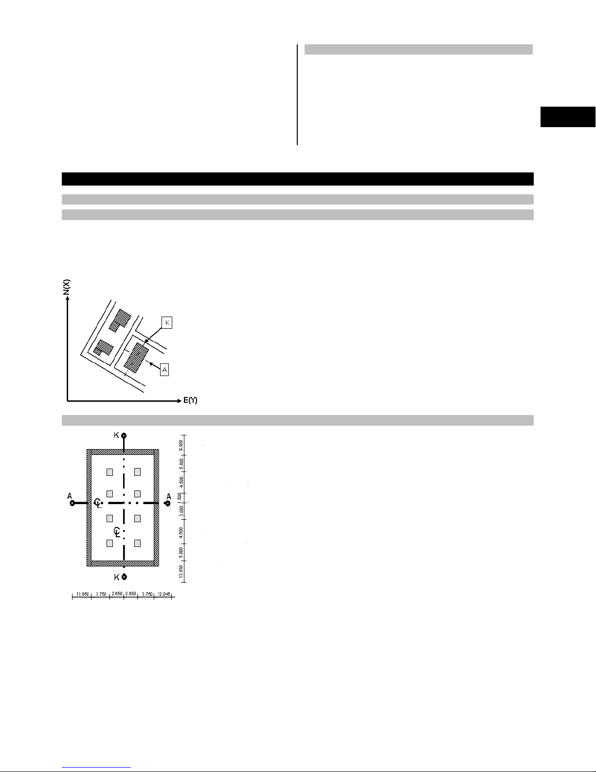
6.1.1 Coordinates
On some construction sites, instead of or in combination with control lines, additional points are marked out and their
positions described by coordinates.
The coordinates used are generally based on the national coordinate system which is also usually taken as a basis for
maps of the country.
en
6.1.2 Control lines
Height marks and control lines are generally marked out on and around the building plot by a surveyor before
construction begins.
Two ends are marked on the ground for each control line.
These marks are used to position the individual components of the building or structure. Large buildings require a
number of control lines.
11
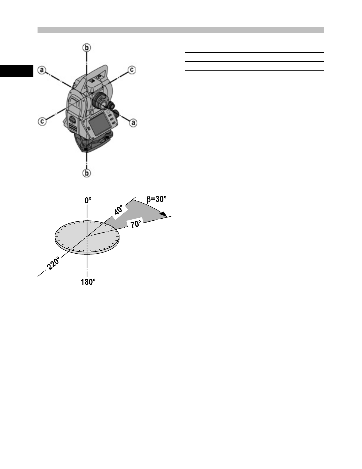
6.1.3 Technical terms
Tool axes
en
Horizontal circle / horizontal angle
aSightingaxis
bVerticalaxis
c Trunnion (tilt axis)
The included angle of 70°- 40° = 30° can be calculated from the horizontal circle readings of 70° to one target and 30°
to the other target.
12

Vertical circle / vertical angle
As the vertical circle is aligned at 0° to the direction of gravity or at 0° to horizontal, angles are determined relative to
the direction of gravity, so to speak.
Using these values, the horizontal distance and vertical distance are calculated from the measured slope distance.
en
6.1.4 Telescope positions 43
The term “telescope position” is used to ensure that readings from the horizontal circle can be correctly assigned to
the vertical angle, i.e. the position of the telescope relative to the control panel determines in which “position” the
measurements have been taken.
When the display and the eyepiece are immediately in front of you, then the tool is in telescope position 1. 4
When the display and the objective lens are immediately in front of you, then the tool is in telescope position 2. 3
6.1.5 Terms and their description
Sighting axis The line through the cross hairs and center of the objective lens (tele-
scope axis).
Trunnion The telescope pivot (tilt) axis.
Vertical axis The pivot axis of the entire tool.
Zenith The zenith is the point that lies in the direction of gravity, but in the op-
posite, upward direction.
Horizon The horizon is the direction perpendicular to the direction of gravity –
generally known as horizontal.
Nadir Nadir is the name given to the downward direction in which gravity acts.
Vertical circle The vertical circle is the circle of angles described by the telescope when
it is tilted upwards or downwards.
Vertical direction A reading taken from the vertical circle is known as the vertical direction.
Vertical angle (VA) A vertical angle is a reading from the vertical circle.
The vertical circle is usually aligned with the direction of gravity with the
aid of the compensator, with the zero point at the zenith.
Elevation angle An elevation angle of zero refers to the horizon (horizontal plane). Positive
angles are above horizontal (upwards) and negative angles are below
horizontal (downwards).
Horizontal circle The horizontal circle is the complete circle of angles described by the
tool when it is rotated.
Horizontal direction A reading taken from the horizontal circle is known as the horizontal dir-
ection.
13

en
Horizontal angle (HA) A horizontal angle is the difference between two readings from the ho-
rizontal circle. However, a reading from one of the circles is also often
described as an angle.
Slopedistance(SD) Distancefromthecenterofthetelescopetothepointat which the laser
beam strikes the target surface
Horizontal distance (HD) The horizontal distance derived from the measured slope distance.
Alidade The rotatable center part of the total station is known as the alidade.
This part usually carries the control panel, bubble levels for leveling and,
inside, the horizontal circle.
Tribrach The tool stands on the tribrach which, for example, can be mounted on a
tripod.
The tribrach has three points of contact which can be adjusted vertically
by adjusting screws.
Tool standpoint This is the point at which the tool is set up - usually over a point marked
on the ground.
Station height (Stat H) The height of the point on the ground at the tool station (above a refer-
ence height).
Instrument height (HI) The height from the point on the ground or floor to the center of the tele-
scope.
Reflector height (HR) The distance from the center of the reflector to the tip of the reflector
rod.
Orientation (backsight) point The target point used in conjunction with the tool station to determine
the horizontal reference direction for the horizontal angle measurement.
EDM Electronic Distance Measurer (laser distancer / range meter).
East (E) In a typical surveying coordinate system this value refers to the east-
west direction.
North (N) In a typical surveying coordinate system this value refers to the north-
south direction.
Line (L) This is the term used to describe a longitudinal measurement along a
building control line or other reference line.
Offset (O) This is the term used for a distance at right angles to a control line or
other reference line.
Height (H) Many values are referred to as heights.
A height is a vertical distance from a reference point or reference surface.
6.1.6 Abbreviations and their meaning
HA Horizontal angle
VA Vertical angle
dHA Delta horizontal angle
dVA Delta vertical angle
SD Slope distance
HD Horizontal distance
dHD Delta horizontal distance
HI Instrument height
HR Reflector height
BM height Benchmark height
Stat H Station height
hHeight
EEast
NNorth
O Offset
lLinevalue
14
dH Delta height
dE Delta east
dN Delta north
dOffs Delta offset horz
dL Delta line
6.2 Angle measurement system
6.2.1 Measuring principle
The tool calculates the angle in each case from two circle readings.
For the purpose of distance measurement, pulses transmitted along a visible laser beam at a certain wavelength are
reflected from the object to which the measurement is being taken.
Distances can be determined from the values obtained from these pulses.
en
Tool inclination is determined with the aid of electronic levels (compensators), circle readings are corrected accordingly
and the height difference is also calculated from the measured slope distance and horizontal distance.
The built-in microprocessor system allows conversion of all distance units between the metric and imperial systems
(feet, yards, inches, etc.) and digital circle graduation allows various angle units to be shown, e.g. 360° sexagesimal
graduation (° ’ ") or gon (g) in which the full circle consists of 400g graduations.
6.2.2 Dual-axis compensator 5
A compensator is, in principle, an electronic leveling system that determines exactly the remaining inclination (“off
level”) of the axes of the total station after it has been set up.
The dual-axis compensator determines this remaining inclination of the tool with great accuracy in the line and offset
axes.
All calculations are then corrected automatically to ensure that this remaining inclination has no influence on angle
measurements.
6.3 Distance measurement
6.3.1 Distance measurement 6
Distance measurement is by way of a visible laser beam emitted through the center of the objective lens, i.e the laser
distancer is coaxial.
15
en
The laser beam takes measurements to “normal” surfaces without need for a special reflector.
“Normal” surfaces are considered to be those that are not highly reflective. These surfaces may have a rough texture.
Range depends on the reflectivity of the target surface, i.e. only slightly reflective surfaces such as those with a blue,
red or green color may reduce the effective range.
The tool is supplied complete with a reflector rod to which an adhesive reflective foil is attached.
Taking readings from this reflector ensures reliable distance measurements even at long range.
The reflector rod also allows distance measurements to be taken to points marked on the ground.
NOTE
Check at regular intervals to ensure that the visible laser distancer beam is correctly adjusted and in line with the
sighting axis. Send the tool to your nearest Hilti Service Center if adjustment is found necessary or if you are unsure.
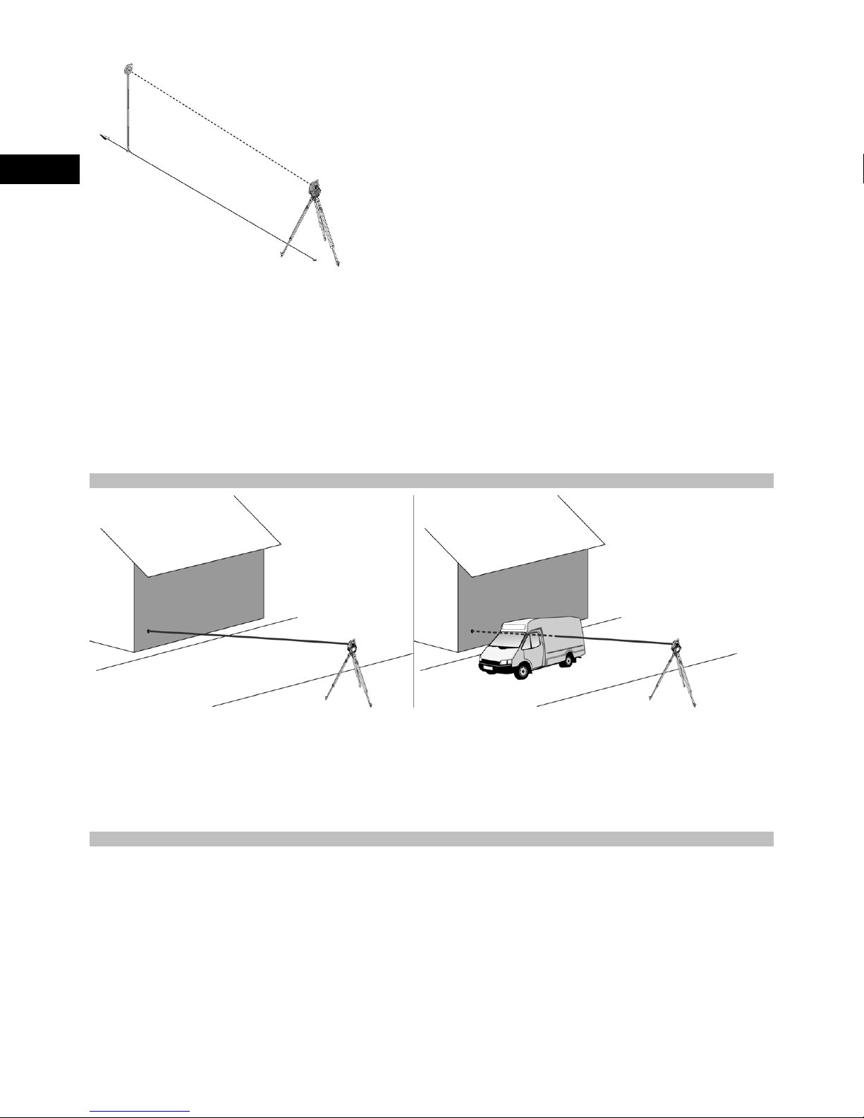
6.3.2 Targets
The laser beam is capable of measuring to any stationary target.
While a distance is being measured care must be taken to ensure that no other object moves through the laser beam.
NOTE
There is otherwise a risk that the distance will be measured to another object, not to the desired target.
6.3.3 Reflector rod
The POA 50 (metric) reflector rod (consisting of four sections (each with a length of 300 mm), the rod point (length
50 mm) and the reflector plate (height 100 mm or, respectively, 50 mm to the middle)) is used to take readings from
points on the ground.
The POA 51 (imperial) reflector rod (consisting of four sections (each with a length of 12" ), the rod point (length 2.03")
and the reflector plate (height 3.93" or, respectively, 1.97" to the middle)) is used to take readings from points on the
ground.
The reflector rod can be held perpendicular to the ground or floor with the aid of the built-in bubble level.
In order to ensure an unobstructed line of sight for the laser beam, the distance between the tip of the rod and the
center of the reflector can be varied.
The pattern printed on the reflector foil ensures reliable measurement of distances and directions and allows a longer
range than is possible with other target surfaces.
16

Reflector rod
lengths
POA 50 (metric) 100 mm 400 mm 700 mm 1,000 mm 1,300 mm
POA 51 (imper-
ial)
L1 L2 L3 L4 L5
4" 16" 28" 40" 52"
en
6.4 Height measurement
6.4.1 Height measurement
The tool can be used to measure heights or differences in height.
Height measurements are made using the trigonometrical height measurement principle and are calculated accordingly.
The height measurements take the vertical angleand the slope distance in conjunction with the instrument height
and thereflector height into account.
dH = COS(VA)*SD+HI−HR+(corr)
In order to calculate the absolute height of the target point (point on the ground), the station height (Stat H) is added
to the delta height.
H=StatH+dH
17

6.5 Guide light
6.5.1 Guide light 7
The guide light can be switched on or off manually and the blink frequency adjusted to one of 4 different settings.
The guide light consists of two red LEDs incorporated in the telescope unit.
When switched on, one of the two LEDs blinks to clearly indicate whether the person is to the right or left of the
sighting line.
en
A person at a distance of at least 10 m from the tool and standing approximately on the sighting line will see either the
blinking or steady light more brightly, depending on whether they are positioned to the right or left of the sighting line.
The person is positioned on the sighting line when both LEDs are seen to have the same intensity.
6.6 Laser pointer 6
The laser beam projected by the tool can also be switched on permanently.
When switched on permanently, the laser beam is often referred to as a “laserpointer”.
When working indoors, the laser pointer can also be used as an aiming device or, respectively, to indicate the direction
in which measurements are being made.
Outdoors, however, the beam is visible only under certain conditions so its use for this purpose is not really feasible.
6.7 Data points
The data from measurements taken with the Hilti total stations is used to generate measured points.
Similarly, these measured points and their position descriptions are used in applications such as “Layout” or to define
station locations.
Hilti total stations incorporate various features that facilitate and speed up the process of selecting points.
6.7.1 Selecting points
Point selection forms an important integral part of a total station system as points are generally measured and used
repeatedly for laying out, for stations, as orientation aids and for comparative measurements.
Points can be selected in a number of different ways:
1. From a plan
2. From a list
3. Manual entry
Selecting points from a plan
Control points (fixed points) are available for selection in graphical form.
Points can be selected on the display by touching them with a finger or the point of a stylus.
Shows the point selected from
the graphical display.
Cancel and return to previous
screen.
Select a point by manual entry.
Confirm and apply the entry.
Show all points in the display
area.
18

Select a point from a list.
Zoom in.
Zoom out.
Enlarge the selected area.
NOTE
Point data assigned to a graphical element cannot be edited or deleted on the total station. This can only be done
using Hilti PROFIS Layout.
Selecting points from a list
Cancel and return to previous
screen.
Selectapointfromaplan.
Select a point by manual entry.
en
Manual entry of points
Confirm and apply the entry.
Cancel and return to previous
screen.
Selectapointfromaplan.
Select a point from a list.
Confirm and apply the entry.
19

7Firststeps
7.1 Batteries
The tool is equipped with two batteries which can supply power one after the other.
The current state of battery charge (both batteries) is always shown.
When changing batteries, one battery can remain in the tool and continue to provide power while the other battery is
en
being charged.
When changing batteries while the tool is in operation and to prevent the tool switching itself off, it is recommended
that the batteries are changed one after the other.
7.2 Charging the battery
After unpacking the tool, remove the AC adapter, charger and battery from their holders.
Charge the battery for approx. 4 hours.
7.3 Inserting and changing the battery 8
Insert the charged battery into the tool with the battery connector underneath and facing the tool.
Secure the battery compartment cover carefully.
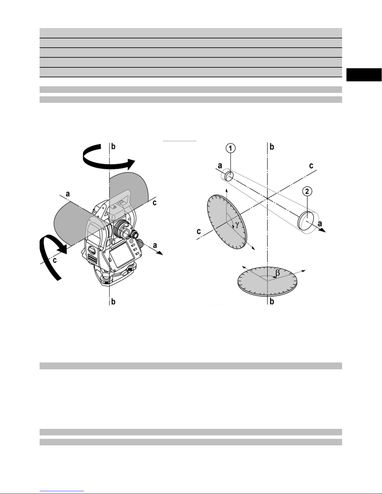
7.4 Checking functions
NOTE
Please note that this tool makes use of friction clutches for pivoting about the alidade and thus does not have to be
locked at the horizontal drives.
The horizontal and vertical drives are of the continuous type, similar to those of an optical level.
Check the functions of the tool before initial use and at regular intervals in accordance with the following criteria:
1. Pivot the tool carefully by hand to the left and right and tilt the telescope up and down to check operation of the
friction clutches.
2. Turn the horizontal and vertical drives carefully in both directions.
3. Turn the focussing ring fully to the left. Look through the telescope and turn the eyepiece ring to bring the cross
hairs into focus.
4. With a little practice you can check the two optical sights on the telescope to ensure that they are in alignment
with the object targeted by the cross hairs.
5. Check to ensure that the cover for the USB interfaces is closed securely before further use of the tool.
6. Check that the screws on the carrying handle are tight.
7.5 Control panel
The control panel consists of a total of 5 buttons with symbols plus a touch screen for interactive operation.
7.5.1 Function buttons
The function buttons are used for general operation of the tool.
Switch the tool on or off.
Switch the display backlight on
or off.
Select the FNC menu for additional settings.
Cancel or end all active
functions and return to the start
menu.
Showthehelptextforthecurrent screen.
20
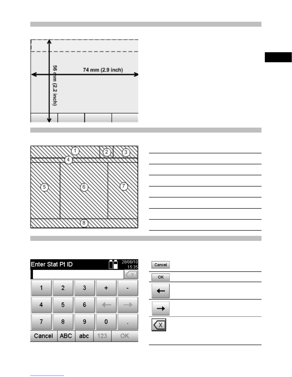
7.5.2 Size of the touch screen
The touch screen is approx. 74 x 56 mm (2.9 x 2.2 in) in size and has a resolutionof320x240pixels.
7.5.3 Division of the touch screen
The touch screen is divided into areas for operation of the tool and for displaying information to the user.
Instructions and info for the user
@
Battery and laser pointer status indicator
;
en
Time and date indicator and entry line
=
Menu hierarchy
%
Data field designations in
&
Data fields
(
Drawings to assist measuring operations
)
Bar containing up to 5 touch screen buttons
+
7.5.4 Touch screen – numerical keyboard
When numerical data is required to be entered, the appropriate keyboard appears in the display automatically.
The keyboard layout is as shown in the illustration below.
Cancel and return to previous
screen.
Confirm and apply the entry.
Move the cursor to the left.
Move the cursor to the right.
(
Delete the character to the left
of the cursor position. If there
is no character to the left, the
character at the cursor position
will be deleted.
21

7.5.5 Touch screen – alphanumerical keyboard
When alphanumerical data is required to be entered, the appropriate keyboard appears in the display automatically.
The keyboard layout is as shown in the illustration below.
Cancel and return to previous
en
7.5.6 Touch screen – general operating controls
Application button - used to start an application or function.
screen.
Switch to lower case letters.
Switch to numerical keys.
Confirm and apply the entry.
Move the cursor to the left.
Move the cursor to the right.
Delete the character to the left
of the cursor position. If there
is no character to the left, the
character at the cursor position
will be deleted.
Button for direct entry of numerical data, including symbols and decimal
points.
Button for direct entry of alphanumerical characters, including upper and
lower cases.
Select from a list. These lists may contain numerical or alphanumerical
values and settings.
A drop-down menu. In most cases, these menus provide a maximum of
three options for the selection of settings.
Example of a button in the bottom line of the display.
7.5.7 Laser pointer status indicator
The tool is equipped with a laser pointer.
Laser pointer ON
Laser pointer OFF
7.5.8 Battery condition indicators
The tool uses 2 lithium-ion batteries which can supply power at the same timeoroneaftertheother,dependingon
requirements.
The tool switches from one battery to the other automatically.
One of the batteries can thus be removed at any time, e.g. for charging, whilecontinuingtousethetoolwiththeother
battery - so long as its capacity allows.
NOTE
The state of battery charge is indicated by the extent to which the battery symbol is “filled”.
22
7.6 Switching on / off
7.6.1 Switching on
Press and hold the on/off button for approx. 2 seconds.
NOTE
If the tool is starting from a fully switched-off state, the complete start-up procedure takes approx. 20 – 30 seconds,
during which two different screens are displayed consecutively.
The end of the start-up procedure has been reached when the tool shows that it requires to be leveled (see section
7.7.2).
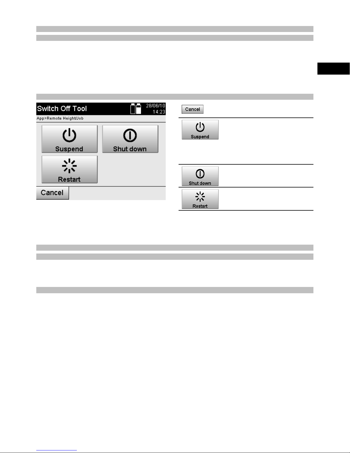
7.6.2 Switching off
Cancel and return to previous
screen.
The total station goes into sleep
mode. When the on / off button is again pressed the system
goes back into normal operating
mode and returns to the place
it was at before entering sleep
mode.
Switch off the total station completely.
The total station will be restarted. Any data not already saved
will be lost.
en
Press the on / off button.
NOTE
Please note that when switching off or restarting, the user is asked to confirm this action, just to be sure.
7.7 Setting up the tool
7.7.1 Setting up over a mark on the floor or ground using the laser plummet
The tool should always be set up over a point marked on the floor or ground so thatincaseofmeasurementdeviations
it is possible to fall back on the data for the station or orientation point.
The tool features a laser plummet that is switched on automatically together with the tool.
7.7.2 Setting up the tool 9
1. Set up the tripod with the center of the tripod head approximately over thepointmarkedontheground.
2. Mount the tool on the tripod by tightening the tripod screw and then switchthetoolon.
3. Move two of the tripod legs with your hands until the laser beam strikes the mark on the ground.
NOTE Take care to ensure that the tripod head remains approximately horizontal.
4. Then press the points of the tripod legs into the ground by applying pressure with your foot.
5. Adjust the footscrews to eliminate any deviation of the laser point from the mark on the ground. The laser point
must then be exactly in the center of the mark on the ground.
6. The circular bubble level can be centered by adjusting the tripod legs.
NOTE This is done by extending or retracting the leg at the opposite side of the tripod, depending on the direction
in which the bubble is to be moved. This process may have to be repeated several times until the desired result
is achieved.
7. Once the circular bubble level has been centered, align the laser plummet exactly with the mark on the ground
by shifting the position of the tool laterally on the tripod plate.
8. Before the tool can be started, the electronic “bubble levels” must be centered by turning the footscrews so that
the tool is reasonably level.
NOTE The arrows show in which direction the tribrach footscrews require to be turnedinordertocenterthe
“bubbles”.
The tool can be started once this has been achieved.
23
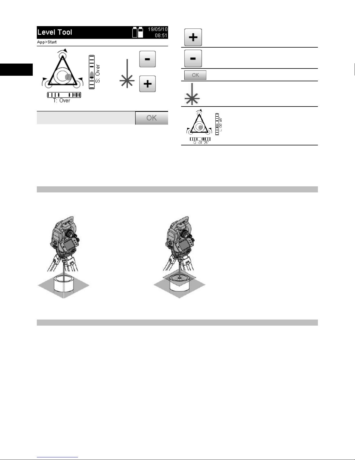
Increase laser plummet intensity
(settings 1–4).
Reduce laser plummet intensity
(settings 1–4).
en
9. Once the electronic “bubble levels” have been centered, check that the laser plummet is aligned exactly with the
mark on the ground and shift the position of the tool laterally on the tripod plate if necessary.
10. Start the tool.
NOTE The OK button becomes active when the level bubbles for line (L) and offset (O) are within a total inclination
of 45".
7.7.3 Setting up over a pipe using the laser plummet
Pipes are often used to mark points on the ground.
In this case, the laser beam is projected into the pipe and the point cannot beseen.
Confirms leveling.
Laser plummet indicator symbol.
The heavier the line, the more
intense the laser plummet lights.
Electronic “bubble level” indicator. Center the bubbles.
Lay a piece of paper, plastic foil or other semi-translucent material on thepipeinordertomakethelaserpointvisible.
7.8 Theodolite application
The theodolite application provides the basic theodolite functions for setting the horizontal circle for taking readings.
24
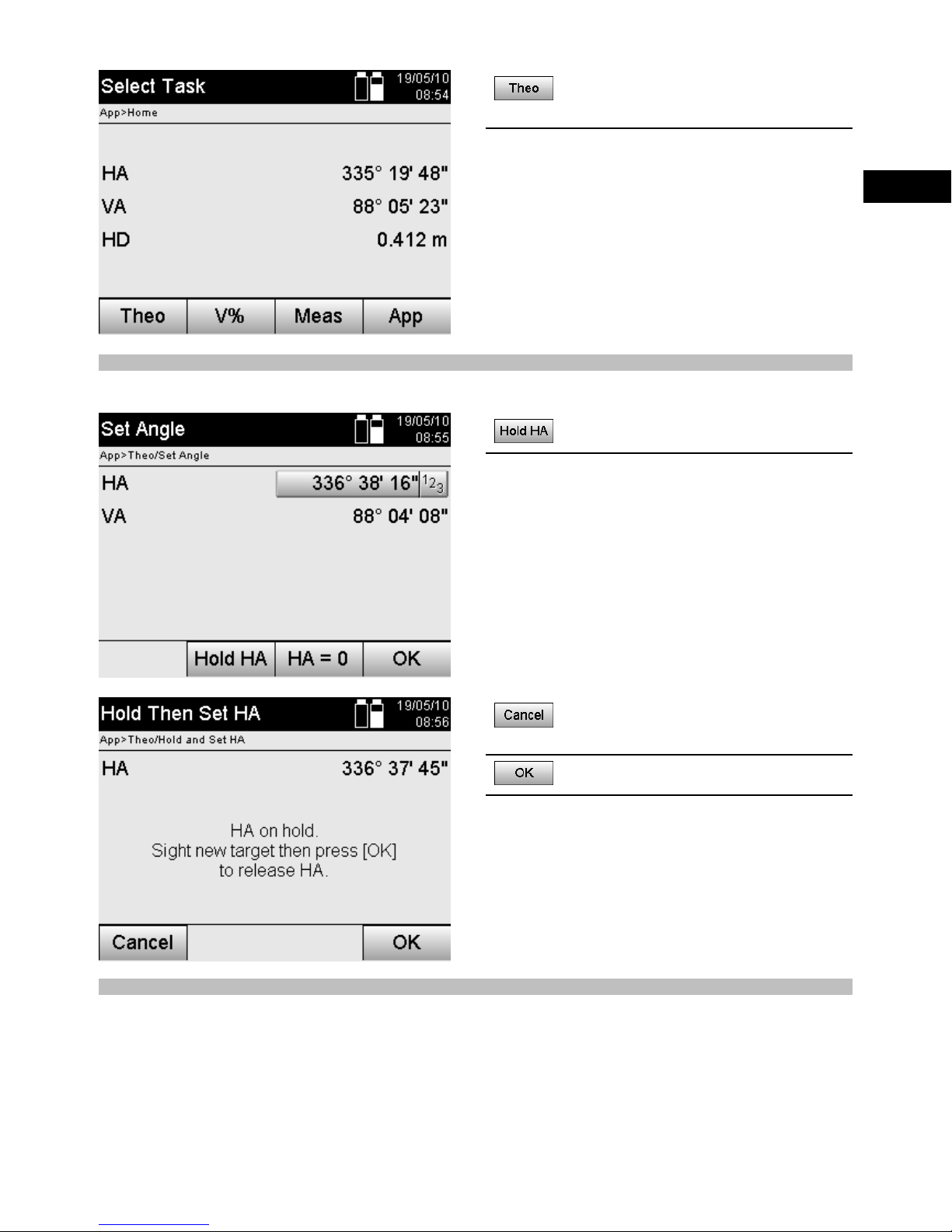
Select the “Theodolite” application for setting horizontal circle
readings.
7.8.1 Setting the horizontal circle display
The horizontal circle reading is held, the tool aimed at the new target and the circle reading then released.
Pause current horizontal circle
reading.
en
7.8.2 Entering a circle reading manually
Any desired circle reading can be entered manually in any position.
Cancel and return to the previous screen without changing the
horizontal value.
Set horizontal value in the display.
25
 Loading...