

Page 1

PM 24
Operating instructions 2 – 38
Mode d'emploi 32-60
*372696*
372696
en
Page 2

1. Product information
Symbols used
The symbols used in these operating instructions have the
following meanings:
WARNING
Usage risk or improper use which can cause severe personal
injury or a fatal accident.
Information which helps the user to employ the tool efficiently
and in a technically correct manner.
Please read these operating instructions carefully before
operating the tool for the first time. Make the instructions
available to all other users so that they can be read before the
tool is operated.
Always keep these operating instructions with the tool.
The operating instructions should always be with the tool
when it is given to other persons.
3
Page 3

4
1. Product information
1. Product information . . . . . . . . . . . . . . . . . . . . . . . . . . . . . . . . . . . . 5
Description of functions . . . . . . . . . . . . . . . . . . . . . . . . . . . . . .6
Operating controls and indicators . . . . . . . . . . . . . . . . . . . . . .7
Technical data . . . . . . . . . . . . . . . . . . . . . . . . . . . . . . . . . . . . .9
Items supplied . . . . . . . . . . . . . . . . . . . . . . . . . . . . . . . . . . . .12
2. Safety information . . . . . . . . . . . . . . . . . . . . . . . . . . . . . . . . . . . . 14
Please read this now! . . . . . . . . . . . . . . . . . . . . . . . . . . . . . . .14
Intended uses . . . . . . . . . . . . . . . . . . . . . . . . . . . . . . . . . . . .14
Warnings and cautions . . . . . . . . . . . . . . . . . . . . . . . . . . . . .15
Laser classification . . . . . . . . . . . . . . . . . . . . . . . . . . . . . . . .17
Electromagnetic compatibility (EMC) . . . . . . . . . . . . . . . . . . .18
Care, storage and transportation . . . . . . . . . . . . . . . . . . . . . .19
Disposal . . . . . . . . . . . . . . . . . . . . . . . . . . . . . . . . . . . . . . . . .21
3. Operation and use . . . . . . . . . . . . . . . . . . . . . . . . . . . . . . . . . . . . 22
Inserting or replacing the batteries . . . . . . . . . . . . . . . . . . . .22
Operating conditions . . . . . . . . . . . . . . . . . . . . . . . . . . . . . . .23
Setting up . . . . . . . . . . . . . . . . . . . . . . . . . . . . . . . . . . . . . . .24
Plumbing with the PM 24 . . . . . . . . . . . . . . . . . . . . . . . . . . . .25
Setting out 90° with the PM 24 . . . . . . . . . . . . . . . . . . . . . . .26
Horizontal levelling and aligning with the PM 24 . . . . . . . . . .27
Using the accessories . . . . . . . . . . . . . . . . . . . . . . . . . . . . . .28
4. Accuracy Check . . . . . . . . . . . . . . . . . . . . . . . . . . . . . . . . . . . . . . 30
5. FCC statement (applicable in US) . . . . . . . . . . . . . . . . . . . . . . . . . 34
6. EC declaration of conformity . . . . . . . . . . . . . . . . . . . . . . . . . . . . . 36
7. Warranty . . . . . . . . . . . . . . . . . . . . . . . . . . . . . . . . . . . . . . . . . . 37
Page 4
5
PM 24PM 24
1. Product information
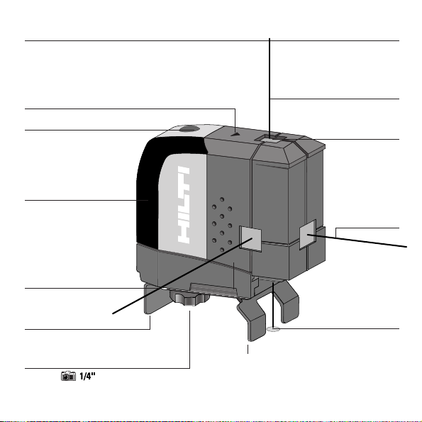
Plumb up beam
(upwards)
ON indicator
1. P roduct information
Tool overview
Laser exit window
Front Beam
90 ° Beam
Battery compartment
(4xtype AA)
Plastic housing
ON/OFF button
Reference beam
(downwards)
Camera tripod
thread
PA 271 Stand
Page 5

6
The Hilti PM 24 is a self-levelling laser tool which allows a single
person to do plumbing, setting out 90° angle, horizontal
levelling and aligning tasks quickly and precisely. It projects four
coincident laser beams (beams with the same point of origin).
All beams have the same operating range of 30 m (100 ft).
However, the maximum recommended distance of the reference
beam (plumb down) is 1 m (3,3 ft), due to its lower accuracy.
Features
– High accuracy of horizontal beams and plumb up beam
(3 mm @ 10 m or 1/8 inch @ 30 ft)
– Additional reference beam downwards
(2 mm @ 1 m or 1/12 inch @ 3 ft)
– Self-levelling within ± 5° in all directions
– Fast self-levelling time: ~ 3 seconds
– Out-of-level warning when the self-levelling range is exceeded
(the laser beams blink)
– Robust, impact-resistant plastic housing
– Small size and light weight - handy to use and transport
– Automatic cut-out: the tool switches off automatically after 15
minutes. Selection of sustained operating mode is also possible.
– Easy to operate
1. Product information
PM 24 Multi Directional Laser – plumbing, setting out 90° angle,
horizontal levelling and aligning
Description of functions, continued
Page 6
7
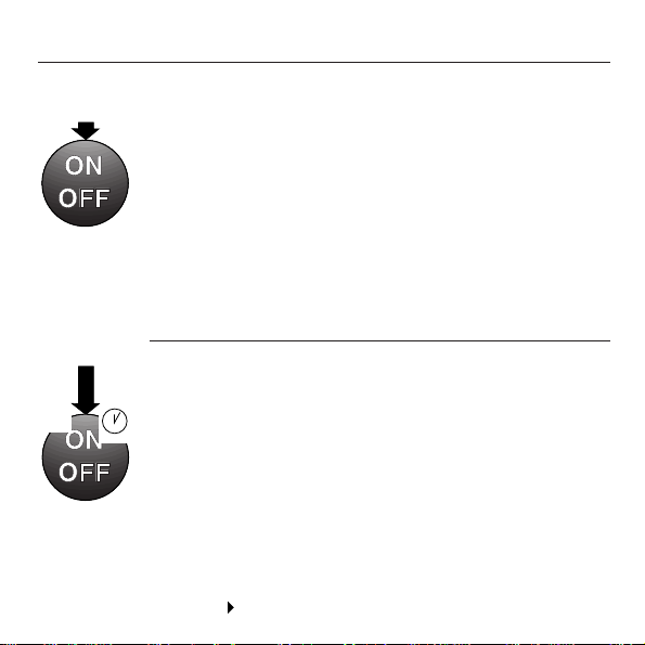
Operating controls and indicators
To switch the tool on/ off:
Press and release the ON/OFF button once.
The tool levels itself automatically within 3 seconds each time
it is moved.
The tool levels itself automatically even when not switched on.
The tool switches off automatically after 15 minutes.
Condition
The tool must be placed on a level surface with a maximum
slope of 5°.
To de-activate the automatic cut-out:
Press and hold the ON/OFF button until the green LED begins
to
blink (approx. 3 seconds) and then release the button.
The tool is then in sustained operating mode, i.e. for long
periods of operation.
Note
Press the ON/OFF button to switch off the tool after use in
order to save battery power.
1. Product information
~3s
Continued
Page 7

8
1. Product information
Operating controls and indicators, continued
Indicator Status
Off – Laser beams off
– Tool is switched off
– Batteries possibly exhausted
Lit continuously – Laser beams on
– Tool in operation
Blinking – Batteries almost exhausted
– The ON/OFF button has been held in
the depressed position in order to
activate sustained operating mode
Control panel
Page 8

9
1. Product information
Technical data
Measurement range
Level, square, plumb up beam: up to 30 m [100 ft]
Recommendation for reference beam
(downwards): 1 m [3 ft]
Accuracy at 25°C [77°F]:
Level beam (horizontality): ± 60’’ (arc seconds) or
± 3 mm @ 10 m [1/8 inch @ 30 ft]
Square beam (horizontality): ± 60’’ (arc seconds) or
± 3 mm @ 10 m [1/8 inch @ 30 ft]
Angle Level/Square beam: 90° ± 60’’
Plumb up beam: 60’’ (arc seconds) or 3 mm @ 10 m
[1/8 inch @ 30 ft]
Reference beam: 7’ (arc minutes) or 2 mm @ 1 m
[1/12 inch @ 3 ft]
Temperature drift:
The drift of all beams is less than 3’’ (arc seconds)/°C.
Beam diameter
< 7 mm @ 10 m / < 14 mm @ 20 m
[< 1/3 inch @ 30 ft / < 3/5 inch @ 60 ft]
Continued
Page 9

10
Levelling Self-levelling within ±5° in all directions
When the tool is out of it’s self-levelling range, the laser
beams blink
Self-levelling time: ~ 3 seconds
Laser Visible Laser, 635 ±10 nm, laser class 2 (IEC 825-1),
Class II (FDA 21 CFR); power output: < 1 mW
Operating mode indicator
Green LED for on/off, battery condition
Automatic cut-out
The tool switches off automatically after 15 minutes.
To de-activate automatic cut-out: Press and hold the ON/ OFF
button (approx. 3 sec.) until the green LED blinks and then
release the button.
Power supply Four alkaline or rechargeable type AA batteries
Battery life at 25°C [77°F]
Alkaline: ≥ 40 h Rechargeable: ≥ 10h
1. Product information
Technical data,continued
Continued
Page 10

11
Operating temperature range
- 10° … + 45°C [+ 14°F … + 113°F]
Storage temperature - 40° … + 63°C [- 40°F … + 145°F], dry
Protection class
IP 52(IEC 529) protection against dust and dripping water
(excluding battery compartment)
Weight 0.5 kg (1.1 lbs), including 4 batteries
Dimensions 109 (L) x 51 (W) x 96 (H) mm
4.3 (L) x 2 (W) x 3.8 (H) inches
1. Product information
Technical data,continued
Page 11
12
PM 24
+20
+10
-10
-20mm
-20mm
-10
+10
+20
PA 211
mm
inch
+10
-10
PA 221
PM 24
PA 240
PA 240
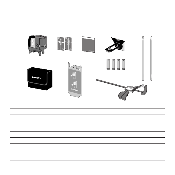
1. Product information
Items supplied - PM 24 Contractor Kit
Packed in a Hilti transport Case
Pos. Pieces Designation
1 1 PM 24 multi directional laser with metal stand PA 271
2 2 PA 211 or PA 221 Target plate
3 1 Operator’s manual
4 1 PA 240 Magnetic bracket
5 1 Soft pouch
6 1 PA 230 Wall bracket
7 4 Batteries
8 1 PA 250 Frame clamp
9 2 Marking pens
1
2
3
4
5
6
9
7
8
0
2
+
+
2
0
0
1
+
+
1
1
0
+
/
2
+
1
0
m
m
i
n
c
h
0
1
-
1
0
1
0
1
/
m
2
m
0
2
-
2
0
PM 24
m
m
P
P
A
A
2
2
2
1
1
1
P
M
2
4
P
A
2
4
0
+
-+-+-+-
P
A
2
3
0
Page 12
13
1. Product information
+20
+10
-10
-20mm
-20mm
-10
+10
+20
PA 211
mm
inch
+10
-10
PA 221
PM 24
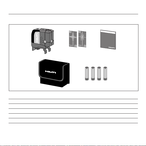
Items supplied - PM 24 Single unit
Pos. Pieces Designation
1 1 PM 24 multi directional laser with metal stand PA 271
2 2 PA 211 or PA 221 Target plate
3 1 Operator’s manual
4 1 Soft pouch
5 4 Batteries
12
3
45
PM 24
P
M
2
0
2
+
+
2
0
0
1
+
+
1
1
0
+
/
2
+
1
0
m
m
i
n
c
h
0
1
-
-
1
0
-
1
0
1
-
/
m
2
m
0
2
-
-
2
0
m
m
P
P
A
A
2
2
1
2
1
1
4
+
-+-+-+-
Page 13

14
Intended uses
2. Safety information
2. Safety information
This information is intended to enable owners and users of the
Hilti PM 24 to identify any operating risks in good time, i.e. to
eliminate any such risks in advance where possible.
The owner of the tool must ensure that these instructions are
understood and followed by all users.
Please read this now!
The Hilti PM 24 is designed to be used indoors for determining
and checking heights or deviations in heigth
at points in the horizontal plane, vertical lines, alignment lines,
the position of partition walls (vertical and at right angles to a
reference line) and for marking plumb points.
For example:
– Transferring datum marks and height marks
– Marking out the position of partitions (at right angles and in
the vertical plane)
– Aligning equipment/installations and other structural
elements in three axes
– Checking and transferring right angles
– Transferring points marked on the floor to the ceiling
Page 14

15
2. Safety information
WARNING
- Dot not use the product without prior instruction
- Dot not use the product outside its operating limits
- Do not make any conversions or modifications to the product
- Do not render safety devices ineffective or removing notices
and warning signs
- Dot not have inadequate safety measures at the location
where the product is in use (e.g. levelling or alignment work at
a roadside etc.)
- Keep the tool out of reach of children. Laser tools do not
belong in children’s hands.
- Avoid unusual body positions when carrying out alignment
work from ladders. Make sure that your stance is secure and
always stay in balance.
- The battery must be removed from the tool when it is shipped.
- The tools are not designed for use in environments where
there is a risk of explosion.
CAUTION
- Check the tool for possible damage before use. If the tool is
damaged, have it repaired at a Hilti repair centre.
Warnings and cautions
Page 15

16
2. Safety information
- If the tool has been dropped or subjected to other
mechanical forces, its accuracy should be checked. For
safety’s sake, check its accuracy before each use.
- When using adaptors, always ensure that the tool is screwed
on securely.
- When the tool is brought into a warmer environment from a
very low temperature, or vice versa, it should be allowed to
become acclimatised to the ambient temperature before it is
operated.
- Measurements taken through panes of glass or other
objects may be inaccurate.
- To avoid inaccurate measurements, always keep the laser
beam exit windows clean.
- Although the tool is designed for use under arduous
conditions on construction sites, like any other item of
optical equipment (e.g. binoculars, spectacles), it should be
handled with care.
- Although the tool is designed to prevent the entry of moisture, it
should be wiped dry before being put away in its carrying case.
- The tool is not designed for use in rain.
- Do not use damaged batteries.
- The unit may not be opened by unauthorized persons.
Warnings and cautions, continued
Page 16

17
Laser warnings for the USA based on FDA 21 CFR:
2. Safety information
The PM 24 plumb laser corresponds to laser class 2, based on the
standards IEC 825-1 / EN 60825, and class II based on FDA 21 CFR.
The eyelid closure reflex protects the eyes should anyone happen to
look briefly into the laser beam. However, this eyelid closure reflex
can be impaired by medicines, alcohol or drugs. These devices may
be used without further protective measures. Nevertheless, as with
the sun, care should be taken to avoid looking directly into the
light source. Do not direct the laser beam at people.
Laser classification
Laser warnings based on IEC 825 / EN 60825:
Laser
Do not stare into beam
Laser Class 2
PM 24
Page 17

18
2. Safety information
Electromagnetic compatibility refers to the ability of the Hilti
PM 24 to function correctly in an environment where it is
exposed to electromagnetic radiation and electrostatic discharge,
without causing electromagnetic interference to other devices.
WARNING
There may be a possibility of interference to other equipment
due to electromagnetic radiation.
Although the Hilti PM 24 complies with the strict requirements
of the relevant directives and standards, Hilti cannot entirely
rule out the possibility of interference with other equipment.
CAUTION
Measurements may exceed tolerances where interference is
caused by powerful electromagnetic radiation.
Although the Hilti PM 24 complies with the strict requirements
of the relevant directives and standards, Hilti can not entirely
rule out the possibility of the PM 24 being subject to
interference caused by very intense electromagnetic radiation,
e.g. in the immediate vicinity of radio transmitters, radio
communication equipment, diesel generators etc.
Check the readings for plausibility when the tool is used under
these conditions.
Electromagnetic compatibility (EMC)
Page 18

19
2. Safety information
Cleaning and drying
- Blow dust off the lenses.
- Don’t touch the glass with your fingers.
- Use only clean, soft cloths for cleaning. If necessary,
moisten the cloth slightly with pure alcohol or a little water.
Do not use any other liquids as these may damage the plastic
components.
Observe the temperature limits when storing your equipment. This
is particularly important in winter or summer if the equipment is
kept inside a motor vehicle (-30°C to +60°C / -22°F to +140°F).
Storage
- Remove the tool from its case if it has become wet. The tool,
its carrying case, and accessories should be cleaned and
dried (max 40°C / 108°F). Put the equipment back into its
case only when it is completely dry.
- Check the accuracy of the equipment by taking test
measurements before it is used after a long period of
storage or transportation.
Transportation
Your equipment should be shipped in the Hilti shipping carton
or packaging of similar quality.
Always remove the batteries before shipping.
Care, storage and transportion
Page 19

20
2. Safety information
Disposal
WARNING
Improper disposal of the equipment may lead to the following:
- Burning of plastic components generates toxic fumes which
may present a health hazard.
- If damaged or exposed to very high temperatures, batteries
may explode, causing poisoning, burns, acid burns or
environmental pollution.
- Careless disposal enables unauthorised persons to make
improper use of the equipment. This may lead to serious
injury to themselves or to a third party and to pollution of
the environment.
- Dispose batteries according to national requirements.
Most of the materials from which Hilti tools are manufactured
can be recycled.
The materials must be correctly separated before they can be
recycled.
In many countries, Hilti has already made arrangements for
taking back old tools for recycling.
Please ask your Hilti customer service department or Hilti
representative for further information. Please help to protect
and maintain our environment.
Page 20

21
2. Safety information
Disposal
Part, assembly Main material Recycling
Casing Plastic Plastic recycling
On-off switch Plastic Plastic recycling
Electronics Various Electronics scrap
Screws, small parts Steel Scrap metal
Soft pouch Woven synthetic fiber Plastic recycling
Frame clamp Metal, steel Metal
PA 271 stand Aluminium, metal Metal, plastic
Wall mount Metal, steel Metal
Magnetic bracket Steel Metal
PA 211/221 target plate Plastic Plastic recycling
Page 21

22
3. Operation and use
3. Operation and use
Inserting or replacing the batteries
Green indicator blinks – the laser beams blink for a few
minutes and then switches off automatically ➞ battery voltage
too low ➞ insert new batteries:
Always replace the complete set of batteries!
– Do not mix old and new batteries.
– Do not mix batteries of different makes or use batteries of
different types.
open
close
Page 22

23
3. Operation and use
Operating conditions
1 Observe the operating temperature range.
2 Place the tool on a level, steady surface (the floor).
Accuracy of the tool can only be ensured when the operating
conditions (points 1 and 2) are observed.
PM 24
PM 24
PM 24
PM 24
Page 23

24
3. Operation and use
Setting up
Marking the reference point – the possibilities
1 Mark the laser reference beam point by hand.
Set up the laser plumbline with the spot on the mark.
2 For other applications, e.g. alignment with the edge of a dry
wall track or board, etc., position the PM 24 against the track.
The laser reference beam spot is positioned exactly on the
edge of the track and at the center of the tool.
PM 24
PM 24
1
2
Page 24

25
PM 24PM 24
Plumbing with the PM 24
3. Operation and use
Procedure
1 Position the tool on the marked reference point.
2 Switch on the tool.
The ON indicator lights (green), the laser beam lights up and
the tool levels itself automatically.
3 The reference beam spot must coincide with the mark.
Correct the position of the tool if necessary.
4 Mark the plumb up beam spot or use the PA 211 target
plate, for example, to check for plumb along a wall.
Note: The other beams have been omitted from illustration for clarity.
PM 24 PM 24
Page 25

26
Setting out 90° angle with the PM 24
Procedure:
1. Place PM 24 against the reference wall.
2. Using the target plate, adjust the front beam so that it is
parallel to the wall.
3. Now with the right, 90° beam and the target plate mark off
your points.
3. Operation and use
+1/
2
+10
mm inch
-10
-1/
2
PA 221
y
x
x
1
2
x
x
3
4
Page 26

27
Horizontal Levelling and aligning with the PM 24
The PM 24 can do horizontal levelling and aligning in two ways:
1. Directly over the surface ➪ Place the PM 24 over the reference
surface. Level the other surface using the target plate.
2. Mounted with an accessory ➪ Mount the PM 24 with an
appropriate accessory at the desired height. Rotate the
PM 24 and mark the points or perform the installation directly.
When performing levelling and aligning applications with the
PM 24 mounted on the PA 271 stand, first check the
reference by holding the target plate directly in front of the
tool. This reference may or may not be on the center of the
target plate and will apply to all further levelling points.
3. Operation and use
Page 27

28
3. Operation and use
Using the accessories
a) Frame clamp
When using the Frame clamp (e.g. at a door frame), the magnetic bracket can
be slid onto the stationary jaw of the clamp by way of the rail at the rear. The
protective cover should be fitted over the magnet.
b) Magnetic bracket
The protective cover should be removed from the magnets before using the
magnetic bracket.
Page 28

29
c) Wall bracket
The wall bracket is used for mounting the PM 24 on a non-magnetic surface.
Screws or nails can be used to fasten the wall bracket to surfaces of this kind.
The PM 24 can be set up on the wall bracket with the magnetic holder
(protective cover removed).
d) Tripod Head
Tripod Head with 1/4 “ thread.
3. Operation and use
Page 29

30
The tool should be checked on regular intervals at room temperatures
(25˚C or 77˚F) to ensure compliance with the technical specifications.
Plumb Up Beam
1. Mark a point (a cross) on the floor of a high room (e.g. a
stairwell, (5-10m or 15-30 ft)).
2. Put the tool on a level floor and switch it on.
3. Bring the reference beam point on top of the center of the cross.
4. Mark the corresponding up beam on the ceiling (easier if paper is
taped there)
5. Turn the tool 90° so that the reference beam stays on the same
point and mark again on the ceiling.
6. Repeat the same at 180° and at 270°.
7. The 4 resulting points on the ceiling define a circle of which the
crossing point of the diagonals d
1
(1– 3) and d2(2– 4) mark the
exact plumb point.
8. Calculate accuracy:
The result of the formula refers to the accurcy in “mm @ 10 m” (equation
(1)) or the accuracy in “inch @ 30 ft (equation (2)). The result shall be
within the PM 24 specification: 3 mm @ 10 m [1/8 inch @ 30 ft].
4. Accuracy check
4. Accuracy check
Result =
10
Room height [m]
.
(d1+ d2) [mm]
4
(1) or
Result =
30
Room height [ft]
.
(d1+ d2) [inch]
4
(2)
Page 30

31
Page 31

32
Level and Square Beam (horizontality)
1. Place the PM 24 on the floor near wall (A). Mark the center
of the laser spot (1) with a cross. Turn the tool through
180 °. Mark the center of the laser spot (2) with a cross.
2. Place the tool near wall (B) and direct the beam towards
wall (B). Mark the center of the laser spot (3) with a cross.
Pivot the tool trough 180 °. Mark the center of the laser
spot (4) with a cross.
3. Measure the distance d1 and d2. Mark the middle point in
d1 and d2. If the reference points 1 and 3 are on different
sides of the middle point (see the example), subtract d2
from d1. If they are on the same side of the middle point,
add d1 to d2. Divide the result by twice the length of the
room.
For PM 24: max. error = 3mm / 10m or 1/4” at 60feet.
Example: d1 = 6mm, d2 = 4mm, room length = 10m,
points 1 and 3 are on different sides of the real level line.
6mm-4mm =2mm
=
1mm / 10m
10m X 2 20 m
Level / Square Beam Angle
An effective test of the accuracy of the angle between level and
square beams can only be carried out in a Hilti Repair Center.
Page 32

33
1
Room must have 10 to 20 m (60 to 100 ft)
AB
1
180
2
2
AB
180
4
3
3
AB
1
d
1
4
D
2
d
2
3
Page 33

34
5. FCC statement (applicable in U.S.)
WARNING
This equipment has been tested and found to comply with the
limits for a class B digital device, pursuant to part 15 of the
FCC rules.
This device complies with part 15 of the FCC Rules. Operation
is subject to the following two conditions:
(1) This device may not cause harmful interference, and (2)
this device must accept any interference received, including
interference that may cause undesired operation. However,
there is no guarantee that interference will not occur in a
particular installation. If this equipment does cause harmful
interference to radio or television reception, which can be
determined by turning the equipment off and on, the user is
encouraged to try to correct the interference by one or more of
the following measures:
– Reorient or relocate the receiving antenna.
– Increase the separation between the equipment and receiver.
– Connect the equipment into an outlet on a circuit different
from that to which the receiver is connected.
5. FCC statement (applicable in U.S.)
Continued
Page 34

35
5. FCC statement (applicable in U.S.)
5. FCC statement (applicable in U.S.), continued
PM 24
– Consult the dealer or an experienced radio/TV technician for
help.
WARNING
Changes or modifications not expressly approved by Hilti for
compliance could void the user’s authority to operate the
equipment.
Label
PM 24
Page 35

36
6. EC declaration of conformity
6. EC declaration of conformity
Designation: PM24
Serial no.: 500000 –800000
Year of design: 2001
-conform
We declare, on our sole responsibility, that this product
complies with the following standards or standardisation
documents: 89/336/EWG
Hilti Corporation
Armin Spiegel
Head of Business Unit
Positioning Systems
12/2001
Bodo Baur
Quality Manager of Business
Unit
Positioning Systems
12/2001
Page 36

37
7. Warranty
7. Warranty
Hilti warrants that the tool supplied is free of defects in
material and workmanship. This warranty is valid so long as
the tool is operated and handled correctly, cleaned and
serviced properly and in accordance with the Hilti Operating
Instructions, all warranty claims are made within 12 months
from the date of the sale (invoice date), and the technical
system is maintained. This means that only original Hilti
consumables, components and spare parts may be used in the
tool. (Unless stringent national rules stipulate a longer
minimum warranty period.)
This warranty provides the free-of-charge repair or
replacement of defective parts only. Parts requiring repair or
replacement as a result of normal wear and tear are not
covered by this warranty.
Additional claims are excluded, unless stringent national
rules prohibit such exclusion. In particular, Hilti is not
obligated for direct, indirect, incidental or consequential
damages, losses or expenses in connection with, or by
Continued
Page 37

38
7. Warranty, Addresses
7. Warranty,continued
reason of, the use of, or inability to use the tool for any
purpose. Implied warranties of merchantability or fitness for
a particular purpose are specifically excluded.
For repair or replacement, send tool and / or related parts
immediately upon discovery of the defect to the address of the
local Hilti marketing organization provided.
This constitutes Hilit’s entire obligation with regard to warranty
and supersedes all prior or contemporaneous comments and
oral or written agreements concerning warranties.
Hilti Corporation
FL-9494 Schaan, Principality of Liechtenstein
Internet: www.hilti.com
 Loading...